Embed Size (px)
Citation preview
7/16/2019 InTech-Metasurfaces for High Directivity Antenna Applications
http://slidepdf.com/reader/full/intech-metasurfaces-for-high-directivity-antenna-applications 1/25
20
Metasurfaces for High DirectivityAntenna Applications
Shah Nawaz Burokur, Abdelwaheb Ourir,André de Lustrac and Riad Yahiaoui
Institut d’Electronique Fondamentale,Univ. Paris-Sud, CNRS UMR 8622,
France
1. Introduction
There has been a lot of study published in literature on the improvement of the
performances of microstrip patch antennas. Most of the solutions proposed in the past were
to use an array of several antennas. The particular disadvantage of this method comes from
the feeding of each antenna and also from the coupling between each element. Other
interesting solutions have then been suggested: the first one (Jackson & Alexópoulos, 1985)
was to make use of a superstrate of either high permittivity or permeability above the patch
antenna and the second one proposed (Nakano et al., 2004), is to sandwich the antenna by
dielectric layers of the same permittivity. A Left-Handed Medium (LHM) superstrate where
both permittivity and permeability are simultaneously negative has also been suggested(Burokur et al., 2005). The numerical study of a patch antenna where a Left-Handed
Medium (LHM) is placed above has been done and in this case a gain enhancement of about
3 dB has been observed. However, these solutions are all based on non-planar designs
which are bulky for novel telecommunication systems requiring compact low-profile and
environment friendly directive antennas.
To overcome the major problem of complex feeding systems in antenna arrays, the design of
compact directive electromagnetic sources based on a single feeding point has become an
important and interesting research field. Different interesting solutions based on this
concept have been proposed. At first, resonant cavities in one-dimensional (1-D) dielectric
photonic crystals have been used (Cheype et al., 2002). Afterwards, three dimensional (3-D)structures have been used, leading to better performances (Temelkuran et al., 2000). Another
interesting solution proposed by Enoch et al. was to use the refractive properties of a low
optical index material interface in order to achieve a directive emission (Enoch et al., 2002).
The authors have shown how a simple stack of metallic grids can lead to ultra-refraction.
Because the resulting metamaterial structure has an index of refraction, n, which is positive,
but near zero, all of the rays emanating from a point source within such a slab of zero index
material would refract, by Snell’s Law, almost parallel to the normal of every radiating
aperture. We shall note that these solutions are all also based on the use of a bulky 3-D
material.
www.intechopen.com
7/16/2019 InTech-Metasurfaces for High Directivity Antenna Applications
http://slidepdf.com/reader/full/intech-metasurfaces-for-high-directivity-antenna-applications 2/25
Metamaterial534
Otherwise, the most common method to reach directive emission is obviously based on theFabry-Pérot reflex-cavity mechanism (Trentini, 1956). Such cavities have first been
considered quite bulky too since a thickness of half of the working wavelength is required
(Akalin et al., 2002). But recently, the introduction of composite metasurfaces has shown that
the half wavelength thickness restriction in a Fabry-Pérot cavity can be judiciously avoided.For example, Feresidis et al. showed that a quarter wavelength thick Fabry-Pérot cavity can
be designed by using Artificial Magnetic Conductor (AMC) surfaces introducing a zero
degree reflection phase shift to incident waves (Feresidis et al., 2005). Assuming no losses
and exactly 0° reflection phase, the surface is referred to as a Perfect Magnetic Conductor
(PMC), which is the complementary of a Perfect Electric Conductor (PEC). The latter AMC
surfaces have been first proposed in order to act as the so called High Impedance Surface
(HIS) (Sievenpiper et al., 1999). This HIS is composed of metallic patches periodically
organized on a dielectric substrate and shorted to the metallic ground plane with vias,
appearing as “mushroom” structures. In a particular frequency band where reflection phase
is comprised between -90° and +90°, this surface creates image currents and reflections in-phase with the emitting source instead of out of phase reflections as the case of conventional
metallic ground plane. The HIS allows also the suppression of surface waves which travel
on conventional ground plane. However, the HIS of Sievenpiper needs a non-planar
fabrication process, which is not suitable for implementation in lots of microwave and
millimetric circuits.
The reflex-cavity antenna proposed by Feresidis was composed of two planar AMC surfaces
and a microstrip patch antenna acting as the primary (feeding) source. The first AMC
surface was used as the feeding source’s ground plane so as to replace the PEC surface and
hence, to achieve a 0° reflection phase. The second one acted as a Partially Reflective Surface
(PRS) with a reflection phase equal to 180°. This idea has then been pushed further by Zhouet al. (Zhou et al., 2005). By taking advantage of the dispersive characteristics of
metamaterials, the authors designed a subwavelength cavity with a thickness smaller than a
10th of the wavelength. Compared to Feresidis, Zhou made use of a non-planar mushroom
structure with a dipole acting as the feeding source.
In this chapter, using a novel composite metamaterial, made of both capacitive and
inductive grids, we review our recent works in the fields of low-profile and high-gain
metamaterial-based reflex-cavity type antennas. First, we will show how our group has
lately further reduced the cavity thickness by λ /30 for applications to ultra-thin directive
antennas by using a PEC surface as the source’s ground plane and one subwavelength
metamaterial-based composite surface as the PRS. We will also present how anoptimization of the cavity has also been undertaken in order to reduce the thickness to
λ /60 by using an AMC surface instead of the PEC ground plane and a metasurface as
PRS. We will then present the modeling and characterization of resonant cavities for
enhancing the directivity. Finally, a phase controlled metasurface will be proposed for
applications to beam steerable and frequency reconfigurable cavity antennas. Numerical
analyses using Finite Element Method (FEM) based software HFSS and CST’s
Transmission Line Modeling (TLM) solver MICROSTRIPES together with discussions on
the fabrication process and the experimental results will be presented for the different
cavities mentioned above.
www.intechopen.com
7/16/2019 InTech-Metasurfaces for High Directivity Antenna Applications
http://slidepdf.com/reader/full/intech-metasurfaces-for-high-directivity-antenna-applications 3/25
Metasurfaces for High Directivity Antenna Applications 535
2. Operating principle of the Fabry-Pérot reflex-cavity
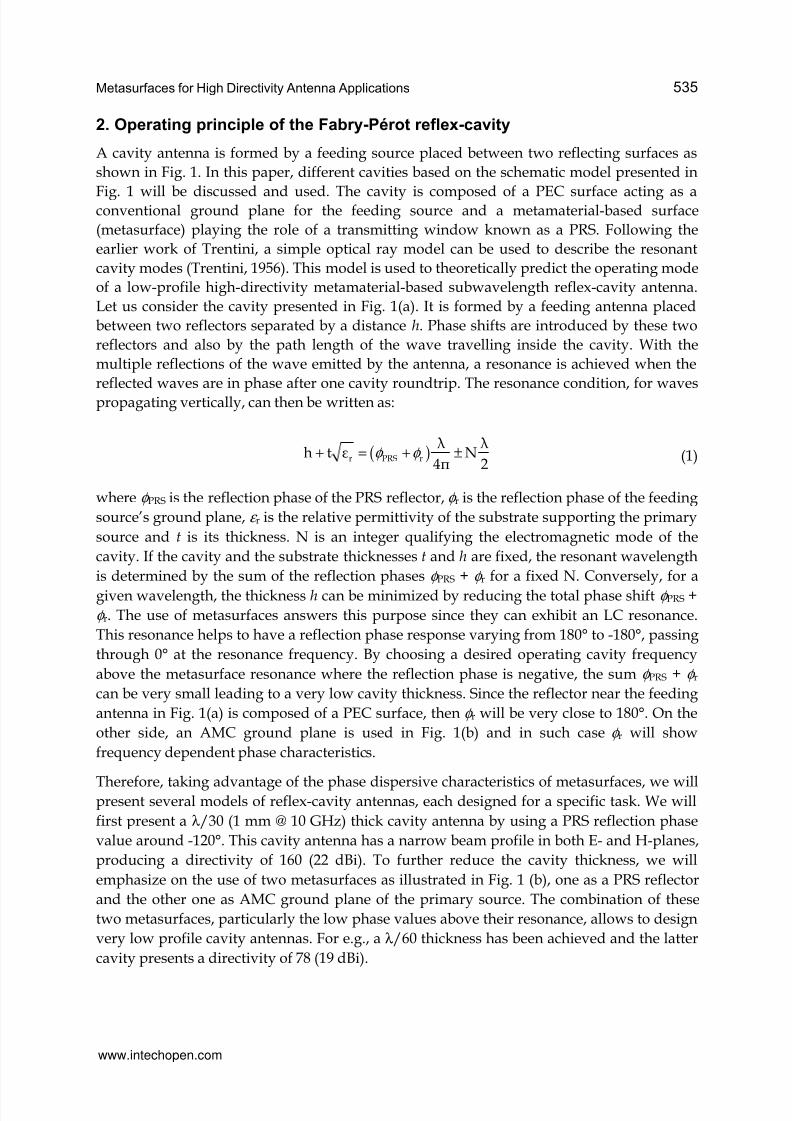
A cavity antenna is formed by a feeding source placed between two reflecting surfaces as
shown in Fig. 1. In this paper, different cavities based on the schematic model presented in
Fig. 1 will be discussed and used. The cavity is composed of a PEC surface acting as aconventional ground plane for the feeding source and a metamaterial-based surface
(metasurface) playing the role of a transmitting window known as a PRS. Following the
earlier work of Trentini, a simple optical ray model can be used to describe the resonant
cavity modes (Trentini, 1956). This model is used to theoretically predict the operating mode
of a low-profile high-directivity metamaterial-based subwavelength reflex-cavity antenna.
Let us consider the cavity presented in Fig. 1(a). It is formed by a feeding antenna placed
between two reflectors separated by a distance h. Phase shifts are introduced by these two
reflectors and also by the path length of the wave travelling inside the cavity. With the
multiple reflections of the wave emitted by the antenna, a resonance is achieved when the
reflected waves are in phase after one cavity roundtrip. The resonance condition, for waves
propagating vertically, can then be written as:
( )r PRS r
λ λh t N
4π 2φ φ + = + ± (1)
where φ PRS is the reflection phase of the PRS reflector, φ r is the reflection phase of the feeding
source’s ground plane, ε r is the relative permittivity of the substrate supporting the primary
source and t is its thickness. N is an integer qualifying the electromagnetic mode of the
cavity. If the cavity and the substrate thicknesses t and h are fixed, the resonant wavelength
is determined by the sum of the reflection phases φ PRS + φ r for a fixed N. Conversely, for a
given wavelength, the thickness h can be minimized by reducing the total phase shift φ PRS +
φ r. The use of metasurfaces answers this purpose since they can exhibit an LC resonance.
This resonance helps to have a reflection phase response varying from 180° to -180°, passing
through 0° at the resonance frequency. By choosing a desired operating cavity frequency
above the metasurface resonance where the reflection phase is negative, the sum φ PRS + φ r
can be very small leading to a very low cavity thickness. Since the reflector near the feeding
antenna in Fig. 1(a) is composed of a PEC surface, then φ r will be very close to 180°. On the
other side, an AMC ground plane is used in Fig. 1(b) and in such case φ r will show
frequency dependent phase characteristics.
Therefore, taking advantage of the phase dispersive characteristics of metasurfaces, we willpresent several models of reflex-cavity antennas, each designed for a specific task. We will
first present a λ /30 (1 mm @ 10 GHz) thick cavity antenna by using a PRS reflection phase
value around -120°. This cavity antenna has a narrow beam profile in both E- and H-planes,
producing a directivity of 160 (22 dBi). To further reduce the cavity thickness, we will
emphasize on the use of two metasurfaces as illustrated in Fig. 1 (b), one as a PRS reflector
and the other one as AMC ground plane of the primary source. The combination of these
two metasurfaces, particularly the low phase values above their resonance, allows to design
very low profile cavity antennas. For e.g., a λ /60 thickness has been achieved and the latter
cavity presents a directivity of 78 (19 dBi).
www.intechopen.com
7/16/2019 InTech-Metasurfaces for High Directivity Antenna Applications
http://slidepdf.com/reader/full/intech-metasurfaces-for-high-directivity-antenna-applications 4/25
Metamaterial536
(a)
(b)
Fig. 1. Resonant cavity formed by a PEC ground plane and a metamaterial-based PRS (a)and, an AMC ground plane and a metamaterial-based PRS (b).
Since directivity depends strongly on the radiating aperture which is defined by the fielddistribution illuminating the PRS, we will present two ways on how we can manipulate thedirectivity of such reflex-cavity antennas. First, we will present the use of lateral PEC wallsin the cavity antenna to form what we will refer to as metallic cavity. This method allows toenhance the directivity by 3 dB compared to the case where the cavity is open on the lateralsides. Also, the metallic cavity presents lower backward radiations due to the confinementof electromagnetic radiation, therefore increasing the front-to-back (FBR) ratio. Secondly, inorder to optimize the field distribution illuminating the PRS, we will study the use ofseveral primary sources inside the cavity. We will show how judiciously placing thedifferent sources in the cavity helps to increase the directivity to more than 6 dB compared
to single source fed cavity.
Finally, we will present beam steerable and frequency reconfigurable cavity antennas. Forthe beam steering, we will in a first step study a cavity where the PRS presents a locallyvariable phase. The latter PRS then acts as a phased array of micro-antennas, thus allowingto achieve beam steering. This concept has been pushed further by designing anelectronically tunable metasurface via the incorporation of lumped elements (varactordiodes). This active metasurface can be used as PRS for two different tasks. Firstly, by
applying different bias voltage along the PRS, a locally variable phase is obtained and isfully compatible for beam steering. On the other side, if we change the bias voltage of all thelumped elements similarly, then we can tune the operation frequency of the PRS so as toachieve a frequency reconfigurable reflex-cavity antenna.
www.intechopen.com
7/16/2019 InTech-Metasurfaces for High Directivity Antenna Applications
http://slidepdf.com/reader/full/intech-metasurfaces-for-high-directivity-antenna-applications 5/25
Metasurfaces for High Directivity Antenna Applications 537
3. Analysis of the planar metasurfaces
The cavity presented in Fig. 1 requires the application of a metamaterial-based surface. So in
this section, we will design planar metamaterial-based surfaces for operation near 10 GHz.
(a)(b)
(c) (d)
(e) (f)
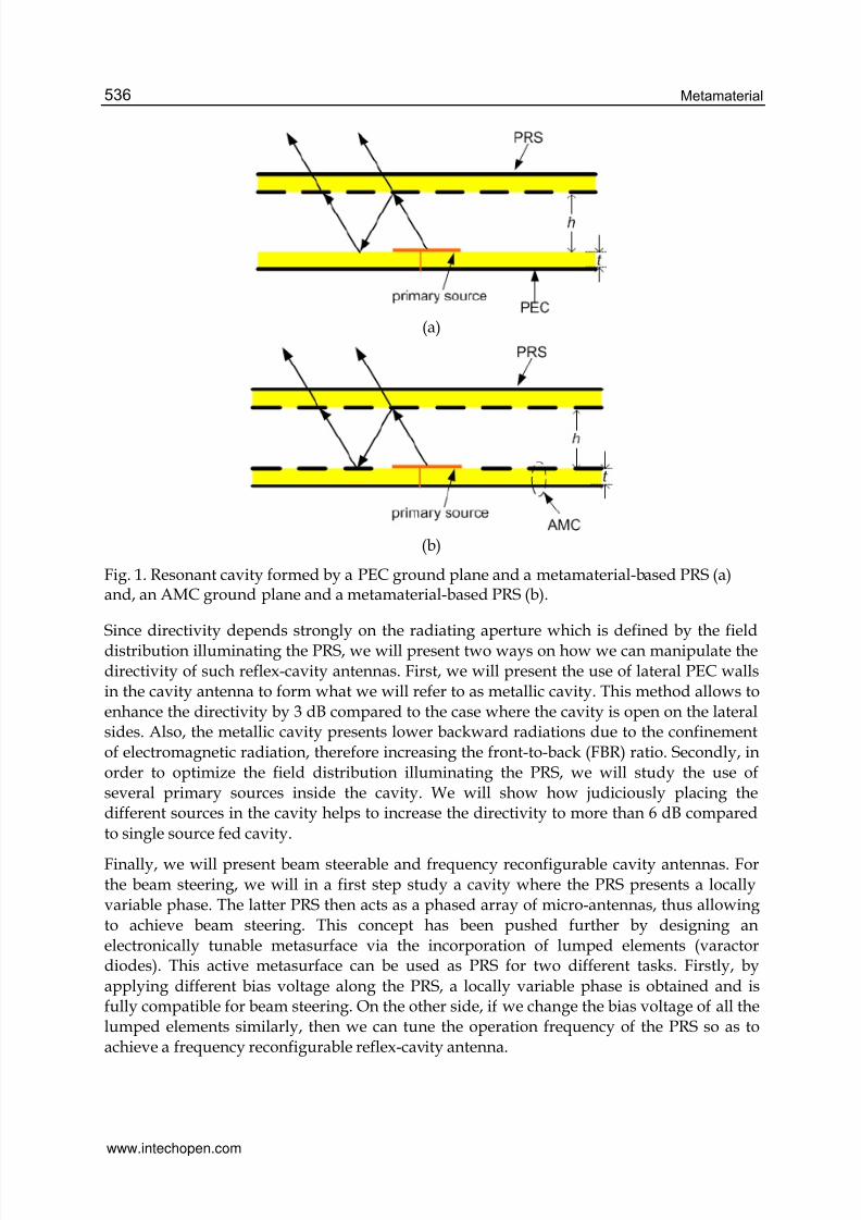
Fig. 2. Unit cell of AMC ground plane (a) and metamaterial-based PRS (b). Calculated
reflection magnitude and phase of the AMC ground plane (c), (e) and reflection and
transmission magnitudes and phases of the metamaterial-based PRS (d), (f).
www.intechopen.com
7/16/2019 InTech-Metasurfaces for High Directivity Antenna Applications
http://slidepdf.com/reader/full/intech-metasurfaces-for-high-directivity-antenna-applications 6/25
Metamaterial538
The surface used by our group in order to achieve the AMC ground plane is made of ametamaterial composed of 2-D periodically subwavelength metallic square patchesorganized on one face of a dielectric substrate as illustrated in Fig. 2(a). The differentdimensions of the patches are as follows: period p1 = 4 mm and width w1 = 3.8 mm. Another
surface which we are going to use for the PRS of the cavity is made of a compositemetamaterial consisting of simultaneously a capacitive and an inductive grid on the twofaces of a dielectric substrate. The capacitive grid is also formed by 2-D periodic metallicpatches (period p2 = 4 mm and width w2 = 3.6 mm) whereas the inductive grid is formed bya 2-D periodic mesh (line width l2 = 1.2 mm) as shown in Fig. 2(b). Concerning the substrate,
we have used the double copper cladded epoxy substrate of relative permittivity ε r = 3.9, of
tangential loss tanδ = 0.0197 and having a thickness of 1.2 mm. The size of the differentpatterns has been chosen in order to minimize the phase of the reflection coefficient near 10GHz while providing a sufficiently high reflectance (~90%).
The metasurfaces are analyzed numerically using the finite element software HFSS so as to
present its characteristics in terms of reflection and transmission. Simulations are performedon a unit cell together with appropriate periodic boundary conditions. The results are
presented in Fig. 2(c) and Fig. 2(d). As shown, the calculated resonance frequency of the
AMC surface and PRS reflector is respectively 10.4 GHz and 9.7 GHz. At resonance, phase
crosses 0° as illustrated in Fig. 2(e) and Fig. 2(f).
The composite metamaterial acts as a resonant filter which presents a reflection phase
varying from 180° to –180°, depending on the frequency. This variation helps to be more
flexible in designing thin cavities by choosing reflection phase values below 0°.
4. Metamaterial-based low-profile highly directive cavity antennaIn this section, we discuss about the design, implementation and characterization of low
profile and highly directive cavity antennas. Two different models are presented; an AMC-
PRS cavity and a PEC-PRS cavity.
4.1 AMC-PRS cavity antenna
The AMC-PRS cavity antenna is formed by the AMC reflector and the metasurface reflectorused as PRS together with a patch antenna designed to operate near 10 GHz (Ourir et al.,
2006a). The patch antenna of dimensions 6.8 × 7 mm2 is placed on the AMC in the cavity as
shown in Fig. 1(b). The reflectors used are those presented in Fig. 2. The different phases
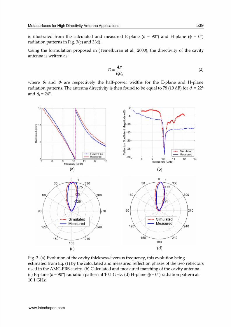
(simulated and measured) are used to estimate the thickness h of the AMC-PRS cavity asgiven by Eq. (1). Fig. 3(a) shows that h first decreases with increasing frequency of the first
resonant mode (N = 0) to the point where a cavity zero thickness is reached at around 10.2
GHz. Then a jump in the mode occurs leading to an abrupt variation of h and the valuedecreases again for N = 1. A cavity thickness h = 0.5 mm is chosen for the cavity. The
thickness h of the Fabry-Perot cavity formed by the two reflectors is adjusted mechanically.
The lateral dimensions of the reflector plates are 17 × 17 cm2. This thickness leads to a good
matching of the cavity at 10.1 GHz (Fig. 3(b)) corresponding to the design of a λ /60 cavity.This frequency is in good agreement with the resonance frequency calculated from the
optical ray model. The directive emission of the subwavelength cavity antenna at 10.1 GHz
www.intechopen.com
7/16/2019 InTech-Metasurfaces for High Directivity Antenna Applications
http://slidepdf.com/reader/full/intech-metasurfaces-for-high-directivity-antenna-applications 7/25
Metasurfaces for High Directivity Antenna Applications 539
is illustrated from the calculated and measured E-plane (φ = 90°) and H-plane (φ = 0°)radiation patterns in Fig. 3(c) and 3(d).
Using the formulation proposed in (Temelkuran et al., 2000), the directivity of the cavity
antenna is written as:
1 2
4D
π
θ θ = (2)
where θ 1 and θ 2 are respectively the half-power widths for the E-plane and H-plane
radiation patterns. The antenna directivity is then found to be equal to 78 (19 dB) for θ 1 = 22°
and θ 2 = 24°.
(a) (b)
(c) (d)
Fig. 3. (a) Evolution of the cavity thickness h versus frequency, this evolution being
estimated from Eq. (1) by the calculated and measured reflection phases of the two reflectorsused in the AMC-PRS cavity. (b) Calculated and measured matching of the cavity antenna.
(c) E-plane (φ = 90°) radiation pattern at 10.1 GHz. (d) H-plane (φ = 0°) radiation pattern at
10.1 GHz.
www.intechopen.com
7/16/2019 InTech-Metasurfaces for High Directivity Antenna Applications
http://slidepdf.com/reader/full/intech-metasurfaces-for-high-directivity-antenna-applications 8/25
Metamaterial540
4.2 PEC-PRS cavity antenna
In order to simplify the fabrication of the cavity antenna, another one using only one
metamaterial-based surface reflector acting as the PRS and a PEC reflector (similar to the
cavity shown in Fig. 1(a)) is designed (Ourir et al., 2006b). As we have seen from thereflection coefficients in Fig. 2(c) and 2(d), losses are maximum at the resonance frequency
of the metamaterial-based surfaces. Thus using only one reflector has also the advantage ofpresenting lower losses. The PRS composed of simultaneously a capacitive and an inductive
grid on the two faces of a dielectric substrate as presented in Fig. 2(b) has been designed forthis purpose. Concerning the metallic patches of the capacitive grid, a period p2 = 5 mm and
a width w2 = 4.8 mm are used. A line width l2 = 2.2 mm is considered for the mesh of the
inductive grid. This PRS having a resonance frequency of about 8 GHz presents a reflection
phase close to -150° for frequencies higher than 10 GHz. The use of such a reflector in
conjunction with a PEC leads also to a subwavelength cavity since the sum (φ PRS + φ r) is very
close to zero between 9 GHz and 11 GHz.
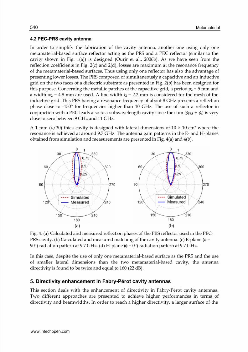
A 1 mm (λ /30) thick cavity is designed with lateral dimensions of 10 × 10 cm2 where theresonance is achieved at around 9.7 GHz. The antenna gain patterns in the E- and H-planesobtained from simulation and measurements are presented in Fig. 4(a) and 4(b).
(a) (b)
Fig. 4. (a) Calculated and measured reflection phases of the PRS reflector used in the PEC-
PRS cavity. (b) Calculated and measured matching of the cavity antenna. (c) E-plane (φ =
90°) radiation pattern at 9.7 GHz. (d) H-plane (φ = 0°) radiation pattern at 9.7 GHz.
In this case, despite the use of only one metamaterial-based surface as the PRS and the use
of smaller lateral dimensions than the two metamaterial-based cavity, the antenna
directivity is found to be twice and equal to 160 (22 dB).
5. Directivity enhancement in Fabry-Pérot cavity antennas
This section deals with the enhancement of directivity in Fabry-Pérot cavity antennas.
Two different approaches are presented to achieve higher performances in terms of
directivity and beamwidths. In order to reach a higher directivity, a larger surface of the
www.intechopen.com
7/16/2019 InTech-Metasurfaces for High Directivity Antenna Applications
http://slidepdf.com/reader/full/intech-metasurfaces-for-high-directivity-antenna-applications 9/25
Metasurfaces for High Directivity Antenna Applications 541
PRS must be illuminated. Therefore, a better distribution and confinement of the
electromagnetic energy must be produced in the cavity. For this purpose, two innovative
solutions can be considered. The first one is to shield the cavity by four metallic walls and
the second one is to feed the cavity by multiple primary sources. The two methods are
detailed below.
5.1 Metallic cavity antenna
The cavity antenna proposed in this section was designed at 2.46 GHz for point to point
radio communication links. The metallic cavity is composed of the feeding antenna’s PEC
ground plane and a metamaterial-based PRS as reflectors. Furthermore, four metallic walls
are also fixed on the lateral sides so as to enhance the directivity of the cavity antenna whilekeeping low lateral dimensions (Burokur et al., 2009a).
(a)
(b)
(c) (d)
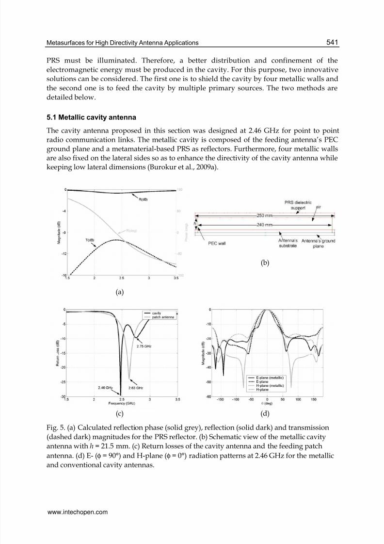
Fig. 5. (a) Calculated reflection phase (solid grey), reflection (solid dark) and transmission
(dashed dark) magnitudes for the PRS reflector. (b) Schematic view of the metallic cavity
antenna with h = 21.5 mm. (c) Return losses of the cavity antenna and the feeding patch
antenna. (d) E- (φ = 90°) and H-plane (φ = 0°) radiation patterns at 2.46 GHz for the metallic
and conventional cavity antennas.
www.intechopen.com
7/16/2019 InTech-Metasurfaces for High Directivity Antenna Applications
http://slidepdf.com/reader/full/intech-metasurfaces-for-high-directivity-antenna-applications 10/25
Metamaterial542
The inductive and capacitive grids of the metasurface are printed on the faces of an 8 mm
thick foam dielectric substrate (ε r = 1.45, tanδ = 0.0058). This thickness is sufficient enough
to provide a relatively smooth slope of the phase response, hence rendering themetamaterial less sensitive to fabrication tolerances. The capacitive grid is formed by 2-D
periodic metallic patches lattice (period p2 = 20 mm and width w2 = 18.8 mm) whereas theinductive grid is formed by a 2-D periodic mesh (line width l2 = 6 mm). The size of thedifferent patterns has been chosen in order to have the phase of the reflection coefficient
below 0° near 2.46 GHz while providing a sufficiently high reflectance (~90%). The
numerical results presented in Fig. 5(a) show firstly a resonance frequency of 2.38 GHz,
i.e. where the phase crosses 0°. Secondly, we can also note a pass-band behavior wherethe transmission level is relatively low (about –9.5 dB). Finally this figure shows a
reflection phase of –15° at 2.46 GHz.
The microstrip patch feeding source having dimensions 43 mm x 43 mm is designed on asimilar foam dielectric substrate of thickness 5 mm. The surface of the inductive and
capacitive grids forming the PRS has dimensions 200 mm × 200 mm, while the lateraldimensions of the dielectric board supporting the grids as well as that of the cavity have
been increased to 250 mm × 250 mm. However the lateral metallic walls are separated by adistance of 240 mm, as illustrated by the side view of the cavity antenna in Fig. 5(b). So with
a φ PRS = –15°, the thickness of the cavity is found to be h = 21.5 mm (< λ /5).The simulatedmetallic cavity presents a return loss of 22.8 dB at 2.46 GHz [Fig. 5(c)]. A second resonance is
observed at 2.75 GHz corresponding to the resonance of the feeding antenna. These tworesonances are situated at each side of that of the feeding patch alone due to the coupling
between the patch antenna and the FP cavity.
The calculated results [Fig. 5(d)] for the E- and H-plane radiation patterns show a directivity
of 15.21 dB. Compared to a similar cavity without metallic walls, an enhancement of about 3
dB and lower secondary lobes are achieved. To reach this same directivity without metallic
walls, we should have used a cavity with lateral dimensions close to 400 mm × 400 mm.
Also, the metallic cavity presents very low backward radiations (–24.3 dB) due to the energy
confinement by the lateral walls.
A prototype of the proposed cavity has been fabricated and measured (Fig. 6). However, the
responses measured with h = 21.5 mm have not shown a resonance as expected at 2.46 GHz
but at 2.49 GHz. This is due to the matching of the fabricated feeding patch antenna which
does not occur at 2.63 GHz as in simulation. Moreover, the responses of the PRS may also
present a shift in frequency which can be attributed to the manufacturing tolerances. Amodification on the thickness of the cavity has then been undertaken in order to achieve as
close as possible the calculated resonance frequency. Three other different thicknesses (h =
25 mm, h = 27.9 mm and h = 28.5 mm) have shown remarkable performances. The different
results are summarized in Table 1.
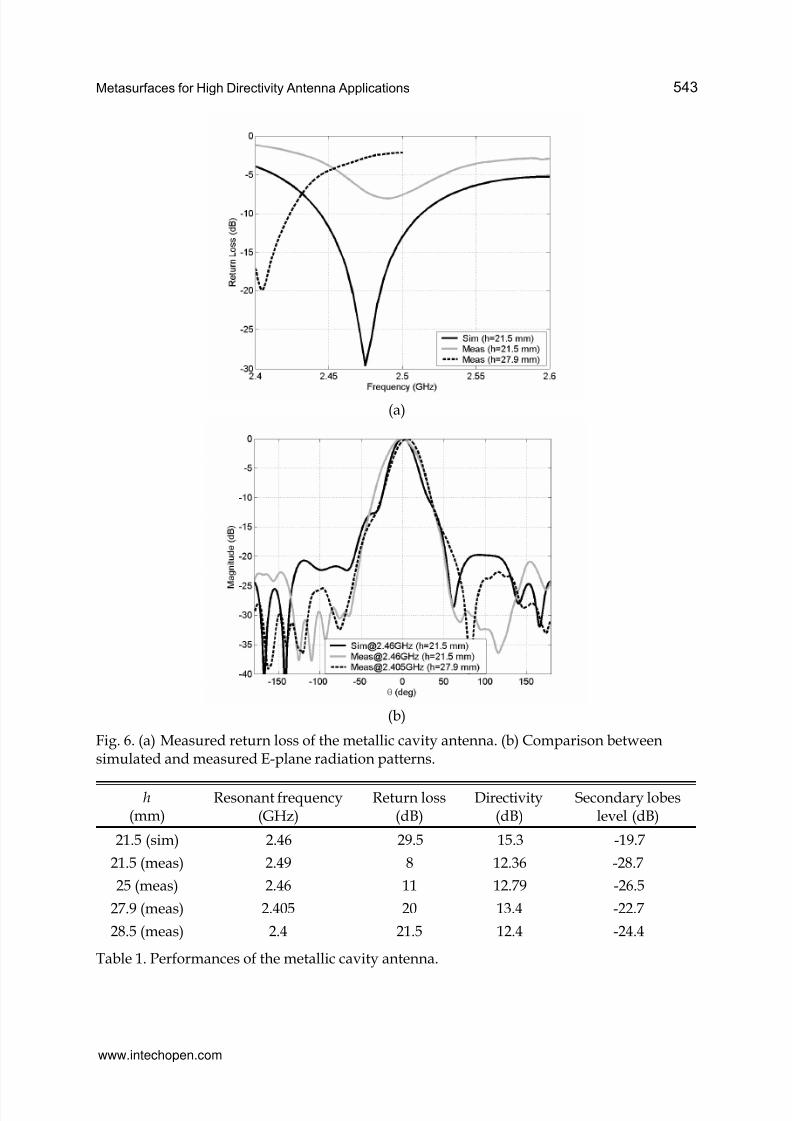
As the thickness increases, the resonance of the cavity antenna tends to lower frequencies.
For h = 25 mm, the measurements show a return loss of 11 dB and a directivity of 12.79 dB
with secondary lobes reaching a level of –26.5 dB. For h = 28.5 mm, the return loss is
enhanced to 21.5 dB at 2.405 GHz but the directivity falls to 12.4 dB. The best directivity
(13.4 dB) is observed at 2.405 GHz for h = 27.9 mm with secondary lobes level of -22.7 dB.
www.intechopen.com
7/16/2019 InTech-Metasurfaces for High Directivity Antenna Applications
http://slidepdf.com/reader/full/intech-metasurfaces-for-high-directivity-antenna-applications 11/25
Metasurfaces for High Directivity Antenna Applications 543
(a)
(b)
Fig. 6. (a) Measured return loss of the metallic cavity antenna. (b) Comparison betweensimulated and measured E-plane radiation patterns.
h (mm)
Resonant frequency(GHz)
Return loss(dB)
Directivity(dB)
Secondary lobeslevel (dB)
21.5 (sim) 2.46 29.5 15.3 -19.7
21.5 (meas) 2.49 8 12.36 -28.7
25 (meas) 2.46 11 12.79 -26.5
27.9 (meas) 2.405 20 13.4 -22.7
28.5 (meas) 2.4 21.5 12.4 -24.4
Table 1. Performances of the metallic cavity antenna.
www.intechopen.com
7/16/2019 InTech-Metasurfaces for High Directivity Antenna Applications
http://slidepdf.com/reader/full/intech-metasurfaces-for-high-directivity-antenna-applications 12/25
Metamaterial544
5.2 Multisource-fed cavity antenna
As stated earlier, the second method to reach higher directivity is based on the use ofmultiple primary sources in the cavity. Therefore in this section, the cavities operating near
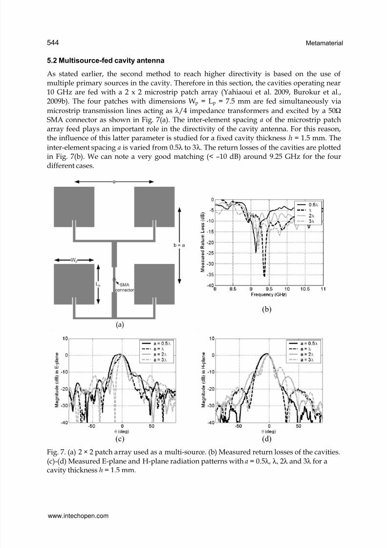
10 GHz are fed with a 2 x 2 microstrip patch array (Yahiaoui et al. 2009, Burokur et al.,2009b). The four patches with dimensions Wp = Lp = 7.5 mm are fed simultaneously via
microstrip transmission lines acting as λ /4 impedance transformers and excited by a 50Ω SMA connector as shown in Fig. 7(a). The inter-element spacing a of the microstrip patcharray feed plays an important role in the directivity of the cavity antenna. For this reason,the influence of this latter parameter is studied for a fixed cavity thickness h = 1.5 mm. The
inter-element spacing a is varied from 0.5λ to 3λ . The return losses of the cavities are plottedin Fig. 7(b). We can note a very good matching (< –10 dB) around 9.25 GHz for the fourdifferent cases.
(a)
(b)
(c)
(d)
Fig. 7. (a) 2 × 2 patch array used as a multi-source. (b) Measured return losses of the cavities.
(c)-(d) Measured E-plane and H-plane radiation patterns with a = 0.5λ , λ, 2λ and 3λ for acavity thickness h = 1.5 mm.
www.intechopen.com
7/16/2019 InTech-Metasurfaces for High Directivity Antenna Applications
http://slidepdf.com/reader/full/intech-metasurfaces-for-high-directivity-antenna-applications 13/25
Metasurfaces for High Directivity Antenna Applications 545
The measured E- and H-plane radiation patterns of the cavity antennas are presented in Fig.
7(c) and 7(d). For a = 0.5λ , a measured directivity of 19 dB is obtained at 8.93 GHz. Thisvalue is very close to that of a cavity fed by a single source (see for e.g. Ourir et al., 2006a,2006b). So, it is worth to note that conversely to classical antenna arrays, the directivity is
not doubled each time that the number of sources is doubled. For a = λ , a measureddirectivity of 20.9 dB is noted at 9.07 GHz, showing clearly an enhancement of 1.9 dB with
regard to the case a = 0.5λ . It is also very important to note that the sidelobes level of thepatch array is considerably reduced when embedded in the cavity. This effect is highlightedin Table 2 where the performances of cavities for the different inter-element spacing arepresented. 23.21 dB and 25.35 dB is respectively deduced from the measured planes for a =
2λ and a = 3λ . When the case a = 3λ is compared to a = 0.5λ , an increase of 6.35 dB isobtained for the directivity, which is comparable to an increase from a single patch element
to a 2 × 2 patch array. The measured sidelobes level are higher (~ –8dB in the H-plane) for
the case a = 3λ . However, this sidelobes level is still low compared to the sidelobes level of
the source alone. It is well known that an inter-element spacing of an array higher than λ leads to high sidelobes level and also to the apparition of grating lobes.
The directivity D of the cavity antennas can be calculated using D = 41253/(θ 1 × θ 2 ) where θ 1
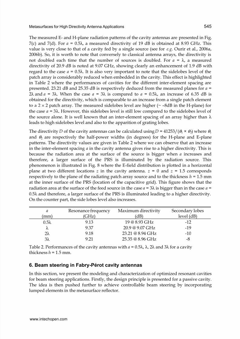
and θ 2 are respectively the half-power widths (in degrees) for the H-plane and E-planepatterns. The directivity values are given in Table 2 where we can observe that an increasein the inter-element spacing a in the cavity antenna gives rise to a higher directivity. This isbecause the radiation area at the surface of the source is bigger when a increases andtherefore, a larger surface of the PRS is illuminated by the radiation source. Thisphenomenon is illustrated in Fig. 8 where the E-field distribution is plotted in a horizontalplane at two different locations z in the cavity antenna. z = 0 and z = 1.5 corresponds
respectively to the plane of the radiating patch array source and to the thickness h = 1.5 mmat the inner surface of the PRS (location of the capacitive grid). This figure shows that the
radiation area at the surface of the feed source in the case a = 3λ is bigger than in the case a =
0.5λ and therefore, a larger surface of the PRS is illuminated leading to a higher directivity.On the counter part, the side lobes level also increases.
a (mm)
Resonance frequency(GHz)
Maximum directivity(dB)
Secondary lobeslevel (dB)
0.5λ 9.13 19 @ 8.93 GHz -12
λ 9.37 20.9 @ 9.07 GHz -19
2λ 9.18 23.21 @ 8.94 GHz -10
3λ 9.21 25.35 @ 8.96 GHz -8
Table 2. Performances of the cavity antennas with a = 0.5λ , λ, 2λ and 3λ for a cavitythickness h = 1.5 mm.
6. Beam steering in Fabry-Pérot cavity antennas
In this section, we present the modeling and characterization of optimized resonant cavitiesfor beam steering applications. Firstly, the design principle is presented for a passive cavity.The idea is then pushed further to achieve controllable beam steering by incorporatinglumped elements in the metasurface reflector.
www.intechopen.com
7/16/2019 InTech-Metasurfaces for High Directivity Antenna Applications
http://slidepdf.com/reader/full/intech-metasurfaces-for-high-directivity-antenna-applications 14/25
Metamaterial546
Fig. 8. E-field distribution in a horizontal plane in the cavity antenna for a = 0.5λ and a = 3λ .
6.1 Passive beam steering
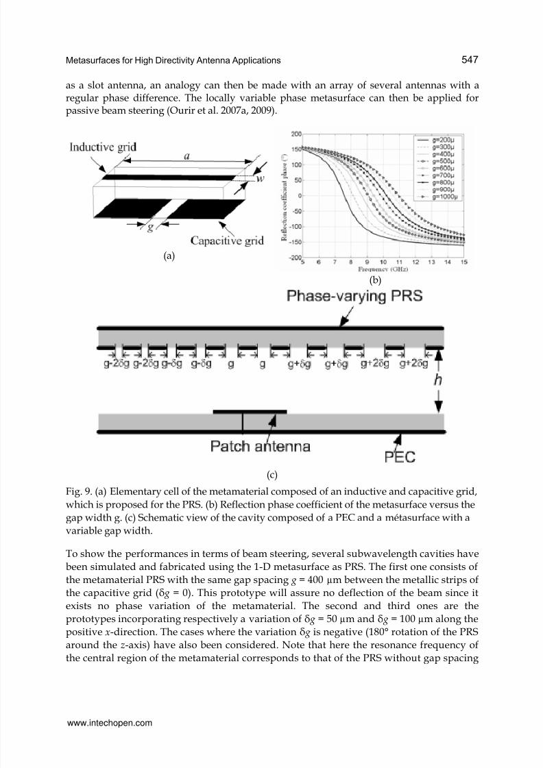
Since the beam steering operation is presented in only one radiation plane, the metasurfaceused is composed of a 1-D array of copper strips etched on each face of a dielectric substrateas shown in Fig. 9(a).
We shall note that the gap spacing g in the capacitive grid plays a crucial role in determiningthe capacitance and therefore the resonance frequency of the metasurface. By changing g and keeping all the other geometric parameters unchanged, the capacitance of themetamaterial will also vary. As a consequence, the phases of the computed reflectioncoefficients vary. This behavior is illustrated by the numerical results shown in Fig. 9(b). Wecan note that the variation of g accounts for the shift of the resonance frequency. An increasein the value of g causes a decrease in the value of the capacitance created between two cells,and finally a shift of the resonance towards higher frequencies. At a particular frequency,the phase of the metasurface increases with an increase in the gap spacing. The study on thevariation of g shows that it is possible to design a PRS with a continuous variation of the gap g, resulting in a local variation of the phase characteristics (Fig. 9(c)). If we consider each gap
www.intechopen.com
7/16/2019 InTech-Metasurfaces for High Directivity Antenna Applications
http://slidepdf.com/reader/full/intech-metasurfaces-for-high-directivity-antenna-applications 15/25
Metasurfaces for High Directivity Antenna Applications 547
as a slot antenna, an analogy can then be made with an array of several antennas with aregular phase difference. The locally variable phase metasurface can then be applied forpassive beam steering (Ourir et al. 2007a, 2009).
(a)
(b)
(c)
Fig. 9. (a) Elementary cell of the metamaterial composed of an inductive and capacitive grid,
which is proposed for the PRS. (b) Reflection phase coefficient of the metasurface versus the
gap width g. (c) Schematic view of the cavity composed of a PEC and a métasurface with a
variable gap width.
To show the performances in terms of beam steering, several subwavelength cavities have
been simulated and fabricated using the 1-D metasurface as PRS. The first one consists of
the metamaterial PRS with the same gap spacing g = 400 µm between the metallic strips of
the capacitive grid ( g = 0). This prototype will assure no deflection of the beam since it
exists no phase variation of the metamaterial. The second and third ones are the
prototypes incorporating respectively a variation of g = 50 µm and g = 100 µm along the
positive x-direction. The cases where the variation g is negative (180° rotation of the PRS
around the z-axis) have also been considered. Note that here the resonance frequency of
the central region of the metamaterial corresponds to that of the PRS without gap spacing
www.intechopen.com
7/16/2019 InTech-Metasurfaces for High Directivity Antenna Applications
http://slidepdf.com/reader/full/intech-metasurfaces-for-high-directivity-antenna-applications 16/25
Metamaterial548
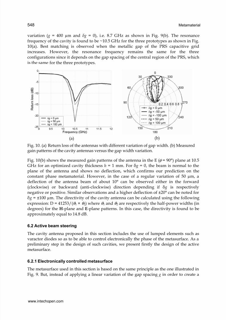
variation ( g = 400 µm and δ g = 0), i.e. 8.7 GHz as shown in Fig. 9(b). The resonance
frequency of the cavity is found to be ~10.5 GHz for the three prototypes as shown in Fig.
10(a). Best matching is observed when the metallic gap of the PRS capacitive grid
increases. However, the resonance frequency remains the same for the three
configurations since it depends on the gap spacing of the central region of the PRS, whichis the same for the three prototypes.
(a) (b)
Fig. 10. (a) Return loss of the antennas with different variation of gap width. (b) Measuredgain patterns of the cavity antennas versus the gap width variation.
Fig. 10(b) shows the measured gain patterns of the antenna in the E (φ = 90°) plane at 10.5GHz for an optimized cavity thickness h = 1 mm. For g = 0, the beam is normal to the
plane of the antenna and shows no deflection, which confirms our prediction on theconstant phase metamaterial. However, in the case of a regular variation of 50 µm, a
deflection of the antenna beam of about 10° can be observed either in the forward
(clockwise) or backward (anti-clockwise) direction depending if g is respectively
negative or positive. Similar observations and a higher deflection of ±20° can be noted for
g = ±100 µm. The directivity of the cavity antenna can be calculated using the following
expression: D = 41253/(θ 1 × θ 2) where θ 1 and θ 2 are respectively the half-power widths (indegrees) for the H-plane and E-plane patterns. In this case, the directivity is found to be
approximately equal to 14.8 dB.
6.2 Active beam steering
The cavity antenna proposed in this section includes the use of lumped elements such asvaractor diodes so as to be able to control electronically the phase of the metasurface. As apreliminary step in the design of such cavities, we present firstly the design of the activemetasurface.
6.2.1 Electronically controlled metasurface
The metasurface used in this section is based on the same principle as the one illustrated in
Fig. 9. But, instead of applying a linear variation of the gap spacing g in order to create a
www.intechopen.com
7/16/2019 InTech-Metasurfaces for High Directivity Antenna Applications
http://slidepdf.com/reader/full/intech-metasurfaces-for-high-directivity-antenna-applications 17/25
Metasurfaces for High Directivity Antenna Applications 549
locally variable phase, we now use active components to make the phase of the metasurface
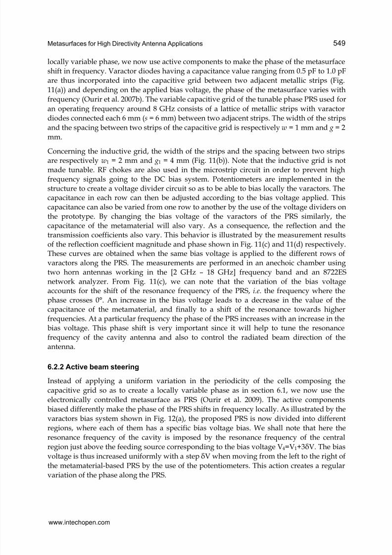
shift in frequency. Varactor diodes having a capacitance value ranging from 0.5 pF to 1.0 pF
are thus incorporated into the capacitive grid between two adjacent metallic strips (Fig.
11(a)) and depending on the applied bias voltage, the phase of the metasurface varies with
frequency (Ourir et al. 2007b). The variable capacitive grid of the tunable phase PRS used foran operating frequency around 8 GHz consists of a lattice of metallic strips with varactor
diodes connected each 6 mm (s = 6 mm) between two adjacent strips. The width of the strips
and the spacing between two strips of the capacitive grid is respectively w = 1 mm and g = 2
mm.
Concerning the inductive grid, the width of the strips and the spacing between two stripsare respectively w1 = 2 mm and g1 = 4 mm (Fig. 11(b)). Note that the inductive grid is not
made tunable. RF chokes are also used in the microstrip circuit in order to prevent high
frequency signals going to the DC bias system. Potentiometers are implemented in the
structure to create a voltage divider circuit so as to be able to bias locally the varactors. Thecapacitance in each row can then be adjusted according to the bias voltage applied. This
capacitance can also be varied from one row to another by the use of the voltage dividers on
the prototype. By changing the bias voltage of the varactors of the PRS similarly, thecapacitance of the metamaterial will also vary. As a consequence, the reflection and the
transmission coefficients also vary. This behavior is illustrated by the measurement results
of the reflection coefficient magnitude and phase shown in Fig. 11(c) and 11(d) respectively.These curves are obtained when the same bias voltage is applied to the different rows of
varactors along the PRS. The measurements are performed in an anechoic chamber using
two horn antennas working in the [2 GHz – 18 GHz] frequency band and an 8722ES
network analyzer. From Fig. 11(c), we can note that the variation of the bias voltage
accounts for the shift of the resonance frequency of the PRS, i.e. the frequency where thephase crosses 0°. An increase in the bias voltage leads to a decrease in the value of thecapacitance of the metamaterial, and finally to a shift of the resonance towards higher
frequencies. At a particular frequency the phase of the PRS increases with an increase in the
bias voltage. This phase shift is very important since it will help to tune the resonance
frequency of the cavity antenna and also to control the radiated beam direction of the
antenna.
6.2.2 Active beam steering
Instead of applying a uniform variation in the periodicity of the cells composing the
capacitive grid so as to create a locally variable phase as in section 6.1, we now use theelectronically controlled metasurface as PRS (Ourir et al. 2009). The active components
biased differently make the phase of the PRS shifts in frequency locally. As illustrated by the
varactors bias system shown in Fig. 12(a), the proposed PRS is now divided into different
regions, where each of them has a specific bias voltage bias. We shall note that here the
resonance frequency of the cavity is imposed by the resonance frequency of the central
region just above the feeding source corresponding to the bias voltage V4=V1+3V. The bias
voltage is thus increased uniformly with a step V when moving from the left to the right of
the metamaterial-based PRS by the use of the potentiometers. This action creates a regular
variation of the phase along the PRS.
www.intechopen.com
7/16/2019 InTech-Metasurfaces for High Directivity Antenna Applications
http://slidepdf.com/reader/full/intech-metasurfaces-for-high-directivity-antenna-applications 18/25
Metamaterial550
(a) (b)
(c)
(d)
Fig. 11. (a) Electronically phase-varying metasurface. (a) Capacitive grid incorporatingvaractors and voltage dividers. (b) Inductive grid. (c) Measured magnitude and (d)measured phase of the reflection coefficient versus bias voltage of the varicaps.
The first configuration studied here is the antenna cavity based on the metamaterial PRS
with the same null bias voltage for all the varactors. This configuration will assure no
deflection of the beam since it exists no phase variation of the metamaterial. The second and
third configurations are prototypes incorporating respectively a variation of V = 0.2 V and
V = 0.3 V along the positive x-direction. The cases where the variation V is negative (180°
rotation of the PRS around the z-axis) have also been considered.
Fig. 12(b) shows the gain patterns of the antenna in the E-plane (φ = 90°) at 7.9 GHz for the
optimized cavity. For V = 0 V, the beam is normal to the plane of the antenna and shows nodeflection, which confirms our prediction on the constant phase metamaterial. However, in
the case of a regular variation of V = 0.2 V, a deflection of the antenna beam of about 7° can
be observed either in the forward or backward direction depending if V is respectively
negative or positive. Similar observations and a higher deflection can be noted forrespectively V = 0.3 V and V = -0.3 V. This figure illustrates very clearly the control of the
radiation pattern of the antenna by the bias voltage of the varactors. The direction of theradiation beam depends of the direction of the variation of the bias of the varactors. If we
www.intechopen.com
7/16/2019 InTech-Metasurfaces for High Directivity Antenna Applications
http://slidepdf.com/reader/full/intech-metasurfaces-for-high-directivity-antenna-applications 19/25
Metasurfaces for High Directivity Antenna Applications 551
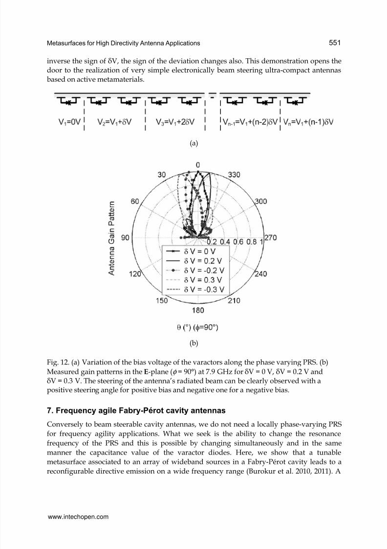
inverse the sign of V, the sign of the deviation changes also. This demonstration opens thedoor to the realization of very simple electronically beam steering ultra-compact antennas
based on active metamaterials.
(a)
(b)
Fig. 12. (a) Variation of the bias voltage of the varactors along the phase varying PRS. (b)
Measured gain patterns in the E-plane (φ = 90°) at 7.9 GHz for V = 0 V, V = 0.2 V and
V = 0.3 V. The steering of the antenna’s radiated beam can be clearly observed with apositive steering angle for positive bias and negative one for a negative bias.
7. Frequency agile Fabry-Pérot cavity antennas
Conversely to beam steerable cavity antennas, we do not need a locally phase-varying PRS
for frequency agility applications. What we seek is the ability to change the resonance
frequency of the PRS and this is possible by changing simultaneously and in the same
manner the capacitance value of the varactor diodes. Here, we show that a tunable
metasurface associated to an array of wideband sources in a Fabry-Pérot cavity leads to a
reconfigurable directive emission on a wide frequency range (Burokur et al. 2010, 2011). A
www.intechopen.com
7/16/2019 InTech-Metasurfaces for High Directivity Antenna Applications
http://slidepdf.com/reader/full/intech-metasurfaces-for-high-directivity-antenna-applications 20/25
Metamaterial552
similar electronically controlled PRS as the one shown in Fig. 11(a) is designed to operate
near 2 GHz in base station antennas for mobile phone communication systems. The primary
source of the cavity is a wideband microstrip patch antenna designed to cover 1.8 GHz – 2.7
GHz frequency range and therefore to illuminate the PRS at any frequency within this
range. This patch antenna is electromagnetically coupled to an L-probe which itself isconnected to a coaxial connector. Simulations have shown a good matching (return loss < 10
dB) from 1.8 GHz to 2.7 GHz.
To demonstrate experimentally the mechanism for reconfigurable directive emissions from a
metamaterial-based FP cavity, a prototype having dimensions 400*400 mm2 (approximately
3λ *3λ ) has been fabricated and tested. As it has been shown in section 5.2, the directivity is
drastically enhanced when a cavity is fed by judiciously spaced multiple sources since a
larger surface of the PRS is illuminated, and therefore the size of the effective radiating
aperture of the cavity antenna is increased. Four elementary sources constituting a 2 x 2
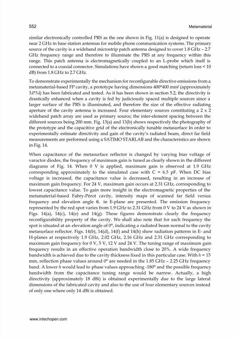
wideband patch array are used as primary source; the inter-element spacing between thedifferent sources being 200 mm. Fig. 13(a) and 13(b) shows respectively the photography of
the prototype and the capacitive grid of the electronically tunable metasurface In order to
experimentally estimate directivity and gain of the cavity’s radiated beam, direct far field
measurements are performed using a SATIMO STARLAB and the characteristics are shown
in Fig. 14.
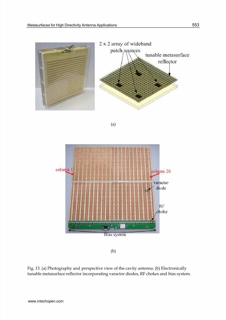
When capacitance of the metasurface reflector is changed by varying bias voltage of
varactor diodes, the frequency of maximum gain is tuned as clearly shown in the different
diagrams of Fig. 14. When 0 V is applied, maximum gain is observed at 1.9 GHz
corresponding approximately to the simulated case with C = 6.5 pF. When DC bias
voltage is increased, the capacitance value is decreased, resulting in an increase ofmaximum gain frequency. For 24 V, maximum gain occurs at 2.31 GHz, corresponding to
lowest capacitance value. To gain more insight in the electromagnetic properties of the
metamaterial-based Fabry-Pérot cavity, intensity maps of scanned far field versus
frequency and elevation angle θ, in E-plane are presented. The emission frequency
represented by the red spot varies from 1.9 GHz to 2.31 GHz from 0 V to 24 V as shown in
Figs. 14(a), 14(c), 14(e) and 14(g). These figures demonstrate clearly the frequency
reconfigurability property of the cavity. We shall also note that for each frequency the
spot is situated at an elevation angle of 0°, indicating a radiated beam normal to the cavity
metasurface reflector. Figs. 14(b), 14(d), 14(f) and 14(h) show radiation patterns in E- and
H-planes at respectively 1.9 GHz, 2.02 GHz, 2.16 GHz and 2.31 GHz corresponding tomaximum gain frequency for 0 V, 5 V, 12 V and 24 V. The tuning range of maximum gain
frequency results in an effective operation bandwidth close to 20%. A wide frequency
bandwidth is achieved due to the cavity thickness fixed in this particular case. With h = 15
mm, reflection phase values around 0° are needed in the 1.85 GHz – 2.25 GHz frequency
band. A lower h would lead to phase values approaching -180° and the possible frequency
bandwidth from the capacitance tuning range would be narrow. Actually, a high
directivity (approximately 18 dBi) is obtained experimentally due to the large lateral
dimensions of the fabricated cavity and also to the use of four elementary sources instead
of only one where only 14 dBi is obtained.
www.intechopen.com
7/16/2019 InTech-Metasurfaces for High Directivity Antenna Applications
http://slidepdf.com/reader/full/intech-metasurfaces-for-high-directivity-antenna-applications 21/25
Metasurfaces for High Directivity Antenna Applications 553
(a)
(b)
Fig. 13. (a) Photography and perspective view of the cavity antenna. (b) Electronically
tunable metasurface reflector incorporating varactor diodes, RF chokes and bias system.
www.intechopen.com
7/16/2019 InTech-Metasurfaces for High Directivity Antenna Applications
http://slidepdf.com/reader/full/intech-metasurfaces-for-high-directivity-antenna-applications 22/25
Metamaterial554
Fig. 14. Far field intensity maps versus frequency and elevation angle in E-plane and
measured radiation patterns in E- and H-planes at maximum gain frequency for different
bias voltage applied : (a)-(b) 0 V – 1.9 GHz, (c)-(d) 5 V – 2.02 GHz, (e)-(f) 12 V – 2.16 GHz,and (g)-(h) 24 V – 2.31 GHz.
www.intechopen.com
7/16/2019 InTech-Metasurfaces for High Directivity Antenna Applications
http://slidepdf.com/reader/full/intech-metasurfaces-for-high-directivity-antenna-applications 23/25
Metasurfaces for High Directivity Antenna Applications 555
8. Conclusion
To conclude, we have presented various aspects of reflex-cavity antennas: low-profile, high
gain, beam steering and frequency agility. For each aspect, numerical calculations together
with measurements have been presented. The development of these works has enabled topromote the interesting characteristics of metamaterial-based surfaces. Variable phase
metasurfaces compared to conventional PEC and AMC surfaces have also shown their
usefulness in reconfigurability applications. Further studies are actually performed totranspose the reflex-cavity antenna concept to industrial applications in various domains
such as telecommunications, aeronautical, transport and housing.
9. Acknowledgements
The authors are very grateful to the French National Research Agency (ANR) for thefinancial support of the METABIP Project. These works have also been made possible by the
partial financial support of the Eureka TELEMAC project. We would like also to thank ourpartners P. Ratajczak and J.-P. Daniel for the fabrication and characterization of antennaprototypes.
10. References
Akalin, T., Danglot, J., Vanbesien, O. & Lippens, D. (2002). A highly directive dipole antennaembedded in a Fabry–Perot-type cavity. IEEE Microw. Wireless Component Lett.,
Vol.12, No.2, (February 2002), pp. 48-50, ISSN 1531-1309.Burokur, S.N., Latrach, M. & Toutain, S. (2005). Theoretical investigation of a circular patch
antenna in the presence of a Left-Handed Medium. IEEE Antennas Wireless Propag.
Lett., Vol.4, (June 2005), pp. 183-186, ISSN 1536-1225.Burokur, S.N., Ourir, A., Daniel, J.-P., Ratajczak, P. & de Lustrac, A. (2009a). Highly directive
ISM band cavity antenna using a bi-layered metasurface reflector. Microwave Opt.Technol. Lett., Vol.51, No.6, (June 2009), pp. 1393-1396, ISSN 0895-2477.
Burokur, S.N., Yahiaoui, R. & de Lustrac, A. (2009b). Subwavelength metamaterial-basedresonant cavities fed by multiple sources for high directivity. Microwave Opt.
Technol. Lett., Vol.51, No.8, (August 2009), pp. 1883-1888, ISSN 0895-2477.Burokur, S.N., Daniel, J.-P., Ratajczak, P. & de Lustrac, A. (2010). Tunable bilayered
metasurface for frequency reconfigurable directive emissions. Appl. Phys. Lett.,Vol.97, No.6, (August 2010), 064101, ISSN 0003-6951.
Burokur, S.N., Daniel, J.-P., Ratajczak, P. & de Lustrac, A. (2011). Low-profile frequencyagile directive antenna based on an active metasurface. Microwave Opt. Technol.
Lett., Vol.53, No.10, (October 2011), pp. 2291-2295, ISSN 0895-2477.Cheype, C., Serier, C., Thèvenot, M., Monédière, T., Reinex, A. & Jecko, B. (2002). An
electromagnetic bandgap resonator antenna. IEEE Trans. Antennas Propag., Vol.50,No.9, (September 2002), pp. 1285-1290, ISSN 0018-926X.
Enoch, S., Tayeb, G., Sabouroux, P., Guérin, N. & Vincent, P. (2002). A metamaterial fordirective emission. Phys. Rev. Lett., Vol.89, No.21, (November 2002), 213902, ISSN0031-9007.
www.intechopen.com
7/16/2019 InTech-Metasurfaces for High Directivity Antenna Applications
http://slidepdf.com/reader/full/intech-metasurfaces-for-high-directivity-antenna-applications 24/25
Metamaterial556
Feresidis, A.P., Goussetis, G., Wang, S. & Vardaxoglou, J.C. (2005). Artificial MagneticConductor Surfaces and their application to low-profile high-gain planar antennas.IEEE Trans. Antennas Propag., Vol.53, No.1, (January 2005), pp. 209-215, ISSN 0018-926X.
Jackson, D.R. & Alexópoulos, N.G. (1985). Gain enhancement methods for printed circuitantennas. IEEE Trans. Antennas Propag., Vol.AP-33, No.9, (September 1985), pp. 976-987, ISSN 0018-926X.
Nakano, H., Ikeda, M., Hitosugi, K. & Yamauchi, J. (2004). A spiral antenna sandwiched bydielectric layers. IEEE Trans. Antennas Propag., Vol.52, No.6, (June 2004), pp. 1417-1423, ISSN 0018-926X.
Ourir, A., de Lustrac, A. & Lourtioz, J.-M. (2006a). All-metamaterial-based subwavelength
cavities (λ /60) for ultrathin directive antennas. Appl. Phys. Lett., Vol.88, No.8,(February 2006), 084103, ISSN 0003-6951.
Ourir, A., de Lustrac, A. & Lourtioz, J.-M. (2006b). Optimization of metamaterial basedsubwavelength cavities for ultracompact directive antennas. Microwave Opt.Technol. Lett., Vol.48, No.12, (December 2006), pp. 2573-2577, ISSN 0895-2477.
Ourir, A., Burokur, S.N. & de Lustrac, A. (2007a). Phase-varying metamaterial for compactsteerable directive antennas. Electron. Lett., Vol.43, No.9, (April 2007), pp. 493-494,ISSN 0013-5194.
Ourir, A., Burokur, S.N. & de Lustrac, A. (2007b). Electronically reconfigurable metamaterialfor compact directive cavity antennas. Electron. Lett., Vol.43, No.13, (June 2007), pp.698-700, ISSN 0013-5194.
Ourir, A., Burokur, S.N., Yahiaoui, R. & de Lustrac, A. (2009). Directive metamaterial-basedsubwavelength resonant cavity antennas – Applications for beam steering. C. R.Physique, Vol.10, No.5, (June 2009), pp. 414-422, ISSN 1631-0705.
Sievenpiper, D., Zhang, L., Broas, R.F.J., Alexópoulos, N.G. & Yablonovitch, E. (1999). High-Impedance Electromagnetic Surfaces with a forbidden frequency band. IEEE Trans. Microw. Theory Tech., Vol.47, No.11, (November 1999), pp. 2059-2074, ISSN 0018-9480.
Temelkuran, B., Bayindir, M., Ozbay, E., Biswas, R., Sigalas, M.M., Tuttle, G. & Ho, K.M.(2000). Photonic crystal-based resonant antenna with a very high directivity. J. Appl.Phys., Vol.87, No.1, (January 2000), pp. 603-605, ISSN 0021-8979.
Trentini, G.V. (1956). Partially reflecting sheet arrays. IRE Trans. Antennas Propag., Vol.4,No.4, (October 1956), pp. 666-671, ISSN 0096-1973.
Yahiaoui, R., Burokur, S.N. & de Lustrac, A. (2009). Enhanced directivity of ultra-thinmetamaterial-based cavity antenna fed by multisource. Electron. Lett., Vol.45, No.16,
(July 2009), pp. 814-816, ISSN 0013-5194.Zhou, L., Li, H., Qin, Y., Wei, Z. & Chan, C.T. (2005). Directive emissions from
subwavelength metamaterial-based cavities. Appl. Phys. Lett., Vol.86, No.10, (March2005), 101101, ISSN 0003-6951.
www.intechopen.com
7/16/2019 InTech-Metasurfaces for High Directivity Antenna Applications
http://slidepdf.com/reader/full/intech-metasurfaces-for-high-directivity-antenna-applications 25/25
Metamaterial
Edited by Dr. Xun-Ya Jiang
ISBN 978-953-51-0591-6
Hard cover, 620 pages
Publisher InTech
Published online 16, May, 2012
Published in print edition May, 2012
InTech Europe
University Campus STeP Ri
Slavka Krautzeka 83/A
51000 Rijeka, Croatia
Phone: +385 (51) 770 447
Fax: +385 (51) 686 166
www.intechopen.com
InTech China
Unit 405, Office Block, Hotel Equatorial Shanghai
No.65, Yan An Road (West), Shanghai, 200040, China
Phone: +86-21-62489820
Fax: +86-21-62489821
In-depth analysis of the theory, properties and description of the most potential technological applications of
metamaterials for the realization of novel devices such as subwavelength lenses, invisibility cloaks, dipole and
reflector antennas, high frequency telecommunications, new designs of bandpass filters, absorbers and
concentrators of EM waves etc. In order to create a new devices it is necessary to know the main
electrodynamical characteristics of metamaterial structures on the basis of which the device is supposed to be
created. The electromagnetic wave scattering surfaces built with metamaterials are primarily based on the
ability of metamaterials to control the surrounded electromagnetic fields by varying their permeability and
permittivity characteristics. The book covers some solutions for microwave wavelength scales as well as
exploitation of nanoscale EM wavelength such as visible specter using recent advances of nanotechnology, for
instance in the field of nanowires, nanopolymers, carbon nanotubes and graphene. Metamaterial is suitable for
scholars from extremely large scientific domain and therefore given to engineers, scientists, graduates and
other interested professionals from photonics to nanoscience and from material science to antenna
engineering as a comprehensive reference on this artificial materials of tomorrow.
How to reference
In order to correctly reference this scholarly work, feel free to copy and paste the following:
Shah Nawaz Burokur, Abdelwaheb Ourir, André de Lustrac and Riad Yahiaoui (2012). Metasurfaces for High
Directivity Antenna Applications, Metamaterial, Dr. Xun-Ya Jiang (Ed.), ISBN: 978-953-51-0591-6, InTech,
Available from: http://www.intechopen.com/books/metamaterial/metasurfaces-for-high-directivity-antenna-
applications