Embed Size (px)
Citation preview
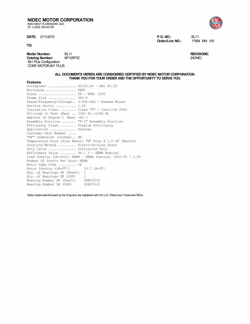
NIDEC MOTOR CORPORATION8050 WEST FLORISSANT AVE.ST. LOUIS, MO 63136
DATE: 2/11/2015 P.O. NO.: BL11 Order/Line NO.: 17684 MN 100TO: Model Number: BL11Catalog Number: 8P125P3C 841 Plus Configuration CONF,MOTOR,841 PLUS
REVISIONS:(NONE)
ALL DOCUMENTS HEREIN ARE CONSIDERED CERTIFIED BY NIDEC MOTOR CORPORATION.
THANK YOU FOR YOUR ORDER AND THE OPPORTUNITY TO SERVE YOU.Features:Horsepower .............. 00125.00 ~ KW: 93.25Enclosure ............... TEFCPoles ................... 06 ~ RPM: 1200Frame Size .............. 445~TPhase/Frequency/Voltage.. 3~060~460 ~ Random WoundService Factor .......... 1.15Insulation Class ........ Class "F" ~ Insulife 2000Altitude In Feet (Max) .. 3300 Ft.(1000 M)Ambient In Degree C (Max) +40 CAssembly Position ....... "F-1" Assembly PositionEfficiency Class ........ Premium EfficiencyApplication ............. UnknownCustomer Part Number ...."AK" Dimension (Inches).. NATemperature Rise (Sine Wave): "B" Rise @ 1.0 SF (Resist)Starting Method ......... Direct-On-Line StartDuty Cycle .............. Continuous DutyEfficiency Value ........ 94.1 % ~ NEMA NominalLoad Inertia (lb-ft2): NEMA ~ NEMA Inertia: 1452.00 ~ 1.00Number Of Starts Per Hour: NEMAMotor Type Code ......... CERotor Inertia (LB-FT²) 53.7 LB-FT²Qty. of Bearings PE (Shaft) 1Qty. of Bearings SE (OPP) 1Bearing Number PE (Shaft) 90BC03J3Bearing Number SE (OPP) 65BC03J3
Nidec trademarks followed by the ® symbol are registered with the U.S. Patent and Trademark Office.
NIDEC MOTOR CORPORATION8050 WEST FLORISSANT AVE.ST. LOUIS, MO 63136
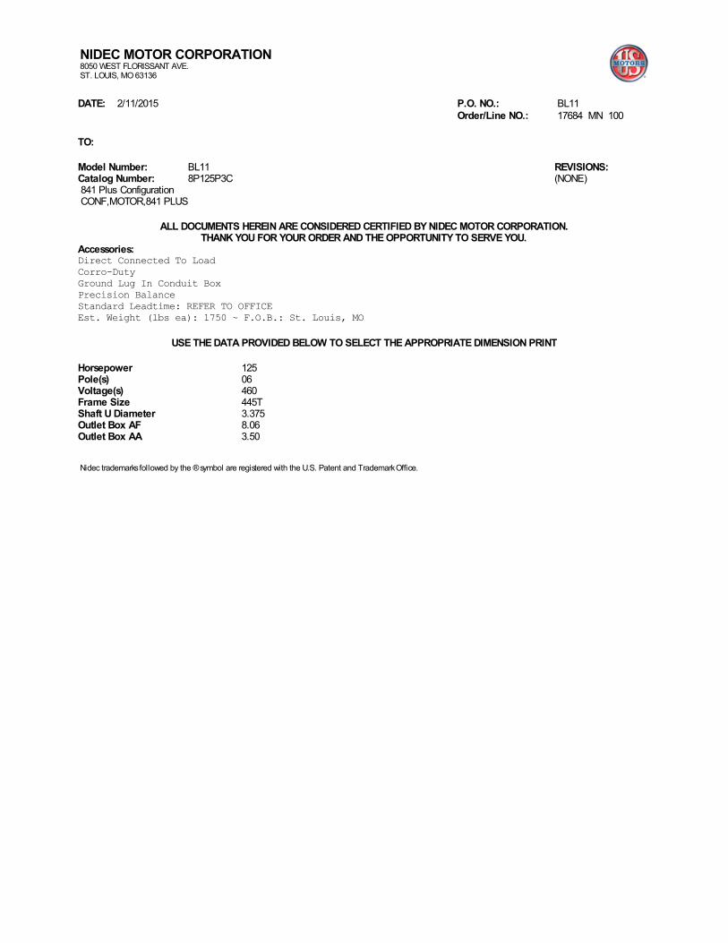
DATE: 2/11/2015 P.O. NO.: BL11 Order/Line NO.: 17684 MN 100 TO: Model Number: BL11Catalog Number: 8P125P3C 841 Plus Configuration CONF,MOTOR,841 PLUS
REVISIONS:(NONE)
ALL DOCUMENTS HEREIN ARE CONSIDERED CERTIFIED BY NIDEC MOTOR CORPORATION.
THANK YOU FOR YOUR ORDER AND THE OPPORTUNITY TO SERVE YOU.Accessories:Direct Connected To LoadCorro-DutyGround Lug In Conduit BoxPrecision BalanceStandard Leadtime: REFER TO OFFICEEst. Weight (lbs ea): 1750 ~ F.O.B.: St. Louis, MO
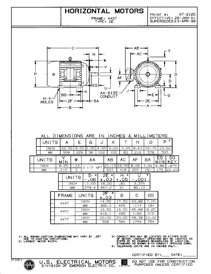
USE THE DATA PROVIDED BELOW TO SELECT THE APPROPRIATE DIMENSION PRINT Horsepower 125Pole(s) 06Voltage(s) 460Frame Size 445TShaft U Diameter 3.375Outlet Box AF 8.06Outlet Box AA 3.50
Nidec trademarks followed by the ® symbol are registered with the U.S. Patent and Trademark Office.
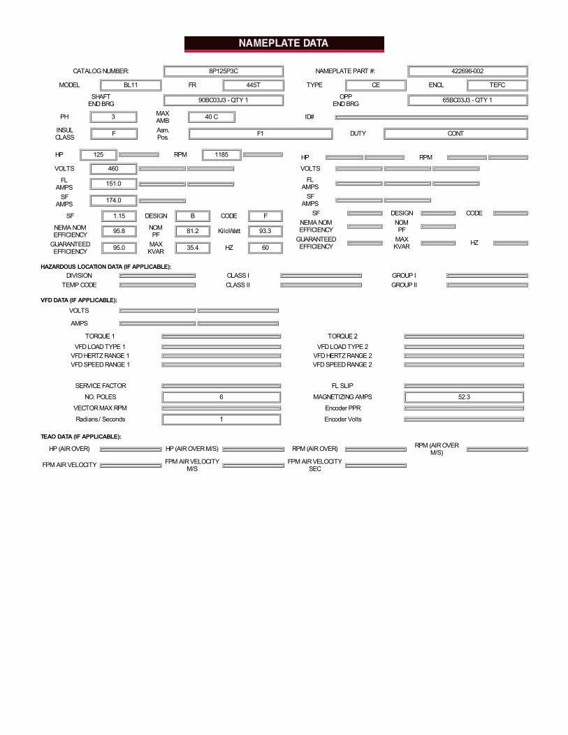
CATALOG NUMBER: 8P125P3C NAMEPLATE PART #: 422696-002
MODEL BL11 FR 445T TYPE CE ENCL TEFC
SHAFTEND BRG 90BC03J3 - QTY 1 OPP
END BRG 65BC03J3 - QTY 1
PH 3 MAXAMB 40 C ID#
INSULCLASS F Asm.
Pos. F1 DUTY CONT
HP 125 RPM 1185
VOLTS 460 FL
AMPS 151.0 SF
AMPS 174.0 SF 1.15 DESIGN B CODE F
NEMA NOMEFFICIENCY 95.8 NOM
PF 81.2 KiloWatt 93.3
GUARANTEEDEFFICIENCY 95.0 MAX
KVAR 35.4 HZ 60
HP RPM
VOLTS FL
AMPS SF
AMPS SF DESIGN CODE
NEMA NOMEFFICIENCY
NOMPF
GUARANTEEDEFFICIENCY
MAXKVAR HZ
HAZARDOUS LOCATION DATA (IF APPLICABLE):DIVISION CLASS I GROUP I
TEMP CODE CLASS II GROUP II
VFD DATA (IF APPLICABLE):
VOLTS AMPS
TORQUE 1 TORQUE 2 VFD LOAD TYPE 1 VFD LOAD TYPE 2
VFD HERTZ RANGE 1 VFD HERTZ RANGE 2VFD SPEED RANGE 1 VFD SPEED RANGE 2
SERVICE FACTOR FL SLIP
NO. POLES 6 MAGNETIZING AMPS 52.3
VECTOR MAX RPM Encoder PPR
Radians / Seconds 1 Encoder Volts
TEAO DATA (IF APPLICABLE):
HP (AIR OVER) HP (AIR OVER M/S) RPM (AIR OVER) RPM (AIR OVERM/S)
FPM AIR VELOCITY FPM AIR VELOCITYM/S
FPM AIR VELOCITYSEC
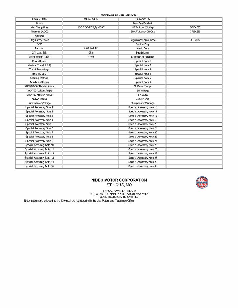
ADDITIONAL NAMEPLATE DATA: Decal / Plate WD=499495 Customer PN
Notes Non Rev Ratchet Max Temp Rise 80C RISE/[email protected] OPP/Upper Oil Cap GREASE Thermal (WDG) SHAFT/Lower Oil Cap GREASE
Altitude Regulatory Notes Regulatory Compliance CC 030A
COS Marine Duty Balance 0.05 IN/SEC Arctic Duty
3/4 Load Eff. 96.0 Inrush Limit Motor Weight (LBS) 1750 Direction of Rotation
Sound Level Special Note 1 Vertical Thrust (LBS) Special Note 2 Thrust Percentage Special Note 3
Bearing Life Special Note 4 Starting Method Special Note 5 Number of Starts Special Note 6
200/208V 60Hz Max Amps SH Max. Temp. 190V 50 hz Max Amps SH Voltage 380V 50 Hz Max Amps SH Watts
NEMA Inertia Load Inertia Sumpheater Voltage Sumpheater Wattage
Special Accessory Note 1 Special Accessory Note 16 Special Accessory Note 2 Special Accessory Note 17 Special Accessory Note 3 Special Accessory Note 18 Special Accessory Note 4 Special Accessory Note 19 Special Accessory Note 5 Special Accessory Note 20 Special Accessory Note 6 Special Accessory Note 21 Special Accessory Note 7 Special Accessory Note 22 Special Accessory Note 8 Special Accessory Note 23 Special Accessory Note 9 Special Accessory Note 24 Special Accessory Note 10 Special Accessory Note 25 Special Accessory Note 11 Special Accessory Note 26 Special Accessory Note 12 Special Accessory Note 27 Special Accessory Note 13 Special Accessory Note 28 Special Accessory Note 14 Special Accessory Note 29 Special Accessory Note 15 Special Accessory Note 30
NIDEC MOTOR CORPORATIONST. LOUIS, MO
TYPICAL NAMEPLATE DATAACTUAL MOTOR NAMEPLATE LAYOUT MAY VARY
SOME FIELDS MAY BE OMITTED Nidec trademarks followed by the ® symbol are registered with the U.S. Patent and Trademark Office.
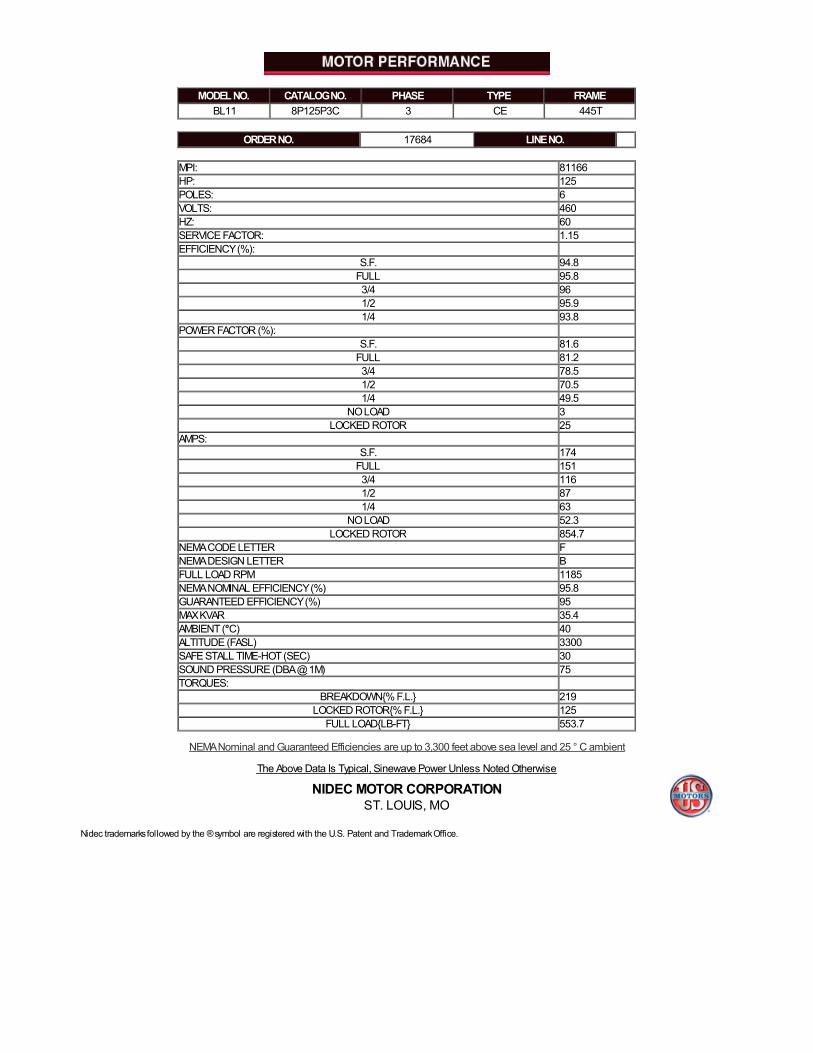
MODEL NO. CATALOG NO. PHASE TYPE FRAME BL11 8P125P3C 3 CE 445T
ORDER NO. 17684 LINE NO.
MPI: 81166HP: 125POLES: 6VOLTS: 460HZ: 60SERVICE FACTOR: 1.15EFFICIENCY (%):
S.F. 94.8FULL 95.83/4 961/2 95.91/4 93.8
POWER FACTOR (%): S.F. 81.6
FULL 81.23/4 78.51/2 70.51/4 49.5
NO LOAD 3LOCKED ROTOR 25
AMPS: S.F. 174
FULL 1513/4 1161/2 871/4 63
NO LOAD 52.3LOCKED ROTOR 854.7
NEMA CODE LETTER FNEMA DESIGN LETTER BFULL LOAD RPM 1185NEMA NOMINAL EFFICIENCY (%) 95.8GUARANTEED EFFICIENCY (%) 95MAX KVAR 35.4AMBIENT (°C) 40ALTITUDE (FASL) 3300SAFE STALL TIME-HOT (SEC) 30SOUND PRESSURE (DBA @ 1M) 75TORQUES:
BREAKDOWN{% F.L.} 219LOCKED ROTOR{% F.L.} 125
FULL LOAD{LB-FT} 553.7
NEMA Nominal and Guaranteed Efficiencies are up to 3,300 feet above sea level and 25 ° C ambient
The Above Data Is Typical, Sinewave Power Unless Noted Otherwise
NIDEC MOTOR CORPORATIONST. LOUIS, MO
Nidec trademarks followed by the ® symbol are registered with the U.S. Patent and Trademark Office.

EFFECTIVE: 2/27/96SUPERCEDES: X736618, 96441, 179879, 284138Connection Plate: 499495Connection Decal: 912113
499495
Motor Wiring Diagram
T1
T2T3 DELTAConnection
T1
T2T3 WYEConnection
or
LEAD CONNECTION
LineEach lead may consist of one or more cables having thesame lead number.
499495
1 2 3
To reverse direction of rotation interchange connections L1 and L2.
Each lead may be comprised of one or more cables.Each cable will be marked with the appropriate lead number.
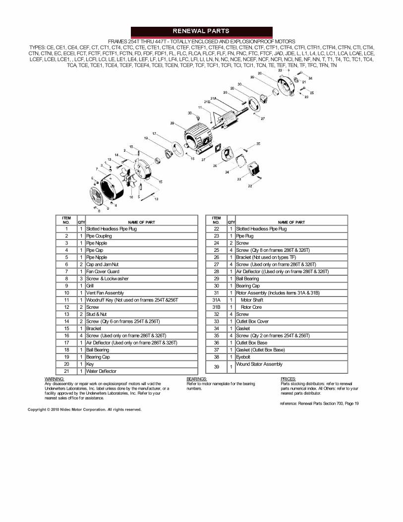
FRAMES 254T THRU 447T - TOTALLY ENCLOSED AND EXPLOSIONPROOF MOTORSTYPES: CE, CE1, CE4, CEF, CT, CT1, CT4, CTC, CTE, CTE1, CTE4, CTEF, CTEF1, CTEF4, CTEI, CTEN, CTF, CTF1, CTF4, CTFI, CTFI1, CTFI4, CTFN, CTI, CTI4,CTN, CTNI, EC, ECEI, FCT, FCTF, FCTF1, FCTN, FD, FDF, FDF1, FL, FLC, FLCA, FLCF, FLF, FN, FNC, FTC, FTCF, JAD, JDE, L, L1, L4, LC, LC1, LCA, LCAE, LCE,LCEF, LCEI, LCE1, , LCF, LCFI, LCI, LE, LE1, LE4, LEF, LF, LF1, LF4, LFC, LFI, LI, LN, N, NC, NCE, NCEF, NCF, NCFI, NCI, NE, NF, NN, T, T1, T4, TC, TC1, TC4,
TCA, TCE, TCE1, TCE4, TCEF, TCEF4, TCEI, TCEN, TCEP, TCF, TCF1, TCFI, TCI, TCI1, TCN, TE, TEF, TEN, TF, TFC, TFN, TN
ITEMNO. QTY NAME OF PART1 1 Slotted Headless Pipe Plug2 1 Pipe Coupling3 1 Pipe Nipple4 1 Pipe Cap5 1 Pipe Nipple6 2 Cap and Jam Nut7 1 Fan Cover Guard8 3 Screw & Lockwasher9 1 Grill10 1 Vent Fan Assembly11 1 Woodruff Key (Not used on frames 254T &256T12 2 Screw13 2 Stud & Nut14 2 Screw (Qty 6 on frames 254T & 256T)15 1 Bracket16 4 Screw (Used only on frame 286T & 326T)17 1 Air Deflector (Used only on frame 286T & 326T)18 1 Ball Bearing19 1 Bearing Cap20 1 Key21 1 Water Deflector
ITEMNO. QTY NAME OF PART22 1 Slotted Headless Pipe Plug23 1 Pipe Plug24 2 Screw25 4 Screw (Qty 8 on frames 286T & 326T)26 1 Bracket (Not used on types TF)27 4 Screw (Used only on frame 286T & 326T)28 1 Air Deflector ((Used only on frame 286T & 326T)29 1 Ball Bearing30 1 Bearing Cap31 1 Rotor Assembly (Includes items 31A & 31B)
31A 1 Motor Shaft31B 1 Rotor Core32 4 Screw33 1 Outlet Box Cover34 1 Gasket35 4 Screw (Qty 2 on frames 254T & 256T)36 1 Outlet Box Base37 1 Gasket (Outlet Box Base)38 1 Eyebolt
39 1 Wound Stator Assembly
WARNING:Any disassembly or repair work on explosionproof motors will void theUnderwriters Laboratories, Inc. label unless done by the manufacturer, or afacility approved by the Underwriters Laboratories, Inc. Refer to yournearest sales off ice for assistance.
BEARINGS:Refer to motor nameplate for the bearingnumbers.
PRICES:Parts stocking distributors: refer to renewalparts numerical index. All Others: refer to yournearest parts distributor.
reference: Renewal Parts Section 700, Page 19Copyright © 2010 Nidec Motor Corporation. All rights reserved.
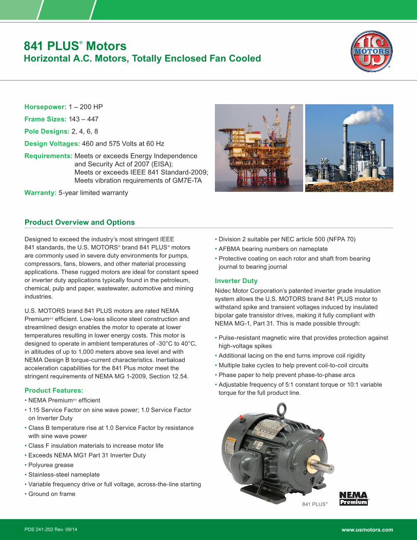
841 PLUS® MotorsHorizontal A.C. Motors, Totally Enclosed Fan Cooled
Designed to exceed the industry’s most stringent IEEE 841 standards, the U.S. MOTORS® brand 841 PLUS® motors are commonly used in severe duty environments for pumps, compressors, fans, blowers, and other material processing applications. These rugged motors are ideal for constant speed or inverter duty applications typically found in the petroleum, chemical, pulp and paper, wastewater, automotive and mining industries.
U.S. MOTORS brand 841 PLUS motors are rated NEMA Premium®† efficient. Low-loss silicone steel construction and streamlined design enables the motor to operate at lower temperatures resulting in lower energy costs. This motor is designed to operate in ambient temperatures of -30°C to 40°C, in altitudes of up to 1,000 meters above sea level and with NEMA Design B torque-current characteristics. Inertiaload acceleration capabilities for the 841 Plus motor meet the stringent requirements of NEMA MG 1-2009, Section 12.54.
Product Features:• NEMA Premium®† efficient• 1.15 Service Factor on sine wave power; 1.0 Service Factor
on Inverter Duty• Class B temperature rise at 1.0 Service Factor by resistance
with sine wave power• Class F insulation materials to increase motor life• Exceeds NEMA MG1 Part 31 Inverter Duty• Polyurea grease• Stainless-steel nameplate• Variable frequency drive or full voltage, across-the-line starting• Ground on frame
• Division 2 suitable per NEC article 500 (NFPA 70)• AFBMA bearing numbers on nameplate• Protective coating on each rotor and shaft from bearing
journal to bearing journal
Inverter DutyNidec Motor Corporation’s patented inverter grade insulation system allows the U.S. MOTORS brand 841 PLUS motor to withstand spike and transient voltages induced by insulated bipolar gate transistor drives, making it fully compliant with NEMA MG-1, Part 31. This is made possible through:
• Pulse-resistant magnetic wire that provides protection against high-voltage spikes
• Additional lacing on the end turns improve coil rigidity• Multiple bake cycles to help prevent coil-to-coil circuits• Phase paper to help prevent phase-to-phase arcs• Adjustable frequency of 5:1 constant torque or 10:1 variable
torque for the full product line.
Horsepower: 1 – 200 HP
Frame Sizes: 143 – 447
Pole Designs: 2, 4, 6, 8
Design Voltages: 460 and 575 Volts at 60 Hz
Requirements: Meets or exceeds Energy Independence and Security Act of 2007 (EISA); Meets or exceeds IEEE 841 Standard-2009; Meets vibration requirements of GM7E-TA
Warranty: 5-year limited warranty
Product Overview and Options
841 PLUS®
www.usmotors.comPDS 241-202 Rev. 09/14
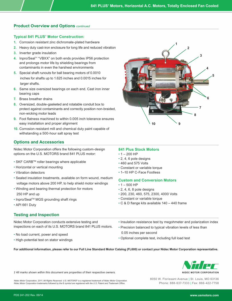
841 PLUS® Motors, Horizontal A.C. Motors, Totally Enclosed Fan Cooled
Typical 841 PLUS® Motor Construction:1. Corrosion resistant zinc dichromate-plated hardware 2. Heavy duty cast-iron enclosure for long life and reduced vibration3. Inverter grade insulation4. Inpro/SealTM “VBXX” on both ends provides IP56 protection
and prolongs motor life by shielding bearings from contaminants in even the harshest environments
5. Special shaft runouts for ball bearing motors of 0.0010 inches for shafts up to 1.625 inches and 0.0015 inches for larger shafts.6. Same size oversized bearings on each end. Cast iron inner
bearing caps7. Brass breather drains8. Oversized, double-gasketed and rotatable conduit box to
protect against contaminants and correctly position non-braided, non-wicking motor leads
9. Foot flatness machined to within 0.005 inch tolerance ensures easy installation and proper alignment
10. Corrosion-resistant mill and chemical duty paint capable of withstanding a 500-hour salt spray test
Product Overview and Options continued
Nidec Motor Corporation offers the following custom-design options on the U.S. MOTORS brand 841 PLUS motor:
• SKF CARBTM roller bearings where applicable• Horizontal or vertical mounting• Vibration detectors• Sealed insulation treatments, available on form wound, medium voltage motors above 200 HP, to help shield motor windings• Winding and bearing thermal protection for motors 250 HP and up• Inpro/SealTM MGS grounding shaft rings• API 661 Duty
841 Plus Stock Motors• 1 – 200 HP• 2, 4, 6 pole designs• 460 and 575 Volts• Constant or variable torque• 1–10 HP C-Face Footless
Custom and Conversion Motors• 1 – 500 HP• 2, 4, 6, 8 pole designs• 200, 230, 460, 575, 2300, 4000 Volts• Constant or variable torque• C & D flange kits available 140 – 440 frame
Options and Accessories
Nidec Motor Corporation conducts extensive testing and inspections on each of its U.S. MOTORS brand 841 PLUS motors.
• No load current, power and speed• High-potential test on stator windings
• Insulation resistance test by megohmeter and polarization index• Precision balanced to typical vibration levels of less than 0.05 inches per second• Optional complete test, including full load test
Testing and Inspection
For additional information, please refer to our Full Line Standard Motor Catalog (FL600) or contact your Nidec Motor Corporation representative.
12
4
7
8
910
3
5
6
8050 W. Florissant Avenue | St. Louis, MO 63136Phone: 888-637-7333 | Fax: 866-422-7758
† All marks shown within this document are properties of their respective owners.
Nidec Motor Corporation, 2011; All Rights Reserved. U.S. MOTORS® is a registered trademark of Nidec Motor Corporation. Nidec Motor Corporation trademarks followed by the ® symbol are registered with the U.S. Patent and Trademark Office.
www.usmotors.comPDS 241-202 Rev. 09/14
† All marks shown within this document are properties of their respective owners.
Variable Frequency Drives (VFD)All Nidec Motor Corporation inverter duty motors have 40°C ambient, 1.0 SF on Inverter Power, 3300 ft. max altitude, 460 voltage or less line power, up to 10:1 speed range on Variable Torque and Class F Insulation. Nidec Motor Corporation’s INVERTER GRADE® insulated motors exceeded NEMA®† MG-1 Part 30 & 31 before the standards were established.We are a leader in the development of electric motors to withstand pulse width modulated (PWM) drives evolution from power transistors to higher switching frequency insulated gate bipolar transistors (IGBTs).Today, as the need for medium duty motor inverter applications grows, Nidec Motor Corporation provides products to meet these demands.Through continued research and development, Nidec Motor Corporation has included the insulation wire from its INVERTER GRADE® motors in all Premium Efficient motors, enhancing their potential inverter compatibility.Inverter compatibility with motors is complex. As a result, many variables must be considered when determining the suitability of certain types of motors. These variables include: • Torque requirements (Constant or Variable) • Speed Range • Line/System Voltage • Cable Length between VFD & Motor • Drive Switching (Carrier) Frequency Motor Construction • VFD dv/dt • High Temperatures High HumidityWider speed ranges, higher voltages, higher switching frequencies and increased cable lengths all add to the severity of the application and therefore the potential for premature motor failure. Nidec Motor Corporation has differentiated its products into families for your ease of selection for various inverter applications.
Warranty GuidelinesThe information within this section refers to the motor and drive application guidelines and limitations for warranty.
Hazardous Location MotorsUse of a variable frequency drive with the motors in this catalog, intended for use in hazardous locations, is only approved for Division 1, Class I, Group D hazardous location motors with a T2B temperature code, with a limitation of 2:1 constant torque or 10:1 variable torque output. No other stock hazardous location motors are inherently suitable for operation with a variable frequency drive. If other requirements are needed, including non-listed Division 2, please contact your Nidec Motor Corporation territory manager to conduct an engineering inquiry.
575 Volt Motors575 volt motors can be applied on inverters when output filters are used.
Applying INVERTER GRADE® Insulated Motors onVariable Frequency Drives (2, 4, 6 pole)The products within this catalog labeled “Inverter Duty” or “Vector Duty” are considered INVERTER GRADE® insulated motors. INVERTER GRADE® motors exceed the NEMA®† MG-1 Part 31 standard.Nidec Motor Corporation provides a three-year limited warranty on all NEMA®† frame INVERTER GRADE® insulated motors and allows long cable runs between the motor and the VFD (limited to 400 feet typical without output filters). Cable distance can be further limited by hot and humid environments and VFD manufacturers cable limits. These motors may be appropriate for certain severe inverter application or when the factors relating to the end use application are undefined (such as spares). Nidec Motor Corporation’s U.S. Motors® brand is available in the following INVERTER GRADE® insulated motors: • Inverter Duty NEMA®† frame motors good for 10:1 Variable Torque & 5:1 Constant Torque, including Vertical Type RUSI • Inverter Duty motors rated for 10:1 Constant Torque • ACCU-Torq® and Vector Duty Motors with full torque to 0 Speed • 841 Plus® NEMA®† Frame Motors
Applying motors that do not have INVERTER GRADE® insulation on Variable Frequency Drives (2, 4, 6 pole)Meet NEMA®† MG-1, Section IV, Part 31.4.4.2. They can be used with adjustable frequency drives under the following parameters: On NEMA®† frame motors, 10:1 speed rating on variable torque loads & 4:1 speed range on constant torque loads. On TITAN® frame motors, 10:1 speed rating on variable torque loads. On TITAN® frame motors, inquiry required for suitability on constant torque loads. Cable distances are for reference only and can be further limited by hot and humid environments. Refer to specific VFD manufacturers cable limits.
Applying Standard & Energy Efficient Motors on Variable Frequency Drives is not recommended. VFD related failures on standard and energy efficient motors 444 frame and above will not be covered under warranty.
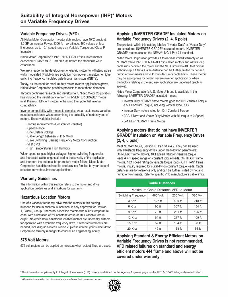
Cable Distances
Maximum Cable Distance VFD to MotorSwitching Frequency 460 Volt 230 Volt 380 Volt
3 Khz 127 ft 400 ft 218 ft
6 Khz 90 ft 307 ft 154 ft
9 Khz 73 ft 251 ft 126 ft
12 Khz 64 ft 217 ft 109 ft
15 Khz 57 ft 194 ft 98 ft
20 Khz 49 ft 168 ft 85 ft
*This information applies only to Integral Horsepower (IHP) motors as defined on the Agency Approval page, under UL®† & CSA®† listings where indicated.
Suitability of Integral Horsepower (IHP)* Motorson Variable Frequency Drives
† All marks shown within this document are properties of their respective owners.
Thermal Overloads and Single Phase MotorsMotors with thermal overloads installed may not operate properly on a VFD. The current carrying thermal overload is designed for sine wave power. Operation on a VFD may cause nuisance tripping or potentially not protect the motor as would be expected on line power. Thermo-stats or thermistors installed in the motor and connected properly to the VFD may provide suitable thermal overload protection when operating on a VFD. (Consult Codes)
Single phase motors and other fractional horsepower ratings are not designed to be operated on a VFD. Within Nidec Motor Corporation standard products, all motors NEMA®† 48 frame (5.5” diameter) and smaller are not suitable for VFD applications. Three phase 56 and 143/145 frame applications should be noted on the catalog price page; or if in doubt ask an Nidec Motor Corporation technical representative for recommendations on compatibility with a VFD.
Slow Speed MotorsMotors with a base design of slower than six poles require special consideration regarding VFD sizing and minimizing harmonic distortion created at the motor terminals due to cable installation characteristics. Additional external PWM waveform filters and shielded motor cables designed for PWM power may be required to provide acceptable motor life. Harmonic distortion on the output waveform should be kept to a minimum level (less than 10%).
690V Applications Motors that will be applied to 690VAC PWM VFDs require the use of an external filter to limit peak voltage spikes and the use of an INVERTER GRADE® motor. Where available, an alternative to using an output filter is to upgrade to a 2300V insulation system.
Low Voltage TITAN® MotorsWhen using 449 frame and larger motors on PWM type VFDs consider the use of an external filter and shielded motor cables designed for PWM power to minimize harmonic distortion and peak voltages at the motor terminals. Harmonic distortion on the output waveform should be kept to a minimum level (less than 10%).
Bearing Currents related to PWM waveformDue to the uniqueness of this condition occurring in the field, protection of the motor bearings from shaft currents caused by common mode voltages is not a standard feature on sine wave or Inverter Duty motor products, unless explicitly noted. Some installations may be prone to a voltage discharge condition through the motor bearings called fluting.
Fluting damage is related to characteristics of the PWM waveform, VFD programming and characteristics and installation.
Bearing fluting as a result of VFD waveform characteristics may be prevented by the installation of a shaft grounding device such as a brush or ring and/or correction of the installation characteristics causing the shaft voltage condition. Insulated bearing(s) may be required. VFD filters may be needed if bearing fluting is to be avoided.
Multiple Motors on a Single VFD Special considerations are required when multiple motors are powered from a single VFD unit. Most VFD manufacturers can provide guidelines for proper motor thermal considerations and starting/stopping of motors. Cable runs from the VFD and each motor can create conditions that will cause extra stress on the motor winding. Filters may be required at the motor to provide maximum motor life.
Grounding and Cable Installation Guidelines Proper output winding and grounding practices can be instrumental in minimizing motor related failures caused by PWM waveform characteristics and installation factors. VFD manufacturers typically provide detailed guidelines on the proper grounding of the motor to the VFD and output cable routing. Cabling manufacturers provide recommended cable types for PWM installations and critical information concerning output wiring impedance and capacitance to ground.
Vertical Motors on VFDs Vertical motors operated on VFD power present unique conditions that may require consideration by the user or installation engineer:
• Non-reversing-ratchet operation can interfere at low speeds (up to 300 RPM) causing locked rotor and drive tripping.
• Unexpected / unacceptable system vibration and or noise levels caused by the torque pulsation characteristics of the PWM waveform, a system critical frequency falling inside the variable speed range of the process or the added harmonic content of the PWM waveform exciting a system component
• Application related problems related to the controlled acceleration/deceleration and torque of the motor on VFD power and the building of system pressure/ load.
• The impact the reduction of pump speed has on the down thrust reflected to the pump motor and any minimum thrust requirements of the motor bearings
• Water hammer during shutdown damaging the non-reversing ratchet
Humidity and Non-operational Conditions The possible build-up of condensation inside the motor due to storage in an uncontrolled environment or non-operational periods in an installation, can lead to an increased rate of premature winding or bearing failures when combined with the stresses associated with PWM waveform characteristics. Moisture and condensation in and on the motor winding over time can provide tracking paths to ground, lower the Megohm resistance of the motor winding to ground, and lower the Corona Inception Voltage level of the winding.
Proper storage and maintenance guidelines are important to minimize the potential of premature failures. Space heaters or trickle voltage heating methods are the preferred methods for drying out a winding that has low megaohm readings. Damage caused by these factors are not covered by the limited warranty provided unless appropriate heating methods are properly utilized during non-operational periods and prior to motor start-up.
NEMA®† Application Guide for AC Adjustable Speed Drive Systems: http://www.nema.org/stds/acadjustable.cfm#download
*This information applies only to Integral Horsepower (IHP) motors as defined on the Agency Approval page, under UL®† & CSA®† listings where indicated.
Motor / InverterCompatibility