Embed Size (px)
Citation preview
Motion ControlNI PCI-7342 Hardware User Manual
NI PCI-7342 Hardware User Manual
October 2002 EditionPart Number 373454A-01
Support
Worldwide Technical Support and Product Information
ni.com
National Instruments Corporate Headquarters
11500 North Mopac Expressway Austin, Texas 78759-3504 USA Tel: 512 683 0100
Worldwide Offices
Australia 03 9879 5166, Austria 0662 45 79 90 0, Belgium 02 757 00 20, Brazil 55 11 3262 3599, Canada (Calgary) 403 274 9391, Canada (Montreal) 514 288 5722, Canada (Ottawa) 613 233 5949, Canada (Québec) 514 694 8521, Canada (Toronto) 905 785 0085, China 86 21 6555 7838, Czech Republic 02 2423 5774, Denmark 45 76 26 00, Finland 09 725 725 11, France 01 48 14 24 24, Germany 089 741 31 30, Greece 01 42 96 427, Hong Kong 2645 3186, India 91 80 4190000, Israel 03 6393737, Italy 02 413091, Japan 03 5472 2970, Korea 02 3451 3400, Malaysia 603 9596711, Mexico 001 800 010 0793, Netherlands 0348 433466, New Zealand 09 914 0488, Norway 32 27 73 00, Poland 22 3390 150, Portugal 210 311 210, Russia 095 238 7139, Singapore 65 6 226 5886, Slovenia 3 425 4200, South Africa 11 805 8197, Spain 91 640 0085, Sweden 08 587 895 00, Switzerland 056 200 51 51, Taiwan 02 2528 7227, United Kingdom 01635 523545
For further support information, refer to the Technical Support and Professional Services appendix. To comment on the documentation, send email to [email protected].
© 2002 National Instruments Corporation. All rights reserved.
Important Information
WarrantyThe NI PCI-7342 controller is warranted against defects in materials and workmanship for a period of one year from the date of shipment, as evidenced by receipts or other documentation. National Instruments will, at its option, repair or replace equipment that proves to be defective during the warranty period. This warranty includes parts and labor.
The media on which you receive National Instruments software are warranted not to fail to execute programming instructions, due to defects in materials and workmanship, for a period of 90 days from date of shipment, as evidenced by receipts or other documentation. National Instruments will, at its option, repair or replace software media that do not execute programming instructions if National Instruments receives notice of such defects during the warranty period. National Instruments does not warrant that the operation of the software shall be uninterrupted or error free.
A Return Material Authorization (RMA) number must be obtained from the factory and clearly marked on the outside of the package before any equipment will be accepted for warranty work. National Instruments will pay the shipping costs of returning to the owner parts which are covered by warranty.
National Instruments believes that the information in this document is accurate. The document has been carefully reviewed for technical accuracy. In the event that technical or typographical errors exist, National Instruments reserves the right to make changes to subsequent editions of this document without prior notice to holders of this edition. The reader should consult National Instruments if errors are suspected. In no event shall National Instruments be liable for any damages arising out of or related to this document or the information contained in it.
EXCEPT AS SPECIFIED HEREIN, NATIONAL INSTRUMENTS MAKES NO WARRANTIES, EXPRESS OR IMPLIED, AND SPECIFICALLY DISCLAIMS ANY WARRANTY OF MERCHANTABILITY OR FITNESS FOR A PARTICULAR PURPOSE. CUSTOMER’S RIGHT TO RECOVER DAMAGES CAUSED BY FAULT OR NEGLIGENCE ON THE PART OF NATIONAL INSTRUMENTS SHALL BE LIMITED TO THE AMOUNT THERETOFORE PAID BY THE CUSTOMER. NATIONAL INSTRUMENTS WILL NOT BE LIABLE FOR DAMAGES RESULTING FROM LOSS OF DATA, PROFITS, USE OF PRODUCTS, OR INCIDENTAL OR CONSEQUENTIAL DAMAGES, EVEN IF ADVISED OF THE POSSIBILITY THEREOF. This limitation of the liability of National Instruments will apply regardless of the form of action, whether in contract or tort, including negligence. Any action against National Instruments must be brought within one year after the cause of action accrues. National Instruments shall not be liable for any delay in performance due to causes beyond its reasonable control. The warranty provided herein does not cover damages, defects, malfunctions, or service failures caused by owner’s failure to follow the National Instruments installation, operation, or maintenance instructions; owner’s modification of the product; owner’s abuse, misuse, or negligent acts; and power failure or surges, fire, flood, accident, actions of third parties, or other events outside reasonable control.
CopyrightUnder the copyright laws, this publication may not be reproduced or transmitted in any form, electronic or mechanical, including photocopying, recording, storing in an information retrieval system, or translating, in whole or in part, without the prior written consent of National Instruments Corporation.
TrademarksCVI™, LabVIEW™, National Instruments™, NI™, ni.com™, NI-Motion™, and RTSI™ are trademarks of National Instruments Corporation.
Product and company names mentioned herein are trademarks or trade names of their respective companies.
WARNING REGARDING USE OF NATIONAL INSTRUMENTS PRODUCTS(1) NATIONAL INSTRUMENTS PRODUCTS ARE NOT DESIGNED WITH COMPONENTS AND TESTING FOR A LEVEL OF RELIABILITY SUITABLE FOR USE IN OR IN CONNECTION WITH SURGICAL IMPLANTS OR AS CRITICAL COMPONENTS IN ANY LIFE SUPPORT SYSTEMS WHOSE FAILURE TO PERFORM CAN REASONABLY BE EXPECTED TO CAUSE SIGNIFICANT INJURY TO A HUMAN.
(2) IN ANY APPLICATION, INCLUDING THE ABOVE, RELIABILITY OF OPERATION OF THE SOFTWARE PRODUCTS CAN BE IMPAIRED BY ADVERSE FACTORS, INCLUDING BUT NOT LIMITED TO FLUCTUATIONS IN ELECTRICAL POWER SUPPLY, COMPUTER HARDWARE MALFUNCTIONS, COMPUTER OPERATING SYSTEM SOFTWARE FITNESS, FITNESS OF COMPILERS AND DEVELOPMENT SOFTWARE USED TO DEVELOP AN APPLICATION, INSTALLATION ERRORS, SOFTWARE AND HARDWARE COMPATIBILITY PROBLEMS, MALFUNCTIONS OR FAILURES OF ELECTRONIC MONITORING OR CONTROL DEVICES, TRANSIENT FAILURES OF ELECTRONIC SYSTEMS (HARDWARE AND/OR SOFTWARE), UNANTICIPATED USES OR MISUSES, OR ERRORS ON THE PART OF THE USER OR APPLICATIONS DESIGNER (ADVERSE FACTORS SUCH AS THESE ARE HEREAFTER COLLECTIVELY TERMED “SYSTEM FAILURES”). ANY APPLICATION WHERE A SYSTEM FAILURE WOULD CREATE A RISK OF HARM TO PROPERTY OR PERSONS (INCLUDING THE RISK OF BODILY INJURY AND DEATH) SHOULD NOT BE RELIANT SOLELY UPON ONE FORM OF ELECTRONIC SYSTEM DUE TO THE RISK OF SYSTEM FAILURE. TO AVOID DAMAGE, INJURY, OR DEATH, THE USER OR APPLICATION DESIGNER MUST TAKE REASONABLY PRUDENT STEPS TO PROTECT AGAINST SYSTEM FAILURES, INCLUDING BUT NOT LIMITED TO BACK-UP OR SHUT DOWN MECHANISMS. BECAUSE EACH END-USER SYSTEM IS CUSTOMIZED AND DIFFERS FROM NATIONAL INSTRUMENTS' TESTING PLATFORMS AND BECAUSE A USER OR APPLICATION DESIGNER MAY USE NATIONAL INSTRUMENTS PRODUCTS IN COMBINATION WITH OTHER PRODUCTS IN A MANNER NOT EVALUATED OR CONTEMPLATED BY NATIONAL INSTRUMENTS, THE USER OR APPLICATION DESIGNER IS ULTIMATELY RESPONSIBLE FOR VERIFYING AND VALIDATING THE SUITABILITY OF NATIONAL INSTRUMENTS PRODUCTS WHENEVER NATIONAL INSTRUMENTS PRODUCTS ARE INCORPORATED IN A SYSTEM OR APPLICATION, INCLUDING, WITHOUT LIMITATION, THE APPROPRIATE DESIGN, PROCESS AND SAFETY LEVEL OF SUCH SYSTEM OR APPLICATION.

Compliance
FCC/Canada Radio Frequency Interference Compliance
Determining FCC ClassThe Federal Communications Commission (FCC) has rules to protect wireless communications from interference. The FCC places digital electronics into two classes. These classes are known as Class A (for use in industrial-commercial locations only) or Class B (for use in residential or commercial locations). Depending on where it is operated, this product could be subject to restrictions in the FCC rules. (In Canada, the Department of Communications (DOC), of Industry Canada, regulates wireless interference in much the same way.)Digital electronics emit weak signals during normal operation that can affect radio, television, or other wireless products. By examining the product you purchased, you can determine the FCC Class and therefore which of the two FCC/DOC Warnings apply in the following sections. (Some products may not be labeled at all for FCC; if so, the reader should then assume these are Class A devices.)FCC Class A products only display a simple warning statement of one paragraph in length regarding interference and undesired operation. Most of our products are FCC Class A. The FCC rules have restrictions regarding the locations where FCC Class A products can be operated.FCC Class B products display either a FCC ID code, starting with the letters EXN, or the FCC Class B compliance mark that appears as shown here on the right.Consult the FCC Web site at http://www.fcc.gov for more information.
FCC/DOC WarningsThis equipment generates and uses radio frequency energy and, if not installed and used in strict accordance with the instructions in this manual and the CE Marking Declaration of Conformity*, may cause interference to radio and television reception. Classification requirements are the same for the Federal Communications Commission (FCC) and the Canadian Department of Communications (DOC). Changes or modifications not expressly approved by National Instruments could void the user’s authority to operate the equipment under the FCC Rules.
Class AFederal Communications CommissionThis equipment has been tested and found to comply with the limits for a Class A digital device, pursuant to part 15 of the FCC Rules. These limits are designed to provide reasonable protection against harmful interference when the equipment is operated in a commercial environment. This equipment generates, uses, and can radiate radio frequency energy and, if not installed and used in accordance with the instruction manual, may cause harmful interference to radio communications. Operation of this equipment in a residential area is likely to cause harmful interference in which case the user will be required to correct the interference at his own expense.
Canadian Department of CommunicationsThis Class A digital apparatus meets all requirements of the Canadian Interference-Causing Equipment Regulations.Cet appareil numérique de la classe A respecte toutes les exigences du Règlement sur le matériel brouilleur du Canada.
Class BFederal Communications CommissionThis equipment has been tested and found to comply with the limits for a Class B digital device, pursuant to part 15 of the FCC Rules. These limits are designed to provide reasonable protection against harmful interference in a residential installation. This equipment generates, uses, and can radiate radio frequency energy and, if not installed and used in accordance with the instructions, may cause harmful interference to radio communications. However, there is no guarantee that interference will not occur in a particular installation. If this equipment does cause harmful interference to radio or television reception, which can be determined by turning the equipment off and on, the user is encouraged to try to correct the interference by one or more of the following measures:• Reorient or relocate the receiving antenna.• Increase the separation between the equipment and receiver.• Connect the equipment into an outlet on a circuit different from that to which the receiver is connected.• Consult the dealer or an experienced radio/TV technician for help.
Canadian Department of CommunicationsThis Class B digital apparatus meets all requirements of the Canadian Interference-Causing Equipment Regulations.Cet appareil numérique de la classe B respecte toutes les exigences du Règlement sur le matériel brouilleur du Canada.
Compliance to EU DirectivesReaders in the European Union (EU) must refer to the Manufacturer’s Declaration of Conformity (DoC) for information* pertaining to the CE Marking compliance scheme. The Manufacturer includes a DoC for most every hardware product except for those bought for OEMs, if also available from an original manufacturer that also markets in the EU, or where compliance is not required as for electrically benign apparatus or cables.To obtain the DoC for this product, click Declaration of Conformity at ni.com/hardref.nsf/. This Web site lists the DoCs by product family. Select the appropriate product family, followed by your product, and a link to the DoC appears in Adobe Acrobat format. Click the Acrobat icon to download or read the DoC.
* The CE Marking Declaration of Conformity will contain important supplementary information and instructions for the user or installer.
© National Instruments Corporation vii NI PCI-7342 Hardware User Manual
Contents
About This ManualConventions ................................................................................................................... ixRelated Documentation..................................................................................................x
Chapter 1Introduction
About the NI PCI-7342..................................................................................................1-1Hardware .........................................................................................................1-1RTSI ................................................................................................................1-1PCI-7342 Features ...........................................................................................1-2Servo and Stepper Fundamentals ....................................................................1-2
Getting Started ...............................................................................................................1-3Software Programming Choices ....................................................................................1-3National Instruments Application Software ..................................................................1-3Optional Equipment .......................................................................................................1-4Motion I/O Connections ................................................................................................1-4
Chapter 2Configuration and Installation
Software Installation ......................................................................................................2-1Controller Configuration................................................................................................2-1Unpacking ......................................................................................................................2-1Safety Information .........................................................................................................2-2Hardware Installation.....................................................................................................2-4
Chapter 3Hardware Overview
User Connectors.............................................................................................................3-2
Chapter 4Functional Overview
Dual Processor Architecture ..........................................................................................4-1Embedded Real-Time Operating System (RTOS) ..........................................4-2Trajectory Generators......................................................................................4-2Analog Feedback .............................................................................................4-2Flash Memory..................................................................................................4-3
Contents
NI PCI-7342 Hardware User Manual viii ni.com
Axes and Motion Resources.......................................................................................... 4-3Axes ................................................................................................................ 4-3Motion Resources ........................................................................................... 4-4
Host Communications ................................................................................................... 4-5
Chapter 5Signal Connections
Motion I/O Connector ................................................................................................... 5-2Motion Axis Signals........................................................................................ 5-5Limit and Home Inputs ................................................................................... 5-6
Wiring Concerns............................................................................... 5-7Limit and Home Input Circuit .......................................................... 5-7
Encoder Signals............................................................................................... 5-8Encoder <1..2> Phase A/Phase B ..................................................... 5-8Encoder <1..2> Index ....................................................................... 5-9Wiring Concerns............................................................................... 5-10Encoder Input Circuit ....................................................................... 5-11Trigger Inputs, Shutdown Input, and Breakpoint Outputs ............... 5-11Wiring Concerns............................................................................... 5-12Trigger Input, Shutdown Input, and Breakpoint Output Circuits..... 5-12
Analog Inputs .................................................................................................. 5-13Wiring Concerns............................................................................... 5-15
Other Motion I/O Connection ......................................................................... 5-15Digital I/O Connector .................................................................................................... 5-16
PWM Features................................................................................................. 5-17RTSI Connector............................................................................................................. 5-17
RTSI Signal Considerations............................................................................ 5-17
Appendix ASpecifications
Appendix BCable Connector Descriptions
Appendix CTechnical Support and Professional Services
Glossary
Index
© National Instruments Corporation ix NI PCI-7342 Hardware User Manual
About This Manual
This manual provides guidelines for programming and operating the National Instruments PCI-7342 motion controller and includes controller specifications and descriptions of electrical and mechanical features.
Refer to the Glossary for definitions of selected related terms.
ConventionsThe manual uses the following conventions:
<> Angle brackets that contain numbers separated by an ellipsis represent a range of values associated with a bit or signal name—for example, DBIO<3..0>.
This icon denotes a note, which alerts you to important information.
This icon denotes a caution, which advises you of precautions to take to avoid injury, data loss, or a system crash.
bold Bold text denotes items that you must select or click in the software, such as menu items and dialog box options. Bold text also denotes parameter names.
italic Italic text denotes variables, emphasis, a cross reference, or an introduction to a key concept. This font also denotes text that is a placeholder for a word or value that you must supply.
monospace Text in this font denotes text or characters that you should enter from the keyboard, sections of code, programming examples, and syntax examples. This font is also used for the proper names of disk drives, paths, directories, programs, subprograms, subroutines, device names, functions, operations, variables, filenames and extensions, and code excerpts.
About This Manual
NI PCI-7342 Hardware User Manual x ni.com
Related DocumentationThe following documents contain information pertaining to the PCI-7342 motion controller:
• NI-Motion Release Notes
• NI-Motion Software Reference Manual
• NI-Motion Software Reference online help
• NI-Motion VIs online help
• PCI Local Bus Specification, Revision 2.1
• Your computer’s technical reference manual
© National Instruments Corporation 1-1 NI PCI-7342 Hardware User Manual
1Introduction
This chapter describes the features and functionality of the National Instruments PCI-7342 motion controller. It includes a list of items necessary for getting started with your controller, software choices, and optional equipment.
About the NI PCI-7342The NI PCI-7342 motion controller features advanced motion control with easy-to-use software tools and add-on motion VI libraries for use with LabVIEW. The PCI-7342 controller provides dedicated motion I/O for limit and home switches and additional I/O for general-purpose functions.
The following sections describe the features of the PCI-7342.
HardwareThe PCI-7342 controller has high-performance capabilities because of the advanced dual-processor architecture that uses a Motorola MC68331 real-time 32-bit CPU, combined with an Analog Devices ADSP-2185 digital signal processor (DSP) and custom field programmable gate arrays (FPGAs). The first-in-first-out (FIFO) bus interface and powerful function set provide high-speed communications while offloading complex motion functions from the host PC for optimum command throughput and system performance.
Each axis has motion I/O for end-of-travel limit and home switch inputs, breakpoint output, trigger input, and encoder feedback rates up to 20 MHz. The PCI-7342 controller also has nondedicated user I/O, including 32 bits of digital I/O and two analog inputs for ±10 V signals, joystick inputs, or monitoring of analog sensors. Additionally, the analog inputs can provide feedback for loop closure.
RTSIThe PCI-7342 controller supports the National Instruments Real-Time System Integration (RTSI) bus. RTSI is a dedicated, high-speed digital bus that facilitates low-level, high-speed, real-time communication between
Chapter 1 Introduction
NI PCI-7342 Hardware User Manual 1-2 ni.com
National Instruments devices. The RTSI bus provides high-speed connectivity between National Instruments products, including image acquisition (IMAQ) and data acquisition (DAQ) devices. With RTSI, you can easily synchronize several functions to a common trigger or timing event across multiple motion, IMAQ, and DAQ devices.
RTSI requires no external cabling and does not consume host bus bandwidth. Additionally, the RTSI bus features built-in switching that you can control with software to route signals to and from the bus on the fly.
The bus interface on PCI devices is an internal 34-pin connector. Signals are shared through a ribbon cable inside the PC enclosure. RTSI cables are available for chaining two, three, four, or five devices together.
Note Seven of the 34 pins on the RTSI connector are available for user signals. You can use the software-configurable RTSI switch to accommodate more than seven signal options for each device. With this many-to-few selector switch, any available signal can be routed to any RTSI pin. You can also route more than one signal to a single RTSI pin or connect two RTSI pins to the same signal.
Refer to the National Instruments Developer Zone at ni.com/zone for more information about RTSI, including tutorials, examples, and configuration guidelines.
PCI-7342 FeaturesThe PCI-7342 controller combines servo and stepper functionality for PCI bus computers. It provides motion control for up to two independent or coordinated axes of motion.
You can use the PCI-7342 motion controller for point-to-point and straight-line vector moves for stepper and servo motor applications.
Servo and Stepper FundamentalsServo axes can control servo motors, servo hydraulics, servo valves, and other servo devices. Servo axes always operate in closed-loop mode. These axes use quadrature encoders or analog inputs for position and velocity feedback and provide analog command outputs with an industry-standard range of ±10 V.
Stepper axes control stepper motors and operate in open- or closed-loop mode. They use quadrature encoders or analog inputs for position and velocity feedback (closed-loop only), and provide step/direction or
Chapter 1 Introduction
© National Instruments Corporation 1-3 NI PCI-7342 Hardware User Manual
clockwise (CW) /counter-clockwise (CCW) digital command outputs. All stepper axes support full, half, and microstepping applications.
Getting StartedThe following items are necessary for setting up and getting started with your motion controller:
PCI-7342 motion controller
A computer with an available PCI slot
One of the following software packages and documentation:
– LabVIEW
– LabWindows™/CVI™
– NI-Motion
NI PCI-7342 Hardware User Manual
NI-Motion Software Reference Manual
Software Programming ChoicesThe simple but powerful high-level function set application programming interface (API) makes programming your controller easy. All setup and motion control functions are easily executed by calling into either a static or dynamic link library (DLL). These libraries are callable from C, Visual Basic, and other high-level languages. Full function set implementations are available for LabVIEW, LabWindows/CVI, and other industry-standard software programs.
National Instruments Application SoftwareLabVIEW is based on the graphical programming language G and features interactive graphics and a state-of-the-art user interface. In LabVIEW, you can create 32-bit compiled programs and stand-alone executables for custom automation, data acquisition, test, measurement, and control solutions. National Instruments offers the NI-Motion VI Library, a series of virtual instruments (VIs) for using LabVIEW with the National Instruments motion control hardware. The NI-Motion VI library implements the full function set API and a powerful set of demo functions, example programs, and fully operational, high-level application routines.
Chapter 1 Introduction
NI PCI-7342 Hardware User Manual 1-4 ni.com
ANSI C-based LabWindows/CVI also features interactive graphics and a state-of-the-art user interface. Using LabWindows/CVI, you can generate C code for custom data acquisition, test, and all measurement and automation solutions.
NI-Motion is the motion control software and virtual instruments (VIs) for interfacing with all National Instruments motion controllers.
Optional EquipmentThe following optional products are available for use with the National Instruments motion controllers:
• Cables and cable assemblies for motion and digital I/O
• RTSI bus cables
• UMI wiring connectivity blocks with integrated motion signal conditioning and motion inhibit functionality
• Stepper and servo motor compatible driver amplifier units with integrated power supply and wiring connectivity
• Connector blocks, shielded and unshielded 68-pin screw terminal wiring aids
For specific information about these products, refer to the National Instruments catalog, the National Instruments Web site at ni.com, or call your National Instruments sales representative.
Motion I/O ConnectionsThe external motion I/O and digital I/O connectors are high-density, 68-pin female VHDCI connectors. Refer to the User Connectors section of Chapter 3, Hardware Overview, for more information about these connectors.
For custom cables, use the AMP mating connector (part number 787801-01).
© National Instruments Corporation 2-1 NI PCI-7342 Hardware User Manual
2Configuration and Installation
This chapter describes how to configure, unpack, and install the National Instruments PCI-7342 motion controller.
Software InstallationBefore installing your controller, install the NI-Motion driver software and, if appropriate, the Motion VI libraries.
Note You must install the NI-Motion driver software before installing your motion controller.
Refer to the Release Notes included with the controller for specific instructions on the software installation sequence for your host PC.
Controller ConfigurationBecause motion I/O-related configuration is performed entirely with software, it is not necessary to set jumpers for motion I/O configuration.
The PCI-7342 controller is fully compatible with the PCI Local Bus Specification, Revision 2.1. It is not necessary to configure jumpers for bus-related configuration.
UnpackingThe PCI-7342 motion controller ships in an antistatic package to prevent electrostatic discharge from damaging board components. To avoid such damage in handling the controller, take the following precautions:
1. Ground yourself via a grounding strap or by holding a grounded object, such as your computer chassis.
2. Touch the antistatic package to a metal part of your computer chassis before removing the controller from the package.
3. Remove the controller from the package and inspect it for loose components or any other signs of damage. Notify National Instruments
Chapter 2 Configuration and Installation
NI PCI-7342 Hardware User Manual 2-2 ni.com
if the controller appears damaged in any way. Do not install a damaged controller in your computer.
Caution Never touch the exposed connector pins.
Safety Information
Caution The following paragraphs contain important safety information you must follow when installing and operating the device.
Do not operate the device in a manner not specified in the documentation. Misuse of the device may result in a hazard and may compromise the safety protection built into the device. If the device is damaged, turn it off and do not use it until service-trained personnel can check its safety. If necessary, return the device to National Instruments for repair.
Keep away from live circuits. Do not remove equipment covers or shields unless you are trained to do so. If signal wires are connected to the device, hazardous voltages can exist even when the equipment is turned off. To avoid a shock hazard, do not perform procedures involving cover or shield removal unless you are qualified to do so. Disconnect all field power prior to removing covers or shields.
If the device is rated for use with hazardous voltages (>30 Vrms, 42.4 Vpk, or 60 Vdc), it may require a safety earth-ground connection wire. See the device specifications for maximum voltage ratings.
Because of the danger of introducing additional hazards, do not install unauthorized parts or modify the device. Use the device only with the chassis, modules, accessories, and cables specified in the installation instructions. All covers and filler panels must be installed while operating the device.
Do not operate the device in an explosive atmosphere or where flammable gases or fumes may be present. Operate the device only at or below the pollution degree stated in the specifications. Pollution consists of any foreign matter—solid, liquid, or gas—that may reduce dielectric strength or surface resistivity. Pollution degrees are listed below:
• Pollution Degree 1—No pollution or only dry, nonconductive pollution occurs. The pollution has no effect.
Chapter 2 Configuration and Installation
© National Instruments Corporation 2-3 NI PCI-7342 Hardware User Manual
• Pollution Degree 2—Normally only nonconductive pollution occurs. Occasionally, nonconductive pollution becomes conductive because of condensation.
• Pollution Degree 3—Conductive pollution or dry, nonconductive pollution occurs. Nonconductive pollution becomes conductive because of condensation.
Clean the device and accessories by brushing off light dust with a soft, nonmetallic brush. Remove other contaminants with a stiff, nonmetallic brush. The unit must be completely dry and free from contaminants before returning it to service.
You must insulate signal connections for the maximum voltage for which the device is rated. Do not exceed the maximum ratings for the device. Remove power from signal lines before connection to or disconnection from the device.
Operate this device only at or below the installation category stated in the specifications. Installation categories are listed below:
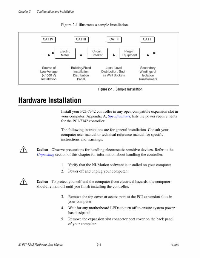
• Installation CAT IV—for measurements performed at the source of the low-voltage (<1000 V) installation. Examples include electricity meters, measurements on primary overcurrent protection devices, and ripple-control units.
• Installation CAT III—for measurements performed in the building installation. Examples include measurements on distribution boards, circuit-breakers, wiring (including cables), bus bars, junction boxes, switches, socket outlets in the fixed installation, equipment for industrial use, and some other types of equipment, such as stationary motors permanently connected to the fixed installation.
• Installation CAT II—for measurements performed on circuits directly connected to the low-voltage installation. Examples include measurements on household appliances, portable tools, and other similar equipment.
• Installation CAT I—for measurements performed on circuits not directly connected to mains1. Examples include measurements on circuits not derived from mains, and specially-protected (internal) mains-derived circuits.
1 Mains is defined as the electricity supply system to which the equipment concerned is designed to be connected for either powering the equipment or for measurement purposes.
Chapter 2 Configuration and Installation
NI PCI-7342 Hardware User Manual 2-4 ni.com
Figure 2-1 illustrates a sample installation.
Figure 2-1. Sample Installation
Hardware InstallationInstall your PCI-7342 controller in any open compatible expansion slot in your computer. Appendix A, Specifications, lists the power requirements for the PCI-7342 controller.
The following instructions are for general installation. Consult your computer user manual or technical reference manual for specific instructions and warnings.
Caution Observe precautions for handling electrostatic-sensitive devices. Refer to the Unpacking section of this chapter for information about handling the controller.
1. Verify that the NI-Motion software is installed on your computer.
2. Power off and unplug your computer.
Caution To protect yourself and the computer from electrical hazards, the computer should remain off until you finish installing the controller.
3. Remove the top cover or access port to the PCI expansion slots in your computer.
4. Wait for any motherboard LEDs to turn off to ensure system power has dissipated.
5. Remove the expansion slot connector port cover on the back panel of your computer.
Chapter 2 Configuration and Installation
© National Instruments Corporation 2-5 NI PCI-7342 Hardware User Manual
6. Insert the controller into a +3.3 V or +5 V PCI slot. Gently rock the device to ease it into place. It may be a tight fit, but do not force the device into place.
7. If available, screw the controller mounting bracket to the back panel rail of the computer.
8. Replace the cover.
9. Plug in the 68-pin cable for motion I/O to the controller.
10. Plug in and turn on your computer.
Your PCI controller is installed.
© National Instruments Corporation 3-1 NI PCI-7342 Hardware User Manual
3Hardware Overview
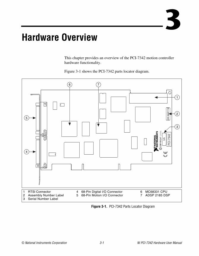
This chapter provides an overview of the PCI-7342 motion controller hardware functionality.
Figure 3-1 shows the PCI-7342 parts locator diagram.
Figure 3-1. PCI-7342 Parts Locator Diagram
1 RTSI Connector2 Assembly Number Label3 Serial Number Label
4 68-Pin Digital I/O Connector5 68-Pin Motion I/O Connector
6 MC68331 CPU7 ADSP 2185 DSP
2001
CP
CI-
7342
4
5
6 7
1
2
3
Chapter 3 Hardware Overview
NI PCI-7342 Hardware User Manual 3-2 ni.com
User ConnectorsThe 68-pin motion I/O connector provides all the signals for two axes of closed-loop motion control, including encoder feedback, limit and home inputs, breakpoint outputs, trigger inputs, and analog-to-digital (A/D) converter signals. Refer to Chapter 5, Signal Connections, for details about motion I/O connector signals.
The 68-pin digital I/O connector provides 32 bits of user-configurable digital I/O. Refer to Chapter 5, Signal Connections, for details about the digital I/O connector signals.
The RTSI connector provides up to seven triggers and one high-speed clock signal to facilitate synchronization between multiple National Instruments products. Typical applications of the RTSI bus include triggering an image acquisition or DAQ measurement based on motion events, or capturing current motion positions based on events external to the motion controller.
The RTSI bus can also be used for general-purpose I/O. Refer to Chapter 5, Signal Connections, for details about RTSI connector signals.
© National Instruments Corporation 4-1 NI PCI-7342 Hardware User Manual
4Functional Overview
This chapter provides an overview of the motion control algorithms and controller capabilities.
Dual Processor ArchitectureWith the PCI-7342 controller, you can perform one or two axes of simultaneous, coordinated motion control in a preemptive, multitasking, real-time environment.
An advanced dual-processor architecture that uses a Motorola MC68331 real-time 32-bit CPU combined with an Analog Devices ADSP 2185 DSP and custom FPGAs give the PCI-7342 controller high-performance capabilities. The FIFO bus interface and powerful function set provide high-speed communications while offloading complex motion functions from the host PC for optimized system performance.
The PCI-7342 controller uses the digital signal processor for all closed-loop control, including position tracking, PID control closed-loop computation, and motion trajectory generation. The DSP chip is supported by custom FPGAs that perform the high-speed encoder interfacing, position capture and breakpoint functions, motion I/O processing, and stepper pulse generation for hard real-time functionality.
The embedded, multitasking real-time CPU handles host communications, command processing, multi-axis interpolation, onboard program execution, error handling, general-purpose digital I/O, and overall motion system integration functions.
Chapter 4 Functional Overview
NI PCI-7342 Hardware User Manual 4-2 ni.com
Embedded Real-Time Operating System (RTOS)The embedded firmware is based upon an embedded RTOS kernel and provides optimum system performance in varying motion applications. Motion tasks are prioritized, and task execution order depends on the priority of each task, the state of the entire motion system, I/O or other system events, and the real-time clock.
The DSP chip is a separate processor that operates independently from the CPU but is closely synchronized by an internal packet-based command, data, and messaging event structure. The PCI-7342 controller is a true multiprocessing and multitasking embedded controller.
The advanced architecture of the PCI-7342 controller enables advanced motion features, such as enhanced PID functions. Refer to the NI-Motion Software Reference Manual for more information about the features available on the PCI-7342 controller.
Trajectory GeneratorsThe trajectory generators on the PCI-7342 controller calculate the instantaneous position command that controls acceleration and velocity while moving the axis to its target position. Depending on how you configure the axis, this command is sent to the PID servo loop or stepper pulse generator.
To implement infinite trajectory control, the PCI-7342 controller has four trajectory generators (two per axis) implemented in the DSP chip. Each generator calculates an instantaneous position each PID update period. While simple point-to-point moves require only one trajectory generator, blended moves and infinite trajectory control processing require two simultaneous generators.
Analog FeedbackThe PCI-7342 controller has two multiplexed, 12-bit ADC channels available for analog feedback. The converted analog values transmit to both the DSP and CPU through a dedicated internal high-speed serial bus. The multiplexer scan rate is approximately 50 µs per enabled ADC channel, which provides the high sampling rates required for feedback loop closure, joystick inputs, and monitoring analog sensors.
Chapter 4 Functional Overview
© National Instruments Corporation 4-3 NI PCI-7342 Hardware User Manual
Flash MemoryFlash ROM implements the nonvolatile memory on the PCI-7342 controller, which enables the controllers to electrically erase and reprogram its ROM. Flash memory stores all the embedded firmware, including the RTOS and DSP code, enabling you to upgrade the onboard firmware contents in the field for support and new feature enhancement.
Flash memory also allows objects such as programs and data arrays to be stored in nonvolatile memory. It is possible to save the entire parameter state of the controller to the flash memory. On the next power cycle, the controller automatically loads and returns the configuration to these new saved default values.
Flash ROM also stores the FPGA configuration programs. At power-up, the FPGAs are booted with these programs, which means that updates to the FPGA programs can be performed in the field.
Note A flash memory download utility is included with the NI-Motion software that ships with the controller.
Axes and Motion ResourcesThe PCI-7342 controller can control one or two axes of motion. The axes can be completely independent, simultaneously coordinated, or mapped in multidimensional groups called vector spaces. You can also synchronize vector spaces for multi-vector space coordinated motion control.
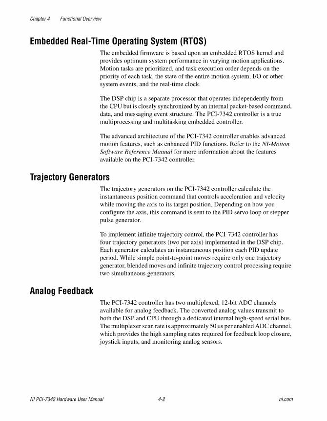
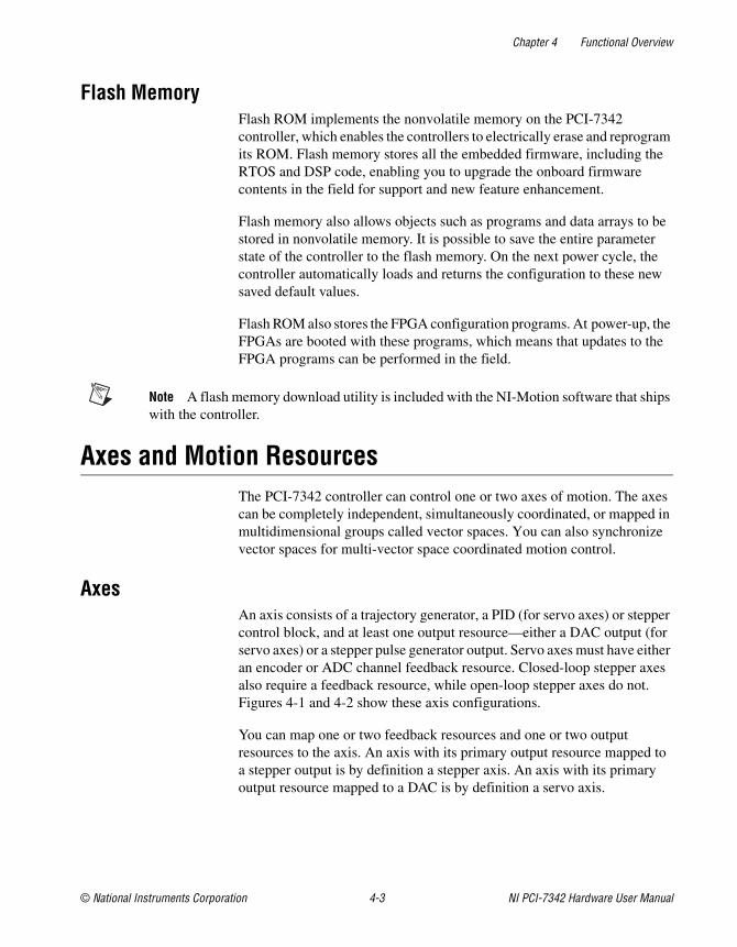
AxesAn axis consists of a trajectory generator, a PID (for servo axes) or stepper control block, and at least one output resource—either a DAC output (for servo axes) or a stepper pulse generator output. Servo axes must have either an encoder or ADC channel feedback resource. Closed-loop stepper axes also require a feedback resource, while open-loop stepper axes do not. Figures 4-1 and 4-2 show these axis configurations.
You can map one or two feedback resources and one or two output resources to the axis. An axis with its primary output resource mapped to a stepper output is by definition a stepper axis. An axis with its primary output resource mapped to a DAC is by definition a servo axis.
Chapter 4 Functional Overview
NI PCI-7342 Hardware User Manual 4-4 ni.com
Figure 4-1. Servo Axis Resources
Figure 4-2. Stepper Axis Resources
The PCI-7342 controller supports axes with secondary output resources (DACs for servo axes or stepper outputs). Defining two output resources is useful when controlling axes with multiple motors, such as gantry systems in which two DAC outputs can be configured with different torque limits and/or offsets.
The PCI-7342 controller supports secondary feedback resources (encoders) for axes defined as servo. Two feedback resources are necessary when implementing dual-loop control, such as in backlash compensation, which reduces the number of encoders available for other axes.
Note Refer to the Axis and Resource Configuration section of the NI-Motion Software Reference Manual for more information about configuring axes.
Motion ResourcesEncoder, DAC, ADC, and motion I/O resources that are not used by an axis are available for nonaxis- or nonmotion-specific applications. You can directly control an unmapped DAC as a general-purpose analog output (±10 V). Similarly, you can use any ADC channel to measure potentiometers or other analog sensors.
0101011101101 11101101100
101100111
101100111
PIDServoLoop
±10 V
øA
øB
Index
32-BitEncoderInterface
16-BitD/A
Converter
01011010 010010110
101100111
101100111
StepperControlLoop
øA
øB
Index
32-BitEncoderInterface
StepperPulse
Generator
Chapter 4 Functional Overview
© National Instruments Corporation 4-5 NI PCI-7342 Hardware User Manual
If an encoder resource is not needed for axis control, you can use it for any number of other functions, including position or velocity monitoring, as a digital potentiometer encoder input, or as a master encoder input for master/slave (electronic gearing) applications.
Each axis also has an associated forward and reverse limit input, a home input, a high-speed capture trigger input, a breakpoint output, and an inhibit output. These signals can be used for general-purpose digital I/O when not being used for their motion-specific purpose.
Note Once mapped to an axis, all features and functions of a resource are available as part of the axis. It is not necessary to remember or use the resource number directly when accessing these features. Resources are referenced by axis number once assigned to that axis.
Host CommunicationsThe host computer communicates with the controller through a number of memory port addresses on the host bus.
The primary bi-directional data transfer port is at the base address of the controller. This port supports FIFO data passing in both send and readback directions. The PCI-7342 controller has both a command buffer for incoming commands and a return data buffer (RDB) for readback data.
Two read-only status registers are at offsets from the base address. The communications status register (CSR) provides bits for communications handshaking as well as real-time error reporting and general status feedback to the host PC. The move complete status (MCS) register provides instantaneous motion status of all axes.
© National Instruments Corporation 5-1 NI PCI-7342 Hardware User Manual
5Signal Connections
This chapter describes how to send input and output signal connections directly to the controller and briefly describes the associated I/O circuitry.
The PCI-7342 controller has three connectors that handle all signals to and from the external motion system:
• 68-pin motion I/O connector
• 68-pin digital I/O connector
• RTSI connector
You can connect to your motion system with cables and accessories, varying from simple screw terminal blocks to enhanced UMI units and drives.
Caution Power off all devices when connecting or disconnecting the motion I/O and auxiliary digital I/O cables. Failure to do so may damage the controller.
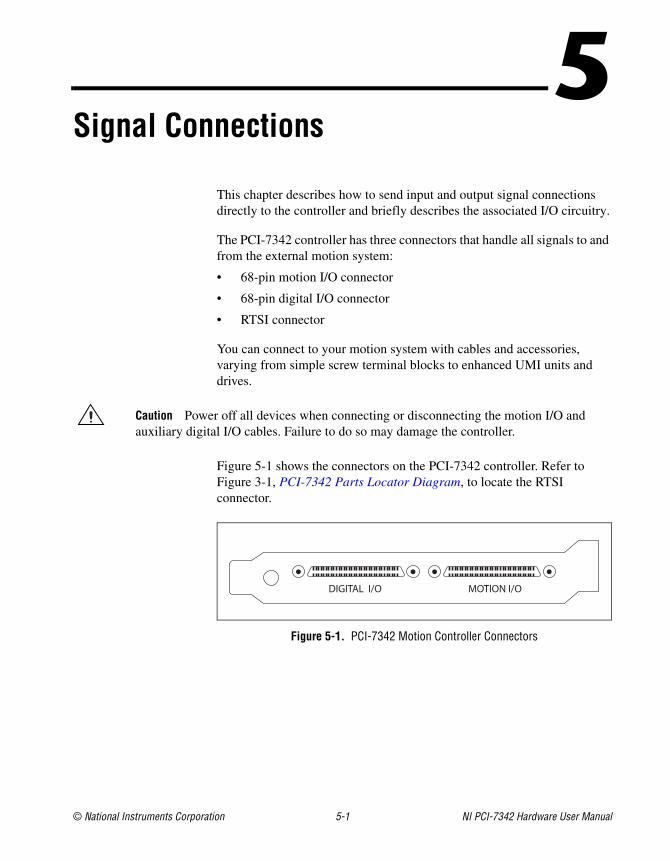
Figure 5-1 shows the connectors on the PCI-7342 controller. Refer to Figure 3-1, PCI-7342 Parts Locator Diagram, to locate the RTSI connector.
Figure 5-1. PCI-7342 Motion Controller Connectors
DIGITAL I/O MOTION I/O
Chapter 5 Signal Connections
NI PCI-7342 Hardware User Manual 5-2 ni.com
Motion I/O ConnectorThe motion I/O connector contains all signals necessary for controlling axes of servo and stepper motion, including the following features:
• Encoder feedback inputs
• Forward, home, and reverse limit inputs
• Trigger inputs
• Motor command analog and stepper outputs
• Breakpoint outputs
• Inhibit outputs
The motion I/O connector also contains two channels of 12-bit A/D inputs for analog feedback or general-purpose analog input.
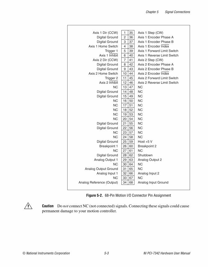
Figure 5-2 shows the pin assignments for the 68-pin motion I/O connector on the PCI-7342 controller. Refer to Table 5-1 for a description of each motion I/O signal.
Note Lines above signal names indicate that the signal is active-low.
Chapter 5 Signal Connections
© National Instruments Corporation 5-3 NI PCI-7342 Hardware User Manual
Figure 5-2. 68-Pin Motion I/O Connector Pin Assignment
Caution Do not connect NC (not connected) signals. Connecting these signals could cause permanent damage to your motion controller.
35363738394041424344454647484950515253545556575859606162636465666768
123456789
10111213141516171819202122232425262728293031323334
Axis 1 Dir (CCW)Digital GroundDigital Ground
Axis 1 Home SwitchTrigger 1
Axis 1 InhibitAxis 2 Dir (CCW)
Digital GroundDigital Ground
Axis 2 Home SwitchTrigger 2
Axis 2 InhibitNC
Digital GroundDigital Ground
NCNCNCNCNC
Digital GroundDigital Ground
NCNC
Digital GroundBreakpoint 1
NCDigital Ground
Analog Output 1NC
Analog Output GroundAnalog Input 1
NCAnalog Reference (Output)
Axis 1 Step (CW)Axis 1 Encoder Phase AAxis 1 Encoder Phase BAxis 1 Encoder IndexAxis 1 Forward Limit SwitchAxis 1 Reverse Limit SwitchAxis 2 Step (CW)Axis 2 Encoder Phase AAxis 2 Encoder Phase BAxis 2 Encoder IndexAxis 2 Forward Limit SwitchAxis 2 Reverse Limit SwitchNCNCNCNCNCNCNCNCNCNCNCNCHost +5 VBreakpoint 2NCShutdownAnalog Output 2NCNCAnalog Input 2NCAnalog Input Ground
Chapter 5 Signal Connections
NI PCI-7342 Hardware User Manual 5-4 ni.com
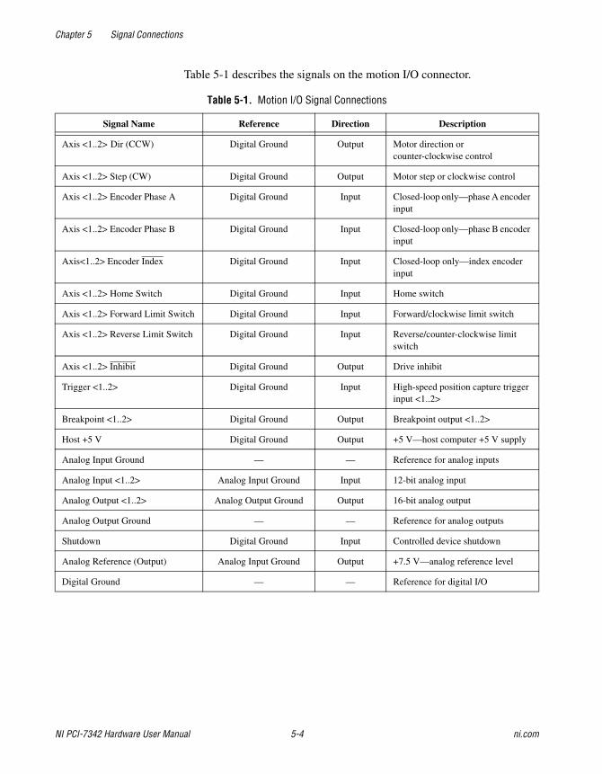
Table 5-1 describes the signals on the motion I/O connector.
Table 5-1. Motion I/O Signal Connections
Signal Name Reference Direction Description
Axis <1..2> Dir (CCW) Digital Ground Output Motor direction or counter-clockwise control
Axis <1..2> Step (CW) Digital Ground Output Motor step or clockwise control
Axis <1..2> Encoder Phase A Digital Ground Input Closed-loop only—phase A encoder input
Axis <1..2> Encoder Phase B Digital Ground Input Closed-loop only—phase B encoder input
Axis<1..2> Encoder Index Digital Ground Input Closed-loop only—index encoder input
Axis <1..2> Home Switch Digital Ground Input Home switch
Axis <1..2> Forward Limit Switch Digital Ground Input Forward/clockwise limit switch
Axis <1..2> Reverse Limit Switch Digital Ground Input Reverse/counter-clockwise limit switch
Axis <1..2> Inhibit Digital Ground Output Drive inhibit
Trigger <1..2> Digital Ground Input High-speed position capture trigger input <1..2>
Breakpoint <1..2> Digital Ground Output Breakpoint output <1..2>
Host +5 V Digital Ground Output +5 V—host computer +5 V supply
Analog Input Ground — — Reference for analog inputs
Analog Input <1..2> Analog Input Ground Input 12-bit analog input
Analog Output <1..2> Analog Output Ground Output 16-bit analog output
Analog Output Ground — — Reference for analog outputs
Shutdown Digital Ground Input Controlled device shutdown
Analog Reference (Output) Analog Input Ground Output +7.5 V—analog reference level
Digital Ground — — Reference for digital I/O
Chapter 5 Signal Connections
© National Instruments Corporation 5-5 NI PCI-7342 Hardware User Manual
Motion Axis SignalsThe following signals control the servo amplifier or stepper driver:
• Analog Output <1..2>—These 16-bit DAC outputs are typically the servo command outputs for each axis. They can drive the industry-standard ±10 V output, and you can limit them to any positive or negative voltage range desired. They also feature a software-programmable voltage offset.
Although typically used as the command output of an axis control loop, unused DACs can also function as independent analog outputs for general-purpose control.
• Analog Output Ground—This separate return connection is available to help keep digital noise separate from the analog DAC outputs. Use this analog ground connection and not Digital Ground (digital I/O reference) as the reference for the DAC outputs when connecting to servo amplifiers.
• Axis <1..2> Step (CW) and Dir (CCW)—These open-collector signals are the stepper command outputs for each axis. The PCI-7342 controller supports both major industry standards for stepper command signals: step and direction, or independent CW and CCW pulse outputs.
The output configuration and signal polarity is software programmable for compatibility with various third-party drives, as follows:
– When step and direction mode is configured, each commanded step (or microstep) produces a pulse on the step output. The direction output signal level indicates the command direction of motion, either forward or reverse.
– CW and CCW mode produces pulses (steps) on the CW output for forward-commanded motion and pulses on the CCW output for reverse-commanded motion.
In either case, you can set the active polarity of both outputs to active-low (inverting) or active-high (non-inverting). For example, with step and direction, you can make a logic high correspond to either forward or reverse direction.
The Step (CW) and Dir (CCW) outputs are driven by high-speed open-collector transistor-to-transistor (TTL) buffers that feature 64 mA sink current capability and built-in 3.3 kΩ pull-up resistors to +5 V.
Caution Do not connect these outputs to anything other than a +5 V circuit. The output buffers will fail if subjected to voltages in excess of +5.5 V.
Chapter 5 Signal Connections
NI PCI-7342 Hardware User Manual 5-6 ni.com
• Axis <1..2> Inhibit—Use the inhibit output signals to control the enable/inhibit function of a servo amplifier or stepper driver. When properly connected and configured, the inhibit function de-energizes the connected motor its shaft turns freely. These open-collector inhibit signals feature 64 mA current sink capability with built-in 3.3 kΩ pull-up resistors to +5 V, and can directly drive most driver/amplifier inhibit input circuits.
While the industry standard for inhibits is active-low (inverting), these outputs have programmable polarity and can be set to active-high (non-inverting) for increased flexibility and unique drive compatibility.
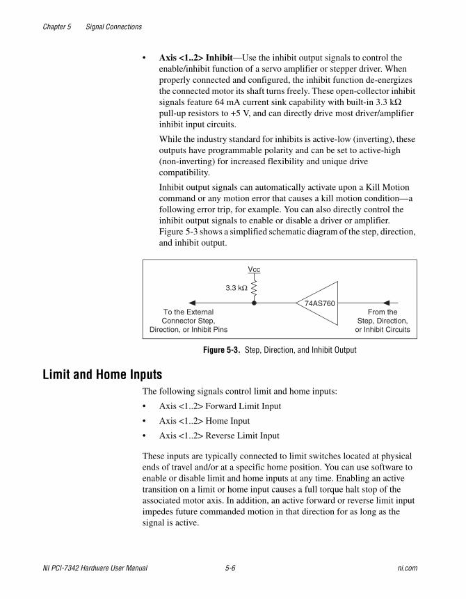
Inhibit output signals can automatically activate upon a Kill Motion command or any motion error that causes a kill motion condition—a following error trip, for example. You can also directly control the inhibit output signals to enable or disable a driver or amplifier. Figure 5-3 shows a simplified schematic diagram of the step, direction, and inhibit output.
Figure 5-3. Step, Direction, and Inhibit Output
Limit and Home InputsThe following signals control limit and home inputs:
• Axis <1..2> Forward Limit Input
• Axis <1..2> Home Input
• Axis <1..2> Reverse Limit Input
These inputs are typically connected to limit switches located at physical ends of travel and/or at a specific home position. You can use software to enable or disable limit and home inputs at any time. Enabling an active transition on a limit or home input causes a full torque halt stop of the associated motor axis. In addition, an active forward or reverse limit input impedes future commanded motion in that direction for as long as the signal is active.
To the ExternalConnector Step,
Direction, or Inhibit Pins
From theStep, Direction,
or Inhibit Circuits
74AS760
Vcc
3.3 kΩ
Chapter 5 Signal Connections
© National Instruments Corporation 5-7 NI PCI-7342 Hardware User Manual
Note Limit and home inputs are digitally filtered and must remain active for at least 1 ms to be recognized. Active signals should remain active to prevent motion from proceeding further into the limit. Pulsed limit signals stop motion but do not prevent further motion in that direction if another move is started.
The input polarity of these signals is software programmable for active-low (inverting) or active-high (non-inverting).
You can use software disabled limit and home inputs as general-purpose inputs. You can read the status of these inputs at any time and set and change their polarity as required.
Limit and home inputs are a per-axis enhancement and are not required for basic motion control. These inputs are part of a system solution for complete motion control.
Wiring ConcernsFor the end of travel limits to function correctly, the forward limit must be at the forward or positive end of travel, and the reverse limit at the negative end of travel.
Caution Failure to follow these guidelines may result in motion that stops at a limit but then travels through the limit, which could damage the motion system. Miswired limits could prevent motion from occurring at all.
Keep limit and home switch signals and their ground connections wired separately from the motor driver/amplifier signal and encoder signal connections.
Caution Wiring these signals near each other can cause faulty motion system operation due to signal noise and crosstalk.
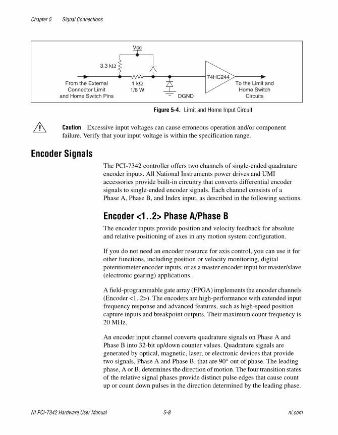
Limit and Home Input CircuitAll limit and home inputs are digitally filtered and must be active for at least 1 ms. Figure 5-4 shows a simplified schematic diagram of the circuit the limit and home switch inputs use for input signal buffering and detection.
Chapter 5 Signal Connections
NI PCI-7342 Hardware User Manual 5-8 ni.com
Figure 5-4. Limit and Home Input Circuit
Caution Excessive input voltages can cause erroneous operation and/or component failure. Verify that your input voltage is within the specification range.
Encoder SignalsThe PCI-7342 controller offers two channels of single-ended quadrature encoder inputs. All National Instruments power drives and UMI accessories provide built-in circuitry that converts differential encoder signals to single-ended encoder signals. Each channel consists of a Phase A, Phase B, and Index input, as described in the following sections.
Encoder <1..2> Phase A/Phase BThe encoder inputs provide position and velocity feedback for absolute and relative positioning of axes in any motion system configuration.
If you do not need an encoder resource for axis control, you can use it for other functions, including position or velocity monitoring, digital potentiometer encoder inputs, or as a master encoder input for master/slave (electronic gearing) applications.
A field-programmable gate array (FPGA) implements the encoder channels (Encoder <1..2>). The encoders are high-performance with extended input frequency response and advanced features, such as high-speed position capture inputs and breakpoint outputs. Their maximum count frequency is 20 MHz.
An encoder input channel converts quadrature signals on Phase A and Phase B into 32-bit up/down counter values. Quadrature signals are generated by optical, magnetic, laser, or electronic devices that provide two signals, Phase A and Phase B, that are 90° out of phase. The leading phase, A or B, determines the direction of motion. The four transition states of the relative signal phases provide distinct pulse edges that cause count up or count down pulses in the direction determined by the leading phase.
From the ExternalConnector Limit
and Home Switch Pins
To the Limit andHome Switch
Circuits
3.3 kΩ
DGND
Vcc
74HC2441 kΩ1/8 W
Chapter 5 Signal Connections
© National Instruments Corporation 5-9 NI PCI-7342 Hardware User Manual
A typical encoder with a specification of N (N = number) lines per unit of measure (revolutions or linear distance) produces 4 × N quadrature counts per unit of measure. The count is the basic increment of position in National Instruments motion systems.
Note Determine quadrature counts by multiplying the encoder resolution in encoder lines by 4. The encoder resolution is the number of encoder lines between consecutive encoder indexes (marker or Z-bit). If the encoder does not have an index output, the resolution is referred to as lines per revolution, or lines per unit of measure—inch, centimeter, millimeter, and so on.
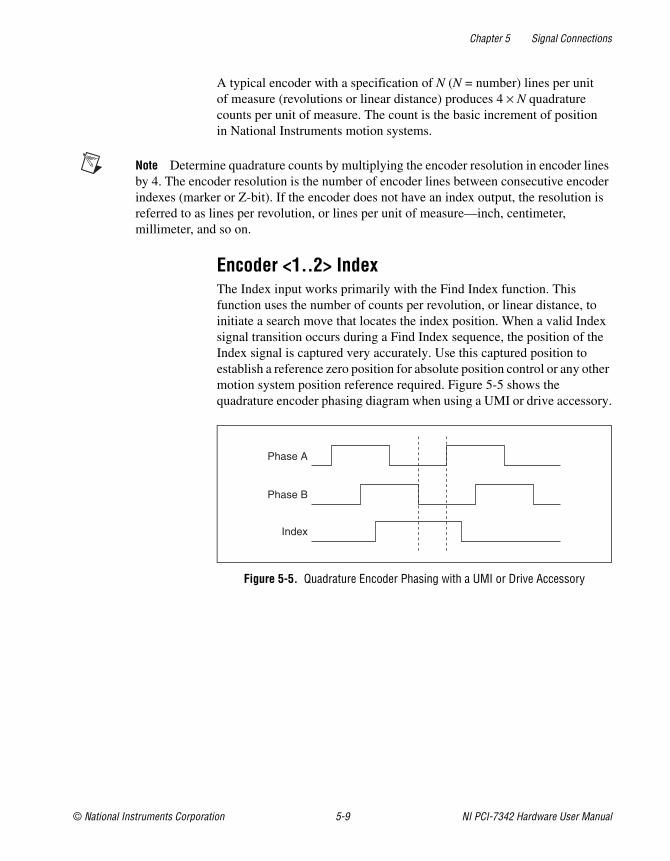
Encoder <1..2> IndexThe Index input works primarily with the Find Index function. This function uses the number of counts per revolution, or linear distance, to initiate a search move that locates the index position. When a valid Index signal transition occurs during a Find Index sequence, the position of the Index signal is captured very accurately. Use this captured position to establish a reference zero position for absolute position control or any other motion system position reference required. Figure 5-5 shows the quadrature encoder phasing diagram when using a UMI or drive accessory.
Figure 5-5. Quadrature Encoder Phasing with a UMI or Drive Accessory
Phase A
Phase B
Index
Chapter 5 Signal Connections
NI PCI-7342 Hardware User Manual 5-10 ni.com
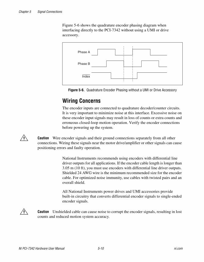
Figure 5-6 shows the quadrature encoder phasing diagram when interfacing directly to the PCI-7342 without using a UMI or drive accessory.
Figure 5-6. Quadrature Encoder Phasing without a UMI or Drive Accessory
Wiring ConcernsThe encoder inputs are connected to quadrature decoder/counter circuits. It is very important to minimize noise at this interface. Excessive noise on these encoder input signals may result in loss of counts or extra counts and erroneous closed-loop motion operation. Verify the encoder connections before powering up the system.
Caution Wire encoder signals and their ground connections separately from all other connections. Wiring these signals near the motor drive/amplifier or other signals can cause positioning errors and faulty operation.
National Instruments recommends using encoders with differential line driver outputs for all applications. If the encoder cable length is longer than 3.05 m (10 ft), you must use encoders with differential line driver outputs. Shielded 24 AWG wire is the minimum recommended size for the encoder cable. For optimized noise immunity, use cables with twisted pairs and an overall shield.
All National Instruments power drives and UMI accessories provide built-in circuitry that converts differential encoder signals to single-ended encoder signals.
Caution Unshielded cable can cause noise to corrupt the encoder signals, resulting in lost counts and reduced motion system accuracy.
Phase A
Phase B
Index
Chapter 5 Signal Connections
© National Instruments Corporation 5-11 NI PCI-7342 Hardware User Manual
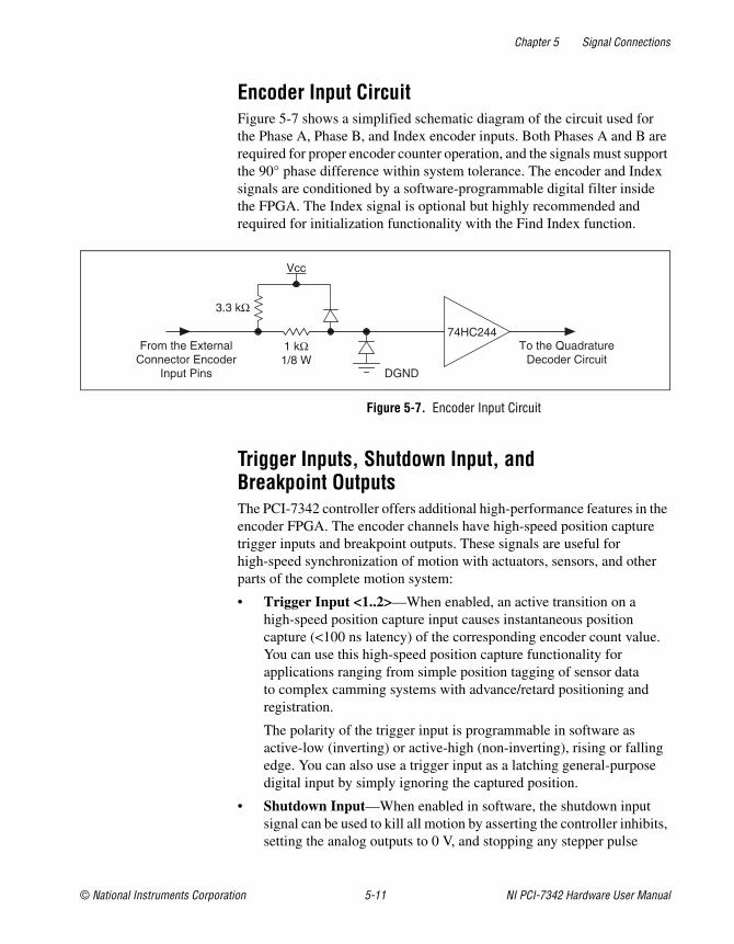
Encoder Input CircuitFigure 5-7 shows a simplified schematic diagram of the circuit used for the Phase A, Phase B, and Index encoder inputs. Both Phases A and B are required for proper encoder counter operation, and the signals must support the 90° phase difference within system tolerance. The encoder and Index signals are conditioned by a software-programmable digital filter inside the FPGA. The Index signal is optional but highly recommended and required for initialization functionality with the Find Index function.
Figure 5-7. Encoder Input Circuit
Trigger Inputs, Shutdown Input, and Breakpoint OutputsThe PCI-7342 controller offers additional high-performance features in the encoder FPGA. The encoder channels have high-speed position capture trigger inputs and breakpoint outputs. These signals are useful for high-speed synchronization of motion with actuators, sensors, and other parts of the complete motion system:
• Trigger Input <1..2>—When enabled, an active transition on a high-speed position capture input causes instantaneous position capture (<100 ns latency) of the corresponding encoder count value. You can use this high-speed position capture functionality for applications ranging from simple position tagging of sensor data to complex camming systems with advance/retard positioning and registration.
The polarity of the trigger input is programmable in software as active-low (inverting) or active-high (non-inverting), rising or falling edge. You can also use a trigger input as a latching general-purpose digital input by simply ignoring the captured position.
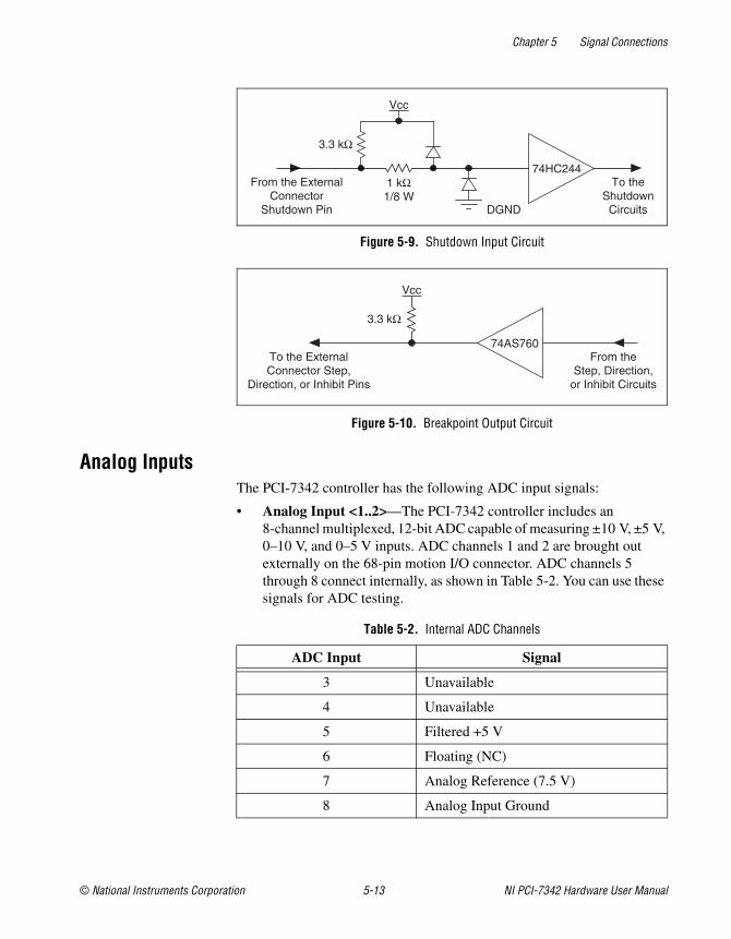
• Shutdown Input—When enabled in software, the shutdown input signal can be used to kill all motion by asserting the controller inhibits, setting the analog outputs to 0 V, and stopping any stepper pulse
From the ExternalConnector Encoder
Input Pins
To the QuadratureDecoder Circuit
3.3 kΩ
DGND
Vcc
74HC2441 kΩ1/8 W
Chapter 5 Signal Connections
NI PCI-7342 Hardware User Manual 5-12 ni.com
generation. To activate shutdown, the signal must transition from a low to high state (rising edge). Shutdown occurs when a rising edge is detected on the shutdown line.
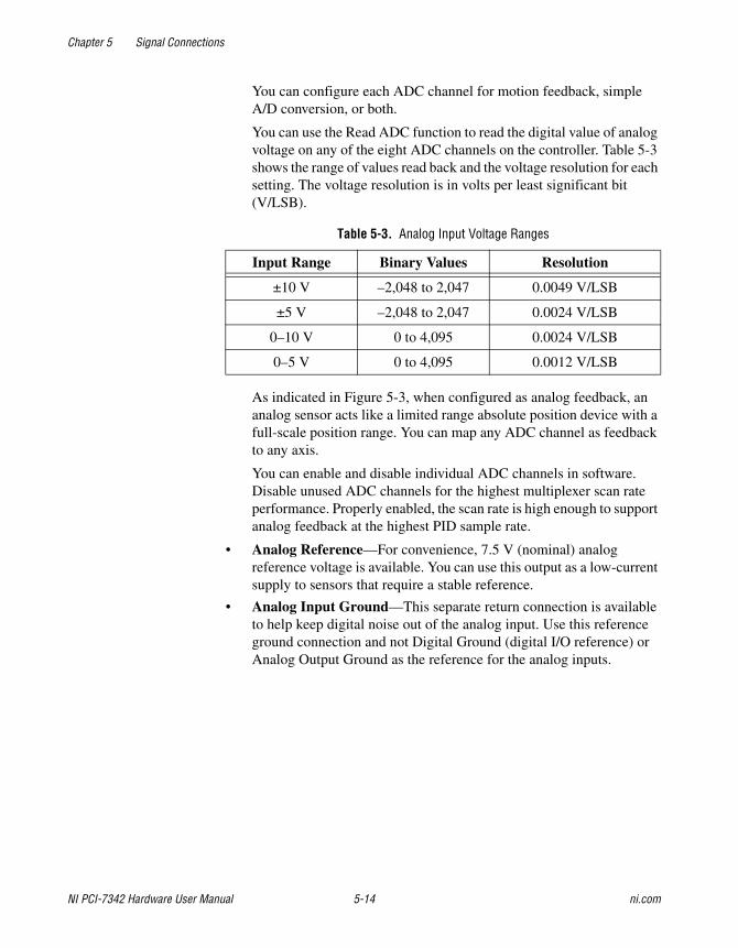
• Breakpoint Output <1..2>—You can program a breakpoint output to transition when the associated encoder value equals the breakpoint position. You can use a breakpoint output to directly control actuators or as a trigger to synchronize data acquisition or other functions in the motion control system.
You can program breakpoints as either absolute, modulo, or relative position. You can preset breakpoint outputs to a known state so that when the breakpoint occurs the transition is low to high, high to low, or toggled.
Open-collector TTL buffers drive the breakpoint outputs. These buffers feature 64 mA sink current capability and built-in 3.3 kΩ pull-up resistors to +5 V.
You can directly set and reset breakpoint outputs to use as general-purpose digital outputs.
Wiring Concerns
Caution Keep trigger input, shutdown input, and breakpoint output signals and their ground connections wired separately from the motor driver/amplifier signal and encoder signal connections. Wiring these signals near each other can cause faulty operation. Excessive input voltages can cause erroneous operation and/or component failure.
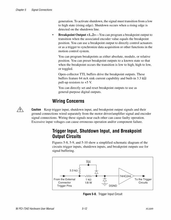
Trigger Input, Shutdown Input, and Breakpoint Output CircuitsFigures 5-8, 5-9, and 5-10 show a simplified schematic diagram of the circuits trigger inputs, shutdown inputs, and breakpoint outputs use for signal buffering.
Figure 5-8. Trigger Input Circuit
From the ExternalConnector
Trigger Pins
To the TriggerCircuits
3.3 kΩ
DGND
Vcc
74HC2441 kΩ1/8 W
Chapter 5 Signal Connections
© National Instruments Corporation 5-13 NI PCI-7342 Hardware User Manual
Figure 5-9. Shutdown Input Circuit
Figure 5-10. Breakpoint Output Circuit
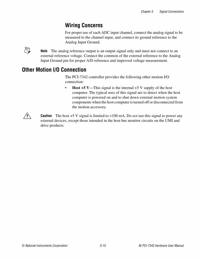
Analog InputsThe PCI-7342 controller has the following ADC input signals:
• Analog Input <1..2>—The PCI-7342 controller includes an 8-channel multiplexed, 12-bit ADC capable of measuring ±10 V, ±5 V, 0–10 V, and 0–5 V inputs. ADC channels 1 and 2 are brought out externally on the 68-pin motion I/O connector. ADC channels 5 through 8 connect internally, as shown in Table 5-2. You can use these signals for ADC testing.
Table 5-2. Internal ADC Channels
ADC Input Signal
3 Unavailable
4 Unavailable
5 Filtered +5 V
6 Floating (NC)
7 Analog Reference (7.5 V)
8 Analog Input Ground
From the ExternalConnector
Shutdown Pin
To theShutdown
Circuits
3.3 kΩ
DGND
Vcc
74HC2441 kΩ1/8 W
To the ExternalConnector Step,
Direction, or Inhibit Pins
From theStep, Direction,
or Inhibit Circuits
74AS760
Vcc
3.3 kΩ
Chapter 5 Signal Connections
NI PCI-7342 Hardware User Manual 5-14 ni.com
You can configure each ADC channel for motion feedback, simple A/D conversion, or both.
You can use the Read ADC function to read the digital value of analog voltage on any of the eight ADC channels on the controller. Table 5-3 shows the range of values read back and the voltage resolution for each setting. The voltage resolution is in volts per least significant bit (V/LSB).
As indicated in Figure 5-3, when configured as analog feedback, an analog sensor acts like a limited range absolute position device with a full-scale position range. You can map any ADC channel as feedback to any axis.
You can enable and disable individual ADC channels in software. Disable unused ADC channels for the highest multiplexer scan rate performance. Properly enabled, the scan rate is high enough to support analog feedback at the highest PID sample rate.
• Analog Reference—For convenience, 7.5 V (nominal) analog reference voltage is available. You can use this output as a low-current supply to sensors that require a stable reference.
• Analog Input Ground—This separate return connection is available to help keep digital noise out of the analog input. Use this reference ground connection and not Digital Ground (digital I/O reference) or Analog Output Ground as the reference for the analog inputs.
Table 5-3. Analog Input Voltage Ranges
Input Range Binary Values Resolution
±10 V –2,048 to 2,047 0.0049 V/LSB
±5 V –2,048 to 2,047 0.0024 V/LSB
0–10 V 0 to 4,095 0.0024 V/LSB
0–5 V 0 to 4,095 0.0012 V/LSB
Chapter 5 Signal Connections
© National Instruments Corporation 5-15 NI PCI-7342 Hardware User Manual
Wiring ConcernsFor proper use of each ADC input channel, connect the analog signal to be measured to the channel input, and connect its ground reference to the Analog Input Ground.
Note The analog reference output is an output signal only and must not connect to an external reference voltage. Connect the common of the external reference to the Analog Input Ground pin for proper A/D reference and improved voltage measurement.
Other Motion I/O ConnectionThe PCI-7342 controller provides the following other motion I/O connection:
• Host +5 V—This signal is the internal +5 V supply of the host computer. The typical uses of this signal are to detect when the host computer is powered on and to shut down external motion system components when the host computer is turned off or disconnected from the motion accessory.
Caution The host +5 V signal is limited to <100 mA. Do not use this signal to power any external devices, except those intended in the host bus monitor circuits on the UMI and drive products.
Chapter 5 Signal Connections
NI PCI-7342 Hardware User Manual 5-16 ni.com
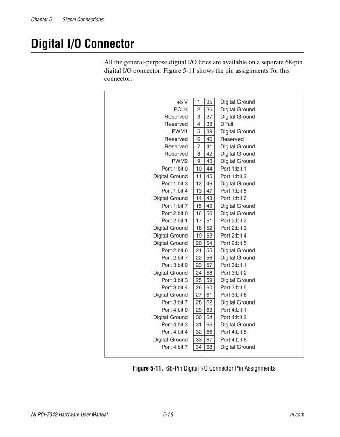
Digital I/O ConnectorAll the general-purpose digital I/O lines are available on a separate 68-pin digital I/O connector. Figure 5-11 shows the pin assignments for this connector.
Figure 5-11. 68-Pin Digital I/O Connector Pin Assignments
35363738394041424344454647484950515253545556575859606162636465666768
123456789
10111213141516171819202122232425262728293031323334
+5 VPCLK
ReservedReserved
PWM1ReservedReservedReserved
PWM2Port 1:bit 0
Digital GroundPort 1:bit 3Port 1:bit 4
Digital GroundPort 1:bit 7Port 2:bit 0Port 2:bit 1
Digital GroundDigital GroundDigital Ground
Port 2:bit 6Port 2:bit 7Port 3:bit 0
Digital GroundPort 3:bit 3Port 3:bit 4
Digital GroundPort 3:bit 7Port 4:bit 0
Digital GroundPort 4:bit 3Port 4:bit 4
Digital GroundPort 4:bit 7
Digital GroundDigital GroundDigital GroundDPullDigital GroundReservedDigital GroundDigital GroundDigital GroundPort 1:bit 1Port 1:bit 2Digital GroundPort 1:bit 5Port 1:bit 6Digital GroundDigital GroundPort 2:bit 2Port 2:bit 3Port 2:bit 4Port 2:bit 5Digital GroundDigital GroundPort 3:bit 1Port 3:bit 2Digital GroundPort 3:bit 5Port 3:bit 6Digital GroundPort 4:bit 1Port 4:bit 2Digital GroundPort 4:bit 5Port 4:bit 6Digital Ground
Chapter 5 Signal Connections
© National Instruments Corporation 5-17 NI PCI-7342 Hardware User Manual
The 32-bit digital I/O port is configured in hardware as four 8-bit digital I/O ports. The bits in a port are typically controlled and read with byte-wide bitmapped commands.
All digital I/O lines have programmable direction and polarity. Each output circuit can sink and source 24 mA.
The DPull pin controls the state of the input pins at power-up. Connecting DPull to +5 V or leaving it unconnected configures all pins in all ports for 100 kΩ pull-ups. Connecting DPull to ground configures the ports for 100 kΩ pull-downs.
PWM FeaturesThe PCI-7342 controller provides two pulse-width modulation (PWM) outputs on the digital I/O connector. The PWM outputs generate periodic waveforms whose period and duty cycles can be independently controlled through software commands. PWM is a digital representation of an analog value, because the duty cycle is directly proportional to the desired output value. The typical use of PWM outputs is to transmit an analog value through an optocoupler. A simple lowpass filter turns a PWM signal back into its corresponding analog value. If desired, you can use the PCLK input instead of the internal source as the clock for the PWM generators.
Note These signals are configured in software and are in no way associated with the PID servo control loop. Refer to your NI-Motion Software Reference Manual for more information about PWM signals.
RTSI ConnectorThe RTSI bus on PCI-7342 is connected with a ribbon cable to National Instruments DAQ and IMAQ PCI devices that have RTSI capability.
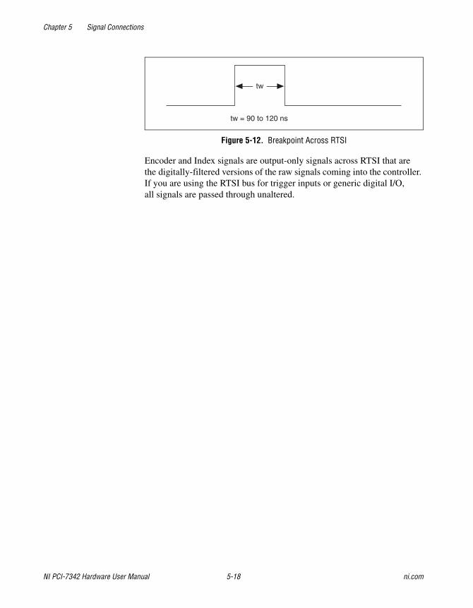
RTSI Signal ConsiderationsThe PCI-7342 motion controller allows you to use the RTSI signals as sources for trigger inputs, or as destinations for breakpoint outputs and encoder signals. The RTSI bus can also serve as a generic digital I/O port. Breakpoint outputs are output-only signals that generate an active-high pulse of 90 to 120 ns duration, as shown in Figure 5-12.
Chapter 5 Signal Connections
NI PCI-7342 Hardware User Manual 5-18 ni.com
Figure 5-12. Breakpoint Across RTSI
Encoder and Index signals are output-only signals across RTSI that are the digitally-filtered versions of the raw signals coming into the controller. If you are using the RTSI bus for trigger inputs or generic digital I/O, all signals are passed through unaltered.
tw
tw = 90 to 120 ns
© National Instruments Corporation A-1 NI PCI-7342 Hardware User Manual
ASpecifications
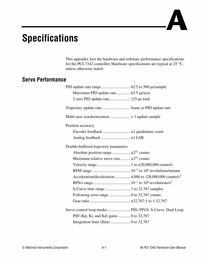
This appendix lists the hardware and software performance specifications for the PCI-7342 controller. Hardware specifications are typical at 25 °C, unless otherwise stated.
Servo PerformancePID update rate range............................. 62.5 to 500 µs/sample
Maximum PID update rate.............. 62.5 µs/axis
2-axis PID update rate..................... 125 µs total
Trajectory update rate ............................ Same as PID update rate
Multi-axis synchronization .................... < 1 update sample
Position accuracy
Encoder feedback............................ ±1 quadrature count
Analog feedback ............................. ±1 LSB
Double-buffered trajectory parameters
Absolute position range .................. ±231 counts
Maximum relative move size.......... ±231 counts
Velocity range................................. 1 to ±20,000,000 counts/s
RPM range ...................................... 10–5 to 106 revolutions/minute
Acceleration/deceleration ............... 4,000 to 128,000,000 counts/s2
RPS/s range..................................... 10–1 to 108 revolutions/s2
S-Curve time range ......................... 1 to 32,767 samples
Following error range ..................... 0 to 32,767 counts
Gear ratio ........................................ ±32,767:1 to 1:32,767
Servo control loop modes ...................... PID, PIVff, S-Curve, Dual Loop
PID (Kp, Ki, and Kd) gains ............ 0 to 32,767
Integration limit (Ilim) .................... 0 to 32,767
Appendix A Specifications
NI PCI-7342 Hardware User Manual A-2 ni.com
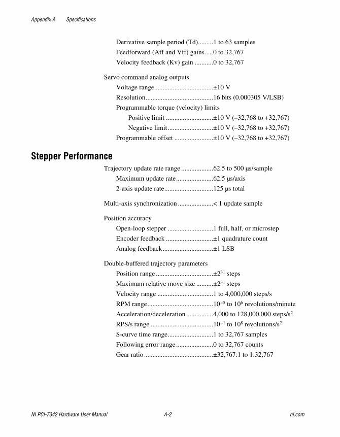
Derivative sample period (Td).........1 to 63 samples
Feedforward (Aff and Vff) gains.....0 to 32,767
Velocity feedback (Kv) gain ...........0 to 32,767
Servo command analog outputs
Voltage range...................................±10 V
Resolution........................................16 bits (0.000305 V/LSB)
Programmable torque (velocity) limits
Positive limit ............................±10 V (–32,768 to +32,767)
Negative limit ...........................±10 V (–32,768 to +32,767)
Programmable offset .......................±10 V (–32,768 to +32,767)
Stepper PerformanceTrajectory update rate range ...................62.5 to 500 µs/sample
Maximum update rate......................62.5 µs/axis
2-axis update rate.............................125 µs total
Multi-axis synchronization .....................< 1 update sample
Position accuracy
Open-loop stepper ...........................1 full, half, or microstep
Encoder feedback ............................±1 quadrature count
Analog feedback..............................±1 LSB
Double-buffered trajectory parameters
Position range ..................................±231 steps
Maximum relative move size ..........±231 steps
Velocity range .................................1 to 4,000,000 steps/s
RPM range.......................................10–5 to 106 revolutions/minute
Acceleration/deceleration ................4,000 to 128,000,000 steps/s2
RPS/s range .....................................10–1 to 108 revolutions/s2
S-curve time range...........................1 to 32,767 samples
Following error range ......................0 to 32,767 counts
Gear ratio .........................................±32,767:1 to 1:32,767
Appendix A Specifications
© National Instruments Corporation A-3 NI PCI-7342 Hardware User Manual
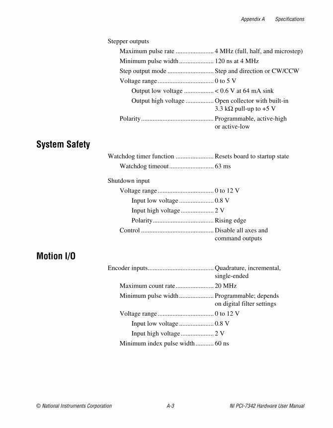
Stepper outputs
Maximum pulse rate ....................... 4 MHz (full, half, and microstep)
Minimum pulse width ..................... 120 ns at 4 MHz
Step output mode ............................ Step and direction or CW/CCW
Voltage range.................................. 0 to 5 V
Output low voltage .................. < 0.6 V at 64 mA sink
Output high voltage ................. Open collector with built-in 3.3 kΩ pull-up to +5 V
Polarity............................................ Programmable, active-high or active-low
System SafetyWatchdog timer function ....................... Resets board to startup state
Watchdog timeout........................... 63 ms
Shutdown input
Voltage range.................................. 0 to 12 V
Input low voltage ..................... 0.8 V
Input high voltage .................... 2 V
Polarity..................................... Rising edge
Control ............................................ Disable all axes and command outputs
Motion I/OEncoder inputs........................................ Quadrature, incremental,
single-ended
Maximum count rate ....................... 20 MHz
Minimum pulse width ..................... Programmable; depends on digital filter settings
Voltage range.................................. 0 to 12 V
Input low voltage ..................... 0.8 V
Input high voltage .................... 2 V
Minimum index pulse width ........... 60 ns
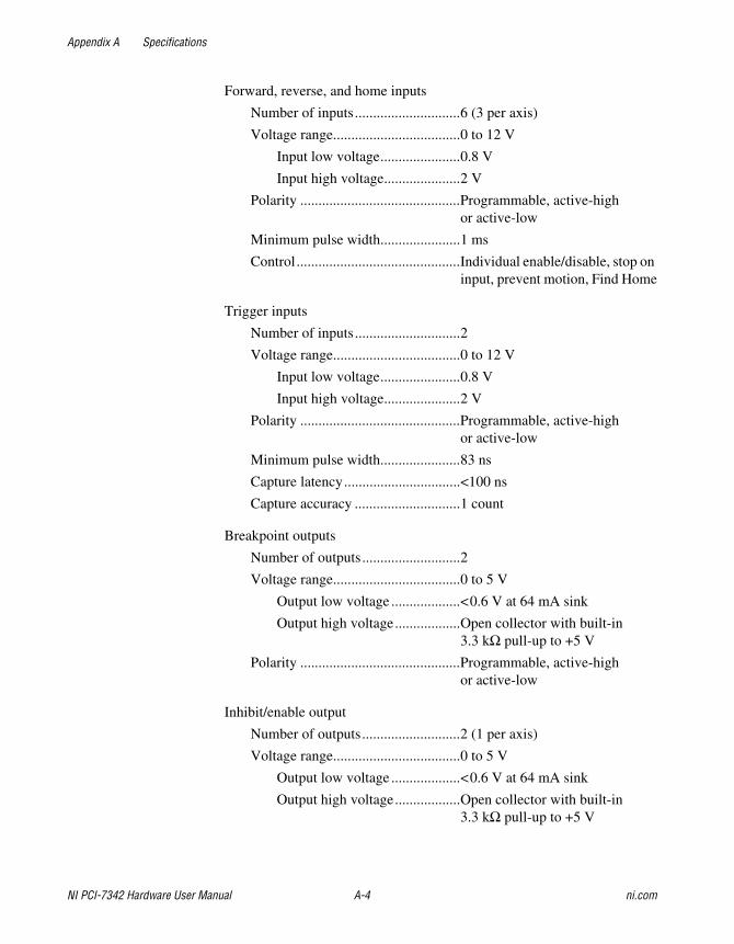
Appendix A Specifications
NI PCI-7342 Hardware User Manual A-4 ni.com
Forward, reverse, and home inputs
Number of inputs.............................6 (3 per axis)
Voltage range...................................0 to 12 V
Input low voltage......................0.8 V
Input high voltage.....................2 V
Polarity ............................................Programmable, active-high or active-low
Minimum pulse width......................1 ms
Control.............................................Individual enable/disable, stop on input, prevent motion, Find Home
Trigger inputs
Number of inputs.............................2
Voltage range...................................0 to 12 V
Input low voltage......................0.8 V
Input high voltage.....................2 V
Polarity ............................................Programmable, active-high or active-low
Minimum pulse width......................83 ns
Capture latency................................<100 ns
Capture accuracy .............................1 count
Breakpoint outputs
Number of outputs...........................2
Voltage range...................................0 to 5 V
Output low voltage ...................<0.6 V at 64 mA sink
Output high voltage..................Open collector with built-in 3.3 kΩ pull-up to +5 V
Polarity ............................................Programmable, active-high or active-low
Inhibit/enable output
Number of outputs...........................2 (1 per axis)
Voltage range...................................0 to 5 V
Output low voltage ...................<0.6 V at 64 mA sink
Output high voltage..................Open collector with built-in 3.3 kΩ pull-up to +5 V
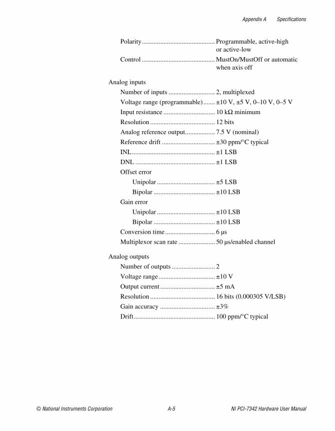
Appendix A Specifications
© National Instruments Corporation A-5 NI PCI-7342 Hardware User Manual
Polarity............................................ Programmable, active-high or active-low
Control ............................................ MustOn/MustOff or automatic when axis off
Analog inputs
Number of inputs ............................ 2, multiplexed
Voltage range (programmable) ....... ±10 V, ±5 V, 0–10 V, 0–5 V
Input resistance ............................... 10 kΩ minimum
Resolution ....................................... 12 bits
Analog reference output.................. 7.5 V (nominal)
Reference drift ................................ ±30 ppm/°C typical
INL.................................................. ±1 LSB
DNL ................................................ ±1 LSB
Offset error
Unipolar ................................... ±5 LSB
Bipolar ..................................... ±10 LSB
Gain error
Unipolar ................................... ±10 LSB
Bipolar ..................................... ±10 LSB
Conversion time.............................. 6 µs
Multiplexor scan rate ...................... 50 µs/enabled channel
Analog outputs
Number of outputs .......................... 2
Voltage range.................................. ±10 V
Output current ................................. ±5 mA
Resolution ....................................... 16 bits (0.000305 V/LSB)
Gain accuracy ................................. ±3%
Drift................................................. 100 ppm/°C typical
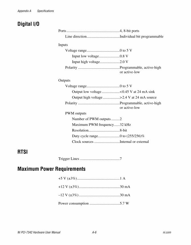
Appendix A Specifications
NI PCI-7342 Hardware User Manual A-6 ni.com
Digital I/OPorts ........................................................4, 8-bit ports
Line direction...................................Individual bit programmable
Inputs
Voltage range...................................0 to 5 V
Input low voltage......................0.8 V
Input high voltage.....................2.0 V
Polarity ............................................Programmable, active-high or active-low
Outputs
Voltage range...................................0 to 5 V
Output low voltage ...................<0.45 V at 24 mA sink
Output high voltage..................>2.4 V at 24 mA source
Polarity ............................................Programmable, active-high or active-low
PWM outputs
Number of PWM outputs .........2
Maximum PWM frequency......32 kHz
Resolution.................................8-bit
Duty cycle range.......................0 to (255/256)%
Clock sources ...........................Internal or external
RTSITrigger Lines ..........................................7
Maximum Power Requirements
+5 V (±3%).............................................1 A
+12 V (±3%)...........................................30 mA
–12 V (±3%) ...........................................30 mA
Power consumption ................................5.7 W
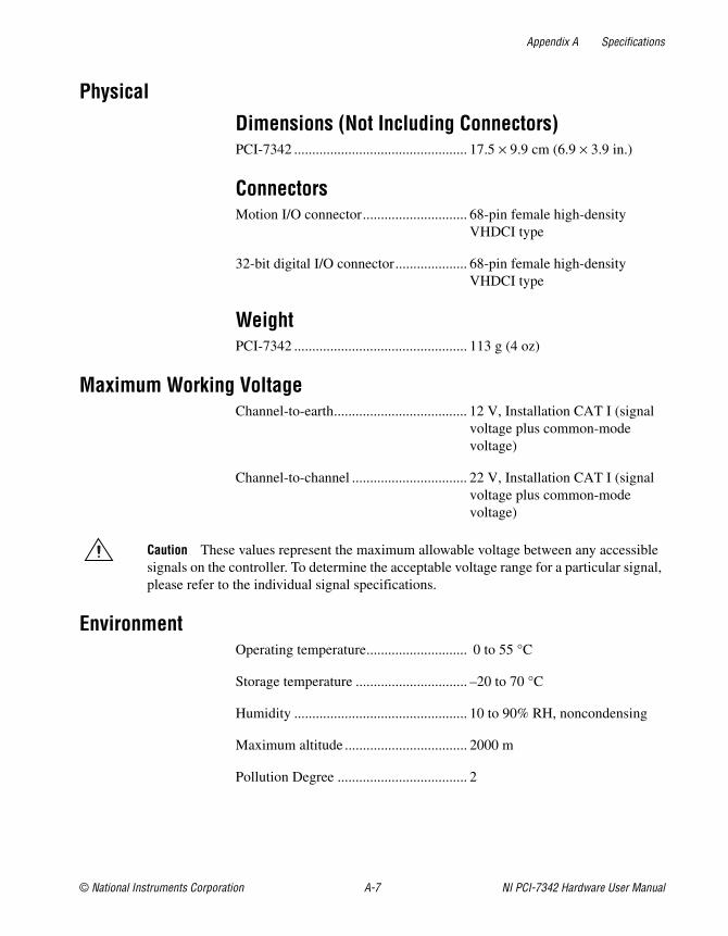
Appendix A Specifications
© National Instruments Corporation A-7 NI PCI-7342 Hardware User Manual
Physical
Dimensions (Not Including Connectors)PCI-7342 ................................................ 17.5 × 9.9 cm (6.9 × 3.9 in.)
ConnectorsMotion I/O connector............................. 68-pin female high-density
VHDCI type
32-bit digital I/O connector.................... 68-pin female high-density VHDCI type
WeightPCI-7342 ................................................ 113 g (4 oz)
Maximum Working Voltage Channel-to-earth..................................... 12 V, Installation CAT I (signal
voltage plus common-mode voltage)
Channel-to-channel ................................ 22 V, Installation CAT I (signal voltage plus common-mode voltage)
Caution These values represent the maximum allowable voltage between any accessible signals on the controller. To determine the acceptable voltage range for a particular signal, please refer to the individual signal specifications.
EnvironmentOperating temperature............................ 0 to 55 °C
Storage temperature ............................... –20 to 70 °C
Humidity ................................................ 10 to 90% RH, noncondensing
Maximum altitude .................................. 2000 m
Pollution Degree .................................... 2
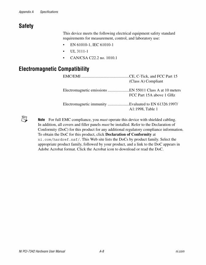
Appendix A Specifications
NI PCI-7342 Hardware User Manual A-8 ni.com
SafetyThis device meets the following electrical equipment safety standard requirements for measurement, control, and laboratory use:
• EN 61010-1, IEC 61010-1
• UL 3111-1
• CAN/CSA C22.2 no. 1010.1
Electromagnetic CompatibilityEMC/EMI ...............................................CE, C-Tick, and FCC Part 15
(Class A) Compliant
Electromagnetic emissions .....................EN 55011 Class A at 10 metersFCC Part 15A above 1 GHz
Electromagnetic immunity .....................Evaluated to EN 61326:1997/ A1:1998, Table 1
Note For full EMC compliance, you must operate this device with shielded cabling. In addition, all covers and filler panels must be installed. Refer to the Declaration of Conformity (DoC) for this product for any additional regulatory compliance information. To obtain the DoC for this product, click Declaration of Conformity at ni.com/hardref.nsf/. This Web site lists the DoCs by product family. Select the appropriate product family, followed by your product, and a link to the DoC appears in Adobe Acrobat format. Click the Acrobat icon to download or read the DoC.
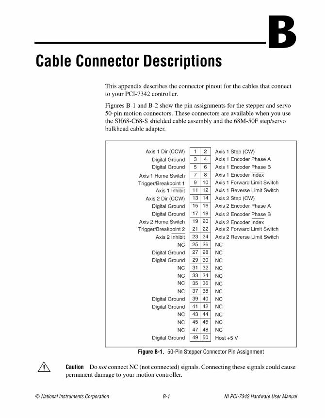
© National Instruments Corporation B-1 NI PCI-7342 Hardware User Manual
BCable Connector Descriptions
This appendix describes the connector pinout for the cables that connect to your PCI-7342 controller.
Figures B-1 and B-2 show the pin assignments for the stepper and servo 50-pin motion connectors. These connectors are available when you use the SH68-C68-S shielded cable assembly and the 68M-50F step/servo bulkhead cable adapter.
Figure B-1. 50-Pin Stepper Connector Pin Assignment
Caution Do not connect NC (not connected) signals. Connecting these signals could cause permanent damage to your motion controller.
Digital Ground
NC
NC
NC
Digital Ground
Digital Ground
NC
NCNC
NC
Digital Ground
Digital Ground
NC
Axis 2 Inhibit
Trigger/Breakpoint 2Axis 2 Home Switch
Digital Ground
Digital Ground
Axis 2 Dir (CCW)
Axis 1 InhibitTrigger/Breakpoint 1
Axis 1 Home Switch
Digital GroundDigital Ground
Axis 1 Dir (CCW)
Host +5 V
NC
NC
NC
NC
NC
NC
NC
NC
NC
NC
NC
NC
Axis 2 Reverse Limit Switch
Axis 2 Forward Limit SwitchAxis 2 Encoder Index
Axis 2 Encoder Phase B
Axis 2 Encoder Phase A
Axis 2 Step (CW)
Axis 1 Reverse Limit Switch
Axis 1 Forward Limit Switch
Axis 1 Encoder Index
Axis 1 Encoder Phase B
Axis 1 Encoder Phase A
Axis 1 Step (CW)
49 50
47 48
45 46
43 44
41 42
39 40
37 38
35 36
33 34
31 32
29 30
27 28
25 26
23 24
21 22
19 20
17 18
15 16
13 14
11 12
9 10
7 8
5 6
3 4
1 2
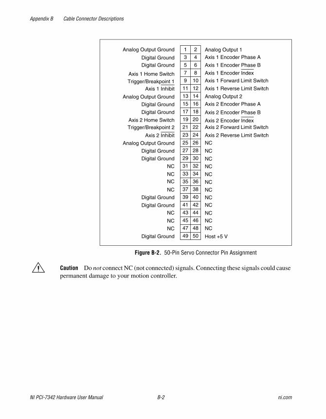
Appendix B Cable Connector Descriptions
NI PCI-7342 Hardware User Manual B-2 ni.com
Figure B-2. 50-Pin Servo Connector Pin Assignment
Caution Do not connect NC (not connected) signals. Connecting these signals could cause permanent damage to your motion controller.
Digital Ground
NC
NC
NC
Digital Ground
Digital Ground
NC
NCNC
NC
Digital Ground
Digital Ground
Analog Output Ground
Axis 2 Inhibit
Trigger/Breakpoint 2Axis 2 Home Switch
Digital Ground
Digital Ground
Analog Output Ground
Axis 1 InhibitTrigger/Breakpoint 1
Axis 1 Home Switch
Digital GroundDigital Ground
Analog Output Ground
Host +5 V
NC
NC
NC
NC
NC
NC
NC
NC
NC
NC
NC
NC
Axis 2 Reverse Limit Switch
Axis 2 Forward Limit SwitchAxis 2 Encoder Index
Axis 2 Encoder Phase B
Axis 2 Encoder Phase A
Analog Output 2
Axis 1 Reverse Limit Switch
Axis 1 Forward Limit Switch
Axis 1 Encoder Index
Axis 1 Encoder Phase B
Axis 1 Encoder Phase A
Analog Output 1
49 50
47 48
45 46
43 44
41 42
39 40
37 38
35 36
33 34
31 32
29 30
27 28
25 26
23 24
21 22
19 20
17 18
15 16
13 14
11 12
9 10
7 8
5 6
3 4
1 2
© National Instruments Corporation C-1 NI PCI-7342 Hardware User Manual
CTechnical Support and Professional Services
Visit the following sections of the National Instruments Web site at ni.com for technical support and professional services:
• Support—Online technical support resources include the following:
– Self-Help Resources—For immediate answers and solutions, visit our extensive library of technical support resources available in English, Japanese, and Spanish at ni.com/support. These resources are available for most products at no cost to registered users and include software drivers and updates, a KnowledgeBase, product manuals, step-by-step troubleshooting wizards, hardware schematics and conformity documentation, example code, tutorials and application notes, instrument drivers, discussion forums, a measurement glossary, and so on.
– Assisted Support Options—Contact NI engineers and other measurement and automation professionals by visiting ni.com/ask. Our online system helps you define your question and connects you to the experts by phone, discussion forum, or email.
• Training—Visit ni.com/custed for self-paced tutorials, videos, and interactive CDs. You also can register for instructor-led, hands-on courses at locations around the world.
• System Integration—If you have time constraints, limited in-house technical resources, or other project challenges, NI Alliance Program members can help. To learn more, call your local NI office or visit ni.com/alliance.
If you searched ni.com and could not find the answers you need, contact your local office or NI corporate headquarters. Phone numbers for our worldwide offices are listed at the front of this manual. You also can visit the Worldwide Offices section of ni.com/niglobal to access the branch office Web sites, which provide up-to-date contact information, support phone numbers, email addresses, and current events.
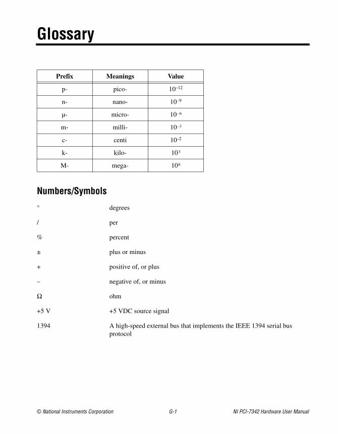
© National Instruments Corporation G-1 NI PCI-7342 Hardware User Manual
Glossary
Prefix Meanings Value
p- pico- 10–12
n- nano- 10–9
µ- micro- 10– 6
m- milli- 10–3
c- centi 10–2
k- kilo- 103
M- mega- 106
Numbers/Symbols
° degrees
/ per
% percent
± plus or minus
+ positive of, or plus
– negative of, or minus
Ω ohm
+5 V +5 VDC source signal
1394 A high-speed external bus that implements the IEEE 1394 serial bus protocol
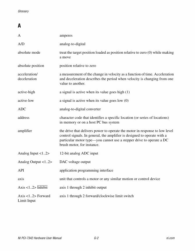
Glossary
NI PCI-7342 Hardware User Manual G-2 ni.com
A
A amperes
A/D analog-to-digital
absolute mode treat the target position loaded as position relative to zero (0) while making a move
absolute position position relative to zero
acceleration/deceleration
a measurement of the change in velocity as a function of time. Acceleration and deceleration describes the period when velocity is changing from one value to another.
active-high a signal is active when its value goes high (1)
active-low a signal is active when its value goes low (0)
ADC analog-to-digital converter
address character code that identifies a specific location (or series of locations) in memory or on a host PC bus system
amplifier the drive that delivers power to operate the motor in response to low level control signals. In general, the amplifier is designed to operate with a particular motor type—you cannot use a stepper drive to operate a DC brush motor, for instance.
Analog Input <1..2> 12-bit analog ADC input
Analog Output <1..2> DAC voltage output
API application programming interface
axis unit that controls a motor or any similar motion or control device
Axis <1..2> Inhibit axis 1 through 2 inhibit output
Axis <1..2> Forward Limit Input
axis 1 through 2 forward/clockwise limit switch
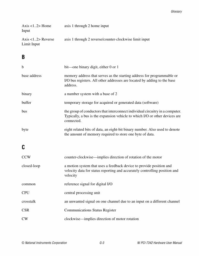
Glossary
© National Instruments Corporation G-3 NI PCI-7342 Hardware User Manual
Axis <1..2> Home Input
axis 1 through 2 home input
Axis <1..2> Reverse Limit Input
axis 1 through 2 reverse/counter-clockwise limit input
B
b bit—one binary digit, either 0 or 1
base address memory address that serves as the starting address for programmable or I/O bus registers. All other addresses are located by adding to the base address.
binary a number system with a base of 2
buffer temporary storage for acquired or generated data (software)
bus the group of conductors that interconnect individual circuitry in a computer. Typically, a bus is the expansion vehicle to which I/O or other devices are connected.
byte eight related bits of data, an eight-bit binary number. Also used to denote the amount of memory required to store one byte of data.
C
CCW counter-clockwise—implies direction of rotation of the motor
closed-loop a motion system that uses a feedback device to provide position and velocity data for status reporting and accurately controlling position and velocity
common reference signal for digital I/O
CPU central processing unit
crosstalk an unwanted signal on one channel due to an input on a different channel
CSR Communications Status Register
CW clockwise—implies direction of motor rotation
Glossary
NI PCI-7342 Hardware User Manual G-4 ni.com
D
DAC Digital-to-Analog Converter
DC direct current
dedicated assigned to a particular function
DGND digital ground signal
digital I/O port a group of digital input/output signals
DIP dual inline package
DLL dynamic link library—provides the API for the motion control boards
drivers software that communicates commands to control a specific motion control board
DSP Digital Signal Processor
E
encoder device that translates mechanical motion into electrical signals; used for monitoring position or velocity in a closed-loop system
encoder resolution the number of encoder lines between consecutive encoder indexes (marker or Z-bit). If the encoder does not have an index output, the encoder resolution can be referred to as lines per revolution.
F
f farad
FIFO First-In, First-Out
filtering a type of signal conditioning that filters unwanted signals from the signal being measured
filter parameters indicates the control loop parameter gains (PID gains) for a given axis
flash ROM a type of electrically reprogrammable read-only memory
Glossary
© National Instruments Corporation G-5 NI PCI-7342 Hardware User Manual
following error trip point
the difference between the instantaneous commanded trajectory position and the feedback position
FPGA Field Programmable Gate Array
freewheel the condition of a motor when power is de-energized and the motor shaft is free to turn with only frictional forces to impede it
full-step full-step mode of a stepper motor—for a two phase motor this is done by energizing both windings or phases simultaneously
G
Gnd ground
GND ground
H
half-step mode of a stepper motor—for a two phase motor this is done by alternately energizing two windings and then only one. In half step mode, alternate steps are strong and weak but there is significant improvement in low-speed smoothness over the full-step mode.
hex hexadecimal
home switch (input) A physical position determined by the mechanical system or designer as the reference location for system initialization. Frequently, the home position is also regarded as the zero position in an absolute position frame of reference.
host computer computer into which the motion control board is plugged
I
I/O input/output—the transfer of data to and from a computer system involving communications channels, operator interface devices, and/or motion control interfaces
ID identification
in. inches
Glossary
NI PCI-7342 Hardware User Manual G-6 ni.com
index marker between consecutive encoder revolutions
inverting the polarity of a switch (limit switch, home switch, and so on) in active state. If these switches are active-low they are said to have inverting polarity.
IRQ interrupt request
K
k kilo—the standard metric prefix for 1,000, or 103, used with units of measure such as volts, hertz, and meters
K kilo—the prefix for 1,024, or 210, used with B in quantifying data or computer memory
L
LIFO Last-In, First-Out
limit switch/end-of-travel position (input)
sensors that alert the control electronics that physical end of travel is being approached and that the motion should stop
M
m meters
MCS Move Complete Status
microstep The proportional control of energy in the coils of a Stepper Motor that allow the motor to move to or stop at locations other than the fixed magnetic/mechanical pole positions determined by the motor specifications. This capability facilitates the subdivision of full mechanical steps on a stepper motor into finer microstep locations that greatly smooth motor running operation and increase the resolution or number of discrete positions that a stepper motor can attain in each revolution.
modulo position treat the position as within the range of total quadrature counts per revolution for an axis
Glossary
© National Instruments Corporation G-7 NI PCI-7342 Hardware User Manual
N
noise an undesirable electrical signal—noise comes from external sources such as the AC power line, motors, generators, transformers, fluorescent lights, soldering irons, CRT displays, computers, electrical storms, welders, radio transmitters, and internal sources such as semiconductors, resistors, and capacitors. Noise corrupts signals you are trying to send or receive.
noninverting the polarity of a switch (limit switch, home switch, etc.) in active state. If these switches are active-high, they are said to have non-inverting polarity.
O
open-loop refers to a motion control system where no external sensors (feedback devices) are used to provide position or velocity correction signals
open collector refers to a transistor current that can only sink current, allowing multiple devices to communicate bidirectionally on a single line
P
PCI Peripheral Component Interconnect—a high-performance expansion bus architecture originally developed by Intel to replace ISA and EISA. It is achieving widespread acceptance as a standard for PCs and workstations; it offers a theoretical maximum transfer rate of 132 MB/s.
PID proportional-integral-derivative control loop
PIVff proportional-integral-velocity feedforward
port (1) a communications connection on a computer or a remote controller (2) a digital port, consisting eight lines of digital input and/or output
position breakpoint position breakpoint for an encoder can be set in absolute or relative quadrature counts. When the encoder reaches a position breakpoint, the associated breakpoint output immediately transitions.
power cycling turning the host computer off and then back on, which causes a reset of the motion control board
Glossary
NI PCI-7342 Hardware User Manual G-8 ni.com
PWM Pulse Width Modulation—a method of controlling the average current in a motor phase winding by varying the on-time (duty cycle) of transistor switches
PXI PCI eXtensions for Instrumentation
Q
quadrature counts the encoder line resolution times four
R
RAM random-access memory
relative breakpoint sets the position breakpoint for an encoder in relative quadrature counts
relative position destination or target position for motion specified with respect to the current location regardless of its value
relative position mode position relative to current position
ribbon cable a flat cable in which the conductors are side by side
RPM revolutions per minute—units for velocity
RPSPS or RPS/S revolutions per second squared—units for acceleration and deceleration
RTR Ready to Receive
S
s seconds
servo specifies an axis that controls a servo motor
stepper specifies an axis that controls a stepper motor
stepper <1..2> Dir (CCW)
direction output or counter-clockwise direction control
stepper <1..2> Step (CW)
stepper pulse output or clockwise direction control
Glossary
© National Instruments Corporation G-9 NI PCI-7342 Hardware User Manual
T
toggle changing state from high to low, back to high, and so on
torque force tending to produce rotation
trapezoidal profile a typical motion trajectory, where a motor accelerates up to the programmed velocity using the programmed acceleration, traverses at the programmed velocity, then decelerates at the programmed acceleration to the target position
trigger any event that causes or starts some form of data capture
TTL transistor-transistor logic
V
V volts
VCC positive voltage supply
velocity mode move the axis continuously at the specified velocity
W
watchdog a timer task that shuts down (resets) the motion control board if any serious error occurs
word the standard number of bits that a processor or memory manipulates at one time, typically 8-, 16-, or 32-bit
© National Instruments Corporation I-1 NI PCI-7342 Hardware User Manual
Index
Numbers+5 V signal. See Host +5 V signal
Aanalog feedback, 4-2Analog Input <1..2> signal
analog input voltage ranges (table), 5-14description (table), 5-4internal ADC channels (table), 5-13purpose and use, 5-13 to 5-14
Analog Input Ground signaldescription (table), 5-4purpose and use, 5-14
analog inputssignal descriptions, 5-13 to 5-15wiring concerns, 5-15
Analog Output <1..2> signaldescription (table), 5-4purpose and use, 5-5
Analog Output Ground signaldescription (table), 5-4purpose and use, 5-5
Analog Reference signaldescription (table), 5-4purpose and use, 5-14
axes, 4-3 to 4-4See also servo axes; stepper axes
Axis<1..2> Dir (CCW) signalcompatibility with third-party drives, 5-5description (table), 5-4purpose and use, 5-5
Axis<1..2> Encoder Index signaldescription (table), 5-4purpose and use, 5-9 to 5-10
Axis<1..2> Encoder Phase A signaldescription (table), 5-4purpose and use, 5-8 to 5-9
Axis<1..2> Encoder Phase B signaldescription (table), 5-4purpose and use, 5-8 to 5-9
Axis<1..2> Forward Limit Switch signaldescription (table), 5-4purpose and use, 5-6 to 5-7
Axis<1..2> Home Switch signaldescription (table), 5-4purpose and use, 5-6 to 5-7
Axis<1..2> Inhibit signaldescription (table), 5-4purpose and use, 5-6
Axis<1..2> Reverse Limit Switch signaldescription (table), 5-4purpose and use, 5-6 to 5-7
Axis<1..2> Step (CW) signalcompatibility with third-party drives, 5-5description (table), 5-4purpose and use, 5-5
Bbreakpoint outputs
output circuit (figure), 5-13wiring concerns, 5-12
Breakpoint<1..2> signaldescription, 5-4purpose and use, 5-12
Index
NI PCI-7342 Hardware User Manual I-2 ni.com
Ccable connectors
50-pin servo connector pin assignments (figure), B-2
50-pin stepper connector pin assignments (figure), B-1
communications, host, 4-5configuration of controller, 2-1connectors. See cable connectors; digital I/O
connector; motion I/O connector; RTSI connector
controller configuration, 2-1conventions used in manual, ix
DDigital Ground signal (table), 5-4digital I/O connector, 5-16 to 5-17
68-pin connector pin assignments (figure), 5-16
connection to PCI-7342 controller (figure), 5-1
description, 5-17overview, 3-2PWM features, 5-17specifications, A-6
documentationconventions used in manual, ixrelated documentation, x
dual processor architecture, 4-1 to 4-3
Eelectromagnetic compatibility
specifications, A-8embedded real-time operating system
(RTOS), 4-2encoder signals, 5-8 to 5-13
Axis<1..2> Encoder Index, 5-4, 5-9 to 5-10
Axis<1..2> Encoder Phase A, 5-4, 5-8 to 5-9
Axis<1..2> Encoder Phase B, 5-4, 5-8 to 5-9
input circuit, 5-11wiring concerns, 5-10
environment specifications, A-7equipment, optional, 1-4
Fflash memory, 4-3FPGA configuration programs, 4-3functional overview, 4-1 to 4-5
analog feedback, 4-2axes, 4-3 to 4-4dual processor architecture, 4-1 to 4-3embedded real-time operating system
(RTOS), 4-2flash memory, 4-3host communications, 4-5motion resources, 4-4 to 4-5trajectory generators, 4-2
Hhardware, 3-1 to 3-2
See also functional overviewinstallation
procedural steps, 2-4 to 2-5safety information, 2-2 to 2-3unpacking, 2-1 to 2-2
overview, 1-1parts locator diagram, 3-1user connectors, 3-2
Host +5 V signaldescription (table), 5-4purpose and use, 5-15
host communications, 4-5
Index
© National Instruments Corporation I-3 NI PCI-7342 Hardware User Manual
Iinstallation
hardware, 2-4 to 2-5safety information, 2-2 to 2-4software, 2-1unpacking, 2-1 to 2-2
LLabVIEW software, 1-3LabWindows/CVI software, 1-4limit and home inputs, 5-6 to 5-7
Axis<1..2> Forward Limit Switch, 5-4, 5-6 to 5-7
Axis<1..2> Home Switch, 5-4, 5-6 to 5-7Axis<1..2> Reverse Limit Switch, 5-4,
5-6 to 5-7input circuit, 5-7 to 5-8wiring concerns, 5-7
Mmanual. See documentationmaximum working voltage specifications, A-7memory, nonvolatile, 4-3motion axis signals, 5-5 to to 5-6
Analog Output <1..2>, 5-4, 5-5Analog Output Ground, 5-4, 5-5Axis<1..2> Dir (CCW), 5-4, 5-5Axis<1..2> Inhibit, 5-4, 5-6Axis<1..2> Step (CW), 5-4, 5-5
motion I/O connector, 5-2 to 5-1568-pin connector pin assignments
(figure), 5-3analog inputs, 5-13 to 5-15
signal descriptions, 5-13 to 5-14wiring concerns, 5-15
connector on PCI-7342 controller (figure), 5-1
encoder signals, 5-8 to 5-13input circuit, 5-11
signal descriptions, 5-8 to 5-10wiring concerns, 5-10
features, 5-2limit and home inputs, 5-6 to 5-8
input circuit, 5-7 to 5-8signal descriptions, 5-6 to 5-7wiring concerns, 5-7
motion axis signals, 5-5 to 5-6other connections, 5-15overview, 3-2signal connections (table), 5-4specifications, A-3 to A-5trigger inputs, shutdown input, and
breakpoint outputs, 5-11 to 5-13circuits (figures), 5-12 to 5-13signal descriptions, 5-11 to 5-12wiring concerns, 5-12
motion resources, 4-4 to 4-5
NNational Instruments application software,
1-3 to 1-4NI PCI-7342
features, 1-2hardware, 1-1requirements for getting started, 1-3RTSI, 1-1 to 1-2servo and stepper fundamentals,
1-2 to 1-3software programming choices, 1-3 to 1-4
NI-Motion software, 1-4
Ooptional equipment, 1-4
Pparts locator diagram, 3-1physical specifications, A-7
Index
NI PCI-7342 Hardware User Manual I-4 ni.com
power requirement specifications, A-6pulse width modulation outputs, digital I/O
connector, 5-17PWM features, digital I/O connector, 5-17
Rrequirements for getting started, 1-3RTOS (embedded real-time operating
system), 4-2RTSI connector
Breakpoint across RTSI (figure), 5-18overview, 1-1 to 1-2, 3-2pins available for user signals (note), 1-2signal considerations, 5-17 to 5-18specifications, A-6
Ssafety
safety information, 2-2 to 2-4specifications, A-8system safety specifications, A-3
servo axesaxis resources (figure), 4-4connector pin assignments (figure), B-2performance specifications, A-1 to A-2servo and stepper fundamentals,
1-2 to 1-3shutdown input
input circuit (figure), 5-13wiring concerns, 5-12
Shutdown signaldescription (table), 5-4purpose and use, 5-11 to 5-12
signal connections. See digital I/O connector; motion I/O connector; RTSI connector
software installation, 2-1software programming choices, 1-3 to 1-4specifications
digital I/O, A-6
electromagnetic compatibility, A-8environment, A-7maximum working voltage, A-7motion I/O, A-3 to A-5physical, A-7power requirements (max), A-6RTSI trigger lines, A-6servo performance, A-1 to A-2stepper performance, A-2 to A-3system safety, A-3
stepper axesaxis resources (figure), 4-4connector pin assignments (figure), B-1performance specifications, A-2 to A-3stepper and servo fundamentals,
1-2 to 1-3system safety specifications, A-3
Ttechnical support resources, C-1trajectory generators, 4-2trigger inputs, 5-11 to 5-13
trigger input circuit (figure), 5-12wiring concerns, 5-12
Trigger<1..2> signaldescription (table), 5-4purpose and use, 5-11
Uunpacking NI PCI-7342, 2-1 to 2-2user connectors. See digital I/O connector;
motion I/O connector; RTSI connector
Vvoltage specifications, maximum
working, A-7

Index
© National Instruments Corporation I-5 NI PCI-7342 Hardware User Manual
Wwiring concerns
analog inputs, 5-15breakpoint outputs, 5-12encoder signals, 5-10limit and home inputs, 5-7shutdown input, 5-12trigger inputs, 5-12