Embed Size (px)
Citation preview

Slide 1 Changes for 2017
NFPA 25 Handbook Supplement 8 contains a table highlighting the significant technical changes to NFPA 25 for the 2017 edition, along with a brief comment regarding the reason for the change. For a complete record of all changes, along with the full committee statements for both editorial and technical changes, consult the NFPA 25 First Draft Report and Second Draft Report for the Annual 2016 Revision Cycle. These reports can be downloaded from the NFPA 25 document page at www.nfpa.org
Slide 2 NFPA 25: 2017
Ch. 1: Administration
Ch. 2: Referenced Publications
Ch. 3: Definitions
Ch. 4: General Requirements
Ch. 5: Sprinkler Systems
Ch. 6: Standpipe and Hose Systems
Ch. 7: Private Fire Service Mains
Ch. 8: Fire Pumps
Ch. 9: Water Storage Tanks
Ch. 10: Water Spray Fixed Systems
2
Ch. 10: Water Spray Fixed Systems
Ch. 11: Foam-Water Sprinkler Systems
Ch. 12: Water Mist Systems
Ch. 13: Valves, Valve Components, and Trim
Ch. 14: Internal Piping Condition and Obstruction Investigation
Ch. 15: Impairments
Ch. 16: Special Requirements from Other NFPA Documents
Annex A-F
Slide 3 NFPA 13 D Systems
1.1.5 3
Unless required by Chapter 16, this standard shall
not apply to sprinkler systems designed, installed,
and maintained in accordance with NFPA 13D.
This text was revised address the fact that the standard does not typically apply to NFPA 13D systems, however Chapter 16 was added last cycle to specifically handle these systems in very specific occupancies.
Slide 4 Ch. 3: Definitions
3.2.25* 4
Maintenance.
In water-based fire protection systems, work
performed to keep equipment operable.
Reference to ‘repairs’ has been removed
from the definition of maintenance.
The term maintenance is broadly defined as including repair, nowhere in the standard is maintenance used in such a fashion. Repair is expressly identified as an individual action throughout the standard.
Slide 5 3.6.2 Fire Pump Definitions
3.6.2.3*5
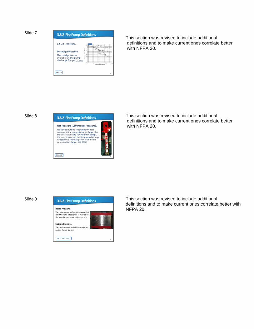
No Flow (Churn, Shutoff).
The condition of zero flow when the fire pump is running but the only water passing through the pump is a small flow that is discharged through the pump circulation relief valve or supplies the cooling for a diesel engine driver. [20, 2016]
This section was revised to include additional definitions and to make current ones correlate better with NFPA 20.
Slide 6 3.6.2 Fire Pump Definitions
3.6.2.4*6
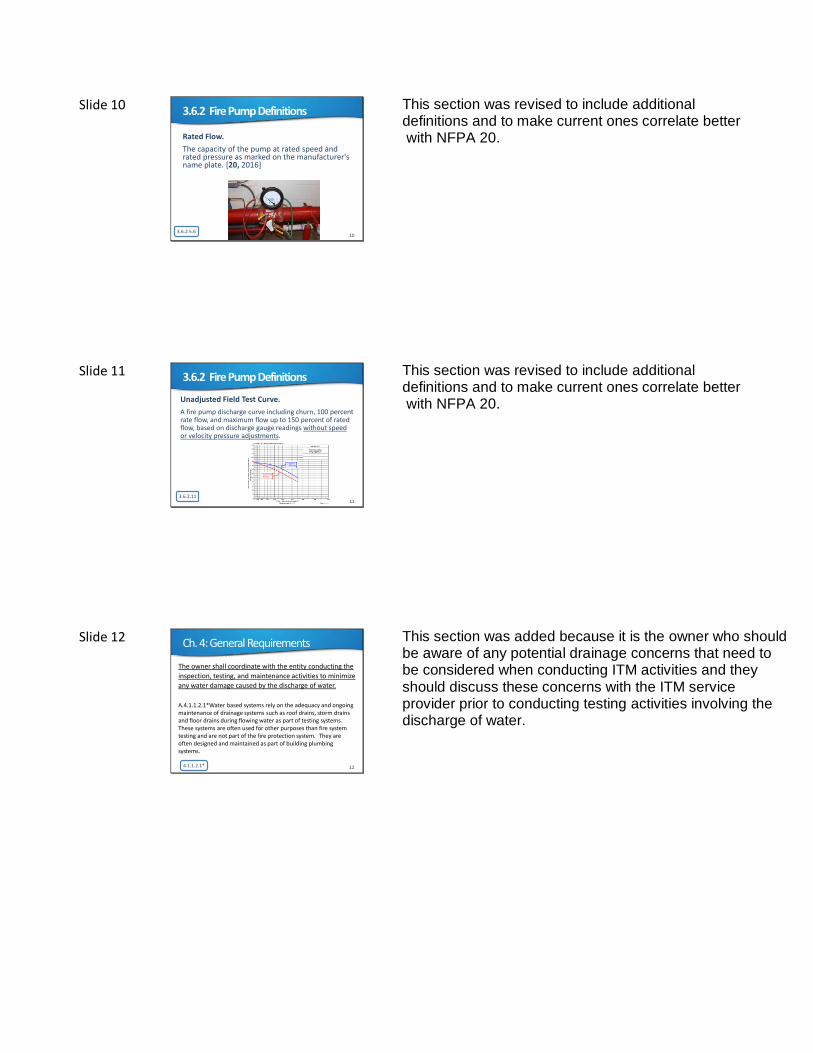
Peak Load.
As pertains to acceptance testing in this standard is the maximum power required to drive the pump at any flow rate up to 150 percent of rated capacity (flow). [20, 2016]
This section was revised to include additional definitions and to make current ones correlate better with NFPA 20.
Slide 7 3.6.2 Fire Pump Definitions
3.6.2.5.17
3.6.2.5 Pressure.
Discharge Pressure.
The total pressure available at the pump discharge flange. [20, 2016]
No Flow
This section was revised to include additional definitions and to make current ones correlate better with NFPA 20.
Slide 8 3.6.2 Fire Pump Definitions
3.6.2.5.2*8
Net Pressure (Differential Pressure).
For vertical turbine fire pumps the total pressure at the pump discharge flange plus the total suction lift. For other fire pumps, the total pressure at the fire pump discharge flange minus the total pressure at the fire pump suction flange. [20, 2016]
This section was revised to include additional definitions and to make current ones correlate better with NFPA 20.
Slide 9 3.6.2 Fire Pump Definitions
3.6.2.5.3 & 3.6.2.5.49
Rated Pressure.
The net pressure (differential pressure) at
rated flow and rated speed as marked on
the manufacturer’s nameplate. [20, 2016]
Suction Pressure.
The total pressure available at the pump
suction flange. [20, 2016]
This section was revised to include additional definitions and to make current ones correlate better with NFPA 20.
Slide 10 3.6.2 Fire Pump Definitions
3.6.2.5.610
Rated Flow.
The capacity of the pump at rated speed and rated pressure as marked on the manufacturer's name plate. [20, 2016]
This section was revised to include additional definitions and to make current ones correlate better with NFPA 20.
Slide 11 3.6.2 Fire Pump Definitions
3.6.2.1111
Unadjusted Field Test Curve.
A fire pump discharge curve including churn, 100 percent rate flow, and maximum flow up to 150 percent of rated flow, based on discharge gauge readings without speed or velocity pressure adjustments.
This section was revised to include additional definitions and to make current ones correlate better with NFPA 20.
Slide 12 Ch. 4: General Requirements
4.1.1.2.1* 12
The owner shall coordinate with the entity conducting the
inspection, testing, and maintenance activities to minimize
any water damage caused by the discharge of water.
A.4.1.1.2.1*Water based systems rely on the adequacy and ongoing maintenance of drainage systems such as roof drains, storm drains and floor drains during flowing water as part of testing systems. These systems are often used for other purposes than fire system testing and are not part of the fire protection system. They are often designed and maintained as part of building plumbing systems.
This section was added because it is the owner who should be aware of any potential drainage concerns that need to be considered when conducting ITM activities and they should discuss these concerns with the ITM service provider prior to conducting testing activities involving the discharge of water.
Slide 13 Ch. 4: General Requirements
4.1.5.1* 13
The property owner or designated representative
shall correct or repair deficiencies or impairments
Section has been revised to be more clear and require corrections any time a deficiency or impairment is identified as opposed to the assumption that it applies only when found during an inspection.
Slide 14 Ch. 4: General Requirements
4.1.6.2*14
The evaluation shall consider factors that include, but are not limited to, the
following:
(1) Occupancy changes such as converting office or production space into warehousing
(2) Process or material changes such as metal stamping to molded plastics
(3) Building revisions such as relocated walls, added mezzanines, and ceilings added
below sprinklers
(4) Removal of heating systems in spaces with piping subject to freezing
(5) Changes to the storage method, arrangement, height or commodities
(6) Changes in water supplies
Items (5) and (6) were added to the list of factors that should be included in the evaluation required by 4.1.6. Both changes to storage and water supplies can have major implications on the adequacy of a fire protection system.
Slide 15 Ch. 4: General Requirements
4.1.10 15
Antifreeze Information Sign.
An antifreeze information sign shall be placed on the antifreeze system main valve, which indicates the manufacture type and brand of the antifreeze solution, the concentration by volume of the antifreeze solution used, and the volume of the antifreeze solution used in the system.
This new requirement ensures that details of the antifreeze solution be posted at the antifreeze loop main valve, so that all parties can be aware of what is on hand within a system.
Slide 16 Ch. 4: General Requirements
16
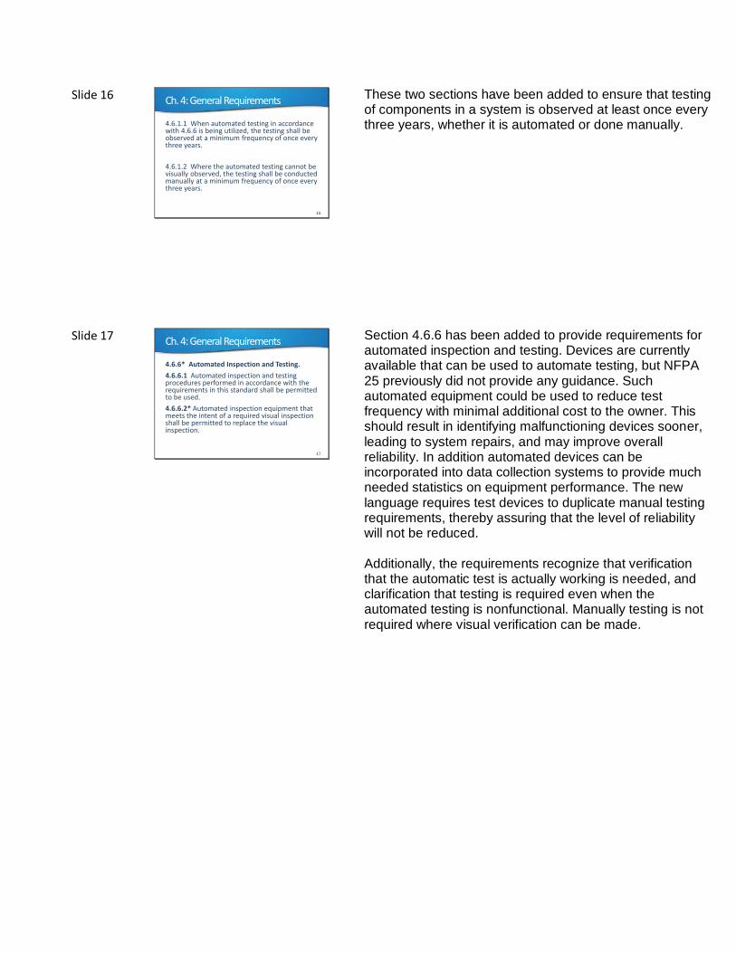
4.6.1.1 When automated testing in accordance with 4.6.6 is being utilized, the testing shall be observed at a minimum frequency of once every three years.
4.6.1.2 Where the automated testing cannot be visually observed, the testing shall be conducted manually at a minimum frequency of once every three years.
These two sections have been added to ensure that testing of components in a system is observed at least once every three years, whether it is automated or done manually.
Slide 17 Ch. 4: General Requirements
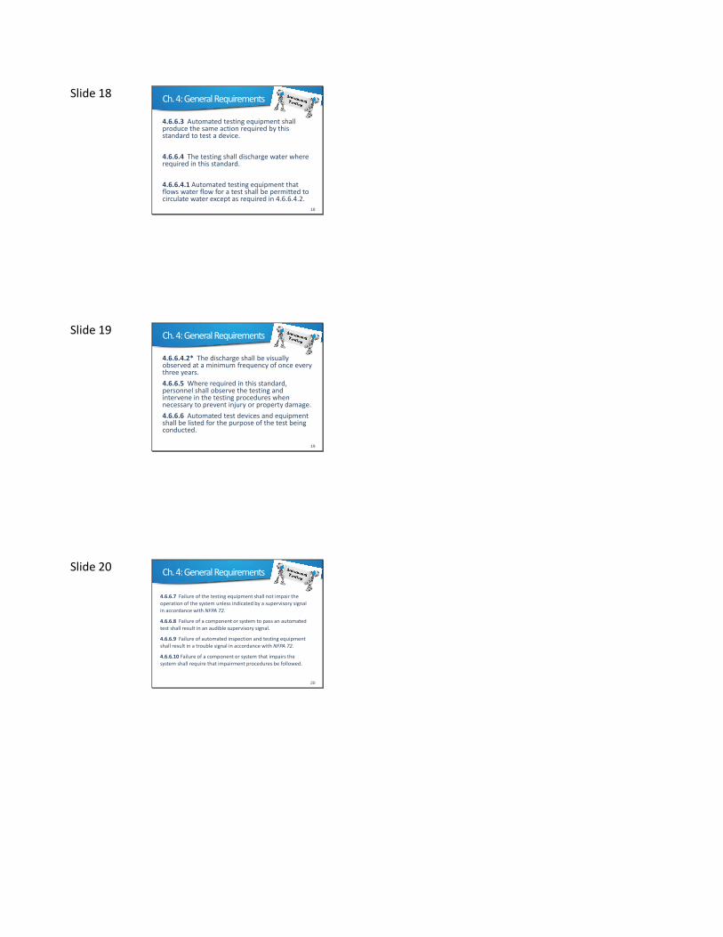
4.6.6* Automated Inspection and Testing.
4.6.6.1 Automated inspection and testing procedures performed in accordance with the requirements in this standard shall be permitted to be used.
4.6.6.2* Automated inspection equipment that meets the intent of a required visual inspection shall be permitted to replace the visual inspection.
17
Section 4.6.6 has been added to provide requirements for automated inspection and testing. Devices are currently available that can be used to automate testing, but NFPA 25 previously did not provide any guidance. Such automated equipment could be used to reduce test frequency with minimal additional cost to the owner. This should result in identifying malfunctioning devices sooner, leading to system repairs, and may improve overall reliability. In addition automated devices can be incorporated into data collection systems to provide much needed statistics on equipment performance. The new language requires test devices to duplicate manual testing requirements, thereby assuring that the level of reliability will not be reduced.
Additionally, the requirements recognize that verification that the automatic test is actually working is needed, and clarification that testing is required even when the automated testing is nonfunctional. Manually testing is not required where visual verification can be made.
Slide 18 Ch. 4: General Requirements
18
4.6.6.3 Automated testing equipment shall produce the same action required by this standard to test a device.
4.6.6.4 The testing shall discharge water where required in this standard.
4.6.6.4.1 Automated testing equipment that flows water flow for a test shall be permitted to circulate water except as required in 4.6.6.4.2.
Slide 19 Ch. 4: General Requirements
19
4.6.6.4.2* The discharge shall be visually observed at a minimum frequency of once every three years.
4.6.6.5 Where required in this standard, personnel shall observe the testing and intervene in the testing procedures when necessary to prevent injury or property damage.
4.6.6.6 Automated test devices and equipment shall be listed for the purpose of the test being conducted.
Slide 20 Ch. 4: General Requirements
20
4.6.6.7 Failure of the testing equipment shall not impair the
operation of the system unless indicated by a supervisory signal
in accordance with NFPA 72.
4.6.6.8 Failure of a component or system to pass an automated test shall result in an audible supervisory signal.
4.6.6.9 Failure of automated inspection and testing equipment shall result in a trouble signal in accordance with NFPA 72.
4.6.6.10 Failure of a component or system that impairs the
system shall require that impairment procedures be followed.
Slide 21 Ch. 4: General Requirements
21
4.6.6.11 The testing frequencies of this standard shall be maintained regardless of the functionality of the automated testing equipment.
4.6.6.12 A record of all inspections and testing shall be maintained in accordance with 4.3.2.
A.4.6.6 Some devices, such as waterflow alarm devices, can be tested automatically. Some things to consider include the following:
1. Not all tests required by NFPA 25 are suitable for automatic testing.
2. Periodic visual inspection, including the use of video, should be performed
Slide 22 Ch. 4: General Requirements
22
A.4.6.6.2 Transducers, temperature sensors, automatic- and remotely-operated valves, including motorized valves, and solenoids are examples of some of the equipment that could be used in an automated inspection. The list of items above is a partial list and should not be considered an exclusive list of equipment and methodologies.
A.4.6.6.4.2 The visual observation should be coordinated with the automatic testing. Appropriate remote visual observation might satisfy this requirement.
Slide 23 Ch. 4: General Requirements
23
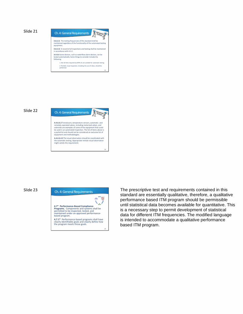
4.7* Performance-Based Compliance Programs. Components and systems shall be permitted to be inspected, tested, and maintained under an approved performance-based program.
4.7.1* Performance-based programs shall have clearly identifiable goals and clearly define how the program meets those goals.
Report & Analysis, Establish
Goals
AHJ Approval
Data Collection
The prescriptive test and requirements contained in this standard are essentially qualitative, therefore, a qualitative performance based ITM program should be permissible until statistical data becomes available for quantitative. This is a necessary step to permit development of statistical data for different ITM frequencies. The modified language is intended to accommodate a qualitative performance based ITM program.
Slide 24 Ch. 4: General Requirements
24
4.7.2 Compliance with an approved performance-based program shall be deemed as compliance with this standard.
4.7.3 The goals and goal achievement obtained with the approved performance-based program shall be reviewed a minimum of every three years and ITM frequencies adjusted to reflect current conditions and the historical record.
4.7.4 The historical record shall be available for review by the authority having jurisdiction.
Slide 25 Ch. 4: General Requirements
25
4.8 Maintenance.
Maintenance shall be performed to keep the system equipment operable.
“An ounce of
prevention… is
worth a pound
of cure”
Reference to ‘repairs’ has been removed from this requirement.
Slide 26 Table 5.1.1.2
26
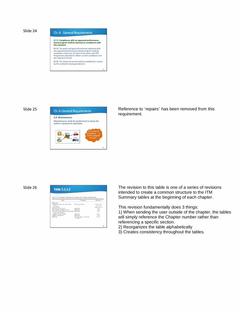
The revision to this table is one of a series of revisions intended to create a common structure to the ITM Summary tables at the beginning of each chapter. This revision fundamentally does 3 things: 1) When sending the user outside of the chapter, the tables will simply reference the Chapter number rather than referencing a specific section. 2) Reorganizes the table alphabetically 3) Creates consistency throughout the tables.
Slide 27 Ch. 5: Sprinkler Systems
27
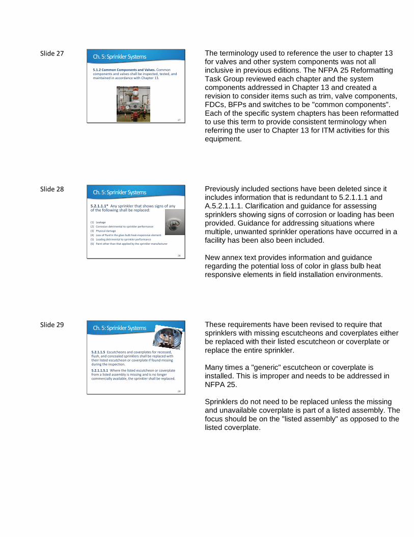
5.1.2 Common Components and Valves. Common components and valves shall be inspected, tested, and maintained in accordance with Chapter 13.
The terminology used to reference the user to chapter 13 for valves and other system components was not all inclusive in previous editions. The NFPA 25 Reformatting Task Group reviewed each chapter and the system components addressed in Chapter 13 and created a revision to consider items such as trim, valve components, FDCs, BFPs and switches to be "common components". Each of the specific system chapters has been reformatted to use this term to provide consistent terminology when referring the user to Chapter 13 for ITM activities for this equipment.
Slide 28 Ch. 5: Sprinkler Systems
28
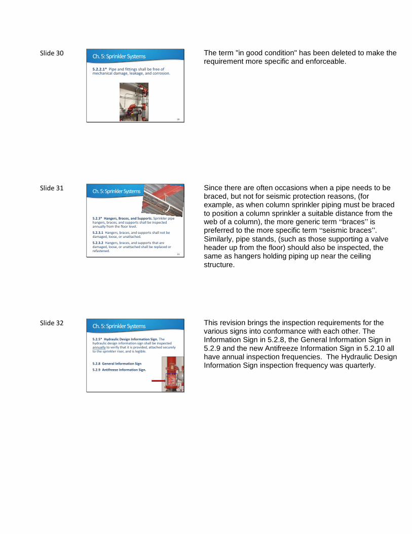
5.2.1.1.1* Any sprinkler that shows signs of any of the following shall be replaced:
(1) Leakage
(2) Corrosion detrimental to sprinkler performance
(3) Physical damage
(4) Loss of fluid in the glass bulb heat-responsive element
(5) Loading detrimental to sprinkler performance
(6) Paint other than that applied by the sprinkler manufacturer
Previously included sections have been deleted since it includes information that is redundant to 5.2.1.1.1 and A.5.2.1.1.1. Clarification and guidance for assessing sprinklers showing signs of corrosion or loading has been provided. Guidance for addressing situations where multiple, unwanted sprinkler operations have occurred in a facility has been also been included. New annex text provides information and guidance regarding the potential loss of color in glass bulb heat responsive elements in field installation environments.
Slide 29 Ch. 5: Sprinkler Systems
29
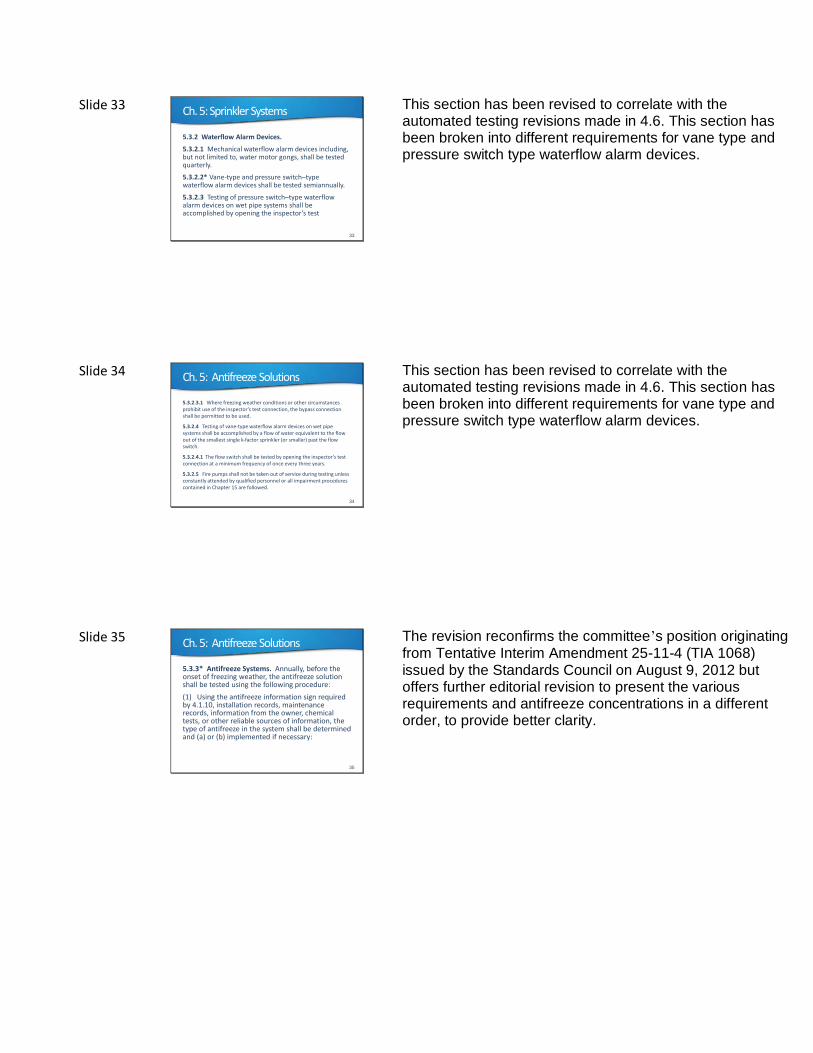
5.2.1.1.5 Escutcheons and coverplates for recessed, flush, and concealed sprinklers shall be replaced with their listed escutcheon or coverplate if found missing during the inspection.
5.2.1.1.5.1 Where the listed escutcheon or coverplatefrom a listed assembly is missing and is no longer commercially available, the sprinkler shall be replaced.
These requirements have been revised to require that sprinklers with missing escutcheons and coverplates either be replaced with their listed escutcheon or coverplate or replace the entire sprinkler. Many times a "generic" escutcheon or coverplate is installed. This is improper and needs to be addressed in NFPA 25. Sprinklers do not need to be replaced unless the missing and unavailable coverplate is part of a listed assembly. The focus should be on the "listed assembly" as opposed to the listed coverplate.
Slide 30 Ch. 5: Sprinkler Systems
30
5.2.2.1* Pipe and fittings shall be free of mechanical damage, leakage, and corrosion.
The term "in good condition" has been deleted to make the requirement more specific and enforceable.
Slide 31 Ch. 5: Sprinkler Systems
31
5.2.3* Hangers, Braces, and Supports. Sprinkler pipe hangers, braces, and supports shall be inspected annually from the floor level.
5.2.3.1 Hangers, braces, and supports shall not be damaged, loose, or unattached.
5.2.3.2 Hangers, braces, and supports that are damaged, loose, or unattached shall be replaced or refastened.
Since there are often occasions when a pipe needs to be braced, but not for seismic protection reasons, (for example, as when column sprinkler piping must be braced to position a column sprinkler a suitable distance from the web of a column), the more generic term “braces” is preferred to the more specific term “seismic braces”.
Similarly, pipe stands, (such as those supporting a valve header up from the floor) should also be inspected, the same as hangers holding piping up near the ceiling structure.
Slide 32 Ch. 5: Sprinkler Systems
32
5.2.5* Hydraulic Design Information Sign. The hydraulic design information sign shall be inspected annually to verify that it is provided, attached securely to the sprinkler riser, and is legible.
5.2.8 General Information Sign
5.2.9 Antifreeze Information Sign.
This revision brings the inspection requirements for the various signs into conformance with each other. The Information Sign in 5.2.8, the General Information Sign in 5.2.9 and the new Antifreeze Information Sign in 5.2.10 all have annual inspection frequencies. The Hydraulic Design Information Sign inspection frequency was quarterly.
Slide 33 Ch. 5: Sprinkler Systems
33
5.3.2 Waterflow Alarm Devices.
5.3.2.1 Mechanical waterflow alarm devices including, but not limited to, water motor gongs, shall be tested quarterly.
5.3.2.2* Vane-type and pressure switch–type waterflow alarm devices shall be tested semiannually.
5.3.2.3 Testing of pressure switch–type waterflowalarm devices on wet pipe systems shall be accomplished by opening the inspector’s test
This section has been revised to correlate with the automated testing revisions made in 4.6. This section has been broken into different requirements for vane type and pressure switch type waterflow alarm devices.
Slide 34 Ch. 5: Antifreeze Solutions
34
5.3.2.3.1 Where freezing weather conditions or other circumstances prohibit use of the inspector’s test connection, the bypass connection shall be permitted to be used.
5.3.2.4 Testing of vane-type waterflow alarm devices on wet pipe systems shall be accomplished by a flow of water equivalent to the flow out of the smallest single k-factor sprinkler (or smaller) past the flow switch.
5.3.2.4.1 The flow switch shall be tested by opening the inspector’s test connection at a minimum frequency of once every three years.
5.3.2.5 Fire pumps shall not be taken out of service during testing unless constantly attended by qualified personnel or all impairment procedures contained in Chapter 15 are followed.
This section has been revised to correlate with the automated testing revisions made in 4.6. This section has been broken into different requirements for vane type and pressure switch type waterflow alarm devices.
Slide 35 Ch. 5: Antifreeze Solutions
35
5.3.3* Antifreeze Systems. Annually, before the onset of freezing weather, the antifreeze solution shall be tested using the following procedure:
(1) Using the antifreeze information sign required by 4.1.10, installation records, maintenance records, information from the owner, chemical tests, or other reliable sources of information, the type of antifreeze in the system shall be determined and (a) or (b) implemented if necessary:
The revision reconfirms the committee’s position originating from Tentative Interim Amendment 25-11-4 (TIA 1068) issued by the Standards Council on August 9, 2012 but offers further editorial revision to present the various requirements and antifreeze concentrations in a different order, to provide better clarity.
Slide 36 Ch. 5: Antifreeze Solutions
36
(a) If the antifreeze is found to be a type that is no longer permitted, the system shall be drained completely and the antifreeze replaced with an acceptable solution.
(b) If the type of antifreeze cannot be reliably determined, the system shall be drained completely and the antifreeze replaced with an acceptable solution in accordance with 5.3.3.4.
Slide 37 Ch. 5: Antifreeze Solutions
37
(2) If the antifreeze is not replaced in accordance with 5.3.3(1)(a) and 5.3.3(1)(b), test samples shall be taken at the top of each system and at the bottom of each system as follows:
(a) If the most remote portion of the system is not near the top or the bottom of the system, an additional sample shall be taken at the most remote portion.
(b) If the connection to the water supply piping is not near the top or the bottom of the system, an additional sample shall be taken at the connection to the water supply.
Slide 38 Ch. 5: Antifreeze Solutions
38
(3) The specific gravity of each solution shall be checked using a hydrometer with a suitable scale or a refractometer having a scale calibrated for the antifreeze solution.
(4) If any of the samples exhibits a concentration in excess of what is permitted by 5.3.3.4, the system shall be emptied and refilled with a new acceptable solution.
(5) If a concentration greater than what is currently permitted by 5.3.3.4 was necessary to keep the fluid from freezing, alternative methods for preventing the pipe from freezing shall be employed.
Slide 39 Ch. 5: Antifreeze Solutions
39
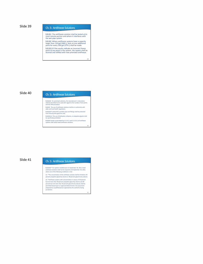
5.3.3.1 The antifreeze solution shall be tested at its most remote portion and where it interfaces with the wet pipe system.
5.3.3.2 Where antifreeze systems have a capacity larger than 150 gal (568 L), tests at one additional point for every 100 gal (379 L) shall be made.
5.3.3.2.1 If the results indicate an incorrect freeze point at any point in the system, the system shall be drained and refilled with new premixed antifreeze.
Slide 40 Ch. 5: Antifreeze Solutions
40
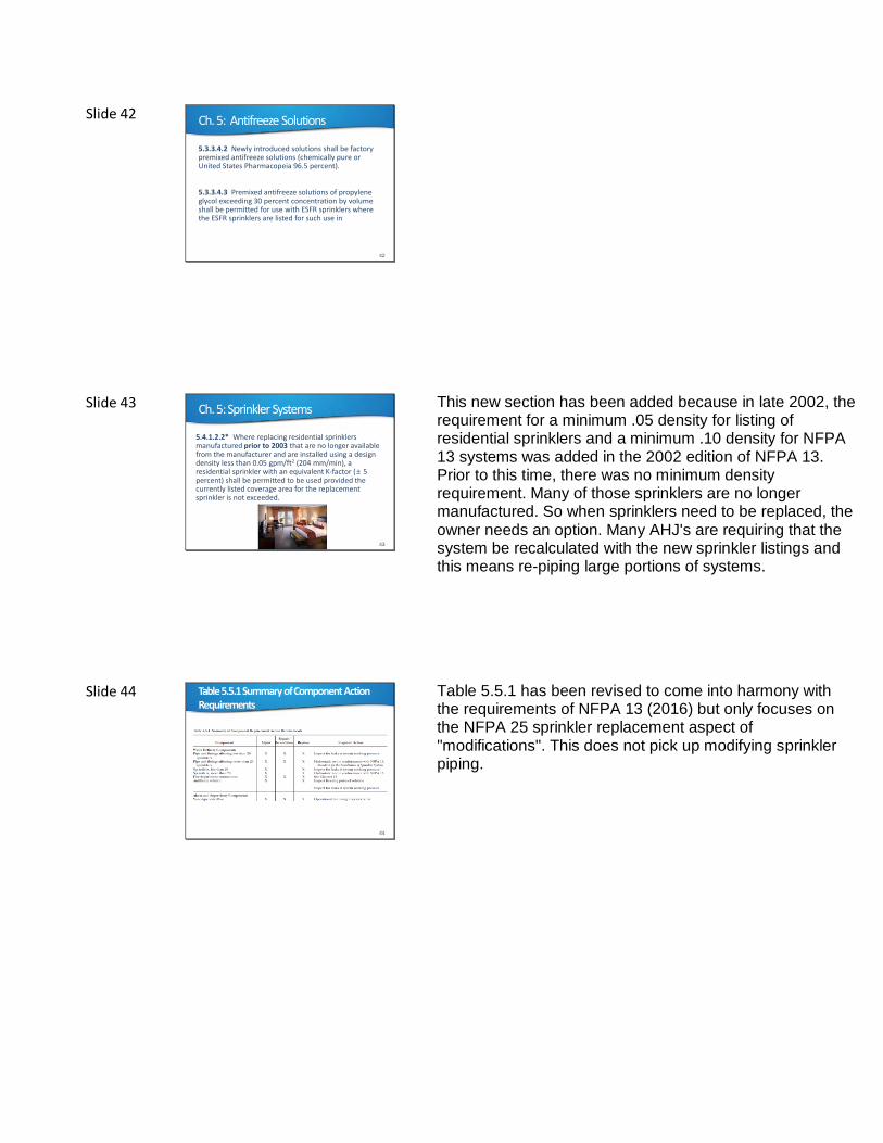
5.3.3.2.2 For premixed solutions, the manufacturer’s instructions shall be permitted to be used with regard to the number of test points and the refill procedure.
5.3.3.3 The use of antifreeze solutions shall be in conformity with state and local health regulations.
5.3.3.3.1* Listed CPVC sprinkler pipe and fittings shall be protected from freezing with glycerine only.
5.3.3.3.1.1 The use of diethylene, ethylene, or propylene glycols shall be specifically prohibited.
5.3.3.4 Except as permitted by 5.3.3.4.1 and 5.3.3.4.3, all antifreeze systems shall utilize listed antifreeze solutions.
Slide 41 Ch. 5: Antifreeze Solutions
41
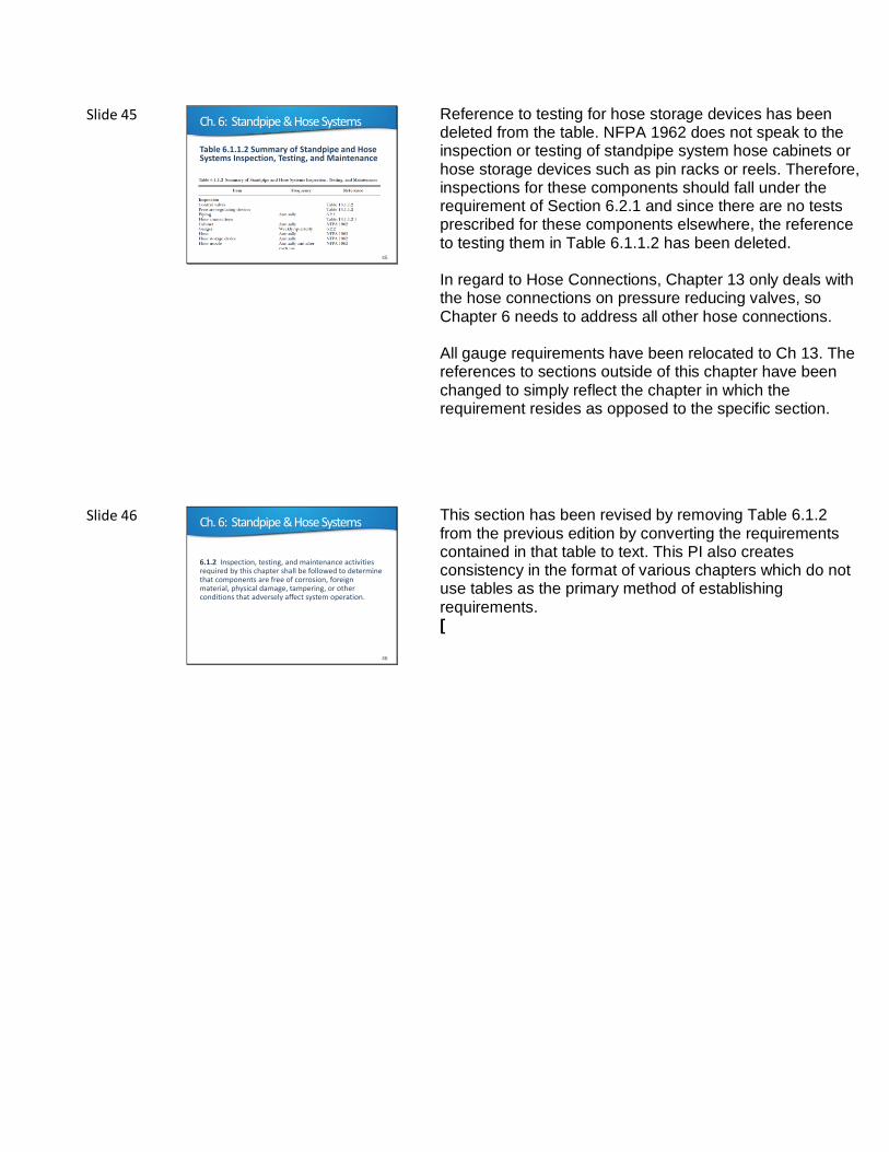
5.3.3.4.1* For systems installed prior to September 30, 2012, listed
antifreeze solutions shall not be required until September 30, 2022,
where one of the following conditions is met:
(1) *The concentration of the antifreeze solution shall be limited to 30
percent propylene glycol by volume or 38 percent glycerine by volume.
(2) *Antifreeze systems with concentrations in excess of 30 percent
but not more than 40 percent propylene glycol by volume and 38
percent but not more than 50 percent glycerine by volume shall be
permitted based upon an approved deterministic risk assessment
prepared by a qualified person approved by the authority having
jurisdiction.
Slide 42 Ch. 5: Antifreeze Solutions
42
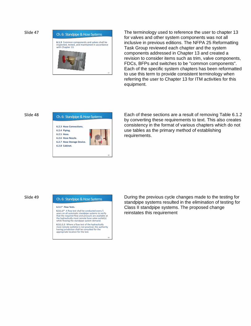
5.3.3.4.2 Newly introduced solutions shall be factory premixed antifreeze solutions (chemically pure or United States Pharmacopeia 96.5 percent).
5.3.3.4.3 Premixed antifreeze solutions of propylene glycol exceeding 30 percent concentration by volume shall be permitted for use with ESFR sprinklers where the ESFR sprinklers are listed for such use in
Slide 43 Ch. 5: Sprinkler Systems
43
5.4.1.2.2* Where replacing residential sprinklers manufactured prior to 2003 that are no longer available from the manufacturer and are installed using a design density less than 0.05 gpm/ft2 (204 mm/min), a residential sprinkler with an equivalent K-factor ( 5 percent) shall be permitted to be used provided the currently listed coverage area for the replacement sprinkler is not exceeded.
This new section has been added because in late 2002, the requirement for a minimum .05 density for listing of residential sprinklers and a minimum .10 density for NFPA 13 systems was added in the 2002 edition of NFPA 13. Prior to this time, there was no minimum density requirement. Many of those sprinklers are no longer manufactured. So when sprinklers need to be replaced, the owner needs an option. Many AHJ's are requiring that the system be recalculated with the new sprinkler listings and this means re-piping large portions of systems.
Slide 44 Table5.5.1Summary of Component Action Requirements
44
Table 5.5.1 has been revised to come into harmony with the requirements of NFPA 13 (2016) but only focuses on the NFPA 25 sprinkler replacement aspect of "modifications". This does not pick up modifying sprinkler piping.
Slide 45 Ch. 6: Standpipe & Hose Systems
45
Table 6.1.1.2 Summary of Standpipe and Hose Systems Inspection, Testing, and Maintenance
Reference to testing for hose storage devices has been deleted from the table. NFPA 1962 does not speak to the inspection or testing of standpipe system hose cabinets or hose storage devices such as pin racks or reels. Therefore, inspections for these components should fall under the requirement of Section 6.2.1 and since there are no tests prescribed for these components elsewhere, the reference to testing them in Table 6.1.1.2 has been deleted. In regard to Hose Connections, Chapter 13 only deals with the hose connections on pressure reducing valves, so Chapter 6 needs to address all other hose connections. All gauge requirements have been relocated to Ch 13. The references to sections outside of this chapter have been changed to simply reflect the chapter in which the requirement resides as opposed to the specific section.
Slide 46 Ch. 6: Standpipe & Hose Systems
46
6.1.2 Inspection, testing, and maintenance activities required by this chapter shall be followed to determine that components are free of corrosion, foreign material, physical damage, tampering, or other conditions that adversely affect system operation.
This section has been revised by removing Table 6.1.2 from the previous edition by converting the requirements contained in that table to text. This PI also creates consistency in the format of various chapters which do not use tables as the primary method of establishing requirements. [
Slide 47 Ch. 6: Standpipe & Hose Systems
47
6.1.3 Common components and valves shall be inspected, tested, and maintained in accordance with Chapter 13.
The terminology used to reference the user to chapter 13 for valves and other system components was not all inclusive in previous editions. The NFPA 25 Reformatting Task Group reviewed each chapter and the system components addressed in Chapter 13 and created a revision to consider items such as trim, valve components, FDCs, BFPs and switches to be "common components". Each of the specific system chapters has been reformatted to use this term to provide consistent terminology when referring the user to Chapter 13 for ITM activities for this equipment.
Slide 48 Ch. 6: Standpipe & Hose Systems
48
6.2.3 Hose Connections.
6.2.4 Piping.
6.2.5 Hose.
6.2.6 Hose Nozzle.
6.2.7 Hose Storage Device.
6.2.8 Cabinet.
Each of these sections are a result of removing Table 6.1.2 by converting these requirements to text. This also creates consistency in the format of various chapters which do not use tables as the primary method of establishing requirements.
Slide 49 Ch. 6: Standpipe & Hose Systems
49
6.3.1* Flow Tests.
6.3.1.1* A flow test shall be conducted every 5 years on all automatic standpipe systems to verify that the required flow and pressure are available at the hydraulically most remote hose valve outlet(s) while flowing the standpipe system demand.
6.3.1.1.1 Where a flow test of the hydraulically most remote outlet(s) is not practical, the authority having jurisdiction shall be consulted for the appropriate location for the test.
During the previous cycle changes made to the testing for standpipe systems resulted in the elimination of testing for Class II standpipe systems. The proposed change reinstates this requirement
Slide 50 Ch. 6: Standpipe & Hose Systems
50
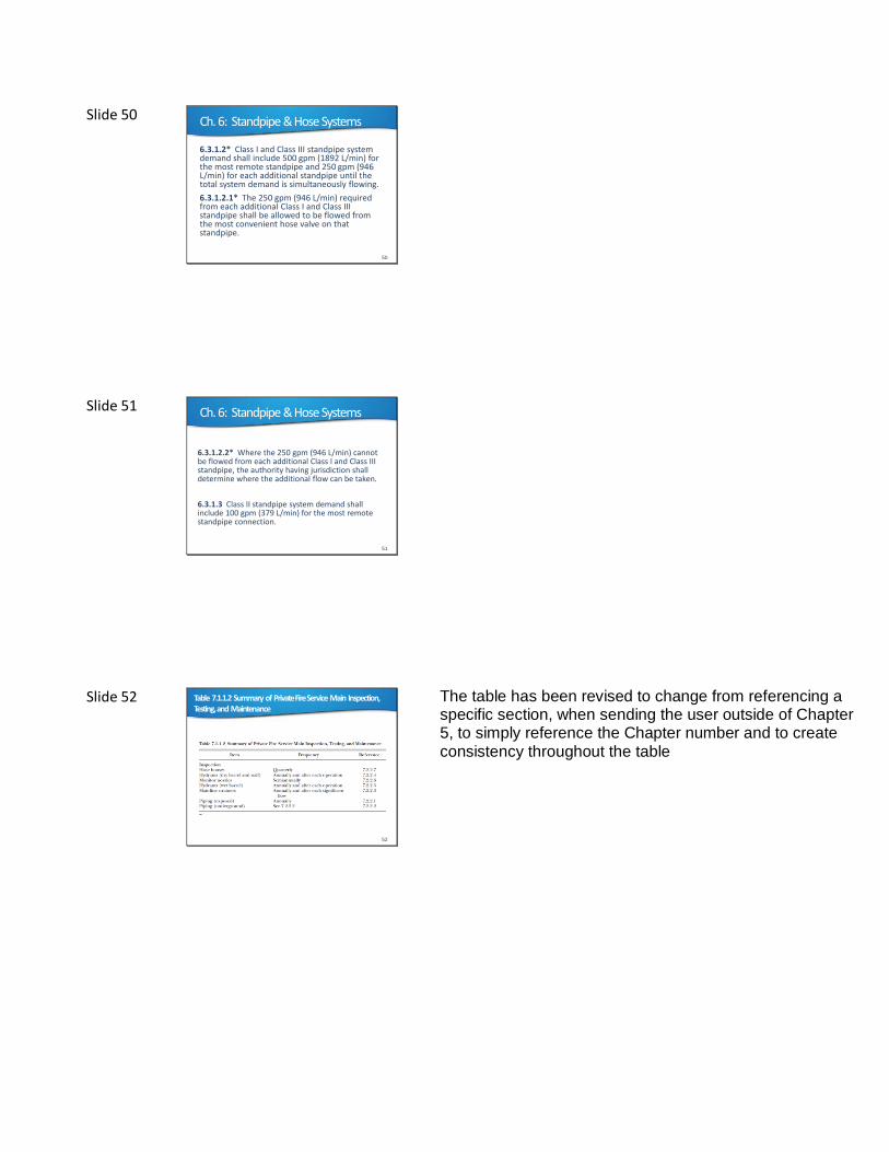
6.3.1.2* Class I and Class III standpipe system demand shall include 500 gpm (1892 L/min) for the most remote standpipe and 250 gpm (946 L/min) for each additional standpipe until the total system demand is simultaneously flowing.
6.3.1.2.1* The 250 gpm (946 L/min) required from each additional Class I and Class III standpipe shall be allowed to be flowed from the most convenient hose valve on that standpipe.
Slide 51 Ch. 6: Standpipe & Hose Systems
51
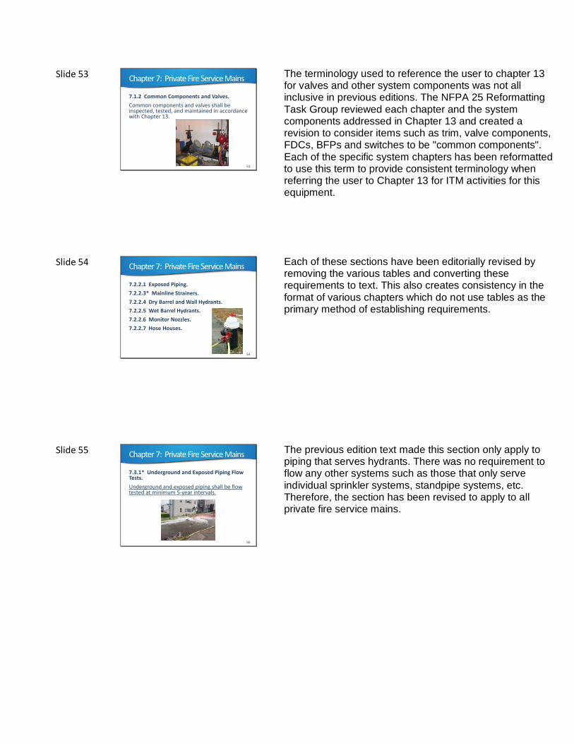
6.3.1.2.2* Where the 250 gpm (946 L/min) cannot be flowed from each additional Class I and Class III standpipe, the authority having jurisdiction shall determine where the additional flow can be taken.
6.3.1.3 Class II standpipe system demand shall include 100 gpm (379 L/min) for the most remote standpipe connection.
Slide 52 Table 7.1.1.2 Summary of Private Fire Service Main Inspection, Testing, and Maintenance
52
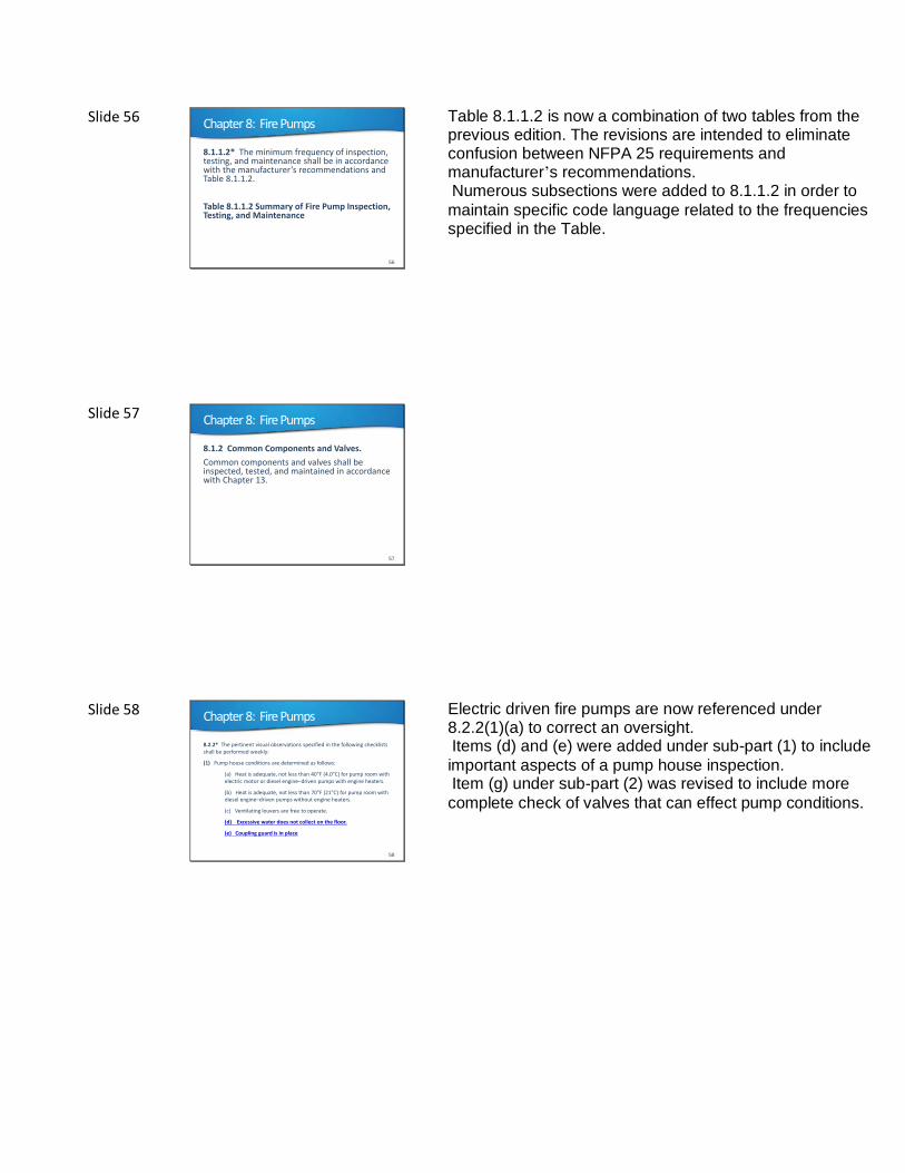
The table has been revised to change from referencing a specific section, when sending the user outside of Chapter 5, to simply reference the Chapter number and to create consistency throughout the table
Slide 53 Chapter 7: Private Fire Service Mains
7.1.2 Common Components and Valves.
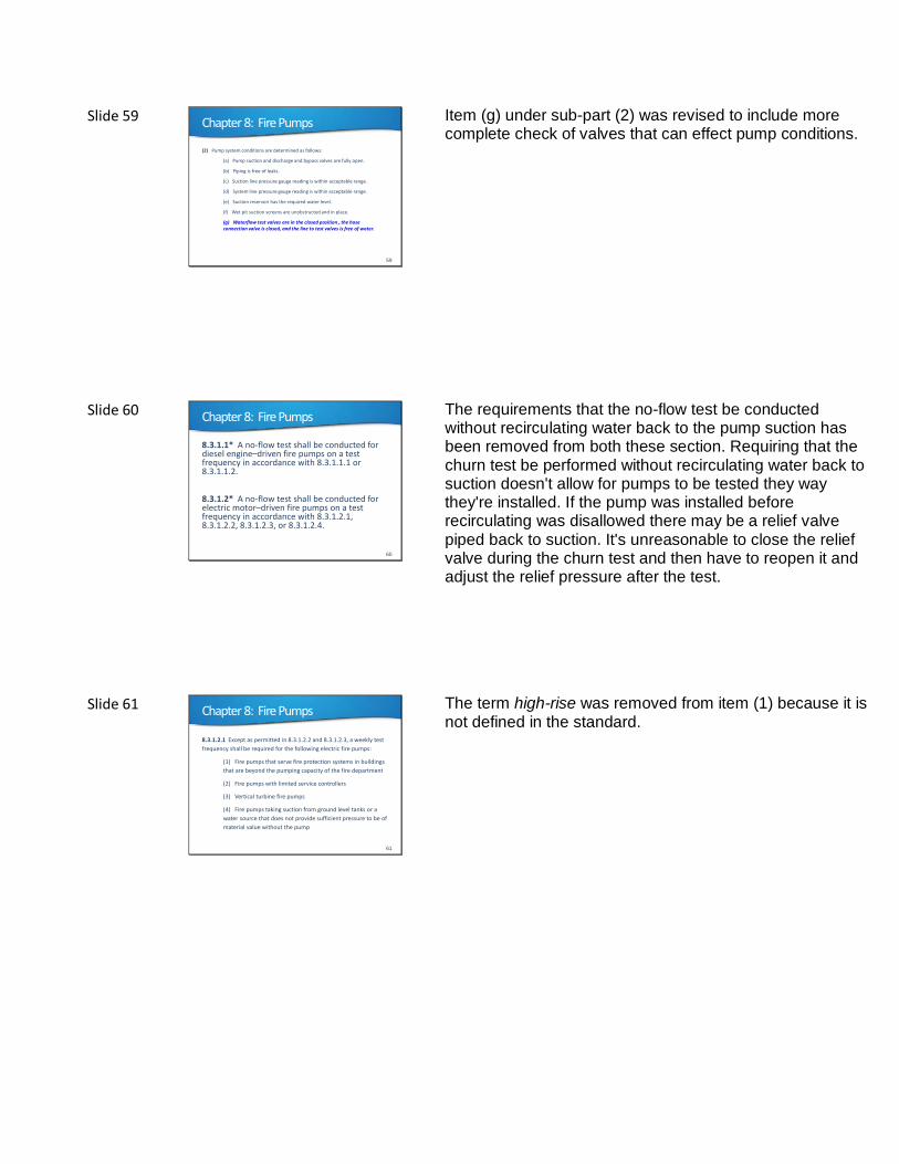
Common components and valves shall be inspected, tested, and maintained in accordance with Chapter 13.
53
The terminology used to reference the user to chapter 13 for valves and other system components was not all inclusive in previous editions. The NFPA 25 Reformatting Task Group reviewed each chapter and the system components addressed in Chapter 13 and created a revision to consider items such as trim, valve components, FDCs, BFPs and switches to be "common components". Each of the specific system chapters has been reformatted to use this term to provide consistent terminology when referring the user to Chapter 13 for ITM activities for this equipment.
Slide 54 Chapter 7: Private Fire Service Mains
7.2.2.1 Exposed Piping.
7.2.2.3* Mainline Strainers.
7.2.2.4 Dry Barrel and Wall Hydrants.
7.2.2.5 Wet Barrel Hydrants.
7.2.2.6 Monitor Nozzles.
7.2.2.7 Hose Houses.
54
Each of these sections have been editorially revised by removing the various tables and converting these requirements to text. This also creates consistency in the format of various chapters which do not use tables as the primary method of establishing requirements.
Slide 55 Chapter 7: Private Fire Service Mains
55
7.3.1* Underground and Exposed Piping Flow Tests.
Underground and exposed piping shall be flow tested at minimum 5-year intervals.
The previous edition text made this section only apply to piping that serves hydrants. There was no requirement to flow any other systems such as those that only serve individual sprinkler systems, standpipe systems, etc. Therefore, the section has been revised to apply to all private fire service mains.
Slide 56 Chapter 8: Fire Pumps
8.1.1.2* The minimum frequency of inspection, testing, and maintenance shall be in accordance with the manufacturer’s recommendations and Table 8.1.1.2.
Table 8.1.1.2 Summary of Fire Pump Inspection, Testing, and Maintenance
56
Table 8.1.1.2 is now a combination of two tables from the previous edition. The revisions are intended to eliminate confusion between NFPA 25 requirements and manufacturer’s recommendations. Numerous subsections were added to 8.1.1.2 in order to
maintain specific code language related to the frequencies specified in the Table.
Slide 57 Chapter 8: Fire Pumps
8.1.2 Common Components and Valves.
Common components and valves shall be inspected, tested, and maintained in accordance with Chapter 13.
57
Slide 58 Chapter 8: Fire Pumps
58
8.2.2* The pertinent visual observations specified in the following checklists shall be performed weekly:
(1) Pump house conditions are determined as follows:
(a) Heat is adequate, not less than 40 F (4.0 C) for pump room with electric motor or diesel engine–driven pumps with engine heaters.
(b) Heat is adequate, not less than 70 F (21 C) for pump room with diesel engine–driven pumps without engine heaters.
(c) Ventilating louvers are free to operate.
(d) Excessive water does not collect on the floor.
(e) Coupling guard is in place
Electric driven fire pumps are now referenced under 8.2.2(1)(a) to correct an oversight. Items (d) and (e) were added under sub-part (1) to include
important aspects of a pump house inspection. Item (g) under sub-part (2) was revised to include more
complete check of valves that can effect pump conditions.
Slide 59 Chapter 8: Fire Pumps
59
(2) Pump system conditions are determined as follows:
(a) Pump suction and discharge and bypass valves are fully open.
(b) Piping is free of leaks.
(c) Suction line pressure gauge reading is within acceptable range.
(d) System line pressure gauge reading is within acceptable range.
(e) Suction reservoir has the required water level.
(f) Wet pit suction screens are unobstructed and in place.
(g) Waterflow test valves are in the closed position , the hose connection valve is closed, and the line to test valves is free of water.
Item (g) under sub-part (2) was revised to include more complete check of valves that can effect pump conditions.
Slide 60 Chapter 8: Fire Pumps
60
8.3.1.1* A no-flow test shall be conducted for diesel engine–driven fire pumps on a test frequency in accordance with 8.3.1.1.1 or 8.3.1.1.2.
8.3.1.2* A no-flow test shall be conducted for electric motor–driven fire pumps on a test frequency in accordance with 8.3.1.2.1, 8.3.1.2.2, 8.3.1.2.3, or 8.3.1.2.4.
The requirements that the no-flow test be conducted without recirculating water back to the pump suction has been removed from both these section. Requiring that the churn test be performed without recirculating water back to suction doesn't allow for pumps to be tested they way they're installed. If the pump was installed before recirculating was disallowed there may be a relief valve piped back to suction. It's unreasonable to close the relief valve during the churn test and then have to reopen it and adjust the relief pressure after the test.
Slide 61 Chapter 8: Fire Pumps
61
8.3.1.2.1 Except as permitted in 8.3.1.2.2 and 8.3.1.2.3, a weekly test
frequency shall be required for the following electric fire pumps:
(1) Fire pumps that serve fire protection systems in buildings
that are beyond the pumping capacity of the fire department
(2) Fire pumps with limited service controllers
(3) Vertical turbine fire pumps
(4) Fire pumps taking suction from ground level tanks or a
water source that does not provide sufficient pressure to be of
material value without the pump
The term high-rise was removed from item (1) because it is not defined in the standard.
Slide 62 Chapter 8: Fire Pumps
62
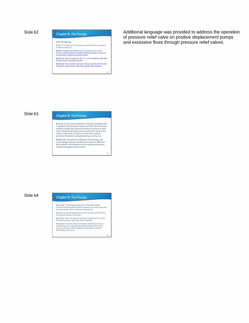
8.3.2* No-Flow Test.
8.3.2.1 A no-flow test of fire pump assemblies shall be conducted in accordance with 8.3.2.
8.3.2.1.1 Except as permitted in 8.3.2.1.2 and 8.3.2.1.3, a main pressure relief valve (where installed) shall be permitted to weep but not discharge a significant quantity of water.
8.3.2.1.1.1 Except as required in 8.3.2.1.1.2, the circulation relief valve shall discharge a small flow of water.
8.3.2.1.1.2 The circulation relief valve shall not operate when the flow through the main pressure relief valve is greater than weeping.
Additional language was provided to address the operation of pressure relief valve on positive displacement pumps and excessive flows through pressure relief valves.
Slide 63 Chapter 8: Fire Pumps
63
8.3.2.1.2 For fire pump installations that were installed under a standard (1993 and earlier editions of NFPA 20) that did not prohibit a design that required operation of a pressure relief valve to keep the discharge pressure below the rating of the system components, the pressure relief valve shall be permitted to operate as designed during a no-flow test.
8.3.2.1.2.1* The pressure readings on the discharge and suction gauges shall be recorded, and a pressure difference that is greater than 95 percent of the rated pump pressure shall be investigated and corrected.
Slide 64 Chapter 8: Fire Pumps
64
8.3.2.1.2.2* The discharge temperature of the water shall be monitored and the pump shut down if necessary to prevent exposing the pump and/or driver to excessive temperatures.
8.3.2.1.3 For positive displacement pumps, the pressure relief valve shall operate during a no-flow test.
8.3.2.1.3.1 Where the pressure relief valve is piped back to suction, the pump circulation relief valve shall not operate.
8.3.2.1.3.2 On electric motor and radiator cooled engine drives, a circulation pressure relief valve located downstream of the main pressure relief valve shall discharge sufficient water to prevent overheating of the pump.
Slide 65 Chapter 8: Fire Pumps
65
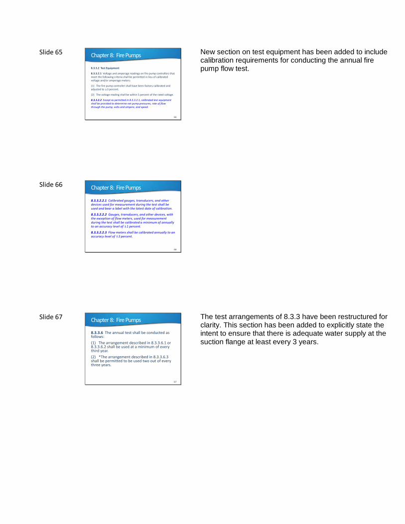
8.3.3.2 Test Equipment
8.3.3.2.1 Voltage and amperage readings on fire pump controllers that meet the following criteria shall be permitted in lieu of calibrated voltage and/or amperage meters:
(1) The fire pump controller shall have been factory calibrated and adjusted to 3 percent.
(2) The voltage reading shall be within 5 percent of the rated voltage.
8.3.3.2.2 Except as permitted in 8.3.3.2.1, calibrated test equipment shall be provided to determine net pump pressures, rate of flow through the pump, volts and ampere, and speed.
New section on test equipment has been added to include calibration requirements for conducting the annual fire pump flow test.
Slide 66 Chapter 8: Fire Pumps
66
8.3.3.2.2.1 Calibrated gauges, transducers, and other devices used for measurement during the test shall be used and bear a label with the latest date of calibration.
8.3.3.2.2.2 Gauges, transducers, and other devices, with the exception of flow meters, used for measurement during the test shall be calibrated a minimum of annually to an accuracy level of 1 percent.
8.3.3.2.2.3 Flow meters shall be calibrated annually to an accuracy level of 3 percent.
Slide 67 Chapter 8: Fire Pumps
67
8.3.3.6 The annual test shall be conducted as follows:
(1) The arrangement described in 8.3.3.6.1 or 8.3.3.6.2 shall be used at a minimum of every third year.
(2) *The arrangement described in 8.3.3.6.3 shall be permitted to be used two out of every three years.
The test arrangements of 8.3.3 have been restructured for clarity. This section has been added to explicitly state the intent to ensure that there is adequate water supply at the suction flange at least every 3 years.
Slide 68 Chapter 8: Fire Pumps
68
8.3.3.9 For installations having an automatic transfer switch, the following test shall be performed to ensure that the overcurrent protective devices (i.e., fuses or circuit breakers) do not open:
(1) Simulate a power failure condition while the pump is operating at peak load.
(2) Verify that the transfer switch transfers power to the alternate power source.
(3) While the pump is operating at peak load and alternate power, record the voltage, amperage, rpm, suction pressure, discharge pressure, and flow rate and include in the pump test results.
(4) Verify that the pump continues to perform at peak horsepower load on the alternate power source for a minimum of 2 minutes.
(5) Remove the power failure condition and verify that, after a time delay, the pump is reconnected to the normal power source.
The test of the alternate power source at peak horsepower in item (4) was reduced to 2 minutes. While a full load test is preferable, an extended churn test is acceptable to reduce water usage.
Slide 69 Chapter 8: Fire Pumps
69
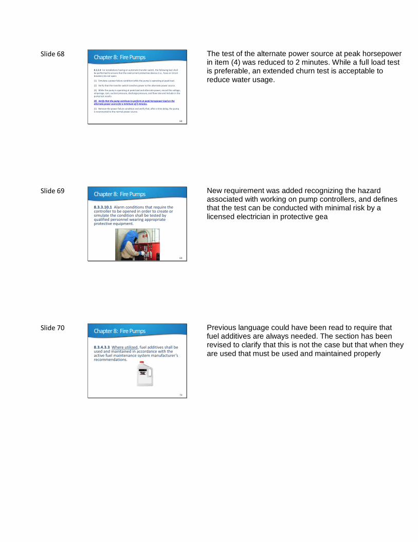
8.3.3.10.1 Alarm conditions that require the controller to be opened in order to create or simulate the condition shall be tested by qualified personnel wearing appropriate protective equipment.
New requirement was added recognizing the hazard associated with working on pump controllers, and defines that the test can be conducted with minimal risk by a licensed electrician in protective gea
Slide 70 Chapter 8: Fire Pumps
70
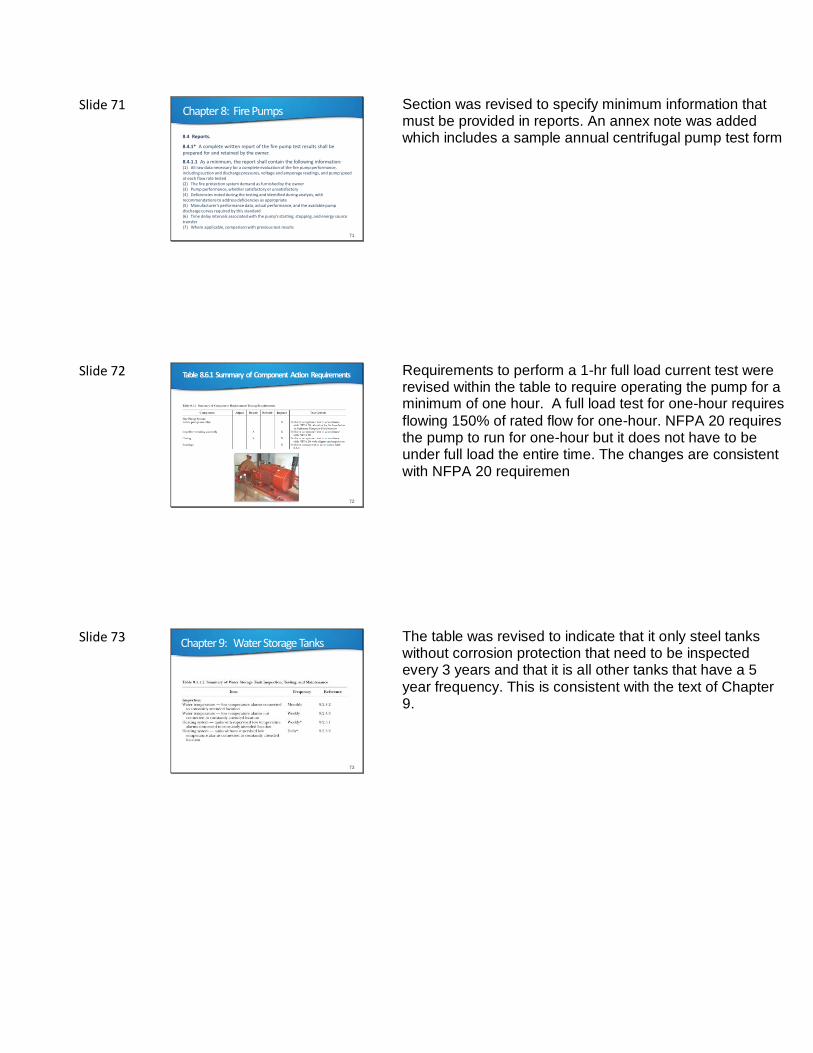
8.3.4.3.3 Where utilized, fuel additives shall be used and maintained in accordance with the active fuel maintenance system manufacturer’s recommendations.
Previous language could have been read to require that fuel additives are always needed. The section has been revised to clarify that this is not the case but that when they are used that must be used and maintained properly
Slide 71 Chapter 8: Fire Pumps
71
8.4 Reports.
8.4.1* A complete written report of the fire pump test results shall be prepared for and retained by the owner.
8.4.1.1 As a minimum, the report shall contain the following information:(1) All raw data necessary for a complete evaluation of the fire pump performance, including suction and discharge pressures, voltage and amperage readings, and pump speed at each flow rate tested(2) The fire protection system demand as furnished by the owner(3) Pump performance, whether satisfactory or unsatisfactory(4) Deficiencies noted during the testing and identified during analysis, with recommendations to address deficiencies as appropriate(5) Manufacturer’s performance data, actual performance, and the available pump discharge curves required by this standard(6) Time delay intervals associated with the pump’s starting, stopping, and energy source transfer(7) Where applicable, comparison with previous test results
Section was revised to specify minimum information that must be provided in reports. An annex note was added which includes a sample annual centrifugal pump test form
Slide 72 Table 8.6.1 Summary of Component Action Requirements
72
Requirements to perform a 1-hr full load current test were revised within the table to require operating the pump for a minimum of one hour. A full load test for one-hour requires
flowing 150% of rated flow for one-hour. NFPA 20 requires the pump to run for one-hour but it does not have to be under full load the entire time. The changes are consistent with NFPA 20 requiremen
Slide 73 Chapter 9: Water Storage Tanks
73
The table was revised to indicate that it only steel tanks without corrosion protection that need to be inspected every 3 years and that it is all other tanks that have a 5 year frequency. This is consistent with the text of Chapter 9.
Slide 74 Chapter 9: Water Storage Tanks
74
9.1.2 Common Components and Valves.
Common components and valves shall be inspected, tested, and maintained in accordance with Chapter 13.
The terminology used to reference the user to chapter 13 for valves and other system components was not all inclusive in previous editions. The NFPA 25 Reformatting Task Group reviewed each chapter and the system components addressed in Chapter 13 and created a revision to consider items such as trim, valve components, FDCs, BFPs and switches to be "common components". Each of the specific system chapters has been reformatted to use this term to provide consistent terminology when referring the user to Chapter 13 for ITM activities for this equipment.
Slide 75 Chapter 9: Water Storage Tanks
75
9.2.1 Water Level.
9.2.1.1* The water level in tanks equipped with supervised water level alarms that are supervised in accordance with NFPA 72 shall be inspected quarterly.
9.2.1.2 The water level in tanks not equipped with supervised water level alarms connected to a constantly attended location shall be inspected monthly.
All tank inspection frequencies have been revised to quarterly where the components are supervised in accordance with NFPA 72. All frequencies for components not supervised in accordance with NFPA 72 have remained unchanged.
Slide 76 Chapter 9: Water Storage Tanks
76
9.2.2 Heating System.
9.2.2.1 Tank heating systems installed on tanks equipped with low water temperature alarms supervised in accordance with NFPA 72, connected to a constantly attended location shall be inspected quarterly during the heating season.
9.2.2.2 Tank heating systems without a supervised low temperature alarm connected to a constantly attended location shall be inspected daily during the heating season.
Section 9.2.2.1 was revised to indicate that the inspections are only required during heating season, similar to what 9.2.2.2 said in previous editions.
Slide 77 Chapter 9: Water Storage Tanks
77
9.2.3 Water Temperature.
9.2.3.1 The temperature of water in tanks shall not be less than 40 F (4.0 C).
9.2.3.2 The temperature of water in tanks with low temperature alarms supervised in accordance with NFPA 72, connected to a constantly attended location shall be inspected and recorded quarterly during the heating season when the mean temperature is less than 40 F (4.0 C).
9.2.3.3 The temperature of water in tanks without low temperature alarms connected to a constantly attended location shall be inspected and recorded weekly during the heating season when the mean temperature is less than 40 F (4.0 C).
Slide 78 Chapter 9: Water Storage Tanks
78
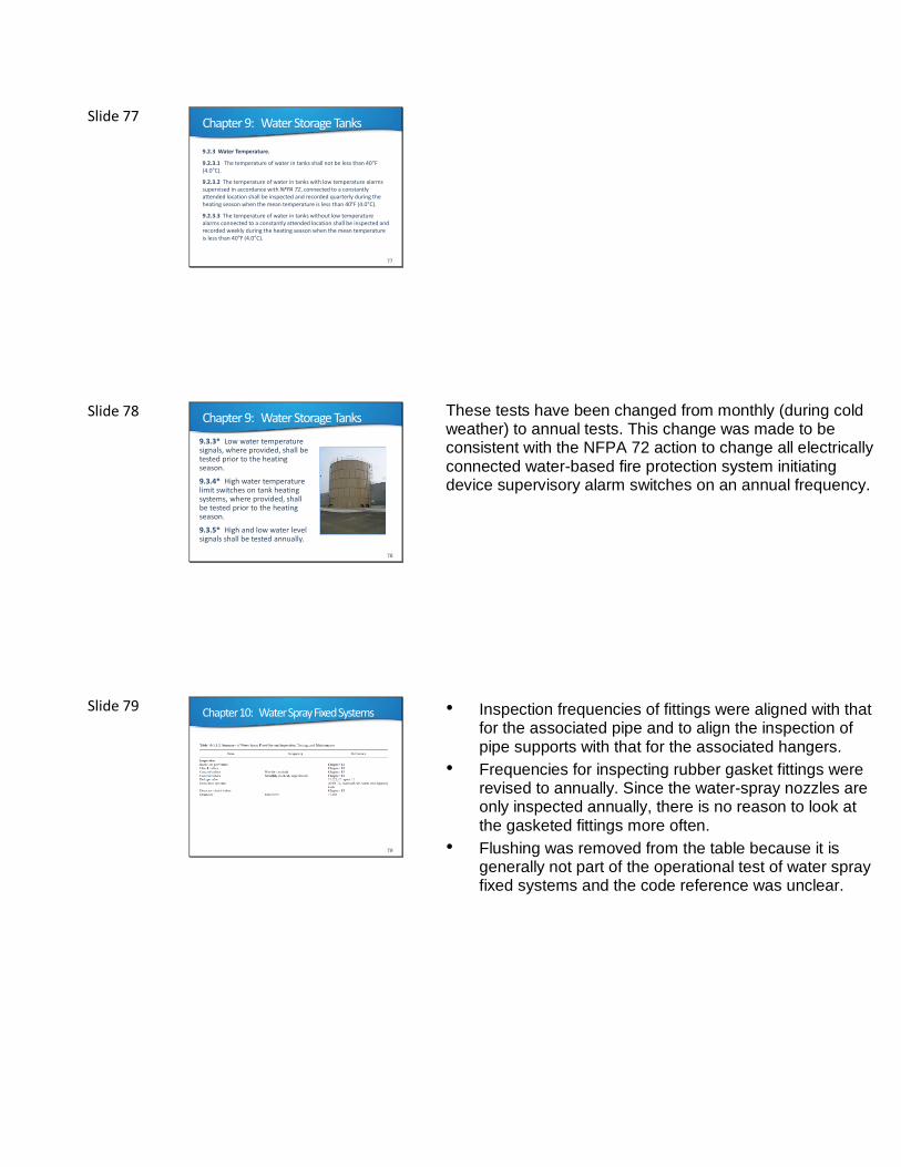
9.3.3* Low water temperature signals, where provided, shall be tested prior to the heating season.
9.3.4* High water temperature limit switches on tank heating systems, where provided, shall be tested prior to the heating season.
9.3.5* High and low water level signals shall be tested annually.
These tests have been changed from monthly (during cold weather) to annual tests. This change was made to be consistent with the NFPA 72 action to change all electrically connected water-based fire protection system initiating device supervisory alarm switches on an annual frequency.
Slide 79 Chapter 10: Water Spray Fixed Systems
79
• Inspection frequencies of fittings were aligned with that for the associated pipe and to align the inspection of pipe supports with that for the associated hangers.
• Frequencies for inspecting rubber gasket fittings were revised to annually. Since the water-spray nozzles are only inspected annually, there is no reason to look at the gasketed fittings more often.
• Flushing was removed from the table because it is generally not part of the operational test of water spray fixed systems and the code reference was unclear.
Slide 80 Chapter 10: Water Spray Fixed Systems
80
10.1.5 Common Components and Valves.
Common components and valves shall be inspected, tested, and maintained in accordance with Chapter 13.
The terminology used to reference the user to chapter 13 for valves and other system components was not all inclusive in previous editions. The NFPA 25 Reformatting Task Group reviewed each chapter and the system components addressed in Chapter 13 and created a revision to consider items such as trim, valve components, FDCs, BFPs and switches to be "common components". Each of the specific system chapters has been reformatted to use this term to provide consistent terminology when referring the user to Chapter 13 for ITM activities for this equipment. ]
Slide 81 Chapter 10: Water Spray Fixed Systems
81
10.2.3.1* Piping and Fittings. System piping and fittings shall be inspected for the following:
(1) Mechanical damage (e.g., broken piping or cracked fittings)
(2) External conditions (e.g., missing or damaged paint or coatings,
rust, and corrosion)
(3) Misalignment or trapped sections
(4) Condition of low-point drains (automatic or manual)
(5) Protection for rubber-gasketed fittings
This section was revised to clarify that the intent of section item (4) is to inspect the condition of any installed low-point drains. As previously written this was not clear. Additionally, the protection of gaskets has been clarified and the intent would be consistent with the requirements of NFPA 15.
Slide 82 Chapter 10: Water Spray Fixed Systems
82
10.2.3.2* Hangers, Braces, and Supports.
Hangers, braces, and supports shall be inspected for the following and repaired or replaced as necessary:
(1) Condition (e.g., missing or damaged paint or coating, rust, and corrosion)
(2) Secure attachment to structural supports and piping
(3) Damaged or missing hangers, braces, and supports
Braces have been added to this section. The inspection of seismic braces is required for sprinkler systems in Chapter 5 and should also be required for water spray systems.
Slide 83 Chapter 11: Foam-Water Systems
83
References in the table have been revised to shift the ITM requirements for waterflow devices to Chapter 13. A new row for Gauges has been added because, as with all water-based systems, gauges should be inspected regularly, but were previously omitted from this table.
Slide 84 Chapter 11: Foam-Water Systems
84
11.1.2 Other System Components.
Fire pumps, water storage tanks, common components, and valves common to other types of water-based fire protection systems shall be inspected, tested, and maintained in accordance with Chapters 8, 9, and 13, respectively, and as specified in Table 11.1.1.2.
The terminology used to reference the user to chapter 13 for valves and other system components was not all inclusive in previous editions. The NFPA 25 Reformatting Task Group reviewed each chapter and the system components addressed in Chapter 13 and created a revision to consider items such as trim, valve components, FDCs, BFPs and switches to be "common components". Each of the specific system chapters has been reformatted to use this term to provide consistent terminology when referring the user to Chapter 13 for ITM activities for this equipment.
Slide 85 Chapter 11: Foam-Water Systems
85
11.1.4.1 If during routine inspection and testing the foam-water
sprinkler system is determined to have been altered or replaced (e.g., equipment replaced, relocated, or foam concentrate
replaced), it shall be determined whether the system operates properly.
Requirement that the inspector determine if the design intent has been altered has been removed from this section because the inspector is typically not qualified to determine whether the design intent has been altered and whether the system operates properly.
Slide 86 Chapter 11: Foam-Water Systems
86
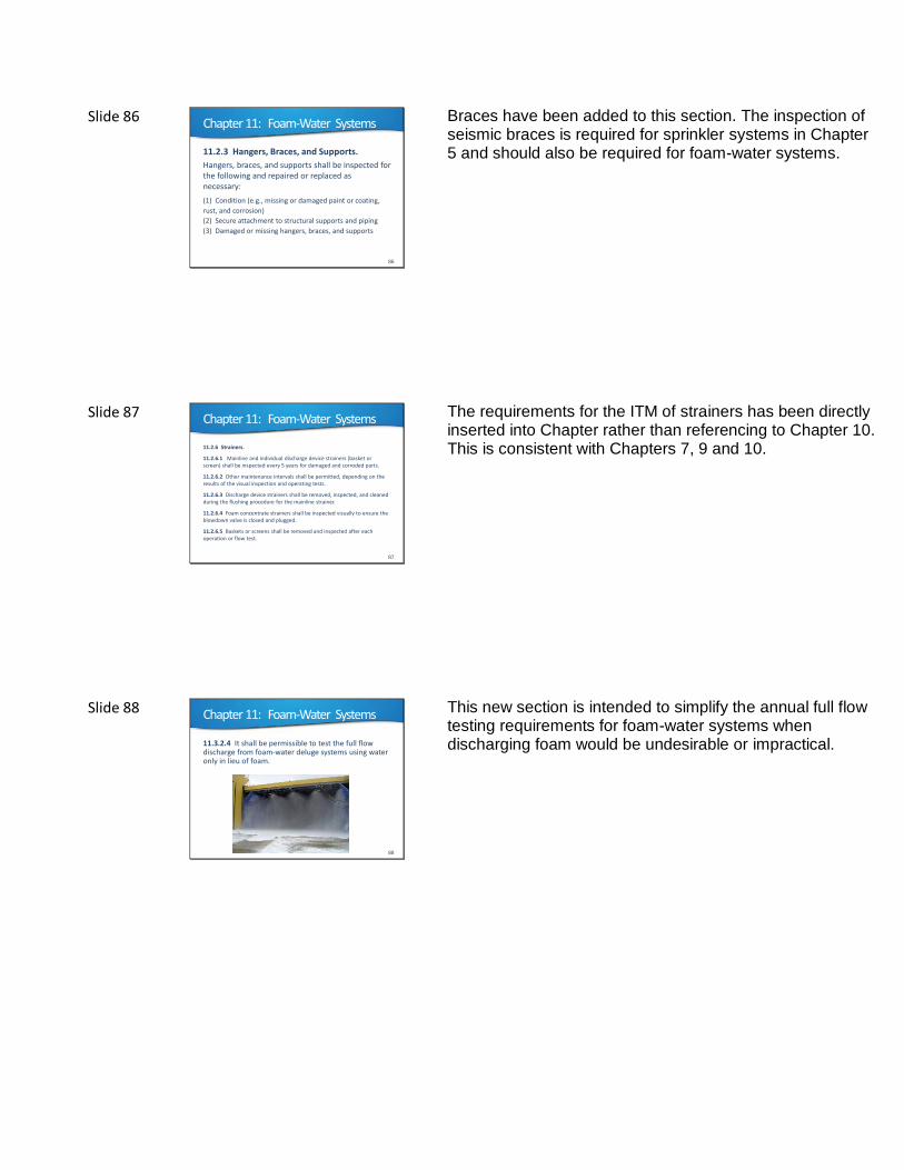
11.2.3 Hangers, Braces, and Supports.
Hangers, braces, and supports shall be inspected for the following and repaired or replaced as necessary:
(1) Condition (e.g., missing or damaged paint or coating,
rust, and corrosion)
(2) Secure attachment to structural supports and piping
(3) Damaged or missing hangers, braces, and supports
Braces have been added to this section. The inspection of seismic braces is required for sprinkler systems in Chapter 5 and should also be required for foam-water systems.
Slide 87 Chapter 11: Foam-Water Systems
87
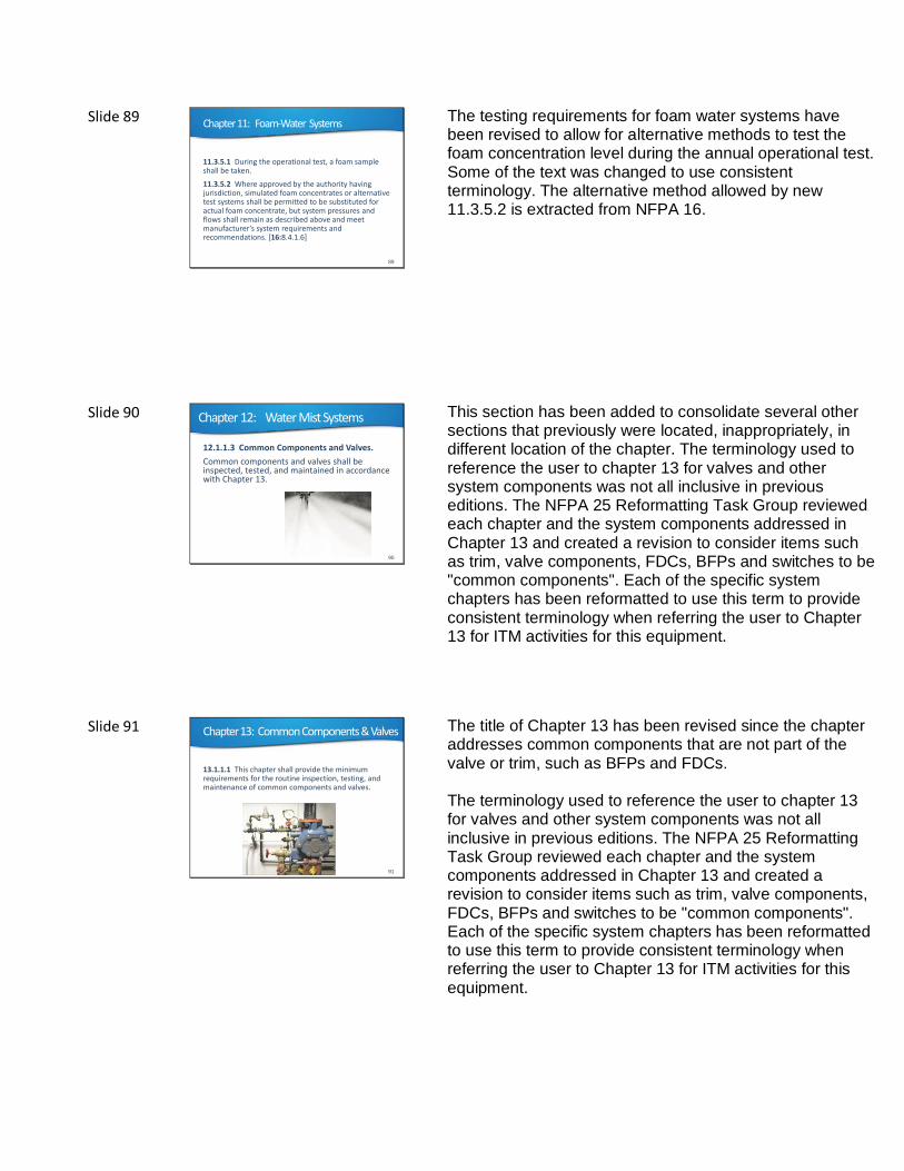
11.2.6 Strainers.
11.2.6.1 Mainline and individual discharge device strainers (basket or screen) shall be inspected every 5 years for damaged and corroded parts.
11.2.6.2 Other maintenance intervals shall be permitted, depending on the results of the visual inspection and operating tests.
11.2.6.3 Discharge device strainers shall be removed, inspected, and cleaned during the flushing procedure for the mainline strainer.
11.2.6.4 Foam concentrate strainers shall be inspected visually to ensure the blowdown valve is closed and plugged.
11.2.6.5 Baskets or screens shall be removed and inspected after each operation or flow test.
The requirements for the ITM of strainers has been directly inserted into Chapter rather than referencing to Chapter 10. This is consistent with Chapters 7, 9 and 10.
Slide 88 Chapter 11: Foam-Water Systems
88
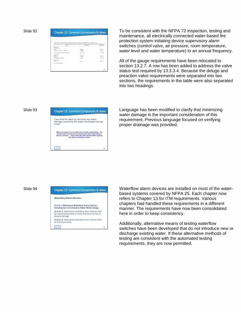
11.3.2.4 It shall be permissible to test the full flow discharge from foam-water deluge systems using water only in lieu of foam.
This new section is intended to simplify the annual full flow testing requirements for foam-water systems when discharging foam would be undesirable or impractical.
Slide 89 Chapter 11: Foam-Water Systems
89
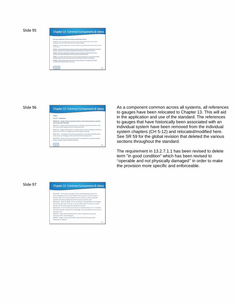
11.3.5.1 During the operational test, a foam sample shall be taken.
11.3.5.2 Where approved by the authority having jurisdiction, simulated foam concentrates or alternative test systems shall be permitted to be substituted for actual foam concentrate, but system pressures and flows shall remain as described above and meet manufacturer’s system requirements and recommendations. [16:8.4.1.6]
The testing requirements for foam water systems have been revised to allow for alternative methods to test the foam concentration level during the annual operational test. Some of the text was changed to use consistent terminology. The alternative method allowed by new 11.3.5.2 is extracted from NFPA 16.
Slide 90 Chapter 12: Water Mist Systems
90
12.1.1.3 Common Components and Valves.
Common components and valves shall be inspected, tested, and maintained in accordance with Chapter 13.
This section has been added to consolidate several other sections that previously were located, inappropriately, in different location of the chapter. The terminology used to reference the user to chapter 13 for valves and other system components was not all inclusive in previous editions. The NFPA 25 Reformatting Task Group reviewed each chapter and the system components addressed in Chapter 13 and created a revision to consider items such as trim, valve components, FDCs, BFPs and switches to be "common components". Each of the specific system chapters has been reformatted to use this term to provide consistent terminology when referring the user to Chapter 13 for ITM activities for this equipment.
Slide 91 Chapter 13: Common Components & Valves
13.1.1.1 This chapter shall provide the minimum requirements for the routine inspection, testing, and maintenance of common components and valves.
91
The title of Chapter 13 has been revised since the chapter addresses common components that are not part of the valve or trim, such as BFPs and FDCs. The terminology used to reference the user to chapter 13 for valves and other system components was not all inclusive in previous editions. The NFPA 25 Reformatting Task Group reviewed each chapter and the system components addressed in Chapter 13 and created a revision to consider items such as trim, valve components, FDCs, BFPs and switches to be "common components". Each of the specific system chapters has been reformatted to use this term to provide consistent terminology when referring the user to Chapter 13 for ITM activities for this equipment.
Slide 92 Chapter 13: Common Components & Valves
92
To be consistent with the NFPA 72 inspection, testing and maintenance, all electrically connected water-based fire protection system initiating device supervisory alarm switches (control valve, air pressure, room temperature, water level and water temperature) to an annual frequency. All of the gauge requirements have been relocated to section 13.2.7. A row has been added to address the valve status test required by 13.3.3.4. Because the deluge and preaction valve requirements were separated into two sections, the requirements in the table were also separated into two headings
Slide 93
Care shall be taken to minimize any water damage caused by the water discharged during a test.
13.2.4 93
Chapter 13: Common Components & Valves
While new section 4.1.1.2.1 makes this an owner responsibility – this
section makes the ITM service provider aware that responsibility is
shared in practice… Know where the water will flow before opening
any valves or flowing any water!
Language has been modified to clarify that minimizing water damage is the important consideration of this requirement. Previous language focused on verifying proper drainage was provided.
Slide 94
Waterflow Alarm Devices.
13.2.6.1 Mechanical Waterflow Alarm Devices, Including but not Limited to Water Motor Gongs.
13.2.6.1.1 Mechanical waterflow alarm devices shall be inspected quarterly to verify that they are free of physical damage
13.2.6.1.2 Mechanical waterflow alarm devices shall be tested quarterly.
13.2.6* 94
Chapter 13: Common Components & Valves
Waterflow alarm devices are installed on most of the water-based systems covered by NFPA 25. Each chapter now refers to Chapter 13 for ITM requirements. Various chapters had handled these requirements in a different manner. The requirements have now been consolidated here in order to keep consistency.
Additionally, alternative means of testing waterflow switches have been developed that do not introduce new or discharge existing water. If these alternative methods of testing are consistent with the automated testing requirements, they are now permitted.
Slide 95
Vane-type, Paddle-type, and Pressure Switch–type Waterflow Devices.
13.2.6.2.1 Vane-type, paddle-type, and pressure switch-type waterflow alarm devices shall be inspected quarterly to verify that they are free of physical damage.
13.2.6.2.2 Vane-type, paddle-type, and pressure switch-type waterflow alarm devices shall be tested semiannually.
13.2.6.3 Testing waterflow alarm devices on wet pipe systems shall be accomplished by opening the inspector's test valve or by using the automated test equipment in accordance with 4.6.6.
13.2.6.4 Where freezing weather conditions or other circumstances prohibits the use of the inspector's test valve, the bypass connection shall be permitted to be used.
13.2.6.5 Fire pumps shall not be taken out of service during testing unless constantly attended by qualified personnel, or all impairment procedures contained in Chapter 15 are followed.
13.2.6.6* Testing waterflow alarm devices on dry pipe, preaction, or deluge systems shall be accomplished by using the bypass connection.
13.2.6.2 95
Chapter 13: Common Components & Valves
Slide 96
Gauges.
13.2.7.1* Inspections.
13.2.7.1.1* Gauges shall be inspected monthly to verify that the gauge is operable and not physically damaged.
13.2.7.1.2 Gauges monitoring water pressure shall be inspected quarterly to verify that normal water supply pressure is being maintained.
13.2.7.1.3 Gauges monitoring air or nitrogen pressure shall be inspected monthly to verify that normal air or nitrogen pressure are being maintained.
13.2.7.1.3.1 The gauge on the quick-opening device, if provided, shall indicate the same pressure as the gauge on the system side of the dry pipe valve.
13.2.7.1.3.2 Where air pressure supervision is connected to a constantly attended location, gauges shall be inspected quarterly.
13.2.7 96
Chapter 13: Common Components & Valves
As a component common across all systems, all references to gauges have been relocated to Chapter 13. This will aid in the application and use of the standard. The references to gauges that have historically been associated with an individual system have been removed from the individual system chapters (CH 5-12) and relocated/modified here. See SR 59 for the global revision that deleted the various sections throughout the standard. The requirement in 13.2.7.1.1 has been revised to delete term "in good condition" which has been revised to “operable and not physically damaged” in order to make the provision more specific and enforceable.
Slide 97
13.2.7.1.4* For dry pipe or preaction systems protecting freezers with an air
pressure gauge(s) on the air line(s) between the compressor and the dry pipe or
preaction valve, the air pressure gauge near the compressor shall be compared
monthly to the pressure gauge above the dry pipe or preaction valve.
13.2.7.1.4.1 When the gauge near the compressor is reading higher than the gauge
near the dry pipe valve, the air line in service shall be taken out of service and the
alternate air line shall be opened to equalize the pressure.
13.2.7.1.4.2 An air line taken out of service in accordance with 13.2.7.1.4.1 shall be
internally inspected, removed of all ice blockage, and reassembled for use as a future
alternate air line.
13.2.7.2* Gauges shall be replaced every 5 years or tested every 5 years by
comparison with a calibrated gauge.
13.2.7.3 Gauges not accurate to within 3 percent of the full scale shall be
recalibrated or replaced.
97
Chapter 13: Common Components & Valves
Slide 98
Supervisory Signal Devices (except valve supervisory
switches).
13.2.8.1 Supervisory signal devices shall be inspected quarterly to verify that they are free of physical damage.
13.2.8.2 Supervisory signal devices shall be tested annually in accordance with the manufacturer’s instructions.
13.2.8 98
Chapter 13: Common Components & Valves
This new section has been added because Table 5.1.1.2 (and others) direct the user to Chapter 13 for the ITM of Supervisory Signal Devices (except valve supervisory switches), but the only comparable requirements previously found in Chapter 13 were specific to only low pressure switch testing for dry and preaction systems. This revision adds general requirements pertaining to other supervisory devices (ie. wet pipe system low or high pressure switches, etc.)
Slide 99
13.3.2.1.2 Valves that are electrically supervised shall be permitted to be inspected quarterly.
99
Chapter 13: Common Components & Valves
This section has been added to allow for quarterly inspections where electric supervision is provided. This provides consistency with other inspections and tests. This change is intended to improve application and compliance with the standard.
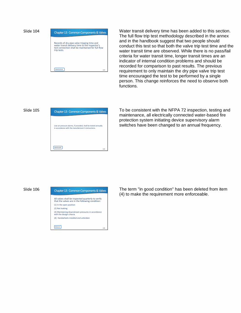
Slide 100
13.3.3.4* A valve status test shall be conducted any time the control valve is closed and reopened at system riser.
100
Chapter 13: Common Components & Valves
The language has been revised to require a valve status test as opposed to a main drain test as was previously required. There are a number of ways in which a test can be conducted to ensure the valve has been reopened. Requiring a full main drain test on all systems annually would negate the allowance provided in the 2014 edition for a single main drain test for the water supply serving multiple systems, including every floor of a multi-story building with floor control valve assemblies.
Slide 101
Alarm valves and system riser check valves shall be externally inspected quarterly and shall verify the following:
(1) The gauges indicate normal supply water pressure is being maintained.
(2) The valves and trim are free of physical damage.
(3) All valves are in the appropriate open or closed position.
(4) The retarding chamber or alarm drains are not leaking.
13.4.1.1* 101
Chapter 13: Common Components & Valves
The frequency for inspection has been revised to quarterly rather than monthly, as was previously required. This change was made because damage is a rare event and failure is typically “open.” Additionally, item (2) was revised to specify that the trim is also intended to be inspected for physical damage.
Slide 102
Inspection.
Valves shall be inspected internally every 5 years to verify that all of the valve’s components operate correctly.
13.4.2.1 102
Chapter 13: Common Components & Valves
The term “in good condition” was deleted to make the requirement more enforceable.
Slide 103
13.4.3 Preaction Valves.
13.4.4 Deluge Valves.
103
Chapter 13: Common Components & Valves
Section 13.4.3 previously contained requirements for both preaction and deluge systems. These are different system types with distinctly different ITM activities. Therefore, they have been separated into two sections to make the standard easier to follow. Additionally, when the requirements for preaction valves and deluge valves were split into two sections, there were a number of items related to the deluge valve trip testing that needed correction or clarification.
Slide 104
Records of dry pipe valve tripping time and water transit delivery time to the inspector's test connection shall be maintained for full flow trip tests.
13.4.5.2.5.2 104
Chapter 13: Common Components & Valves
Water transit delivery time has been added to this section. The full flow trip test methodology described in the annex and in the handbook suggest that two people should conduct this test so that both the valve trip test time and the water transit time are observed. While there is no pass/fail criteria for water transit time, longer transit times are an indicator of internal condition problems and should be recorded for comparison to past results. The previous requirement to only maintain the dry pipe valve trip test time encouraged the test to be performed by a single person. This change reinforces the need to observe both functions.
Slide 105
Low air pressure alarms, if provided, shall be tested annually in accordance with the manufacturer’s instructions.
13.4.5.2.6*105
Chapter 13: Common Components & Valves
To be consistent with the NFPA 72 inspection, testing and maintenance, all electrically connected water-based fire protection system initiating device supervisory alarm switches have been changed to an annual frequency.
Slide 106
All valves shall be inspected quarterly to verify that the valves are in the following condition:
(1) In the open position
(2) Not leaking
(3) Maintaining downstream pressures in accordance with the design criteria
(4) Handwheels installed and unbroken
13.5.1.1106
Chapter 13: Common Components & Valves
The term "in good condition" has been deleted from item (4) to make the requirement more enforceable.
Slide 107
Devices shall be inspected weekly to verify that the devices are in the following condition:
(1) *Normal downstream pressures are maintained.
(2) Normal supply pressure is maintained.
(3) Devices and associated trim components are free of physical damage and are not leaking.
13.5.4.1
107
Chapter 13: Common Components & Valves
Requirement that devices be "in good condition" has been deleted to make the requirement more enforceable.
Previous text that required checking the supply pressure being in accordance with the design criteria was revised to be an inspection that normal supply pressure is being maintained. It is not practical to expect that an ITM inspector knows the design criteria to which the pressure regulating device was set for. Additionally, item (3) was revised to ensure that the various trim components such as relief valves and the pressure gauges are also checked.
Slide 108
Fire department connections shall be inspected quarterly to verify the following:
(1) Fire department connections are visible and accessible.(2) Couplings or swivels are not damaged and rotate smoothly.(3) Plugs or caps are in place and undamaged.(4) Gaskets are in place.(5) Identification signs are in place.(6) Check valve is not leaking.(7) Automatic drain valve is in place and operating properly.(8) Fire department connection clapper(s) is in place and operating properly.(9) *Interior of the connection is inspected for obstructions.(10) Visible piping supplying the fire department connection is undamaged.
13.8.1108
Chapter 13: Common Components & Valves
Item (10) has been added to require inspection of the piping supplying the FDC. Fire department connections are frequently located in areas that are subject to vehicular or other damage. This section of piping may not be under pressure as the check valve could be located back at the riser leaving a large length of piping unpressurized and without a visual indication (leak) if the pipe suplying the FDC has been compromised by a vehicle or other incident. A quick visual inspection of the piping will assist in determining if the piping supplying the FDC has been damaged rather than waiting for the five year pressure test. Additionally, the term "in good condition" has been deleted from item (4) to make the requirements more enforceable.
Slide 109
Interior inspections shall be conducted annually if approved locking caps or locking plugs are installed.
13.8.2 109
Chapter 13: Common Components & Valves
This has been added to extend the frequency from quarterly to annually where approved locking caps or locking plugs are installed. The presence of a locking cap on the FDC reduces the need for frequent interior inspections. This only applies to interior inspection. The caps or plugs do not protect the exterior of the connection from vehicular damage or other hazards.
Slide 110
Automatic Detection Equipment.
13.9.1 Automatic detection equipment used to actuate water-based
fire protection systems shall be inspected, tested, and maintained in
accordance with NFPA 72.
13.9.2 Automatic detection equipment used to actuate water based
fire protection systems that is not covered by NFPA 72 shall be
inspected, tested, and maintained to ensure that the detectors are in
place, securely fastened, and protected from corrosion, weather, and
mechanical damage and to ensure that the communication wiring,
control panels, or pneumatic tubing system is functional.
13.9 110
Chapter 13: Common Components & Valves
This section was added to address the ITM requirements for detection equipment used for water based fire based fire protection systems. Rather than having similar language in 3 different chapters, the similar language about this subject will be deleted from Chapter 10 and 11 and will have a single location here in Chapter 13
Slide 111
Air Compressors.
13.10.1 Air compressors used with dry and preactionfire sprinkler systems or automatic dry standpipe systems shall be inspected, tested, and maintained in accordance with the manufacturer's instructions.
13.10 111
Chapter 13: Common Components & Valves
This new section provides a basic requirement for the ITM of air compressors used for dry and preaction systems fire protection systems.
Slide 112
Ice Obstruction. Dry pipe or preaction sprinkler system piping that protects or passes through refrigerated spaces maintained at temperatures below 32 F (0 C) shall be inspected internally on an annual basis for ice obstructions at the point where the piping enters the refrigerated area. 14.4.1 Alternative nondestructive examinations shall be permitted.14.4.2 All penetrations into the refrigerated spaces shall be inspected and, if an ice obstruction is found, additional pipe shall be examined to ensure that no additional ice obstructions or ice blockages exist.
14.4 112
Chapter 14 : Internal Piping Condition & Obstruction Investigation
The text in 14.4 was revised from “freezers and cold storage rooms” to “refrigerated spaces maintained at temperatures below 32°F (0°C),” to align with the text of Section 7.9 of NFPA 13 to provide better clarity. Not all cold storage rooms (ie. unheated pantries and coolers, etc.) are subject to freezing.
Slide 113
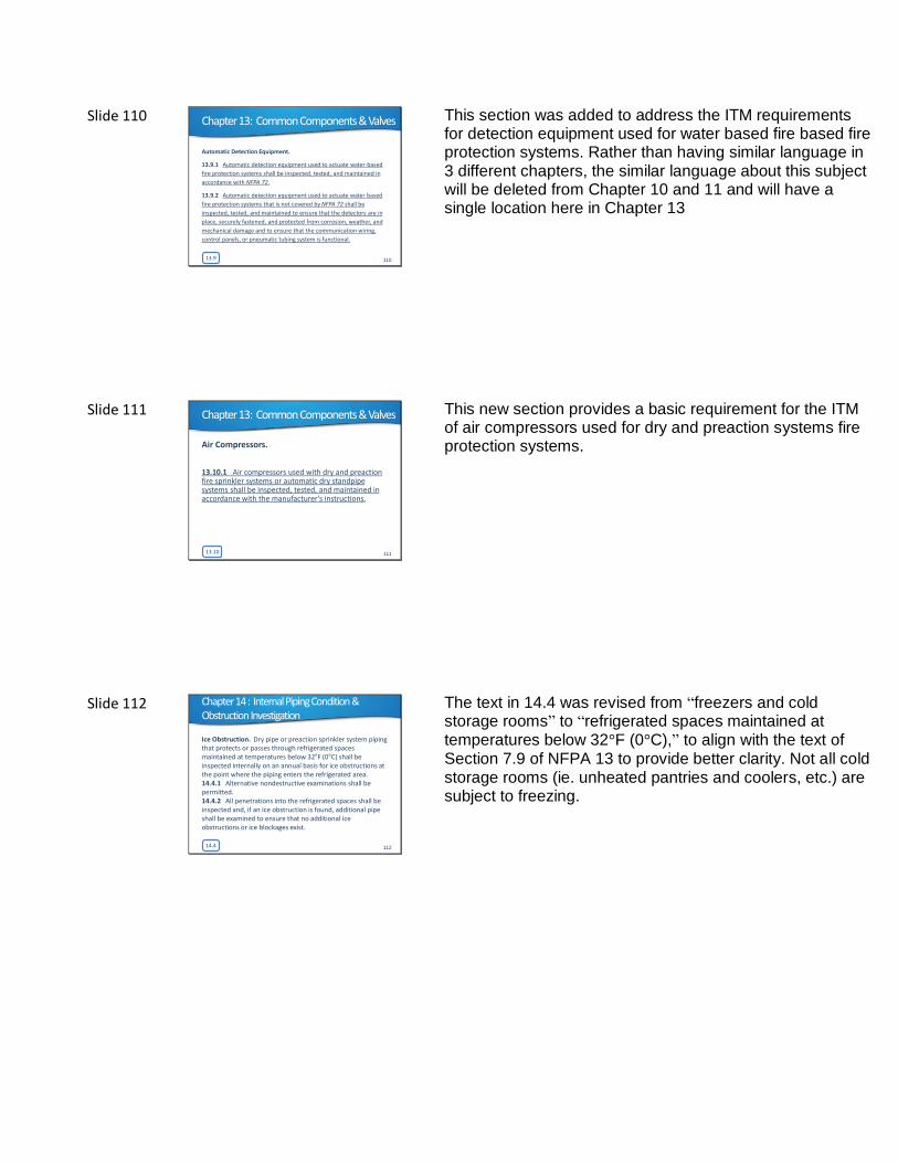
The impaired equipment shall include, but shall not be limited to, the following:
(1) Sprinkler systems(2) Standpipe systems(3) Fire hose systems(4) Underground fire service mains(5) Fire pumps(6) Water storage tanks(7) Water spray fixed systems(8) Foam-water sprinkler systems(9) Water mist systems(10) Fire service control valves(11) Water supply
15.4.2 113
Chapter 15: Impairments
Water supply was added as piece of equipment that can be impaired.
Slide 114
16.3 114
Chapter 16: Special Requirements from Other NFPA Documents
Aircraft Hangers.
16.3.1 The requirements in this section shall only apply to water-based fire
protection systems in aircraft hangars installed in accordance with NFPA 409.
16.3.2 Inspection, testing, and maintenance of water-based fire protection
systems in aircraft hangars shall be performed in accordance with this
standard as modified by the requirements itemized in Table 16.3.2.
[409:11.1.1]
• Added new Table 16.3.2 Inspection and Testing of Water-Based Fire
Protection Systems in Aircraft Hangars [409:Table 11.1.1]
This new section has been added to provide ITM requirements of water based fire protection systems that are found in NFPA 409.
Slide 115
Q & A
Bob Caputo, CFPS, CETFire & Life Safety America
bgcaputo@ flsamerica.com