Embed Size (px)
Citation preview
Next100 Pressure Vessel - User’s Design Specification(DRAFT 3)
Derek Shuman1, Sara Carcel2 A. Martınez2
NEXT Collaboration
1Lawrence Berkeley National Laboratory (LBNL), Berkeley CA, USA2Instituto de Fısica Corpuscular (IFIC), CSIC, Univ. de Valencia, Valencia, Spain,
2 April 2012
Contents
1 Introduction 2
2 Purpose 2
3 Introductory Requirements Description 2
4 Parties to the Contract 4
4.1 Collaboration . . . . . . . . . . . . . . . . . . . . . . . . . . . . . . . . . . . . . . . . 4
4.2 Manufacturer . . . . . . . . . . . . . . . . . . . . . . . . . . . . . . . . . . . . . . . . 4
4.3 Certification Authority . . . . . . . . . . . . . . . . . . . . . . . . . . . . . . . . . . . 4
4.4 Inspector . . . . . . . . . . . . . . . . . . . . . . . . . . . . . . . . . . . . . . . . . . . 4
5 Scope of Contract 4
6 Responsibilities 5
6.1 Manufacturer . . . . . . . . . . . . . . . . . . . . . . . . . . . . . . . . . . . . . . . . 5
6.1.1 Accreditation . . . . . . . . . . . . . . . . . . . . . . . . . . . . . . . . . . . . 5
6.1.2 Material Use Planning . . . . . . . . . . . . . . . . . . . . . . . . . . . . . . . 5
6.1.3 Final Design . . . . . . . . . . . . . . . . . . . . . . . . . . . . . . . . . . . . . 5
6.1.4 Fabrication Plan . . . . . . . . . . . . . . . . . . . . . . . . . . . . . . . . . . 6
6.1.5 Collaboration Access . . . . . . . . . . . . . . . . . . . . . . . . . . . . . . . . 6
6.2 Collaboration . . . . . . . . . . . . . . . . . . . . . . . . . . . . . . . . . . . . . . . . 6
7 ASME User Design Specification 6
8 Drawings 13
9 Appendix 29
9.1 Calculations . . . . . . . . . . . . . . . . . . . . . . . . . . . . . . . . . . . . . . . . . 29
1
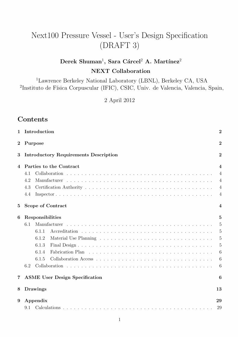
Figure 1: Detector Cross section
1 Introduction
This document is a User’s Design Specification for a pressure vessel to be used in a neutrino physicsexperiment called NEXT-100. Drawings presented here are not to be considered final. ProspectiveManufacturers are encouraged to provide feedback on the design, and details of fabrication, as wellas preliminary cost and schedule estimates.
2 Purpose
The NEXT Collaboration is a group of physicists and engineers affiliated with Institute of ParticlePhysics/ University of Valencia, (IFIC) (principal institution), LBNL, and many others. The NEXT-100 experiment proposal is funded by this collaboration to build a detector to look for a phenomenoncalled neutrinoless double beta decay. The experiment requires a pressure vessel, to be used for gascontainment, and additionally as the housing and support for a neutrino detector installed inside.Figure 1, below, shows a cross section of the detector inside the pressure vessel. This pressure vesselis the subject of this Specification.
3 Introductory Requirements Description
The pressure vessel has the following general requirements:
1. Size, Shape, Orientation: 1.360m inner diameter x 2.286m inside length, cylindrical main vesselsection with detachable torispheric heads on each end, vessel axis horizontal, with two saddle
2
supports welded to main vessel shell. Welded-in nozzles on both the main vessel and the headsextend the overall size to 2.8m overall length x 1.5m high.
2. Assembly Configuration: 3 parts, a main cylindrical vessel with bolted flange connectionsto torispheric heads on each end. Flanges are flat faced with double O-rings or, possiblya Helicoflex C-ring/O-ring combination, to provide pressure and vacuum seal on both mainflanges and on nozzle flanges.
3. Material: Main Vessel and Heads, shells, nozzles and flanges: Stainless Steel, 316Ti plate (UNSS31635, EN 1.4571) per ASME specification SA-240 or (EU) equivalent; main flange bolting:Inconel 718 ASME specification grade SB-637 (UNS N07718) or (EU) equivalent.
4. Fluid: gaseous xenon (primary), argon, neon, nitrogen, dry air, with small amounts of CF4,CH4, H2, at room temperature to 50C (negligible corrosive, flammable or toxic hazard).
5. Design Pressure Range : -1.5 atm to 15.4 barg (16.4 bara)
6. Leak Tightness: (1X10⁻⁶ torr*L/sec
7. Design Standard: ASME Pressure Vessel Code section VIII, division 1, using full weld effi-ciency (fully radiographed double and full penetration welds required). Other design standardsallowable in Canfranc, Spain may be used. Note that although the requirement for a User’sDesign Specification is only required for Pressure Vessels designed under ASME section VIIIdivision 2 rules, we regard this as an essential controlling document for the vessel.
8. Low residual background radioactivity; additional material and process screening, over andabove that required by ASME Pressure Vessel Code, or equivalent, will be performed by theCollaboration; full cooperation of Manufacturer is required. Nominal design may be impactedby (now pending) test results.
9. Internal detector components will be supported on internal flanges on the vessel (on both maincylindrical and on torispheric heads), and nozzle flanges. Total weight of detector inside vesseldoes not exceed 13000 kg (13 metric tons).
These requirements and others are fully detailed in the Requirements section below. This includesrequirements outlined in ASME PV code sec VIII, division 2, part 2.2.2 ”User’s Design Specification”.We continue with the general description:
There are two unique and noteworthy aspects of this vessel; the first is a radiopurity requirementand, the second to a lesser extent, the need to mount internal components. The detector insidethe vessel is highly sensitive to radiation from trace amounts of uranium (U) and thorium (Th).Austenitic stainless steel alloys contain uranium and thorium in trace amounts, from several partsper trillion (ppt) to hundreds of parts per million (ppm), only the lower levels are acceptable to us.316Ti (1.4571) has been well characterized by others and found to typically show acceptably lowlevels; this is the reason we are specifying its use, even though other alloys may also be acceptable.
To assure sufficient radiopurity of materials, the Collaboration will require samples (several kg.each) from all raw material lots (bar, plate, tubing, forging ends, etc. ) in order to perform back-ground radiation counts prior to the material be accepted for fabrication, These counts take 1 montheach to perform and we can only perform 2 simultaneous sample measurements at one time, soadequate material procurement scheduling is required.
Regarding manufacturing, thoriated TIG welding electrodes, and guns that have been used withsuch electrodes must not be used. Ceriated, lanthanated, yttriated, or plain tungsten electrodes areacceptable. Special cleaning procedures for material preparation are required, and may be subjectto testing by the Collaboration and may be modified
The pressure vessel also serves to support the detector inside. The detector contains a largeamount of radiation shielding, in the form of precision machined copper bars and plates, approx.12000 kg of copper in all. The vessel to head flanges incorporate internal flanges for mounting ofboth this copper shielding and the detector components. As such all final machining on the mustbe performed only after a full stress relief anneal is performed after welding operations. Head to
3
vessel flanges are nominally bolted; a flat faced flange design is used having 2 O-rings for seals, witha vacuum sense port in between them to detect leakage. The inner groove will be compatible, iffeasible, with a Helicoflex gasket, loaded to its Y1 unit force. Manufacture must only demonstrateproper sealing performance using elastomer O-ring seals in both grooves. Manufacturer is invitedoffer some details as to preferred fabrication details before final specification is issued.
4 Parties to the Contract
Henceforth in this Document, the parties to the contract are listed and defined as follows:
4.1 Collaboration
The Collaboration is headed by Dr. J.J. Gomez, IFIC. The lead mechanical engineer for the pressurevessel is Derek Shuman, LBNL, with assistance from mechanical engineers: Sara Carcel and AlbertoMartınez (IFIC). Sara will be the prime contact person overseeing fabrication, as of this writing.
4.2 Manufacturer
This is the primary firm contracted with the Collaboration to perform or coordinated the design,fabrication, and testing. Subcontractors are not included, however, the rights of inspection negotiatedbetween the Collaboration and the Manufacturer must be extended to apply to all subcontractors.
4.3 Certification Authority
This is an independent Certification Authority contracted to certify this document for completenessand correctness prior to the commencement of fabrication, and also to certify the Manufacturer’sDesign Report prior to the acceptance of the vessel by the Collaboration.
4.4 Inspector
This is a qualified person provided by the Certification Authority to perform inspections of all aspectsof the design, fabrications and testing, in order to verify that the vessel has been designed, fabricatedand tested in full compliance with the appropriate pressure vessel code.
5 Scope of Contract
Manufacturer is to supply, at a minimum, the complete vessel, in a clean condition compatible withhigh vacuum testing, complete with all flange bolts, nuts, washers, and all blank-off plates used forhydrostatic testing. Optionally, the Manufacturer may additionally supply the nozzle extensions, andother internal parts of the detector. Excess unused plate material shall be returned to Collaboration,if feasible. The Collaboration will supply the pressure relief devices. Here is a detailed list:
1. (1) main vessel, per LBNL drawing 26K590A
2. (2) torispheric heads per LBNL drawing 26K591A
3. (300) studs, per LBNL drawing 26K593A
4. (300) hex nuts, per LBNL drawing 26K597A
5. (600) washers, per LBNL drawing 26K598A
4
6. (4) O-rings, nitrile, 5mm x 1320mm ID, Trelleborg Fleximold splice-free suggested
7. (4) O-rings, nitrile, 3mm x 1460mm ID, Trelleborg Fleximold splice-free suggested
8. (16) O-rings, nitrile, 3mm x 90mm ID
9. (16) O-rings, nitrile, 3mm x 110mm ID
10. (4) O-rings, nitrile, 3mm x 65mm ID
11. (4) O-rings, nitrile, 3mm x 70mm ID
12. (12) O-rings, nitrile, 3mm x 35mm ID
13. (12) O-rings, nitrile, 2.5mm x 50mm ID
14. (2) heads per LBNL drawing 26K591A
15. (9) Nozzle Cover Plates, DN100 per LBNL drawing 26K594A
16. (3) Nozzle Cover Plates, DN75 per LBNL drawing 26K595A
17. (7) Nozzle Cover Plates, DN40 per LBNL drawing 26K596A
18. hardware (316 SS, silver plated) to attach the above 3 items to vessel flanges
19. Manufacturers Design Report, in both Spanish and English
6 Responsibilities
6.1 Manufacturer
6.1.1 Accreditation
Manufacturer, and all subcontractors, is required to be fully certified under ASME rules, or Europeanequivalent, to design, fabricate , inspect, and test pressure vessels. Welders and NDT inspectors, inparticular, shall be certified to perform all operations required.
6.1.2 Material Use Planning
Manufacturer is to use materials provided by the Collaboration to fabricate the vessel, unless otherarrangement is made. Manufacturer is required to approve any materials provided by the Collabora-tion with regards to fitness of use. Manufacturer must request any certifications, samples needed fortesting. Manufacturer is to specify the range of raw material sizes, and the amounts of each neededto fabricate the vessel All materials and equipment used, that are supplied by the Manufacturer, aresubject to approval by the Collaboration, both raw materials that will be part of the vessel, and allother materials and equipment used in the manufacturing process.
6.1.3 Final Design
Manufacturer is responsible for the pressure integrity of the vessel and is required to perform allnecessary calculations and analyses, as Manufacturer sees fit. Detailed preliminary calculations areprovided by the Collaboration, in the Appendix, as a convenience, and to justify the dimensions of thevessel presented here in this Specification, however manufacturer is ultimately responsible for pressureintegrity and sufficiency of design. Manufacturer may propose changes to the design, however thesemust be approved by the Collaboration. The design presented here is performed according to therules of ASME section VIII, division 1, with full weld efficiency, which is required in the final design.This requires full penetration double welds on the major welds plus a full radiographic inspection.Other codes that are acceptable in the Jurisdiction of Canfranc, Spain are acceptable in part, or infull, as allowed by the codes themselves.
5
6.1.4 Fabrication Plan
Manufacturer is to submit a detailed fabrication plan to Collaboration for approval prior to com-mencement of fabrication, describing the sequence of operations to be used in fabricating and testingthe vessel. These shall include (but not be limited to) the following:
1. Main Cylindrical Vessel: shell forming and welding sequence, all dimensions of shell sections,rolling methods, edge preparations and cleaning, welding procedures and equipment, interme-diate heat treatments, and inspections.
2. Torispheric Head: shell forming, rolling methods, edge preparations, welding procedures andequipment, intermediate heat treatments, and inspections.
3. Head to Vessel Flange fabrication sequence, all dimensions of flange sections, edge preparations,welding procedures, intermediate heat treatments and inspections.
4. Flange to Shell Weld joint design
6.1.5 Collaboration Access
Manufacturer and all subcontractors are to allow visits and inspections by members of theCollaboration during any and all parts of the fabrication, upon request. This is in addition theaccess granted to the Inspector of the Certifying Authority.
6.2 Collaboration
Collaboration is responsible for finding and securing the required material in timely manner prior toscheduling construction. The Collaboration is responsible for timely radiopurity testing of materialsamples from lots. Each of these measurements can take up to one month to complete. A scheduleof radiopurity measurements will be drafted once the manufacturing process is fully known.
7 ASME User Design Specification
2.2.2.1 ASME required specifications
a) Installation Site
1) Location - Installed location - Canfranc Spain, inside Canfranc Under Ground Laboratory (LSC)in Hall 1. Vessel may be staged temporarily at some other location, perhaps for pressure testing,and/or for trial assembly of detector. This location will be either at IFIC in Valencia, or perhapsat University of Zaragoza, or some other location in Spain.
2) Jurisdictional Authority All that are required for the locations listed above
3) Environmental conditions
i) Wind loads - None
ii) Seismic Design Loads - 1m/s2 (0.1g) maximum vertical (over static gravity); 2 m/s2 max-imum horizontal acceleration. Vessel will be mounted on a shock isolating platform, and willbe elevated above the hall floor by 1.2m
iii) Snow Loads - None
6
iv) Lowest one day mean temperature- 10C . Note - remote possibility exists of cryogen spillunderneath pressure vessel, with temperature unknown. Cryogenic liquid is not expected tocontact vessel, as the vessel will be mounted on a platform at least 1.5 m above the mainhall floor, and a total cryogenic liquid spill will result in at most a few cm of liquid height onfloor. Nevertheless, vessel will be immediately vented to 0 barg upon receiving a fault signalindicating a cryogen spill in the LSC hall.
b) Vessel Identification
1) Vessel Number - ”NEXT100-PV1”
2) Fluids - gaseous xenon (primary), argon, neon, nitrogen, dry air, with small amounts of CF4,CH4, H2 (<5%), all held at room temperature to 50C (negligible corrosive, flammable or toxichazard). No liquids will be introduced into the vessel, other than cleaning, in the disassembledcondition or perhaps in an assembled condition, unpressurized. Although not presently planned,the vessel may eventually be immersed in a fluid bath, of either ultrapure water, or scintillatorfluid (as yet unknown), with the vessel in either the pressurized or vacuum condition. Maximumfluid pressure of this bath will be, at the lowest point of the vessel no higher that 0.35 barg,from hydrostatic head only, the water or scintillating fluid being at atmospheric pressure. Thereshould be no corrosion allowance made in the design for this possible future use; adjustment willbe made to operating pressure if needed.
c) Vessel Configuration and Controlling Dimensions - The vessel will be oriented with its axis ofrevolution in the horizontal direction. LBNL Drawing number 26K589A shows the assembled vesselwith controlling dimensions, some of which are listed below:
Inside Diameter, Vessel and Head Shells 1360 mmInside Length, on Centerline Axis, including Heads 2286 mm
Length, Main Cylindrical Vessel 1600 mmTorispheric Head Inner Crown Radius (Rc=1.0D, Kloepper) 1360 mm
Torispheric Head Inner Knuckle Radius (Rk=0.1D, Kloepper) 136 mmCenter axis height above floor(including support pads) 800mm
Table 1: Required Geometric Values
d) Design Features
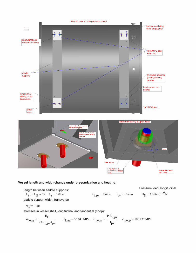
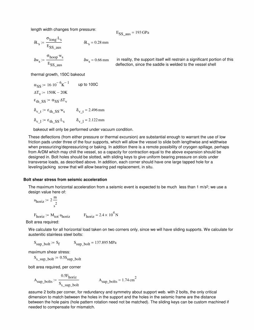
1) Supports - The vessel shall be designed with saddle supports welded to the main cylindricalvessel. These supports shall be sufficient to support the weight of the pressure vessel, withall internal components and fluids, for static gravity plus the maximum seismic acceleration,described below. The supports shall be designed to accommodate expansion and contraction ofthe vessel, from both pressure/vacuum and from temperature excursions. The vessel must returnto the same position upon returning to normal operating temperature. The proposed designutilizes low friction polymer bearing pads in a 2D kinematic support arrangement (shown in theCalculations); Manufacturer may propose alternate methods or materials. The vessel may belifted with slings while empty. It is not foreseen that the vessel will be lifted with the internalcopper shielding inside, however jacking screws on the support feet are provide for leveling withthe copper inside. The Appendix contains a set of illustrations detailing the proposed design.
The torispheric heads are not required to have lifting lugs welded to them, though Manufac-turer may elect to add these, with prior approval. If lugs are added, they must be designed forthe entire mass of the head plus its internal copper disk (2500 kg). The collaboration will beusing specially designed lift fixtures to handle the heads; these attach to the head using various
7
combinations of the flange bolt (clearance) holes. Some of these clearance holes will be threadedto accept certain lift fixture mounting bolts. See section on Loads below for further description.
2) Flanges - The main cylindrical vessel flanges incorporate a step of 1mm to provide a recessedgasket sealing surface for protection against damage. Simple flat covers may then be used forservicing conditions. Care must still be taken during final machining and later operations to placethe flange surface on a very clean surface with no chips or debris.
The head flanges contain 2 O-ring grooves, the inside a pressure seal and the outside a vacuumseal. Four drilled holes (vacuum ports) located between the lands allow vacuum checking for O-ring permeation or leakage. A shallow groove at this radial location is incorporated to improvegas conductance to the vacuum ports.
A ”shear lip” is incorporated in the ID of the head flange which fits inside the Vessel ID so asto prevent the head from sliding downward in case the flange studs somehow come loose or thejoint opens under pressure (not likely to occur), though very little extra stud tension is neededto support the head vertically by friction. The shear lip may also reduce light leakage throughthe O-rings, should this be a problem.
e) Design Conditions
Internal Pressure, MPa (g) External Pressure, MPa (g)1.54 0.15
Table 2: Design Pressures,(gauge)
f) Operating Conditions
1) Maximum Operating Pressure (MOP) - 14.0 barg
2) Maximum Allowable Working Pressure (MAWP) - 15.4 barg
3) Operating Temperature - 15C-30C. Temperature may rise to 150C under a vacuum (-1.0barg) condition, but not under pressure condition.
4) Fluid Transients and Flow - A typical operating cycle, following any condition requiring thevessel to be opened, is as follows:
1. Vessel will be pulled to vacuum condition and held for several days. Vessel may be heated to50C during this operation.
2. Xenon gas will then be introduced at a slow fill rate, no less than 10 min. to fully pressurize.
3. Xenon gas will then be circulated at 200 SLPM through the vessel/ purifier circuit. Detectorwill be operated during this time, continuously, without interruption of flow or pressure, for aslong as possible.
Should the detector need a repair which requires removing at least one of the heads or nozzleattachments, the following sequence of operations is performed:
1. Vessel will be vented by opening a valve connecting to a cryogenic recovery cylinder, depres-surization is expected to take at least 30 minutes. Pressure will be reduced to less than 1torr.
2. Vessel will be filled with clean dry air to 0.01-0.1 barg, then vented to atmosphere.
3. The head assembly fixture will be assembled to the floor.
4. Head to flange studs occupying the threaded holes in the head are be removed
8
5. The head assembly fixture is then aligned to closely mate with the head flange and is thenbolted to the head
6. The remainder of the head to vessel flange studs are removed to allow head to be moved awayfrom the vessel, on the fixture rails, by a distance of 1m
7. A second lift fixture is then bolted to the head using a number of holes at the top; this liftfixture provides a single lift point for attachment to a crane hook, with the lift point over thecenter of gravity of the head/internal copper shield disk assembly. See section on Loads belowfor further description.
Under a possible emergency condition defined as an abnormally high pressure drop rate occurringduring normal operation, the vessel will be vented in approximately 10 sec. to the large vacuumtank, in order to minimize loss of the xenon into the LSC Hall. This will be accomplished by usingat least one remote operated active vent valve that will open fully upon receiving a controllersignal. Figure 1 shows the location of this valve. This valve is in parallel with the main pressurerelief valve (not shown). The active vent valve will be a straight-through design, so that reactionforce does not exert a force transverse to the nozzle axis. However, the possibility exists that aright angle valve might mistakenly be substituted, and so the auxiliary nozzles on each head mustbe designed to withstand a moment caused by the reaction force from this valve. The maximumflow rate will be 25 kg/sec (Xe). The reaction force associated with this flow (xenon) is 3500N. The vent valve will be located on the end of a nozzle extension that is 58cm long; thus amaximum moment of 2300 N*m may be applied to the nozzle to head weld; this is the designrequirement for weld and nozzle sufficiency. The relief valve for fire condition or failed regulatoris much lower flow and may be a right angle valve. It may be located next to the active fast ventvalve, in parallel flow, or may be located on the tracking plane head auxiliary nozzle (right sideof fig. 1).
g) Design Fatigue Life - The vessel is estimated to undergo not more than 200 full pressure cycles, atmost (including head removals) during its lifetime. Each vessel head is not expected to be removedmore than 50 times. Pressure will remain static for each pressure cycle; i.e. pressure is not variedduring vessel operation, only during filling and venting. Some pressure cycles will be less than fullMOP. Pressure change rate under typical operating conditions will be low, less than 0.001 bar/sec.There will be a few rapid depressurization events, of maximum 2 bar/sec using a remote actuatedvent valve; not more than 10 of these cycles are estimated to occur, primarily from testing.
h) Materials of Construction
1) Vessel - Stainless Steel plate, 316Ti (UNS S31635, EN 1.4571) per ASME SA-240 specificationor equivalent: all vessel shells, nozzles and head-to vessel flanges shall be made from plate unlessother forms are allowable, under acceptable pressure vessel codes other than ASME sec VIII, div.1. Material will be provided by the Collaboration.
2) Bolting - Inconel 718 (UNS N77180) to ASME SB-637 standard or equivalent, studs, nuts andwashers. Material will be provided by the Collaboration.
i) Flange Seals
1) Main Head to Vessel Flanges- O-rings: butyl, nitrile, possibly PCTFE or PTFE ((nozzleflanges only), or special low force Helicoflex (type HN200), aluminum jacket. Main head tovessel flanges will be double O-ring sealed, the larger cross section O-ring for pressure, the outer,smaller cross section for vacuum. The annulus between them will incorporate a sense port forleak checking the O-rings.
2) Nozzle flanges All nozzle flanges are sized to ASME standards (section VIII, div 1, Appendix Y)using standard CF knife edge flange bolt patterns. This is to allow use of pressure rated or tested
9
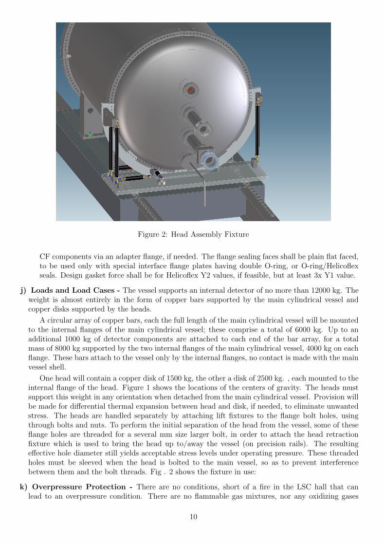
Figure 2: Head Assembly Fixture
CF components via an adapter flange, if needed. The flange sealing faces shall be plain flat faced,to be used only with special interface flange plates having double O-ring, or O-ring/Helicoflexseals. Design gasket force shall be for Helicoflex Y2 values, if feasible, but at least 3x Y1 value.
j) Loads and Load Cases - The vessel supports an internal detector of no more than 12000 kg. Theweight is almost entirely in the form of copper bars supported by the main cylindrical vessel andcopper disks supported by the heads.
A circular array of copper bars, each the full length of the main cylindrical vessel will be mountedto the internal flanges of the main cylindrical vessel; these comprise a total of 6000 kg. Up to anadditional 1000 kg of detector components are attached to each end of the bar array, for a totalmass of 8000 kg supported by the two internal flanges of the main cylindrical vessel, 4000 kg on eachflange. These bars attach to the vessel only by the internal flanges, no contact is made with the mainvessel shell.
One head will contain a copper disk of 1500 kg, the other a disk of 2500 kg. , each mounted to theinternal flange of the head. Figure 1 shows the locations of the centers of gravity. The heads mustsupport this weight in any orientation when detached from the main cylindrical vessel. Provision willbe made for differential thermal expansion between head and disk, if needed, to eliminate unwantedstress. The heads are handled separately by attaching lift fixtures to the flange bolt holes, usingthrough bolts and nuts. To perform the initial separation of the head from the vessel, some of theseflange holes are threaded for a several mm size larger bolt, in order to attach the head retractionfixture which is used to bring the head up to/away the vessel (on precision rails). The resultingeffective hole diameter still yields acceptable stress levels under operating pressure. These threadedholes must be sleeved when the head is bolted to the main vessel, so as to prevent interferencebetween them and the bolt threads. Fig . 2 shows the fixture in use:
k) Overpressure Protection - There are no conditions, short of a fire in the LSC hall that canlead to an overpressure condition. There are no flammable gas mixtures, nor any oxidizing gases
10
inside the vessel at any time when it is closed (dry air may be circulated through the vessel whenheads are removed to allow people to work inside). There are only metals, ceramics and commonplastic materials such as polyethylene, PEEK, PTFE, PMMA, epoxy, etc. inside the vessel, Thereare electrical components inside generating no more than 1 kW of heat dissipation, these will beactively cooled with water cooling circuits, either inside the vessel, or outside, using either the xenongas or the vessel as a heat transfer surface (10C maximum allowable temperature rise above 20Cambient; 30C actual temp). Fast vent capability is incorporated solely for the purpose of minimizinggas loss in the case of an unexpected leak, as the xenon gas is very expensive and the LSC Hallis an enclosed space. Fast venting, in an emergency, will be done by actuating a remote operatedvent valve leading directly to a large evacuated recovery cylinder of 20-30 m3 (thus reducing pressureto <1 bara). The high cost of the xenon, and the enclosed underground cavern combined with thepotentially dangerous anesthetic properties of xenon gas preclude venting directly to atmosphere.There will be two relief devices, one passive and one active:
1) Passive: Pilot operated reclosable relief valve, back pressure insensitive - set to 100%MAWP),valve sized for fire or malfunctioning regulator.
2) Pilot operated servo vent valve, 65 mm vent dia. - Set to actuate only upon emergency signal(indicating a substantial leak), at any pressure, for fast vent to vacuum tank. maximum dischargerate is, for xenon at 15 bara 25 kg/sec. This valve will be a straight through design, to eliminatetorque on the nozzle from reaction (it may be located at the end of a 60 cm long nozzle extension).However the nozzle must be designed to withstand a reaction force directed at a right angle tothe nozzle axis, as described above
2.2.2.2 Additional Specifications
a) Material Supplied by Collaboration -
As part of the radiopurity requirement below, the Collaboration will find, measure samples andpurchase all consumable materials used for fabrication, including plate and welding wire. These shallbe purchased and secured prior to commencement of fabrication. Manufacturer shall submit a list ofmaterials to purchase which must include all necessary allowances for trimming and finish machining.
b) Minimum Thickness Design -
This requirement is driven by the radiopurity requirements below; the proposed design assumes aweld efficiency of 1.0 for any division 1 calculations and thus will require a full radiographic inspectionof all pressure bearing welds. Welds in category A and B will be required to be full penetration doublewelds.
The use of a large number of flange bolts and the specification for using fine thread Inconel 718bolting material follows, this minimizes flange outer diameter; bolt holes will need higher than usualdimensional accuracy and must not be rough drilled prior to final solution annealing.
c) Use of Plate Stock for Flanges -
The flat faced flange design used is designed to div. 1 rules, Appendix Y. Div. 1 allows flangesto be made from plate if no hub is present (which is the case in this design). Plate stock is not idealfor machining into flanges, and there is some possibility that leakage paths from laminar flaws insidethe plate may compromise the vacuum tightness of the vessel. 316Ti plate is the only permissibleform in Div. 1. and the Collaboration is supplying 50mm stock which precludes rolling and weldinginto a ring. Manufacturer is cautioned to perform any necessary tests such as X-ray, ultrasound, orhelium leak checking of samples, above that which are required under ASME code, so as to assurevacuum tightness as specified in the Specification.
d) Radiopurity Assurance -
11
In order to assure that all materials used to fabricate the vessel are of high radiopurity and donot become contaminated in the fabrication process, there will be additional material checks of bothraw material, and of samples from each fabrication process along the way. Every effort will be madeto determine the scope of these checks. Therefore Manufacturer has a responsibility to disclose anyand all fabrication processes to be used, both prior to start of fabrication, and through fabrication,inspection and testing. Each material sample test takes 3 weeks to perform, so Manufacturer mustbe forthcoming in disclosures. Tests may be performed on the following items:
1) Possible Tests on Materials
i) ends from all raw plate used to fabricate vessel shells, flanges, attachments and supports
ii) ends from all finished rollings and spinnings after welding, cylinder and both heads
iii) ends from all bar, pipe and tube stock used for nozzles and nozzle flanges
iv) ends or samples from all bar stock used to fabricate flange bolts and nuts, if applicable
2) Procedures -
i) All welding shall be of the gas tungsten arc (GTAW) in accordance with ASME or equivalentprocedures.
ii) The welding will be done by ASME or equivalent qualified welders, as per ASME or equivalentrequirements.
iii) Filler for welding: 316Ti commercial use filler. Filler material samples shall be submittedto the Collaboration for radiopurity measurement; if unacceptably contaminated, filler metalmay be made from from the supplied plate stock.
iv) All parts shall be thoroughly cleaned prior to assembly and welding for welding per thefollowing process:
a. All supplies and tools to be used are subject to approval by the Collaboration. Manufac-turer shall submit a list of list of tools and machinery used for cleaning, to the Collaborationprior to use.
b. The bending rolls shall be cleaned before the bending operation with an appropriate surfacewith clean rags.
c. The welding should be done in a clean enclosed space specific to stainless steel, to preventinclusion of iron or other contaminants.
d. Filler must be cleaned and dried prior to use, per ASME or equivalent standards.
e. The assembly/welding area should be isolated and clean, without contamination of otherwork.
f. Thoriated electrodes, as well as guns and shields previously used with thoriated electrodesmust NOT be used. Plain tungsten (WP EN 26 848, 99.8% minimum tungsten, green),ceriated, yttriated or lanthanated electrodes are acceptable. Shielding gas is argon with aminimum purity of 99.99%, group I, IN 439)
e) Precision Tolerances - To assure that vessel is fabricated on time, and to avoid unnecessaryrework, it is imperative to follow a well thought out sequence of fabrications. Manufacturer isto submit a fabrication plan to Collaboration for approval, as mentioned elsewhere. Fabricationrequirements:
12
1) All welding to be performed with flanges in rough machined condition. No flange bolt holes mustbe present in head to vessel flanges before full solution anneal, below. Nozzle flanges may beprewelded to nozzles, finish machined, then welded to main vessel and heads after main vesselsolution anneal below.
2) Torispheric head shells are recommended be in fully solution annealed prior to welding to headflanges.
3) Main cylindrical vessel shell is recommended to be fully solution annealed prior to welding tovessel flanges.
4) Vessel and heads shall be stress relieved to 85% minimum, or better, after welding and prior tofinal machining; a full solution anneal is recommended (1050C maximum) for 2 hr minimum,followed by a slow cooldown period of not less than 8 hrs (4 hrs/25mm of section); vessel andheads shall be placed with axes vertical on flat surfaces, in a free unstressed, and unconstrainedcondition for the duration of this this operation, with full air circulation (to avoid formation ofMoO3). If annealing is performed as a bright anneal process, argon or full vacuum must be used;hydrogen shall not be used.
5) Saddle supports are to be fabricated separately, and solution annealed as above prior to finalmachining and welding to main cylindrical vessel.
6) Nozzles and saddle supports may be welded to vessel and heads after final machining of mainflanges, if Manufacturer is confident final tolerances on drawing can be met.
8 Drawings
13
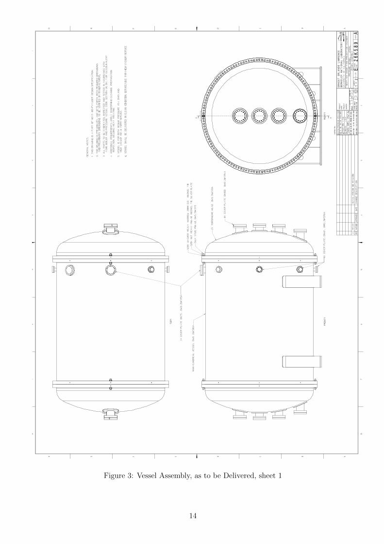
Figure 3: Vessel Assembly, as to be Delivered, sheet 1
14
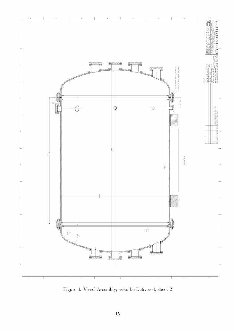
Figure 4: Vessel Assembly, as to be Delivered, sheet 2
15
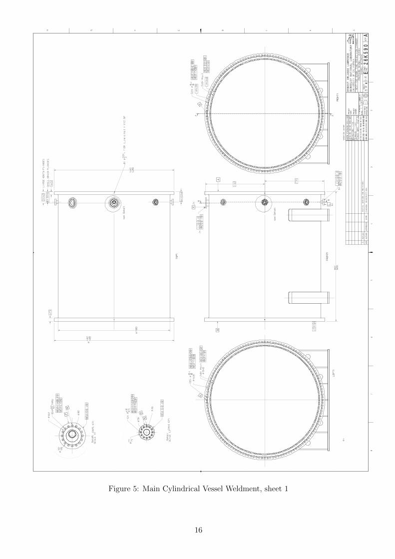
Figure 5: Main Cylindrical Vessel Weldment, sheet 1
16
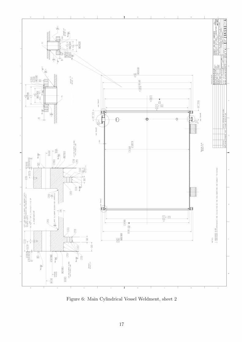
Figure 6: Main Cylindrical Vessel Weldment, sheet 2
17
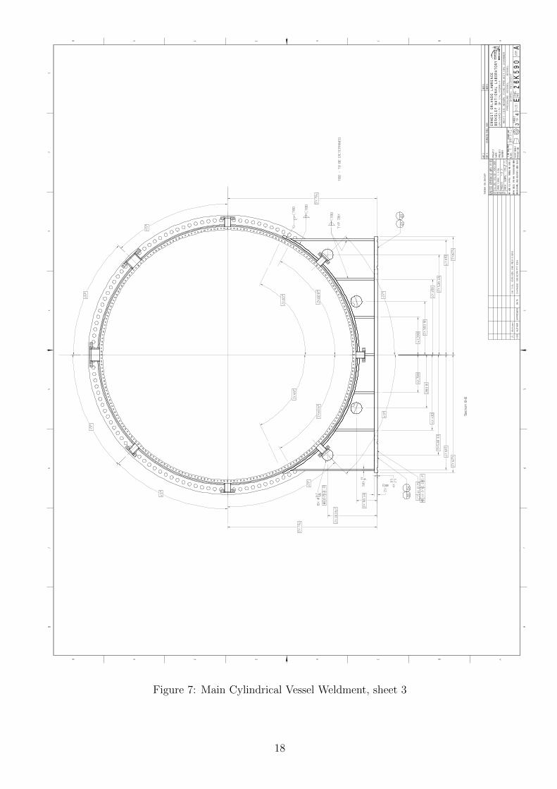
Figure 7: Main Cylindrical Vessel Weldment, sheet 3
18
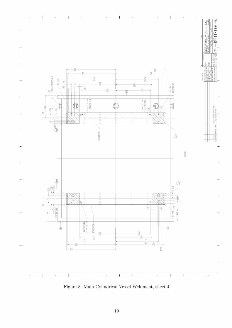
Figure 8: Main Cylindrical Vessel Weldment, sheet 4
19
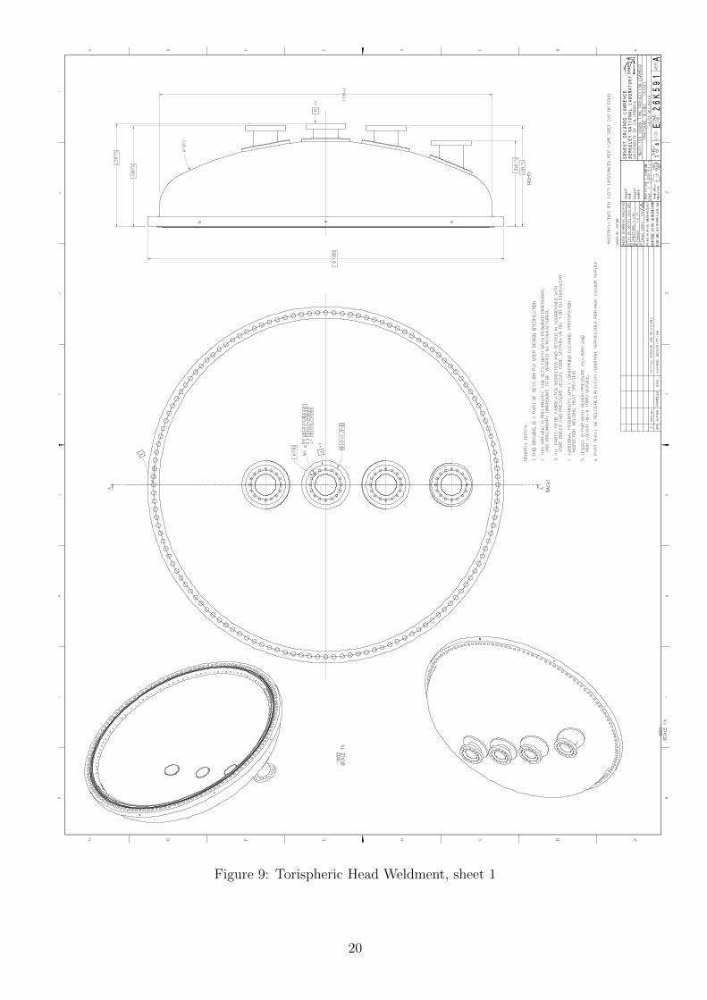
Figure 9: Torispheric Head Weldment, sheet 1
20
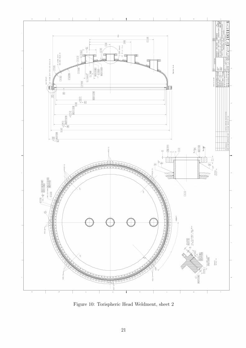
Figure 10: Torispheric Head Weldment, sheet 2
21
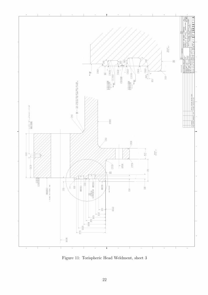
Figure 11: Torispheric Head Weldment, sheet 3
22
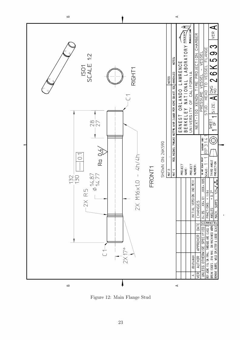
Figure 12: Main Flange Stud
23
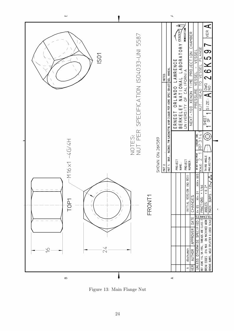
Figure 13: Main Flange Nut
24
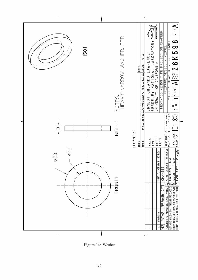
Figure 14: Washer
25
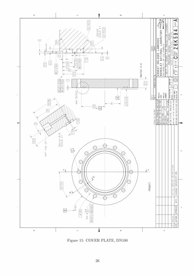
Figure 15: COVER PLATE, DN100
26
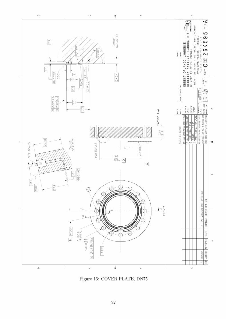
Figure 16: COVER PLATE, DN75
27
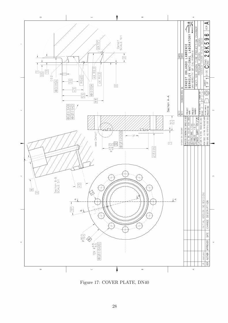
Figure 17: COVER PLATE, DN40
28
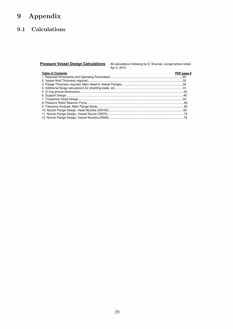
9 Appendix
9.1 Calculations
Pressure Vessel Design Calculations All calculations following by D. Shuman, except where noted.
Apr 2, 2012
Table of Contents PDF page #
1. Required Dimensions and Operating Parameters.....................................................................................30
2. Vessel Wall Thickness required................................................................................................................32
3. Flange Thickness required, Main Head to Vessel Flanges........................................................................34
4. Additional flange calculations for shielding loads, etc................................................................................41
5. O-ring groove dimensions..........................................................................................................................43
6. Support Design..........................................................................................................................................45
7. Torispheric Head Design...........................................................................................................................54
8. Pressure Relief Reaction Force..................................................................................................................60
9. Tolerance Analysis, Main Flange Studs......................................................................................................62
10. Nozzle Flange Design, Head Nozzles (DN100)........................................................................................65
11. Nozzle Flange Design, Vessel Nozzle (DN75)..........................................................................................72
12. Nozzle Flange Design, Vessel Nozzles.(DN40)........................................................................................78
29
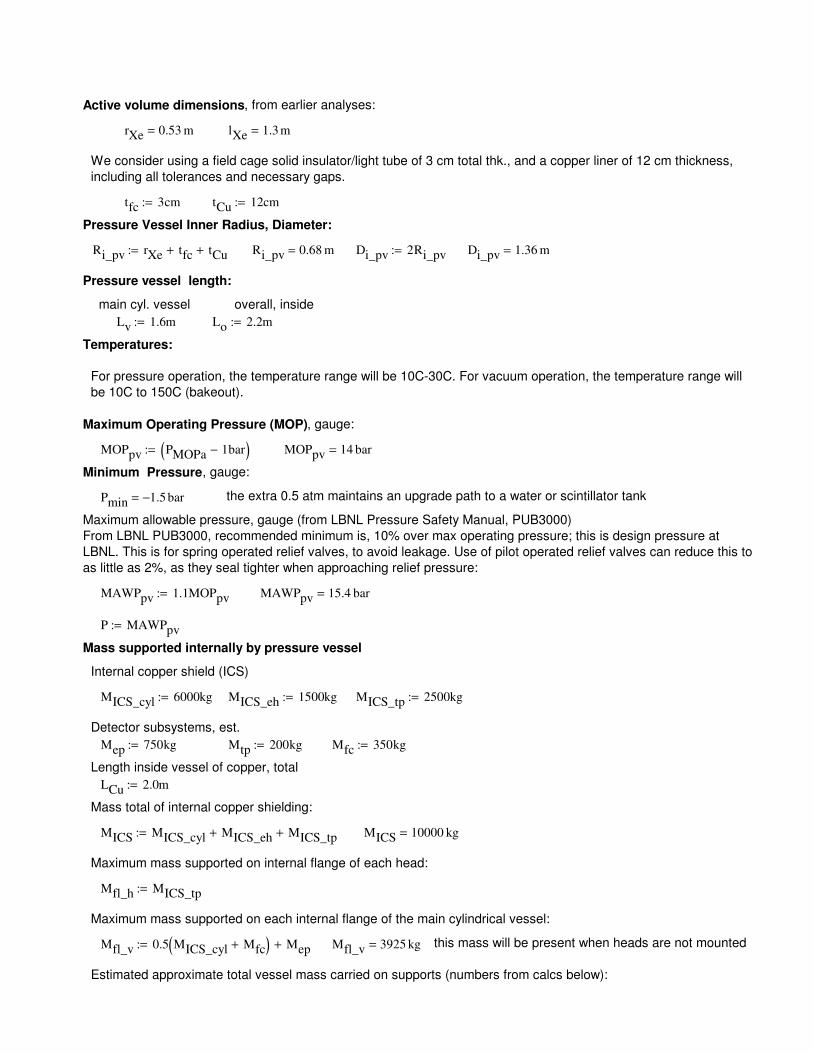
MAWPpv 15.4 bar=
P MAWPpv:=
Mass supported internally by pressure vessel
Internal copper shield (ICS)
MICS_cyl 6000kg:= MICS_eh 1500kg:= MICS_tp 2500kg:=
Detector subsystems, est.
Mep 750kg:= Mtp 200kg:= Mfc 350kg:=
Length inside vessel of copper, total
LCu 2.0m:=
Mass total of internal copper shielding:
MICS MICS_cyl MICS_eh+ MICS_tp+:= MICS 10000 kg=
Maximum mass supported on internal flange of each head:
Mfl_h MICS_tp:=
Maximum mass supported on each internal flange of the main cylindrical vessel:
Mfl_v 0.5 MICS_cyl Mfc+( ) Mep+:= Mfl_v 3925 kg= this mass will be present when heads are not mounted
Estimated approximate total vessel mass carried on supports (numbers from calcs below):
Active volume dimensions, from earlier analyses:
rXe 0.53 m= lXe 1.3 m=
We consider using a field cage solid insulator/light tube of 3 cm total thk., and a copper liner of 12 cm thickness,
including all tolerances and necessary gaps.
tfc 3cm:= tCu 12cm:=
Pressure Vessel Inner Radius, Diameter:
Ri_pv rXe tfc+ tCu+:= Ri_pv 0.68 m= Di_pv 2Ri_pv:= Di_pv 1.36 m=
Pressure vessel length:
main cyl. vessel overall, inside
Lv 1.6m:= Lo 2.2m:=
Temperatures:
For pressure operation, the temperature range will be 10C-30C. For vacuum operation, the temperature range will
be 10C to 150C (bakeout).
Maximum Operating Pressure (MOP), gauge:
MOPpv PMOPa 1bar−( ):= MOPpv 14 bar=
Minimum Pressure, gauge:
Pmin 1.5− bar= the extra 0.5 atm maintains an upgrade path to a water or scintillator tank
Maximum allowable pressure, gauge (from LBNL Pressure Safety Manual, PUB3000)
From LBNL PUB3000, recommended minimum is, 10% over max operating pressure; this is design pressure at
LBNL. This is for spring operated relief valves, to avoid leakage. Use of pilot operated relief valves can reduce this to
as little as 2%, as they seal tighter when approaching relief pressure:
MAWPpv 1.1MOPpv:=
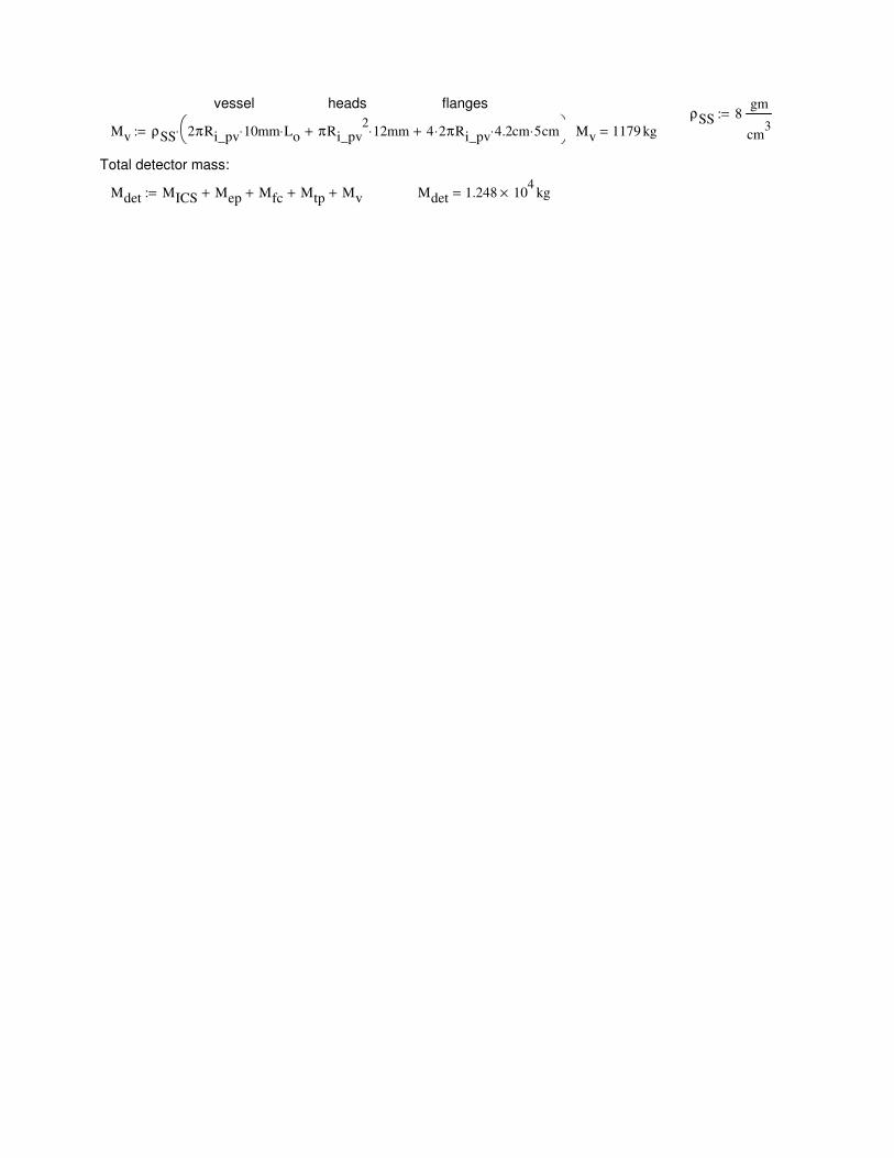
vessel heads flanges ρSS 8
gm
cm3
:=
Mv ρSS 2πRi_pv 10⋅ mm Lo⋅ πRi_pv2
12⋅ mm+ 4 2⋅ πRi_pv 4.2⋅ cm 5⋅ cm+
⋅:= Mv 1179 kg=
Total detector mass:
Mdet MICS Mep+ Mfc+ Mtp+ Mv+:= Mdet 1.248 104
× kg=
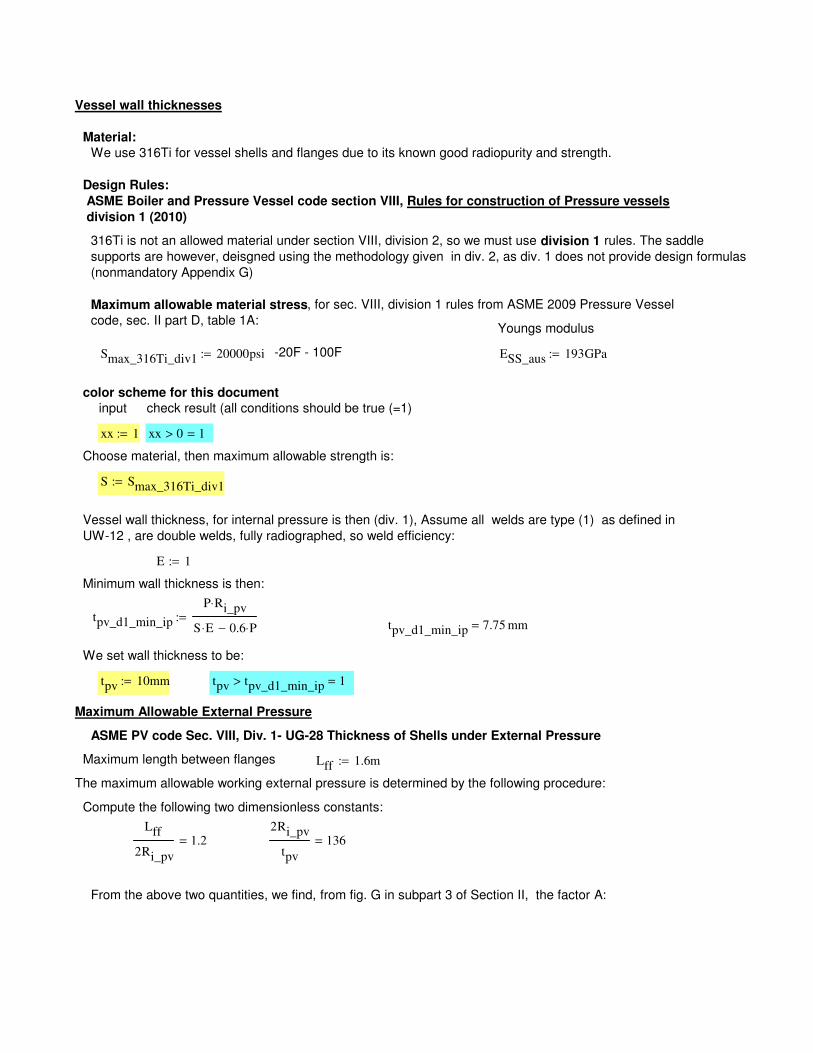
Vessel wall thickness, for internal pressure is then (div. 1), Assume all welds are type (1) as defined in
UW-12 , are double welds, fully radiographed, so weld efficiency:
E 1:=
Minimum wall thickness is then:
tpv_d1_min_ip
P Ri_pv⋅
S E⋅ 0.6 P⋅−:=
tpv_d1_min_ip 7.75 mm=
We set wall thickness to be:
tpv 10mm:= tpv tpv_d1_min_ip> 1=
Maximum Allowable External Pressure
ASME PV code Sec. VIII, Div. 1- UG-28 Thickness of Shells under External Pressure
Maximum length between flanges Lff 1.6m:=
The maximum allowable working external pressure is determined by the following procedure:
Compute the following two dimensionless constants:
Lff
2Ri_pv
1.2=2Ri_pv
tpv
136=
From the above two quantities, we find, from fig. G in subpart 3 of Section II, the factor A:
Vessel wall thicknesses
Material:
We use 316Ti for vessel shells and flanges due to its known good radiopurity and strength.
Design Rules:
ASME Boiler and Pressure Vessel code section VIII, Rules for construction of Pressure vessels
division 1 (2010)
316Ti is not an allowed material under section VIII, division 2, so we must use division 1 rules. The saddle
supports are however, deisgned using the methodology given in div. 2, as div. 1 does not provide design formulas
(nonmandatory Appendix G)
Maximum allowable material stress, for sec. VIII, division 1 rules from ASME 2009 Pressure Vessel
code, sec. II part D, table 1A:Youngs modulus
Smax_316Ti_div1 20000psi:= -20F - 100F ESS_aus 193GPa:=
color scheme for this document
input check result (all conditions should be true (=1)
xx 1:= xx 0> 1=
Choose material, then maximum allowable strength is:
S Smax_316Ti_div1:=
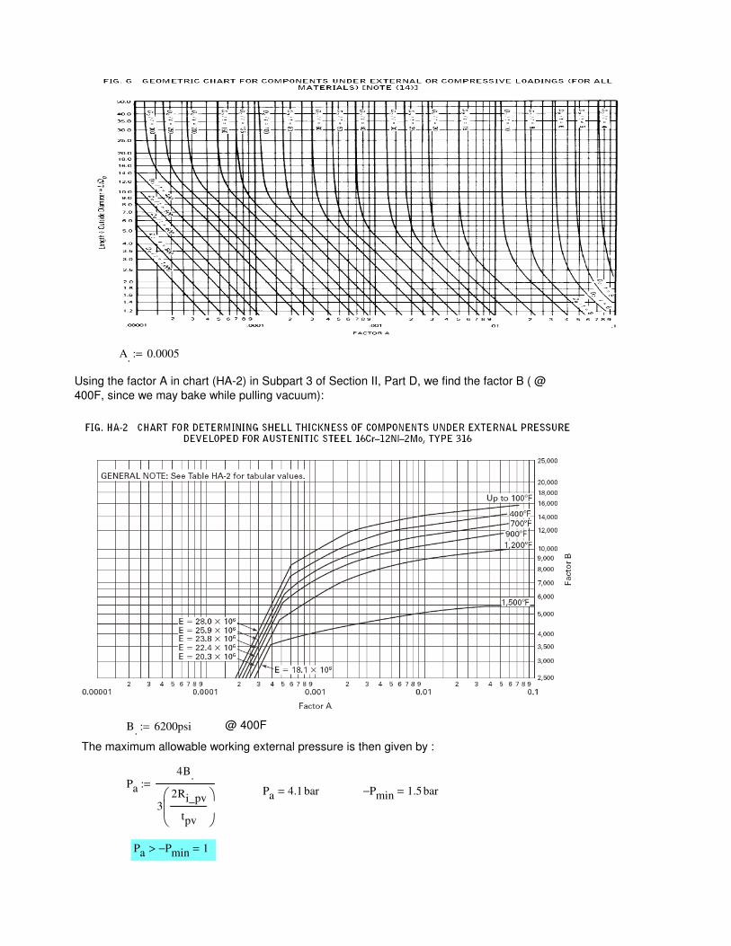
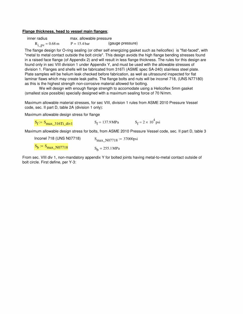
A. 0.0005:=
Using the factor A in chart (HA-2) in Subpart 3 of Section II, Part D, we find the factor B ( @
400F, since we may bake while pulling vacuum):
B. 6200psi:= @ 400F
The maximum allowable working external pressure is then given by :
Pa
4B.
32Ri_pv
tpv
:=Pa 4.1 bar= Pmin− 1.5 bar=
Pa Pmin−> 1=
From sec. VIII div 1, non-mandatory appendix Y for bolted joints having metal-to-metal contact outside of
bolt circle. First define, per Y-3:
Sb 255.1MPa=Sb Smax_N07718:=
Smax_N07718 37000psi:=Inconel 718 (UNS N07718)
Maximum allowable design stress for bolts, from ASME 2010 Pressure Vessel code, sec. II part D, table 3
Sf 2 104
× psi=Sf 137.9 MPa=Sf Smax_316Ti_div1:=
Maximum allowable design stress for flange
Maximum allowable material stresses, for sec VIII, division 1 rules from ASME 2010 Pressure Vessel
code, sec. II part D, table 2A (division 1 only):
The flange design for O-ring sealing (or other self energizing gasket such as helicoflex) is "flat-faced", with
"metal to metal contact outside the bolt circle". This design avoids the high flange bending stresses found
in a raised face flange (of Appendix 2) and will result in less flange thickness. The rules for this design are
found only in sec VIII division 1 under Appendix Y, and must be used with the allowable stresses of
division 1. Flanges and shells will be fabricated from 316Ti (ASME spec SA-240) stainless steel plate.
Plate samples will be helium leak checked before fabrication, as well as ultrasound inspected for flat
laminar flaws which may create leak paths. The flange bolts and nuts will be inconel 718, (UNS N77180)
as this is the highest strength non-corrosive material allowed for bolting.
We will design with enough flange strength to accomodate using a Helicoflex 5mm gasket
(smallest size possible) specially designed with a maximum sealing force of 70 N/mm.
(gauge pressure)P 15.4 bar=Ri_pv 0.68 m=
max. allowable pressureinner radius
Flange thickness, head to vessel main flanges:

68.65 2⋅ 137.3=O-ring mean radius as measured in CAD model:G 1.373m=G 2 Ri_pv .65cm+( ):=
Gasket dia
C 1.43 m⋅:=
Bolt circle (B.C.) dia, C:
B1 1.37 m=B1 B g1+:=
define:
B 1.36 m=B 2Ri_pv:=
Flange ID
A 1.48m:=
Flange OD
r1 5 mm=r1 max .25g1 5mm,( ):=g1 10 mm=g0 10 mm=g1 tpv:=g0 tpv:=
corner radius:hub thickness at flange (no hub)
using nomenclature and formulas from this chart at http://www.tribology-abc.com/calculators/metric-iso.htm
h3 .6134 pt⋅:=pt 1.0mm:=
Choosing ISO fine thread, to maximize root dia.; thread depth is:
nmax 140=nmax truncπC
2.0db
:=maximum number of bolts possible,
using narrow washers:db 16mm:=n 132:=
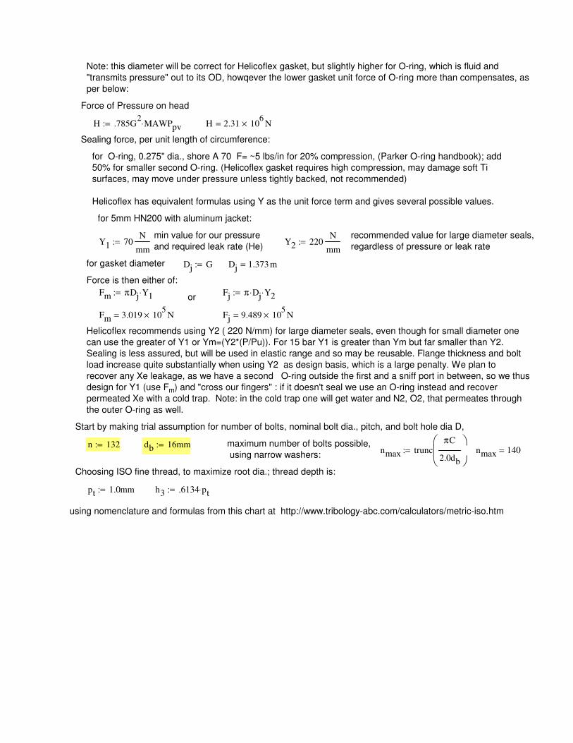
Start by making trial assumption for number of bolts, nominal bolt dia., pitch, and bolt hole dia D,
Helicoflex recommends using Y2 ( 220 N/mm) for large diameter seals, even though for small diameter one
can use the greater of Y1 or Ym=(Y2*(P/Pu)). For 15 bar Y1 is greater than Ym but far smaller than Y2.
Sealing is less assured, but will be used in elastic range and so may be reusable. Flange thickness and bolt
load increase quite substantially when using Y2 as design basis, which is a large penalty. We plan to
recover any Xe leakage, as we have a second O-ring outside the first and a sniff port in between, so we thus
design for Y1 (use Fm) and "cross our fingers" : if it doesn't seal we use an O-ring instead and recover
permeated Xe with a cold trap. Note: in the cold trap one will get water and N2, O2, that permeates through
the outer O-ring as well.
Fj 9.489 105
× N=Fm 3.019 105
× N=
or Fj π Dj⋅ Y2⋅:=Fm πDj Y1⋅:=
Force is then either of:
Dj 1.373 m=Dj G:=for gasket diameter
Y2 220N
mm:=Y1 70
N
mm:=
recommended value for large diameter seals,
regardless of pressure or leak rate
min value for our pressure
and required leak rate (He)
for 5mm HN200 with aluminum jacket:
for O-ring, 0.275" dia., shore A 70 F= ~5 lbs/in for 20% compression, (Parker O-ring handbook); add
50% for smaller second O-ring. (Helicoflex gasket requires high compression, may damage soft Ti
surfaces, may move under pressure unless tightly backed, not recommended)
Helicoflex has equivalent formulas using Y as the unit force term and gives several possible values.
Sealing force, per unit length of circumference:
H 2.31 106
× N=H .785G2
MAWPpv⋅:=
Force of Pressure on head
Note: this diameter will be correct for Helicoflex gasket, but slightly higher for O-ring, which is fluid and
"transmits pressure" out to its OD, howqever the lower gasket unit force of O-ring more than compensates, as
per below:
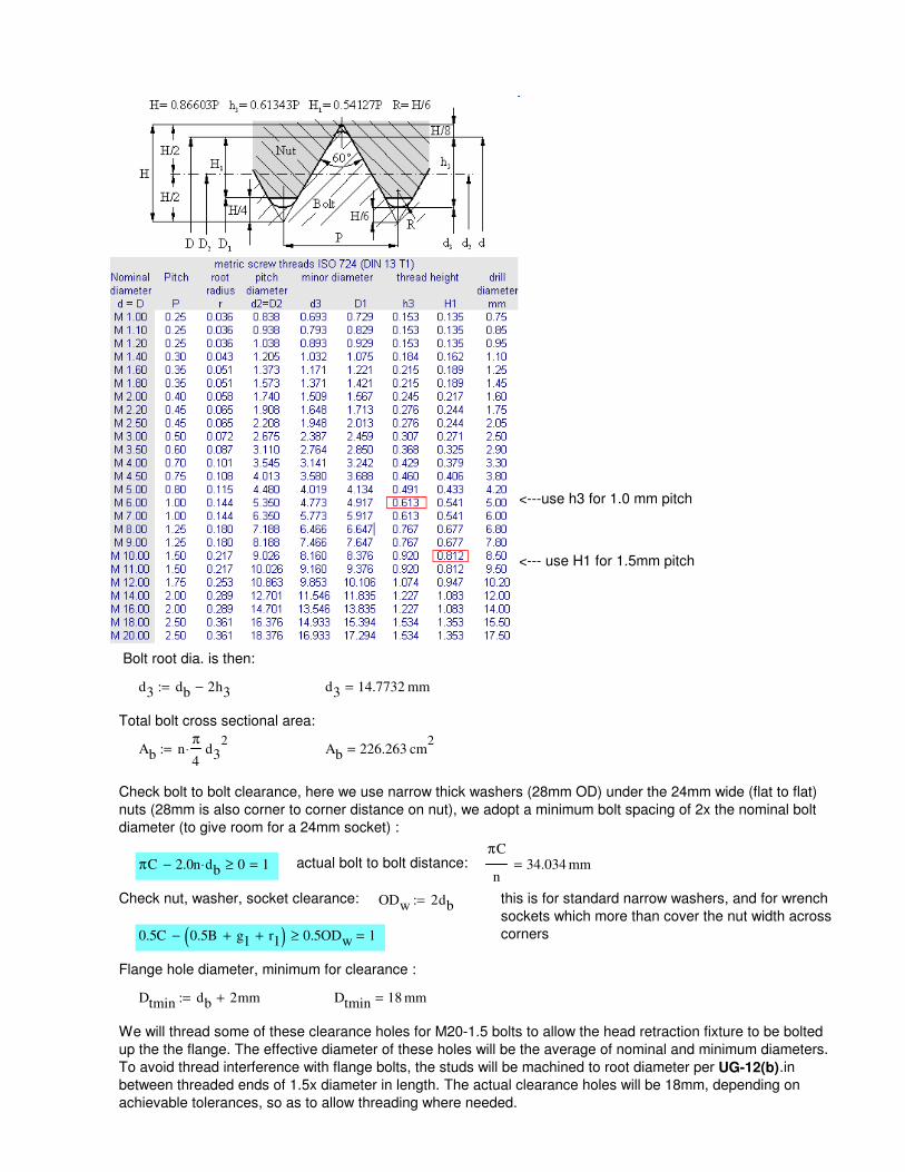
We will thread some of these clearance holes for M20-1.5 bolts to allow the head retraction fixture to be bolted
up the the flange. The effective diameter of these holes will be the average of nominal and minimum diameters.
To avoid thread interference with flange bolts, the studs will be machined to root diameter per UG-12(b).in
between threaded ends of 1.5x diameter in length. The actual clearance holes will be 18mm, depending on
achievable tolerances, so as to allow threading where needed.
Dtmin 18 mm=Dtmin db 2mm+:=
Flange hole diameter, minimum for clearance :
0.5C 0.5B g1+ r1+( )− 0.5ODw≥ 1=
this is for standard narrow washers, and for wrench
sockets which more than cover the nut width across
corners
ODw 2db:=Check nut, washer, socket clearance:
πC
n34.034 mm=actual bolt to bolt distance:πC 2.0n db⋅− 0≥ 1=
Check bolt to bolt clearance, here we use narrow thick washers (28mm OD) under the 24mm wide (flat to flat)
nuts (28mm is also corner to corner distance on nut), we adopt a minimum bolt spacing of 2x the nominal bolt
diameter (to give room for a 24mm socket) :
Ab 226.263 cm2
=Ab nπ
4⋅ d3
2:=
Total bolt cross sectional area:
d3 14.7732 mm=d3 db 2h3−:=
Bolt root dia. is then:
<--- use H1 for 1.5mm pitch
<---use h3 for 1.0 mm pitch
HT 4.353 104
× N=
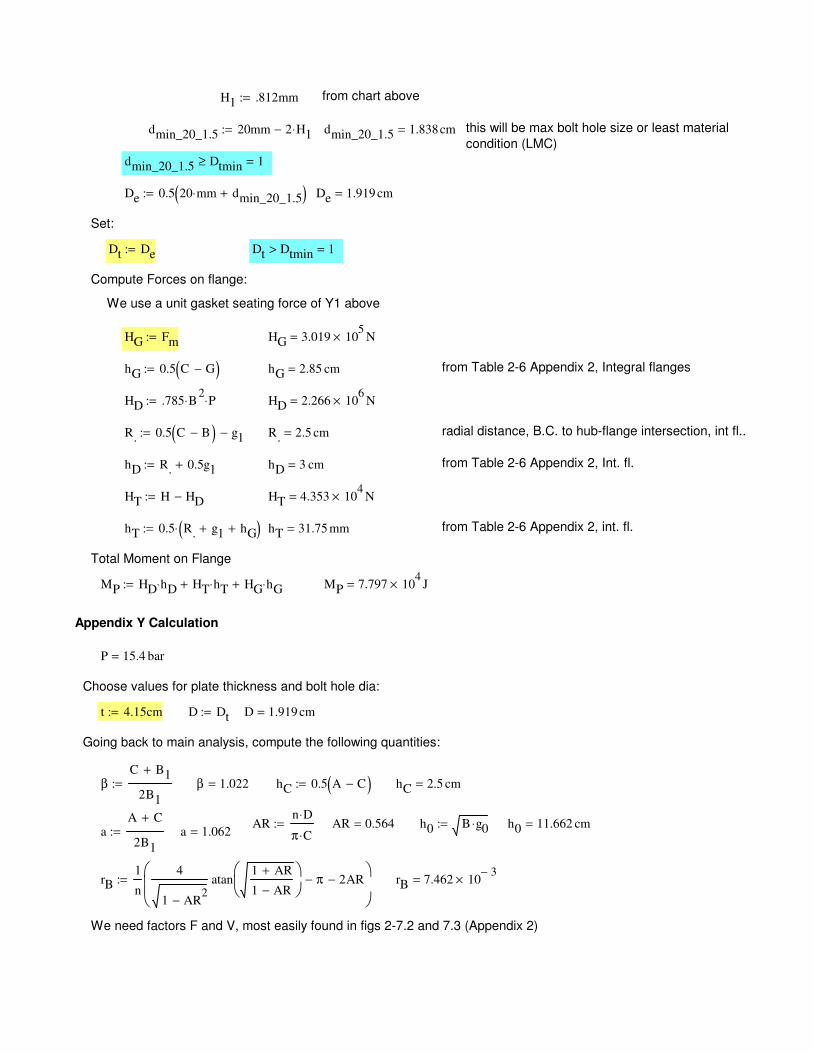
hT 0.5 R. g1+ hG+( )⋅:= hT 31.75 mm= from Table 2-6 Appendix 2, int. fl.
Total Moment on Flange
MP HD hD⋅ HT hT⋅+ HG hG⋅+:= MP 7.797 104
× J=
Appendix Y Calculation
P 15.4 bar=
Choose values for plate thickness and bolt hole dia:
t 4.15cm:= D Dt:= D 1.919 cm=
Going back to main analysis, compute the following quantities:
βC B1+
2B1
:= β 1.022= hC 0.5 A C−( ):= hC 2.5 cm=
ARn D⋅
π C⋅:= AR 0.564= h0 B g0⋅:= h0 11.662 cm=
aA C+
2B1
:= a 1.062=
rB1
n
4
1 AR2
−
atan1 AR+
1 AR−
π− 2AR−
:= rB 7.462 103−
×=
We need factors F and V, most easily found in figs 2-7.2 and 7.3 (Appendix 2)
H1 .812mm:= from chart above
dmin_20_1.5 20mm 2 H1⋅−:= dmin_20_1.5 1.838cm= this will be max bolt hole size or least material
condition (LMC)
dmin_20_1.5 Dtmin≥ 1=
De 0.5 20 mm⋅ dmin_20_1.5+( ):= De 1.919 cm=
Set:
Dt De:= Dt Dtmin> 1=
Compute Forces on flange:
We use a unit gasket seating force of Y1 above
HG Fm:= HG 3.019 105
× N=
hG 0.5 C G−( ):= hG 2.85 cm= from Table 2-6 Appendix 2, Integral flanges
HD .785 B2
⋅ P⋅:= HD 2.266 106
× N=
R. 0.5 C B−( ) g1−:= R. 2.5 cm= radial distance, B.C. to hub-flange intersection, int fl..
hD R. 0.5g1+:= hD 3 cm= from Table 2-6 Appendix 2, Int. fl.
HT H HD−:=
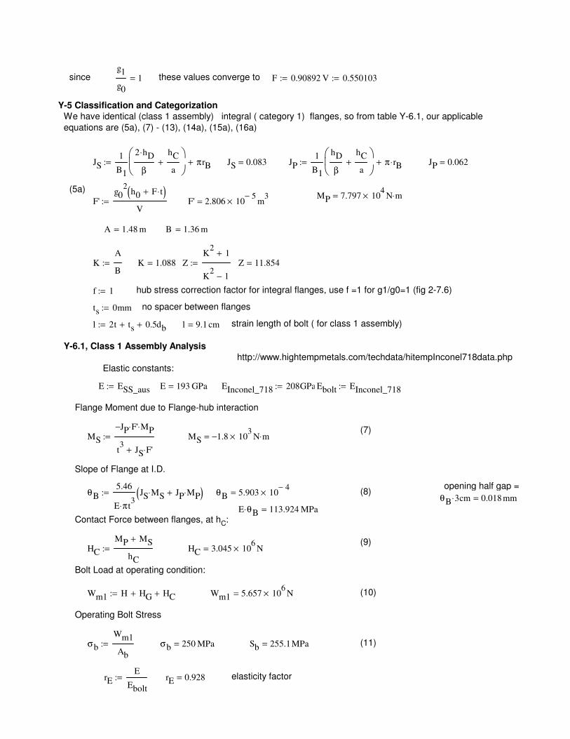
E ESS_aus:= E 193 GPa= EInconel_718 208GPa:= Ebolt EInconel_718:=
Flange Moment due to Flange-hub interaction
(7)MS
JP− F'⋅ MP⋅
t3
JS F'⋅+
:= MS 1.8− 103
× N m⋅=
Slope of Flange at I.D.
opening half gap =θB
5.46
E π⋅ t3
JS MS⋅ JP MP⋅+( ):= θB 5.903 104−
×= (8)θB 3⋅ cm 0.018 mm=
E θB⋅ 113.924 MPa=Contact Force between flanges, at hC:
(9)HC
MP MS+
hC
:= HC 3.045 106
× N=
Bolt Load at operating condition:
Wm1 H HG+ HC+:= Wm1 5.657 106
× N= (10)
Operating Bolt Stress
σb
Wm1
Ab
:= σb 250 MPa= Sb 255.1MPa= (11)
rEE
Ebolt
:= rE 0.928= elasticity factor
since g1
g0
1= these values converge to F 0.90892:= V 0.550103:=
Y-5 Classification and Categorization
We have identical (class 1 assembly) integral ( category 1) flanges, so from table Y-6.1, our applicable
equations are (5a), (7) - (13), (14a), (15a), (16a)
JS1
B1
2 hD⋅
β
hC
a+
πrB+:= JS 0.083= JP1
B1
hD
β
hC
a+
π rB⋅+:= JP 0.062=
(5a)MP 7.797 10
4× N m⋅=
F'g0
2h0 F t⋅+( )
V:= F' 2.806 10
5−× m
3=
A 1.48 m= B 1.36 m=
KA
B:= K 1.088= Z
K2
1+
K2
1−
:= Z 11.854=
f 1:= hub stress correction factor for integral flanges, use f =1 for g1/g0=1 (fig 2-7.6)
ts 0mm:= no spacer between flanges
l 2t ts+ 0.5db+:= l 9.1 cm= strain length of bolt ( for class 1 assembly)
Y-6.1, Class 1 Assembly Analysis
http://www.hightempmetals.com/techdata/hitempInconel718data.php
Elastic constants:
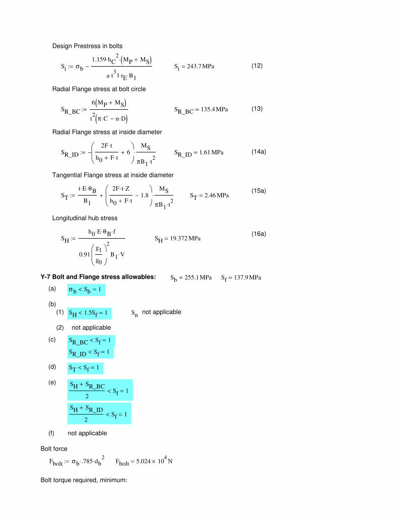
σb Sb< 1=
(b)
(1) SH 1.5Sf< 1= Snnot applicable
(2) not applicable
(c) SR_BC Sf< 1=
SR_ID Sf< 1=
(d) ST Sf< 1=
(e) SH SR_BC+
2Sf< 1=
SH SR_ID+
2Sf< 1=
(f) not applicable
Bolt force
Fbolt σb .785⋅ db2
⋅:= Fbolt 5.024 104
× N=
Bolt torque required, minimum:
Design Prestress in bolts
Si σb
1.159 hC2
⋅ MP MS+( )⋅
a t3
⋅ l rE⋅ B1⋅
−:= Si 243.7 MPa= (12)
Radial Flange stress at bolt circle
SR_BC
6 MP MS+( )
t2
π C⋅ n D⋅−( ):= SR_BC 135.4 MPa= (13)
Radial Flange stress at inside diameter
SR_ID
2F t⋅
h0 F t⋅+6+
−MS
πB1 t2
⋅
⋅:= SR_ID 1.61 MPa= (14a)
Tangential Flange stress at inside diameter
(15a)ST
t E⋅ θB⋅
B1
2F t⋅ Z⋅
h0 F t⋅+1.8−
MS
πB1 t2
⋅
⋅+:= ST 2.46 MPa=
Longitudinal hub stress
(16a)SH
h0 E⋅ θB⋅ f⋅
0.91g1
g0
2
B1 V⋅
:= SH 19.372 MPa=
Y-7 Bolt and Flange stress allowables: Sb 255.1MPa= Sf 137.9 MPa=
(a)
Additional Calculations for Shielding Weight:
Shear stress in inner flange lip from shield (could happen only if flange bolts come loose, are left loose, or if joint
opens under pressure, otherwise friction of faces will support shield, given additional tension, as permissible under
non-mandatory Appendix S above )
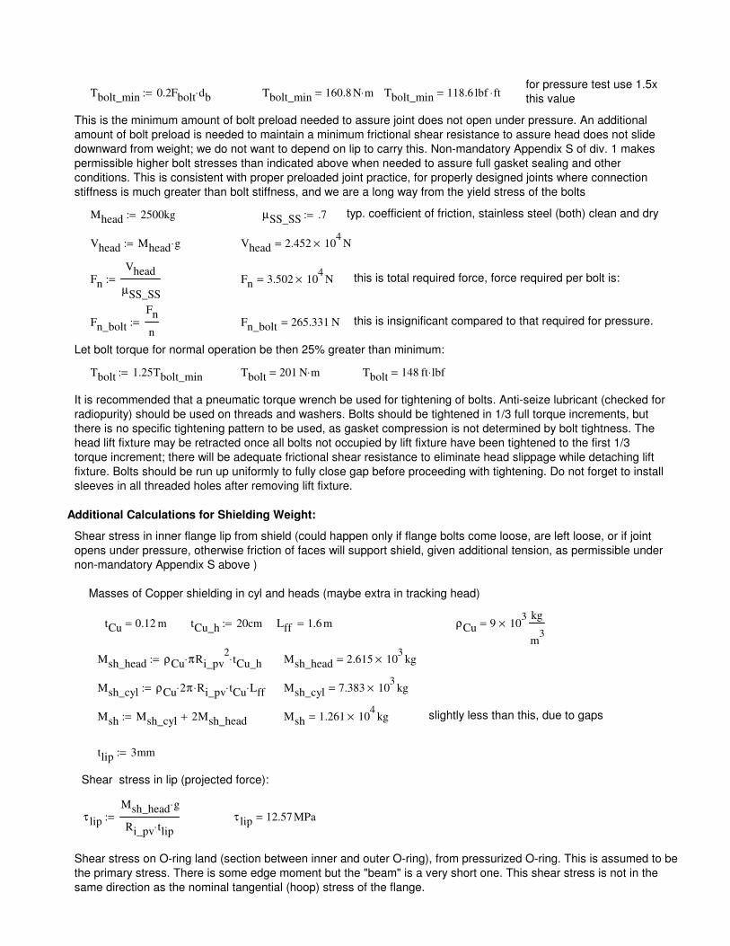
Masses of Copper shielding in cyl and heads (maybe extra in tracking head)
tCu 0.12 m= tCu_h 20cm:= Lff 1.6 m= ρCu 9 103
×kg
m3
=
Msh_head ρCu π⋅ Ri_pv2
tCu_h⋅:= Msh_head 2.615 103
× kg=
Msh_cyl ρCu 2⋅ π Ri_pv⋅ tCu⋅ Lff⋅:= Msh_cyl 7.383 103
× kg=
Msh Msh_cyl 2Msh_head+:= Msh 1.261 104
× kg= slightly less than this, due to gaps
tlip 3mm:=
Shear stress in lip (projected force):
τ lip
Msh_head g⋅
Ri_pv tlip⋅:= τ lip 12.57 MPa=
Shear stress on O-ring land (section between inner and outer O-ring), from pressurized O-ring. This is assumed to be
the primary stress. There is some edge moment but the "beam" is a very short one. This shear stress is not in the
same direction as the nominal tangential (hoop) stress of the flange.
for pressure test use 1.5x
this valueTbolt_min 0.2Fbolt db⋅:= Tbolt_min 160.8 N m⋅= Tbolt_min 118.6 lbf ft⋅=
This is the minimum amount of bolt preload needed to assure joint does not open under pressure. An additional
amount of bolt preload is needed to maintain a minimum frictional shear resistance to assure head does not slide
downward from weight; we do not want to depend on lip to carry this. Non-mandatory Appendix S of div. 1 makes
permissible higher bolt stresses than indicated above when needed to assure full gasket sealing and other
conditions. This is consistent with proper preloaded joint practice, for properly designed joints where connection
stiffness is much greater than bolt stiffness, and we are a long way from the yield stress of the bolts
Mhead 2500kg:= µSS_SS .7:= typ. coefficient of friction, stainless steel (both) clean and dry
Vhead Mhead g⋅:= Vhead 2.452 104
× N=
Fn
Vhead
µSS_SS
:= Fn 3.502 104
× N= this is total required force, force required per bolt is:
Fn_bolt
Fn
n:= Fn_bolt 265.331 N= this is insignificant compared to that required for pressure.
Let bolt torque for normal operation be then 25% greater than minimum:
Tbolt 1.25Tbolt_min:= Tbolt 201 N m⋅= Tbolt 148 ft lbf⋅=
It is recommended that a pneumatic torque wrench be used for tightening of bolts. Anti-seize lubricant (checked for
radiopurity) should be used on threads and washers. Bolts should be tightened in 1/3 full torque increments, but
there is no specific tightening pattern to be used, as gasket compression is not determined by bolt tightness. The
head lift fixture may be retracted once all bolts not occupied by lift fixture have been tightened to the first 1/3
torque increment; there will be adequate frictional shear resistance to eliminate head slippage while detaching lift
fixture. Bolts should be run up uniformly to fully close gap before proceeding with tightening. Do not forget to install
sleeves in all threaded holes after removing lift fixture.
Ssy_65500_H2 131 MPa=Ssy_65500_H2 0.5Sy_65500_H2:=
Sy_65500_H2 262.001 MPa=Sy_65500_H2 38000psi:=
This stress is inconsequential, as bolts will be ASME SB-98 silicon copper UNS C65500 - HO2 (half hard cond);
this material should be radiopure and has > 20% elongation in the hard condition. Shear strength in yield is 50%
Sy.
τbolt_cubar 12.347 MPa=τbolt_cubar
0.5Mcubar_vfan g⋅
5π
4⋅ droot_M6
2:=
Mcubar_vfan 225kg:=
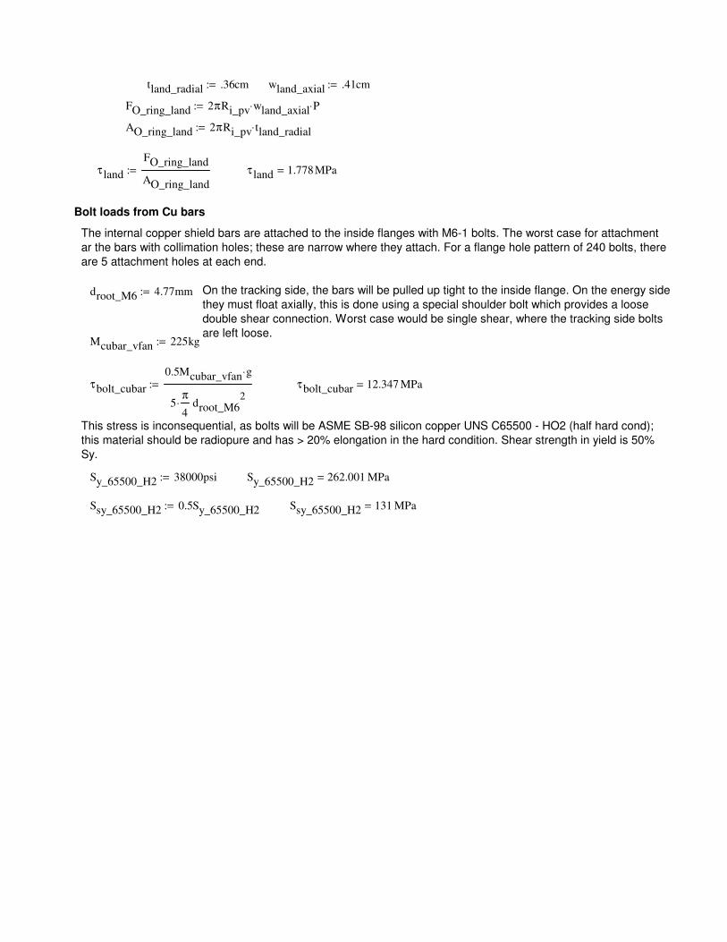
On the tracking side, the bars will be pulled up tight to the inside flange. On the energy side
they must float axially, this is done using a special shoulder bolt which provides a loose
double shear connection. Worst case would be single shear, where the tracking side bolts
are left loose.
droot_M6 4.77mm:=
The internal copper shield bars are attached to the inside flanges with M6-1 bolts. The worst case for attachment
ar the bars with collimation holes; these are narrow where they attach. For a flange hole pattern of 240 bolts, there
are 5 attachment holes at each end.
Bolt loads from Cu bars
τ land 1.778MPa=τ land
FO_ring_land
AO_ring_land
:=
AO_ring_land 2πRi_pv tland_radial⋅:=
FO_ring_land 2πRi_pv wland_axial⋅ P⋅:=
wland_axial .41cm:=tland_radial .36cm:=
Strain, O-ring cross section, in axial direction
εOpa 0.5− εOpt:= εOpa 0.016−=
O-ring dia., stretched:
dOps dOp 1 εOpa+( )⋅:= dOps
4.918
5.253
mm=
Resulting squeeze (using the vectorize operator to continue parallel calculations)
sqp
dOps dOpg−
dOps
→
:= sqp
22.74
27.659
%= 15% sqp< 30%<1
1
=
O-ring groove cross sectional area,
AOpg dOpg ROgpo ROgpi−( )⋅1
2
π
2−
rip2
⋅−
→
:= AOpg 2.558 105−
× m2
=
Trelleborg recommends no more than 85% fill ratio
Rfp
π
4dOps
2
AOpg
→
:= Rfp
74.274
84.718
%= Rfp 85%<1
1
=
Outer (vacuum) O-ring:
Groove wall radii (average), depth, inner corner radii:
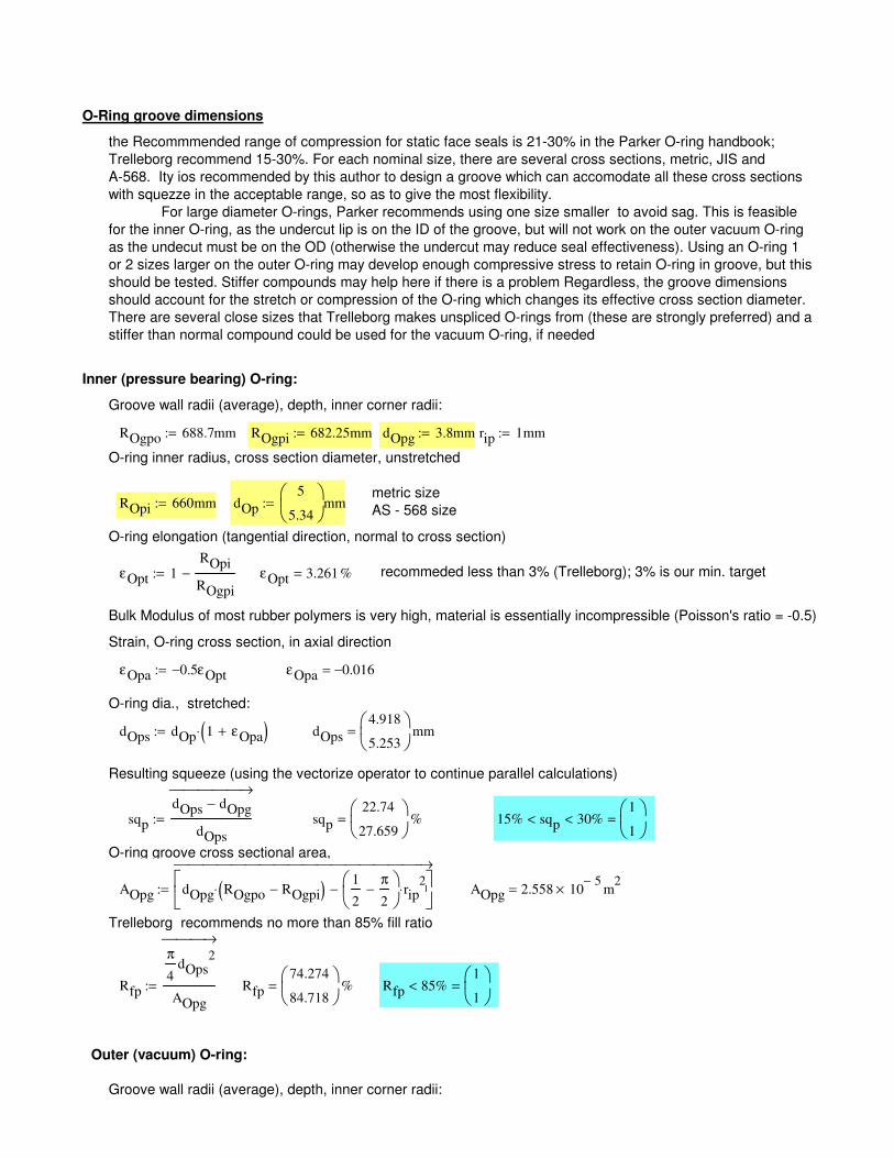
O-Ring groove dimensions
the Recommmended range of compression for static face seals is 21-30% in the Parker O-ring handbook;
Trelleborg recommend 15-30%. For each nominal size, there are several cross sections, metric, JIS and
A-568. Ity ios recommended by this author to design a groove which can accomodate all these cross sections
with squezze in the acceptable range, so as to give the most flexibility.
For large diameter O-rings, Parker recommends using one size smaller to avoid sag. This is feasible
for the inner O-ring, as the undercut lip is on the ID of the groove, but will not work on the outer vacuum O-ring
as the undecut must be on the OD (otherwise the undercut may reduce seal effectiveness). Using an O-ring 1
or 2 sizes larger on the outer O-ring may develop enough compressive stress to retain O-ring in groove, but this
should be tested. Stiffer compounds may help here if there is a problem Regardless, the groove dimensions
should account for the stretch or compression of the O-ring which changes its effective cross section diameter.
There are several close sizes that Trelleborg makes unspliced O-rings from (these are strongly preferred) and a
stiffer than normal compound could be used for the vacuum O-ring, if needed
Inner (pressure bearing) O-ring:
Groove wall radii (average), depth, inner corner radii:
ROgpo 688.7mm:= ROgpi 682.25mm:= dOpg 3.8mm:= rip 1mm:=
O-ring inner radius, cross section diameter, unstretched
metric sizeROpi 660mm:= dOp
5
5.34
mm:=AS - 568 size
O-ring elongation (tangential direction, normal to cross section)
εOpt 1ROpi
ROgpi
−:= εOpt 3.261 %= recommeded less than 3% (Trelleborg); 3% is our min. target
Bulk Modulus of most rubber polymers is very high, material is essentially incompressible (Poisson's ratio = -0.5)
εOva 0.027=
O-ring dia., stretched:
dOvs dOv 1 εOva+( )⋅:= dOvs
3.08
3.645
mm=
Resulting squeeze
sqv
dOvs dOvg−
dOvs
→
:= sqv
15.591
28.669
%= 15% sqv< 30%<1
1
=
O-ring groove cross sectional area,
AOvg dOvg ROgvo ROgvi−( )⋅1
2
π
2−
riv2
⋅−
→
:= AOvg 1.268 105−
× m2
=
Fill ratio; Trelleborg recommends no more than 85%:
We should have a comfortable margin hereRfv
π
4dOvs
2
AOvg
→
:= Rfv
58.752
82.269
%= Rfv 85%<1
1
=
ROgvo 697.66mm:= ROgvi 692.93mm:= dOvg 2.6mm:= riv 0.6mm:=
O-ring inner radius, cross section diameter, unstretched
metric size note: there are several intermediate sizes ROvi 730mm:= dOv
3
3.55
mm:=metric/JIS size
O-ring elongation (tangential direction, normal to cross section)
εOvt 1ROvi
ROgvi
−:= εOvt 5.35− %= recommended less than 3% (Trelleborg); we go for ~5% here as
compression should not compromise integrity
Bulk Modulus of most rubber polymers is very high, material is essentially incompressible (Poisson's ratio = -0.5)
Strain, O-ring cross section, in axial direction
εOva 0.5− εOvt:=
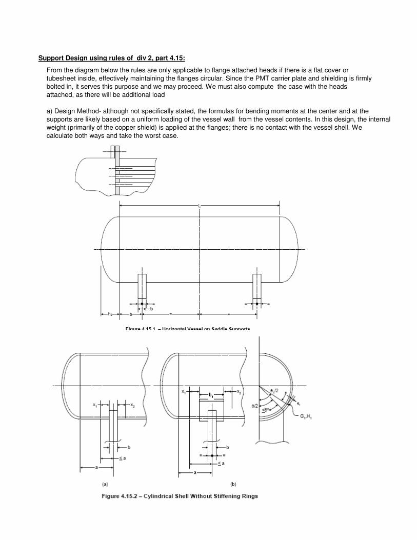
Support Design using rules of div 2, part 4.15:
From the diagram below the rules are only applicable to flange attached heads if there is a flat cover or
tubesheet inside, effectively maintaining the flanges circular. Since the PMT carrier plate and shielding is firmly
bolted in, it serves this purpose and we may proceed. We must also compute the case with the heads
attached, as there will be additional load
a) Design Method- although not specifically stated, the formulas for bending moments at the center and at the
supports are likely based on a uniform loading of the vessel wall from the vessel contents. In this design, the internal
weight (primarily of the copper shield) is applied at the flanges; there is no contact with the vessel shell. We
calculate both ways and take the worst case.
M1' 1.706 104
× N m⋅=
M2' M1':= M2' 1.706 104
× N m⋅=
TQ L 2a−( )⋅
L4h2
3+
:= T 3.215 104
× N=
4.15.3.3 - longitudinal stresses
distributed load (ASME assumption) end load ( actual)
σ1
P Rm⋅
2tpv
M2
π Rm2tpv
−:= σ1 52.789 MPa= σ1'
P Rm⋅
2tpv
M2'
π Rm2tpv
−:= σ1' 52.301 MPa=
σ2'
P Rm⋅
2tpv
M2'
π Rm2tpv
+:= σ2' 54.616 MPa=σ2
P Rm⋅
2tpv
M2
π Rm2tpv
+:= σ2 54.128 MPa=
same stress at supports, since these are stiffened, as a<0.5Rm and close to a torispheric head a 0.5Rm< 1=
σ3
P Rm⋅
2tpv
M1
π Rm2tpv
−:=σ3 53.345 MPa= σ3'
P Rm⋅
2tpv
M1'
π Rm2tpv
−:= σ3' 52.301 MPa=
L Lff:= Mtot 12000kg:= L 1.6 m=
b 1.5cm:= amin .18Lff:= amin 28.8 cm= a 29cm:= θ 120deg:= Rm Ri_pv 0.5tpv+:=
b1 min b 1.56 Rm tpv⋅⋅+( ) 2 a⋅, := b1 14.411 cm= k 0.1:=h2 20cm:=
θ1 θθ
12+:= θ1 130 deg= maximum reaction load at each support:
Q 0.5Mtot g⋅:= Q 5.884 104
× N=
M1 Q− a⋅ 1
1a
L−
Rm2
h22
−
2 a⋅ L⋅+
14h2
3L+
−
⋅:= M1 1.676 103
× N m⋅= Q a⋅ 1.706 104
× J=
M2
Q L⋅
4
12 Rm
2h2
2−
⋅
L2
+
14 h2⋅
3L+
4a
L−
⋅:= M2 9.875 103
× N m⋅=
M1' Q a⋅:=
K5 0.76=K51 cos α( )+
π α− sin α( ) cos α( )⋅+:=
4.15.3.5 Circumferential Stress
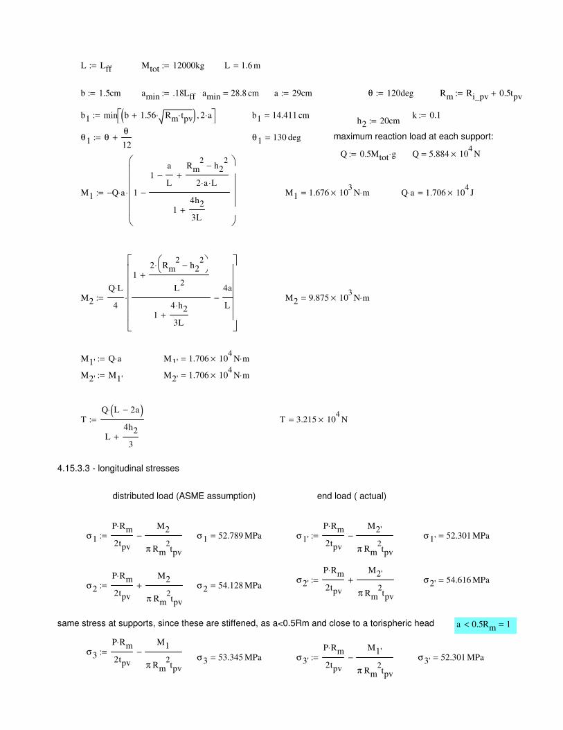
(4.15.14)τ1 1.749MPa=τ1
K2 T⋅
πRm tpv⋅:=c)
here we use c), formula for cyl. shell with no stiffening rings and which is not stiffened by a formed head, flat
cover or tubesheet. This is worst case, as we havea flange, which can be considered as one half of a
stiffening ring pair for each support.
K2 1.171=K2sin α( )
π α− sin α( ) cos α( )+:=
α 1.99=α 0.95 πθ
2−
:=
∆ 1.396=∆π
6
5θ
12+:=
4.15.3.4 - Shear stresses
σ4' 54.616 MPa=σ4'
P Rm⋅
2tpv
M1'
π Rm2tpv
+:=σ4 53.572 MPa=σ4
P Rm⋅
2tpv
M1
π Rm2tpv
+:=
b1 14.411 cm=
σ7Q−
4tpv b x1+ x2+( )⋅
12K7 Q⋅ Rm⋅
L tpv2
⋅
−:= σ7 156.484 MPa= (4.15.25)
too high; we need a reinforcement plate of thickness;
tr tpv:= strength ratio: η 1:= (4.15.29)
σ7rQ−
4 tpv η tr⋅+( ) b1⋅
12K7 Q⋅ Rm⋅
L tpv η tr⋅+( )2
⋅
−:= σ7r 36.569 MPa= (4.15.28)
3)f) Acceptance Criteria
S 1.379 108
× Pa= S 2 104
× psi=
σ7r 1.25S< 1=
4) this section not applicable as tr 2tpv> 0=
β πθ
2−:= β 2.094=
K6
3 cos β( )⋅
4
sin β( )β
2
⋅5 sin β( )⋅ cos β( )⋅
4 β⋅−
cos β( )3
2+
sin β( )4 β⋅
−cos β( )
4+ β sin β( )⋅
sin β( )β
2
1
2−
sin 2 β⋅( )4 β⋅
−
⋅−
2 π⋅sin β( )
β
2
1
2−
sin 2 β⋅( )4 β⋅
−
⋅
:=
K6 0.221−=
a
Rm
0.5< 1=
K7
K6
4:= K7 0.055−=
a) Max circ bending moment
1) Cyl shell without a stiffening ring
Mβ K7 Q⋅ Rm⋅:= Mβ 2.223− 103
× N m⋅=
c) Circ. stress in shell, without stiffening rings
x1 0.78 Rm tpv⋅:= x1 6.456 cm= x2 x1:= k 0.1=
σ6
K5− Q⋅ k⋅
tpv b x1+ x2+( )⋅:= σ6 3.104− MPa=
L 8Rm< 1=L 1.6 m=
4.15.3.6 - Saddle support, horizontal force given below must be resisted by low point of saddle ( where height = hs)
Fh Q1 cos β( )+ 0.5 sin β( )
2⋅−
π β− β sin β( )⋅ cos β( )+
⋅:= Fh 5.242 104
× N= hs 9cm:=
σh
Fh
b hs⋅:= σh 38.833 MPa=
Support on, and Attachment to floor
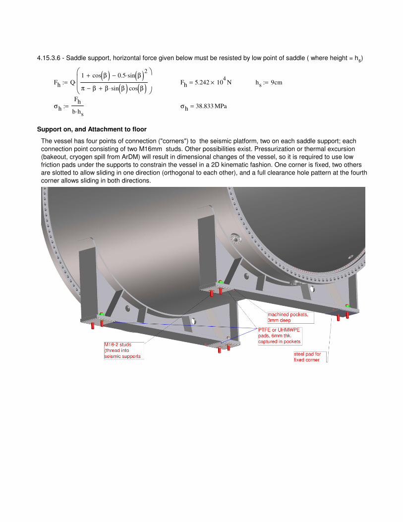
The vessel has four points of connection ("corners") to the seismic platform, two on each saddle support; each
connection point consisting of two M16mm studs. Other possibilities exist. Pressurization or thermal excursion
(bakeout, cryogen spill from ArDM) will result in dimensional changes of the vessel, so it is required to use low
friction pads under the supports to constrain the vessel in a 2D kinematic fashion. One corner is fixed, two others
are slotted to allow sliding in one direction (orthogonal to each other), and a full clearance hole pattern at the fourth
corner allows sliding in both directions.
σhoop 106.137 MPa=σhoop
P Ri_pv⋅
tpv
:=σ long 53.041 MPa=σ long
HD
2πRi_pv tpv⋅:=
stresses in vessel shell, longitudinal and tangential (hoop):
ws 1.2m:=
saddle support width, transverse
HD 2.266 106
× N=tpv 10 mm=Ri_pv 0.68 m=Ls 1.02 m=Ls Lff 2a−:=
length between saddle supports:Pressure load, longitudinal
Vessel length and width change under pressurization and heating:
These deflections (from either pressure or thermal excursion) are substantial enough to warrant the use of low
friction pads under three of the four supports, which will allow the vessel to slide both lengthwise and widthwise
when pressurizing/depressurizing or baking. In addition there is a remote possibility of cryogen spillage, perhaps
from ArDM which may chill the vessel, so a capacity for contraction equal to the above expansion should be
designed in. Bolt holes should be slotted, with sliding keys to give uniform bearing pressure on slots under
transverse loads, as described above. In addition, each corner should have one large tapped hole for a
leveling/jacking screw that will allow bearing pad replacement, in situ.
Bolt shear stress from seismic acceleration
The maximum horizontal acceleration from a seismic event is expected to be much less than 1 m/s2; we use a
design value here of:
ahoriz 2m
s2
:=
Fhoriz Mtot ahoriz⋅:= Fhoriz 2.4 104
× N=
Bolt area required:
We calculate for all horizontal load taken on two corners only, since we will have sliding supports. We calculate for
austenitic stainless steel bolts:
Ssup_bolt Sf:= Ssup_bolt 137.895 MPa=
maximum shear stress:
Ss_sup_bolt 0.5Ssup_bolt:=
bolt area required, per corner
Asup_bolts
0.5Fhoriz
Ss_sup_bolt
:= Asup_bolts 1.74 cm2
=
assume 2 bolts per corner, for redundancy and symmetry about support web. with 2 bolts, the only critical
dimension to match between the holes in the support and the holes in the seismic frame are the distance
between the hole pairs (hole pattern rotation need not be matched). The sliding keys can be custom machined if
needed to compensate for mismatch.
length width changes from pressure:ESS_aus 193 GPa=
δLs
σ long Ls⋅
ESS_aus
:= δLs 0.28 mm=
δws
σhoop ws⋅
ESS_aus
:= δws 0.66 mm= in reality, the support itself will restrain a significant portion of this
deflection, since the saddle is welded to the vessel shell
thermal growth, 150C bakeout
αSS 16 106−
⋅ K1−
:= up to 100C
∆Tv 150K 20K−:=
ε th_SS αSS ∆Tv⋅:=
δv_t ε th_SS ws⋅:= δv_t 2.496 mm=
δv_l ε th_SS Ls⋅:= δv_l 2.122 mm=
bakeout will only be performed under vacuum condition.
Saddle support bending stress
Use an M24-2 bolt at each corner. Lubricate or PTFE coat (preferred)
djs_root 20.061 mm=djs_root4
πAjs:=
Ajs 3.161cm2
=Ajs
Fjs
0.9 Sy_316Ti⋅:=
Sy_316Ti 30000psi:=
Use 90% yield strength as allowable stress (non critical)
Fjs 1.323 104
× lbf=Fjs 5.884 104
× N=Fjs 0.5Mtot g⋅:=
Each jacking screw must be able to lift half the entire weight of the detector. We look for a low grade bolt that can
support this force
Jacking screw diameter
We choose only unfilled plastics, as most fillers are not radiopure (possible exception: bronze filled PTFE). PTFE
(unfilled), @500 psi , has little margin for stability, but any creep flow will act to equalize pressure over all 4
supports, resulting in a lower, stable pressure. Furthermore it is the only material that can withstand 150C,
although the temperature at the supports will be substantially less than 150C, due to the poor thermal
conductivity of SS. Cooling of supports should be performed in case of bakeout, regardless. Bronze-filled PTFE,
UHMWPE (non-oil-filled), nylon, or acetal may also be used; cooling of support pads during bakeout would be
mandatory.
Material for Bearing Pad
frrom Slideways bearing catalogue (similar to table 10-4 in J. Shigley, Mech. Engin. 3rd ed.)
Maximum allowable bearing pressures and temperatures (we may bake vessel at 150C with copper shielding inside)
Pbearing 425.162 psi=Pbearing 0.5Mtot g⋅
Abearing
:=
Bearing pressure is then (assuming a non-leveled condition where full weight is supported on two diagonal corners):
Abearing 200.724 cm2
=Abearing b12
4Asup_bolts−:=
Assume a full square contact patch under each corner;accounting for bolts and keys:
Bearing design
Support uses (2) M16-2.0 bolts on each corner, root diameter is 12mm
this is required minimum root diameterdsup_bolt 10.526 mm=dsup_bolt4
π0.5⋅ Asup_bolts:=
Iw
tw hw3
⋅
12:= Ifll
wfll tfll3
⋅
12:=
Iw 64 cm4
= Ifll 9.608 cm4
=Ir 1.201 cm
4=
dr 0.5tr c1−:= dw tr 0.5 hw⋅+( ) c1−:= dfll tr hw+ 0.5 tfll⋅+( ) c1−:=
dr 5.935− cm= dw 1.435− cm= dfll 3.565 cm=
Is_min Ir Ar dr2
⋅+
Iw Aw dw
2⋅+
+ Ifll Afll dfll
2⋅+
+:=
Is_min 973.459 cm4
=
Consider as a uniformly loaded beam, simply supported on each end
load per unit width (along the long dimension; transverse to vessel axis)
Mtot 1.2 104
× kg=ω
0.55Mtot g⋅
ws
:= ω 539.366N
cm=
Moment at center:
Msup_max
ω ws2
⋅
8:= Msup_max 9.709 10
3× N m⋅=
Maximum stress, tensile in flange under vessel
σsup_max
Msup_max 0.5⋅ hw
Is_min
:= σsup_max 39.893 MPa=
This is low enough to allow support only at corners; we do not need to support under the full width of the support
feet.
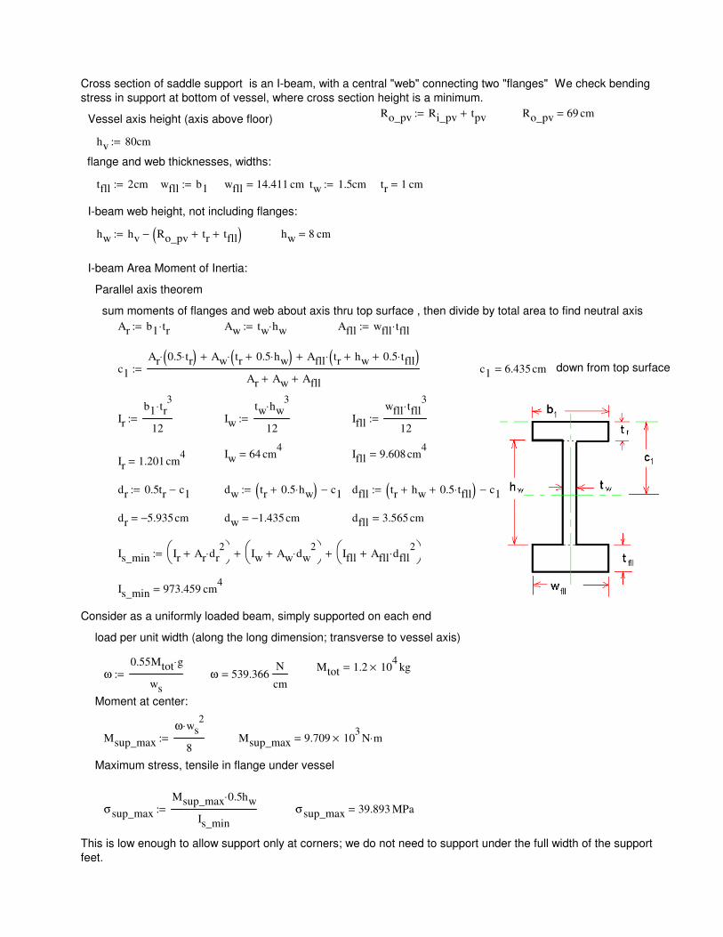
Cross section of saddle support is an I-beam, with a central "web" connecting two "flanges" We check bending
stress in support at bottom of vessel, where cross section height is a minimum.
Ro_pv Ri_pv tpv+:= Ro_pv 69 cm=Vessel axis height (axis above floor)
hv 80cm:=
flange and web thicknesses, widths:
tfll 2cm:= wfll b1:= wfll 14.411 cm= tw 1.5cm:= tr 1 cm=
I-beam web height, not including flanges:
hw hv Ro_pv tr+ tfll+( )−:= hw 8 cm=
I-beam Area Moment of Inertia:
Parallel axis theorem
sum moments of flanges and web about axis thru top surface , then divide by total area to find neutral axis
Ar b1 tr⋅:= Aw tw hw⋅:= Afll wfll tfll⋅:=
c1
Ar 0.5 tr⋅( )⋅ Aw tr 0.5 hw⋅+( )⋅+ Afll tr hw+ 0.5 tfll⋅+( )⋅+
Ar Aw+ Afll+:= c1 6.435 cm= down from top surface
Ir
b1 tr3
⋅
12:=
Sdiv1 1.379 108
× Pa=
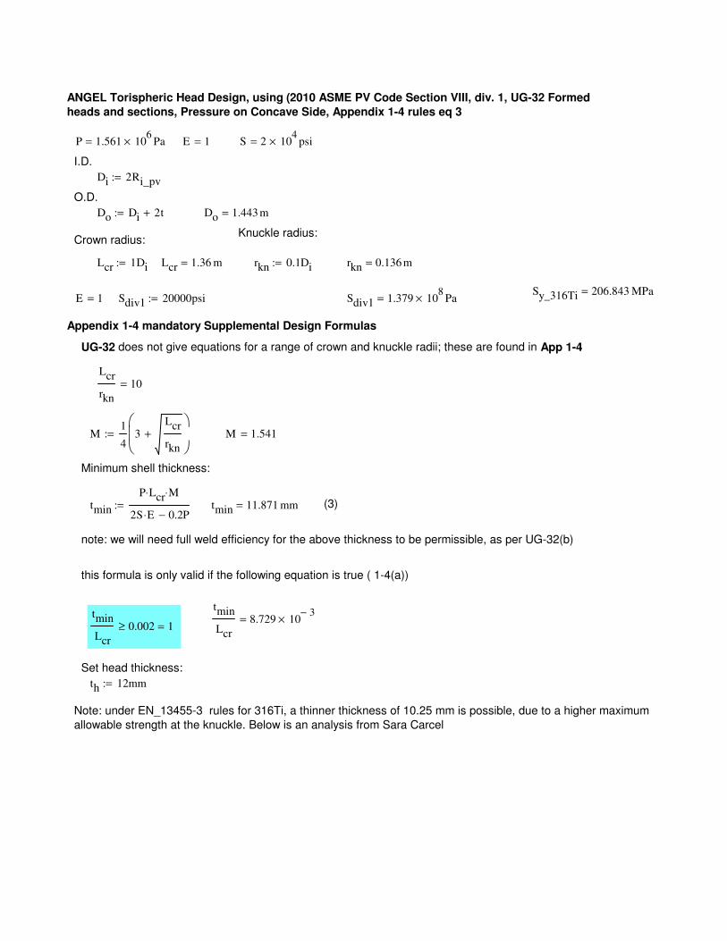
Appendix 1-4 mandatory Supplemental Design Formulas
UG-32 does not give equations for a range of crown and knuckle radii; these are found in App 1-4
Lcr
rkn
10=
M1
43
Lcr
rkn
+
:= M 1.541=
Minimum shell thickness:
tmin
P Lcr⋅ M⋅
2S E⋅ 0.2P−:= tmin 11.871 mm= (3)
note: we will need full weld efficiency for the above thickness to be permissible, as per UG-32(b)
this formula is only valid if the following equation is true ( 1-4(a))
tmin
Lcr
8.729 103−
×=tmin
Lcr
0.002≥ 1=
Set head thickness:
th 12mm:=
Note: under EN_13455-3 rules for 316Ti, a thinner thickness of 10.25 mm is possible, due to a higher maximum
allowable strength at the knuckle. Below is an analysis from Sara Carcel
ANGEL Torispheric Head Design, using (2010 ASME PV Code Section VIII, div. 1, UG-32 Formed
heads and sections, Pressure on Concave Side, Appendix 1-4 rules eq 3
P 1.561 106
× Pa= E 1= S 2 104
× psi=
I.D.
Di 2Ri_pv:=
O.D.
Do Di 2t+:= Do 1.443 m=
Knuckle radius: Crown radius:
Lcr 1Di:= Lcr 1.36 m= rkn 0.1Di:= rkn 0.136 m=
Sy_316Ti 206.843 MPa=E 1= Sdiv1 20000psi:=
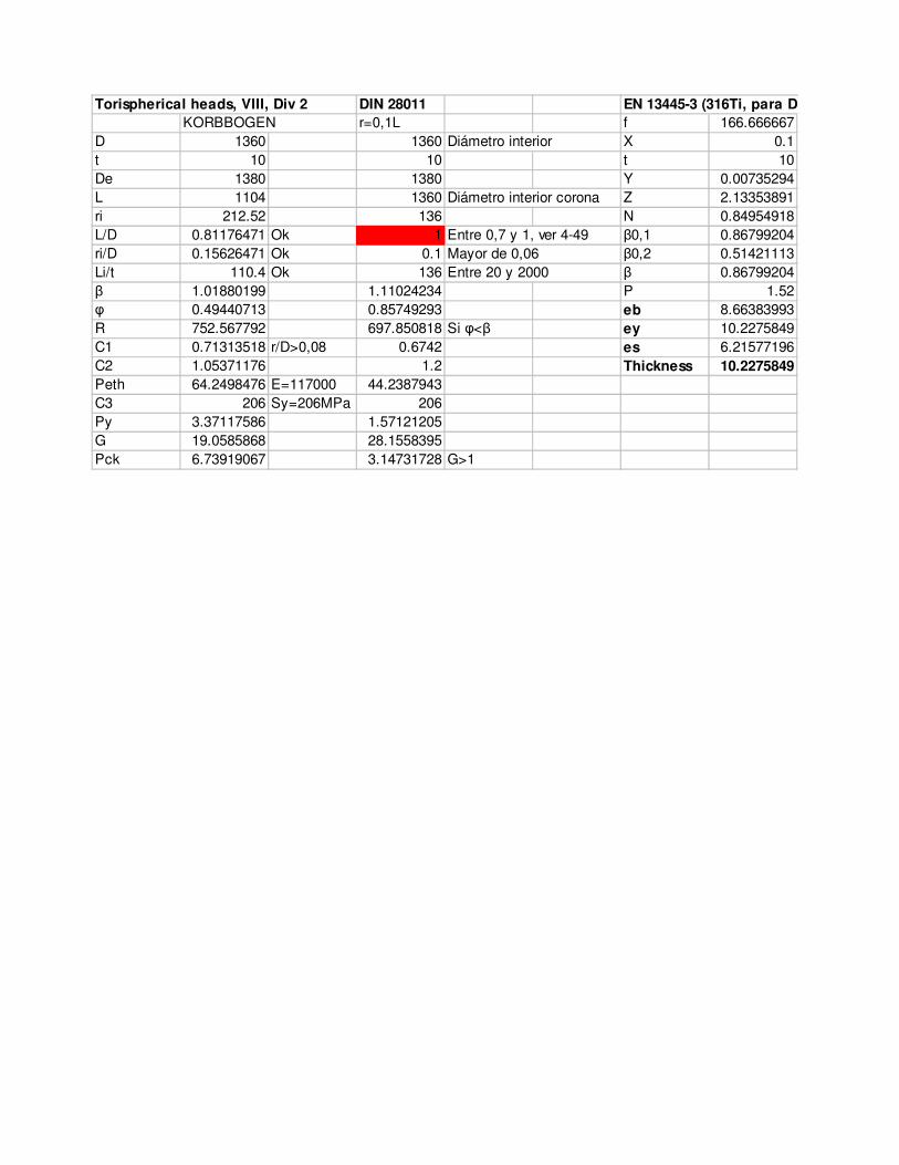
Torispherical heads, VIII, Div 2 DIN 28011 EN 13445-3 (316Ti, para DIN 28011
KORBBOGEN r=0,1L f 166.666667
D 1360 1360 Diámetro interior X 0.1
t 10 10 t 10
De 1380 1380 Y 0.00735294
L 1104 1360 Diámetro interior corona Z 2.13353891
ri 212.52 136 N 0.84954918
L/D 0.81176471 Ok 1 Entre 0,7 y 1, ver 4-49 β0,1 0.86799204
ri/D 0.15626471 Ok 0.1 Mayor de 0,06 β0,2 0.51421113
Li/t 110.4 Ok 136 Entre 20 y 2000 β 0.86799204
β 1.01880199 1.11024234 P 1.52
φ 0.49440713 0.85749293 eb 8.66383993
R 752.567792 697.850818 Si φ<β ey 10.2275849
C1 0.71313518 r/D>0,08 0.6742 es 6.21577196
C2 1.05371176 1.2 Thickness 10.2275849
Peth 64.2498476 E=117000 44.2387943
C3 206 Sy=206MPa 206
Py 3.37117586 1.57121205
G 19.0585868 28.1558395
Pck 6.73919067 3.14731728 G>1
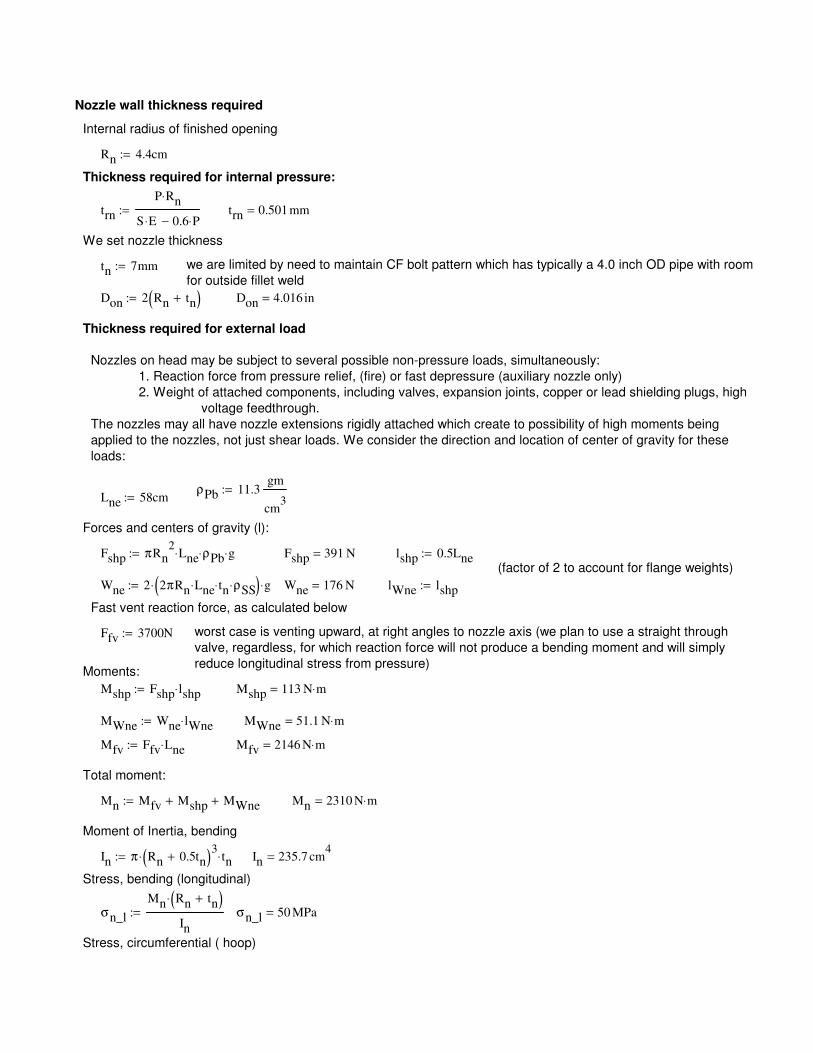
lWne lshp:=
Fast vent reaction force, as calculated below
Ffv 3700N:= worst case is venting upward, at right angles to nozzle axis (we plan to use a straight through
valve, regardless, for which reaction force will not produce a bending moment and will simply
reduce longitudinal stress from pressure)Moments:
Mshp Fshp lshp⋅:= Mshp 113 N m⋅=
MWne Wne lWne⋅:= MWne 51.1 N m⋅=
Mfv Ffv Lne⋅:= Mfv 2146 N m⋅=
Total moment:
Mn Mfv Mshp+ MWne+:= Mn 2310 N m⋅=
Moment of Inertia, bending
In π Rn 0.5tn+( )3
⋅ tn⋅:= In 235.7 cm4
=
Stress, bending (longitudinal)
σn_l
Mn Rn tn+( )⋅
In
:= σn_l 50 MPa=
Stress, circumferential ( hoop)
Nozzle wall thickness required
Internal radius of finished opening
Rn 4.4cm:=
Thickness required for internal pressure:
trn
P Rn⋅
S E⋅ 0.6 P⋅−:= trn 0.501 mm=
We set nozzle thickness
tn 7mm:= we are limited by need to maintain CF bolt pattern which has typically a 4.0 inch OD pipe with room
for outside fillet weld
Don 2 Rn tn+( ):= Don 4.016 in=
Thickness required for external load
Nozzles on head may be subject to several possible non-pressure loads, simultaneously:
1. Reaction force from pressure relief, (fire) or fast depressure (auxiliary nozzle only)
2. Weight of attached components, including valves, expansion joints, copper or lead shielding plugs, high
voltage feedthrough.
The nozzles may all have nozzle extensions rigidly attached which create to possibility of high moments being
applied to the nozzles, not just shear loads. We consider the direction and location of center of gravity for these
loads:
ρPb 11.3gm
cm3
:=Lne 58cm:=
Forces and centers of gravity (l):
Fshp πRn2
Lne⋅ ρPb⋅ g⋅:= Fshp 391 N= lshp 0.5Lne:=(factor of 2 to account for flange weights)
Wne 2 2πRn Lne⋅ tn⋅ ρSS⋅( )⋅ g⋅:= Wne 176 N=
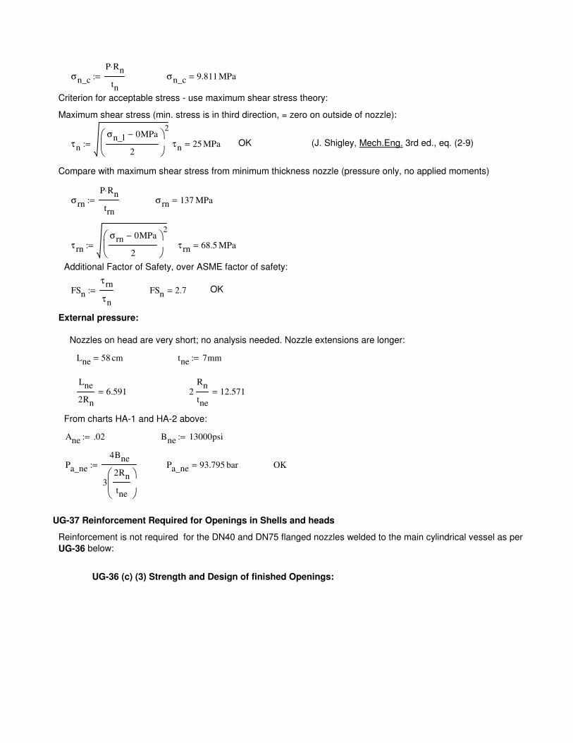
UG-36 (c) (3) Strength and Design of finished Openings:
Reinforcement is not required for the DN40 and DN75 flanged nozzles welded to the main cylindrical vessel as per
UG-36 below:
UG-37 Reinforcement Required for Openings in Shells and heads
OKPa_ne 93.795 bar=Pa_ne
4Bne
32Rn
tne
:=
Bne 13000psi:=Ane .02:=
From charts HA-1 and HA-2 above:
2Rn
tne
12.571=Lne
2Rn
6.591=
tne 7mm:=Lne 58 cm=
Nozzles on head are very short; no analysis needed. Nozzle extensions are longer:
External pressure:
σn_c
P Rn⋅
tn
:= σn_c 9.811 MPa=
Criterion for acceptable stress - use maximum shear stress theory:
Maximum shear stress (min. stress is in third direction, = zero on outside of nozzle):
τn
σn_l 0MPa−
2
2
:= τn 25 MPa= OK (J. Shigley, Mech.Eng. 3rd ed., eq. (2-9)
Compare with maximum shear stress from minimum thickness nozzle (pressure only, no applied moments)
σrn
P Rn⋅
trn
:= σrn 137 MPa=
τ rn
σrn 0MPa−
2
2
:= τ rn 68.5 MPa=
Additional Factor of Safety, over ASME factor of safety:
FSn
τ rn
τn
:= FSn 2.7= OK
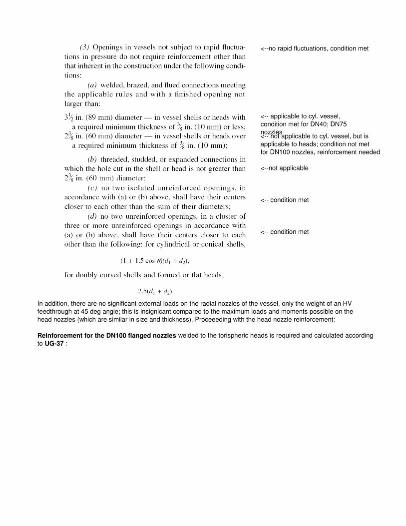
<--no rapid fluctuations, condition met
<-- applicable to cyl. vessel,
condition met for DN40; DN75
nozzles<-- not applicable to cyl. vessel, but is
applicable to heads; condition not met
for DN100 nozzles, reinforcement needed
<--not applicable
<-- condition met
<-- condition met
In addition, there are no significant external loads on the radial nozzles of the vessel, only the weight of an HV
feedthrough at 45 deg angle; this is insignicant compared to the maximum loads and moments possible on the
head nozzles (which are similar in size and thickness). Proceeeding with the head nozzle reinforcement:
Reinforcement for the DN100 flanged nozzles welded to the torispheric heads is required and calculated according
to UG-37 :
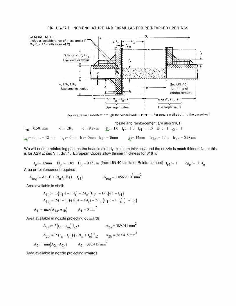
Dp 0.158 m= (from UG-40 Limits of Reinforcement) fr4 1:= lege .71 te⋅:=
Area or reinforcement required:
Areq d tr⋅ F⋅ 2tn tr⋅ F⋅ 1 fr1−( )⋅+:= Areq 1.056 103
× mm2
=
Area available in shell:
A1a d E1 t⋅ F tr⋅−( )⋅ 2 tn⋅ E1 t⋅ F tr⋅−( )⋅ 1 fr1−( )⋅−:=
A1b 2 t tn+( )⋅ E1 t⋅ F tr⋅−( )⋅ 2 tn⋅ E1 t⋅ F tr⋅−( )⋅ 1 fr1−( )⋅−:=
A1 max A1a A1b,( ):= A1 0 mm2
=
Area available in nozzle projecting outwards
A2a 5 tn trn−( ) fr2⋅ t⋅:= A2a 389.914 mm2
=
A2b 2 tn trn−( )⋅ 2.5tn te+( )⋅ fr2⋅:= A2b 383.415 mm2
=
A2 min A2a A2b,( ):= A2 383.415 mm2
=
Area available in nozzle projecting inwards
nozzle and reinforcement are also 316Ti
trn 0.501 mm= d 2Rn:= d 8.8 cm= F 1.0:= fr 1.0:= fr1 1.0:= E1 1:= fr2 1:=
tr th:= tr 12 mm= ti 0mm:= h 0mm:= legi 0mm:= t 12mm:= legn 1.4tn:= legn 0.98 cm=
We will need a reinforcing pad, as the head is already minimum thickness and the nozzle is much thinner. Note: this
is for ASME; sec VIII, div. 1. European Codes allow thinner thickness for 316Ti.
te 12mm:= Dp 1.8d:=
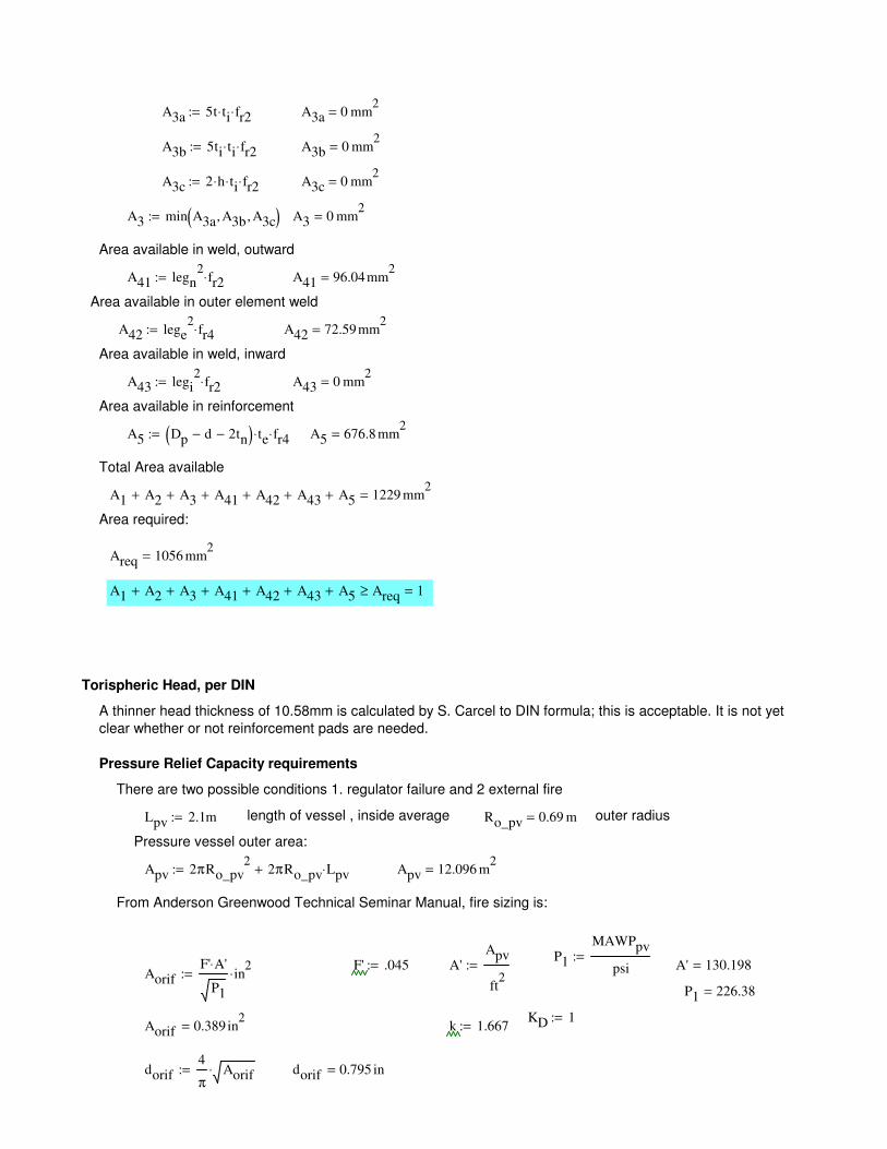
A1 A2+ A3+ A41+ A42+ A43+ A5+ Areq≥ 1=
Torispheric Head, per DIN
A thinner head thickness of 10.58mm is calculated by S. Carcel to DIN formula; this is acceptable. It is not yet
clear whether or not reinforcement pads are needed.
Pressure Relief Capacity requirements
There are two possible conditions 1. regulator failure and 2 external fire
Lpv 2.1m:= length of vessel , inside average Ro_pv 0.69 m= outer radius
Pressure vessel outer area:
Apv 2πRo_pv2
2πRo_pv Lpv⋅+:= Apv 12.096 m2
=
From Anderson Greenwood Technical Seminar Manual, fire sizing is:
P1
MAWPpv
psi:=
F' .045:= A'Apv
ft2
:= A' 130.198=Aorif
F' A'⋅
P1
in2
⋅:=
P1 226.38=
KD 1:=Aorif 0.389 in
2= k 1.667:=
dorif4
πAorif⋅:= dorif 0.795 in=
A3a 5t ti⋅ fr2⋅:= A3a 0 mm2
=
A3b 5ti ti⋅ fr2⋅:= A3b 0 mm2
=
A3c 2 h⋅ ti⋅ fr2⋅:= A3c 0 mm2
=
A3 min A3a A3b, A3c,( ):= A3 0 mm2
=
Area available in weld, outward
A41 legn2
fr2⋅:= A41 96.04mm2
=
Area available in outer element weld
A42 lege2
fr4⋅:= A42 72.59mm2
=
Area available in weld, inward
A43 legi2
fr2⋅:= A43 0 mm2
=
Area available in reinforcement
A5 Dp d− 2tn−( ) te⋅ fr4⋅:= A5 676.8 mm2
=
Total Area available
A1 A2+ A3+ A41+ A42+ A43+ A5+ 1229 mm2
=
Area required:
Areq 1056 mm2
=
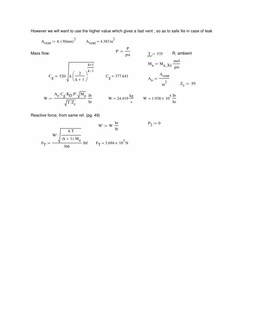
FT 3.694 103
× N=FT
W'k T⋅
k 1+( ) Ma⋅⋅
366lbf⋅:=
W' Whr
lb⋅:=
P2 0:=
Reactive force, from same ref. (pg. 49)
W 1.938 105
×lb
hr=W 24.419
kg
s=W
Ao Cg⋅ KD⋅ P'⋅ Ma⋅
T Zc⋅
lb
hr⋅:=
Zc .95:=
Ao
Avent
in2
:=Cg 377.641=Cg 520 k
2
k 1+
k 1+
k 1−
⋅⋅:=
Ma Ma_Xemol
gm⋅:=
R, ambientT 535:=Mass flow:P'
P
psi:=
Avent 4.383 in2
=Avent π 30mm( )2
⋅:=
However we will want to use the higher value which gives a fast vent , so as to safe Xe in case of leak
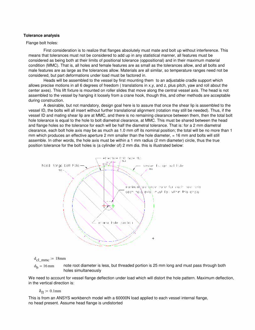
Tolerance analysis
Flange bolt holes:
First consideration is to realize that flanges absolutely must mate and bolt up without interference. This
means that tolerances must not be considered to add up in any statistical manner, all features must be
considered as being both at their limits of positional tolerance (oppositional) and in their maximum material
condition (MMC). That is, all holes and female features are as small as the tolerances allow, and all bolts and
male features are as large as the tolerances allow. Materials are all similar, so temperature ranges need not be
considered, but part deformations under load must be factored in.
Heads will be assembled to the vessel by first mounting them to an adjustable cradle support which
allows precise motions in all 6 degrees of freedom ( translations in x,y, and z, plus pitch, yaw and roll about the
center axes). This lift fixture is mounted on roller slides that move along the central vessel axis. The head is not
assembled to the vessel by hanging it loosely from a crane hook, though this, and other methods are acceptable
during construction.
A desirable, but not mandatory, design goal here is to assure that once the shear lip is assembled to the
vessel ID, the bolts will all insert without further translational alignment (rotation may still be needed). Thus, if the
vessel ID and mating shear lip are at MMC, and there is no remaining clearance between them, then the total bolt
hole tolerance is equal to the hole to bolt diametral clearance, at MMC. This must be shared between the head
and flange holes so the tolerance for each will be half the diametral tolerance. That is: for a 2 mm diametral
clearance, each bolt hole axis may be as much as 1.0 mm off its nominal position; the total will be no more than 1
mm which produces an effective aperture 2 mm smaller than the hole diameter, = 16 mm and bolts will still
assemble. In other words, the hole axis must be within a 1 mm radius (2 mm diameter) circle, thus the true
position tolerance for the bolt holes is (a cylinder of) 2 mm dia. this is illustrated below:
dcl_mmc 18mm:=
db 16 mm= note root diameter is less, but threaded portion is 25 mm long and must pass through both
holes simultaneously
We need to account for vessel flange deflection under load which will distort the hole pattern. Maximum deflection,
in the vertical direction is:
δfl 0.1mm:=
This is from an ANSYS workbench model with a 60000N load applied to each vessel internal flange,
no head present. Assume head flange is undistorted
( )
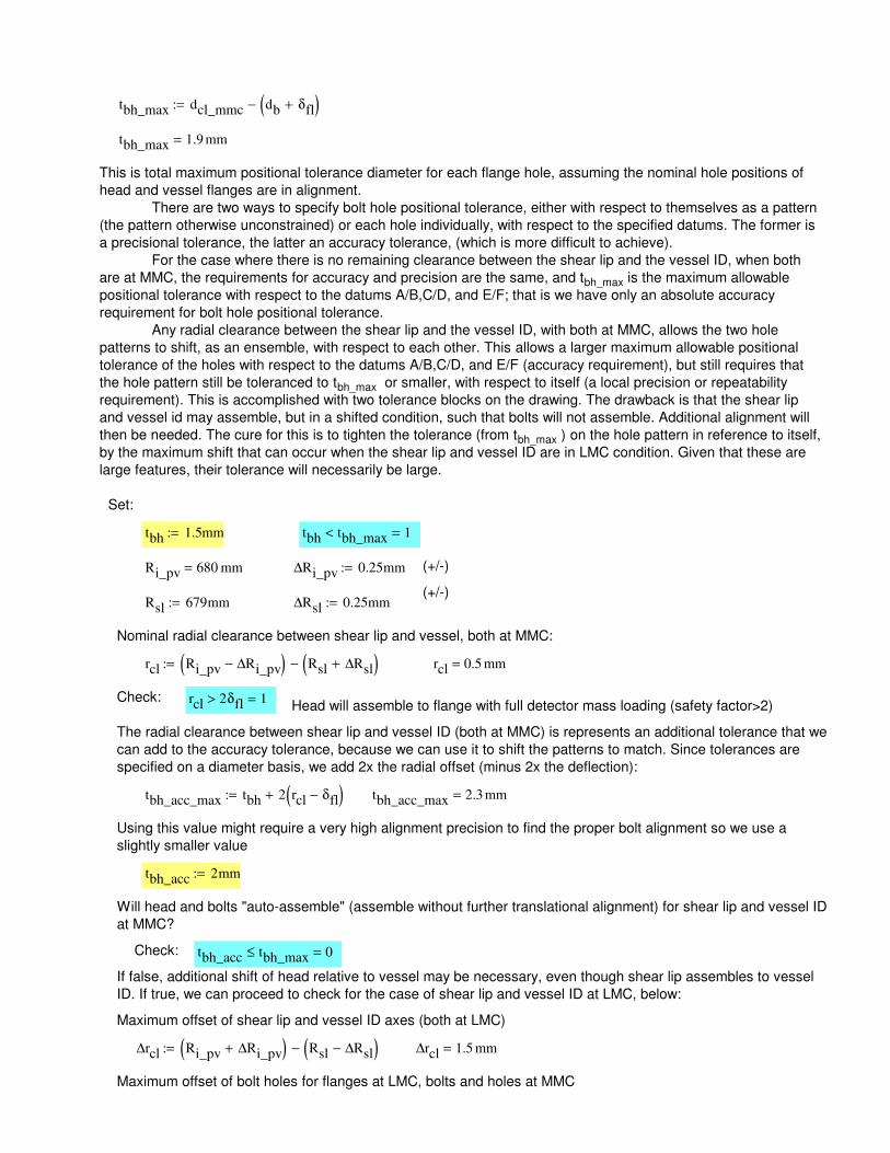
Maximum offset of bolt holes for flanges at LMC, bolts and holes at MMC
∆rcl 1.5 mm=∆rcl Ri_pv ∆Ri_pv+( ) Rsl ∆Rsl−( )−:=
Maximum offset of shear lip and vessel ID axes (both at LMC)
If false, additional shift of head relative to vessel may be necessary, even though shear lip assembles to vessel
ID. If true, we can proceed to check for the case of shear lip and vessel ID at LMC, below:
tbh_acc tbh_max≤ 0=Check:
Will head and bolts "auto-assemble" (assemble without further translational alignment) for shear lip and vessel ID
at MMC?
tbh_acc 2mm:=
Using this value might require a very high alignment precision to find the proper bolt alignment so we use a
slightly smaller value
tbh_acc_max 2.3 mm=tbh_acc_max tbh 2 rcl δfl−( )+:=
The radial clearance between shear lip and vessel ID (both at MMC) is represents an additional tolerance that we
can add to the accuracy tolerance, because we can use it to shift the patterns to match. Since tolerances are
specified on a diameter basis, we add 2x the radial offset (minus 2x the deflection):
Head will assemble to flange with full detector mass loading (safety factor>2)rcl 2δfl> 1=Check:
rcl 0.5 mm=rcl Ri_pv ∆Ri_pv−( ) Rsl ∆Rsl+( )−:=
Nominal radial clearance between shear lip and vessel, both at MMC:
∆Rsl 0.25mm:=Rsl 679mm:=(+/-)
(+/-)∆Ri_pv 0.25mm:=Ri_pv 680 mm=
tbh tbh_max< 1=tbh 1.5mm:=
Set:
This is total maximum positional tolerance diameter for each flange hole, assuming the nominal hole positions of
head and vessel flanges are in alignment.
There are two ways to specify bolt hole positional tolerance, either with respect to themselves as a pattern
(the pattern otherwise unconstrained) or each hole individually, with respect to the specified datums. The former is
a precisional tolerance, the latter an accuracy tolerance, (which is more difficult to achieve).
For the case where there is no remaining clearance between the shear lip and the vessel ID, when both
are at MMC, the requirements for accuracy and precision are the same, and tbh_max is the maximum allowable
positional tolerance with respect to the datums A/B,C/D, and E/F; that is we have only an absolute accuracy
requirement for bolt hole positional tolerance.
Any radial clearance between the shear lip and the vessel ID, with both at MMC, allows the two hole
patterns to shift, as an ensemble, with respect to each other. This allows a larger maximum allowable positional
tolerance of the holes with respect to the datums A/B,C/D, and E/F (accuracy requirement), but still requires that
the hole pattern still be toleranced to tbh_max or smaller, with respect to itself (a local precision or repeatability
requirement). This is accomplished with two tolerance blocks on the drawing. The drawback is that the shear lip
and vessel id may assemble, but in a shifted condition, such that bolts will not assemble. Additional alignment will
then be needed. The cure for this is to tighten the tolerance (from tbh_max ) on the hole pattern in reference to itself,
by the maximum shift that can occur when the shear lip and vessel ID are in LMC condition. Given that these are
large features, their tolerance will necessarily be large.
tbh_max 1.9 mm=
tbh_max dcl_mmc db δfl+( )−:=
(+/-)∆θbh_acc 0.06 deg=∆θbh_acc.71
2
tbh_acc
Ri_pv
:=
(+/-)∆rbh_acc 0.71 mm=∆rbh_acc.71
2tbh_acc:=
(accuracy tolerance)With respect to datums A/B,C/D,E/F
(+/-)∆θbh 0.045 deg=∆θbh.71
2
tbh
Ri_pv
:=
(+/-)∆rbh 0.532 mm=∆rbh.71
2tbh:=
With respect to each other (precisional tolerance)
Equivalent maximum radial, angular misalignments of bolt holes (given here as +/- values) for all parts at MMC.
These describe square tolerance zones inscribed within the circular tolerance zones
We conclude that we may need to further translate and rotate the head relative to the vessel in order to align the
bolt holes, even though the shear lip assembles. Since no "autoassembly is possible, we can loosen the
accuracy requirement conditionally by specifying the true position tolerance for circular datum C or D at MMC
condition; this allows the final bolt hole accuracy tolerance to increase by the amount datum C or D are from
MMC.
The head must be retracted for this operation as the actual clearance between the shear lip and the
vessel ID will not be known. Furthermore, the adjustment of the struts is not performed simultaneously, and large
intermediate translations or rotations of the headmay take place prior to achieving the final small alignment. This
would cause an interference of the shear lip with the ID, with possible damage. Internal components may require
further retraction of head prior to alignment. LBNL Engineering Note 10182B, D. Shuman, provides a general
method and MathCAD worksheet for determining the needed strut adjustments to align a component. The 6 strut
head alignment and assembly fixture designed for the heads has Cartesian motions which are largely uncoupled
and should be simple enough to adjust intuitively without needing this methodology.
∆rcl tbh+ tbh_max≤ 0=
check if bolts will assemble with vessel ID and shear lip assembled at LMC (fully misaligned), without further
translation alignment:
∆rcl tbh+ 3 mm=
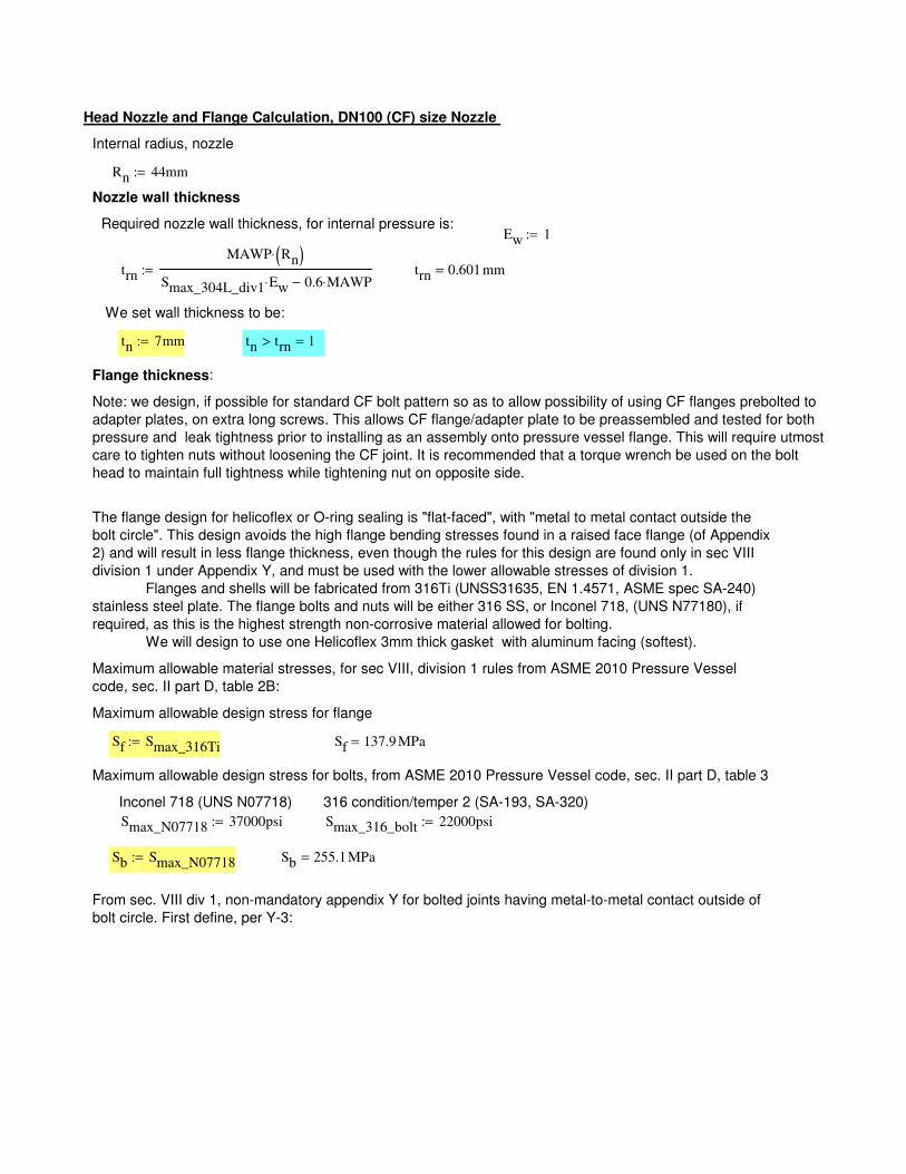
From sec. VIII div 1, non-mandatory appendix Y for bolted joints having metal-to-metal contact outside of
bolt circle. First define, per Y-3:
Sb 255.1MPa=Sb Smax_N07718:=
Smax_316_bolt 22000psi:=Smax_N07718 37000psi:=
316 condition/temper 2 (SA-193, SA-320) Inconel 718 (UNS N07718)
Maximum allowable design stress for bolts, from ASME 2010 Pressure Vessel code, sec. II part D, table 3
Sf 137.9 MPa=Sf Smax_316Ti:=
Maximum allowable design stress for flange
Maximum allowable material stresses, for sec VIII, division 1 rules from ASME 2010 Pressure Vessel
code, sec. II part D, table 2B:
The flange design for helicoflex or O-ring sealing is "flat-faced", with "metal to metal contact outside the
bolt circle". This design avoids the high flange bending stresses found in a raised face flange (of Appendix
2) and will result in less flange thickness, even though the rules for this design are found only in sec VIII
division 1 under Appendix Y, and must be used with the lower allowable stresses of division 1.
Flanges and shells will be fabricated from 316Ti (UNSS31635, EN 1.4571, ASME spec SA-240)
stainless steel plate. The flange bolts and nuts will be either 316 SS, or Inconel 718, (UNS N77180), if
required, as this is the highest strength non-corrosive material allowed for bolting.
We will design to use one Helicoflex 3mm thick gasket with aluminum facing (softest).
Note: we design, if possible for standard CF bolt pattern so as to allow possibility of using CF flanges prebolted to
adapter plates, on extra long screws. This allows CF flange/adapter plate to be preassembled and tested for both
pressure and leak tightness prior to installing as an assembly onto pressure vessel flange. This will require utmost
care to tighten nuts without loosening the CF joint. It is recommended that a torque wrench be used on the bolt
head to maintain full tightness while tightening nut on opposite side.
Flange thickness:
tn trn> 1=tn 7mm:=
We set wall thickness to be:
trn 0.601 mm=trn
MAWP Rn( )⋅
Smax_304L_div1 Ew⋅ 0.6 MAWP⋅−:=
Ew 1:=Required nozzle wall thickness, for internal pressure is:
Nozzle wall thickness
Rn 44mm:=
Internal radius, nozzle
Head Nozzle and Flange Calculation, DN100 (CF) size Nozzle

G 0.098m=G 2 Rn .5cm+( ):=
Gasket dia
C 13.0cm:=
Bolt circle (B.C.) dia, C:
B1 10.2 cm=B1 B 2g1+:=
define:
B 8.8 cm=B 2Rn:=
Flange ID
A 16.5cm:=
Flange OD
r1 3.5 mm=r1 min .5g1 5mm,( ):=g1 7 mm=g0 7 mm=g1 tn:=g0 tn:=
corner radius:hub thickness at flange (no hub)
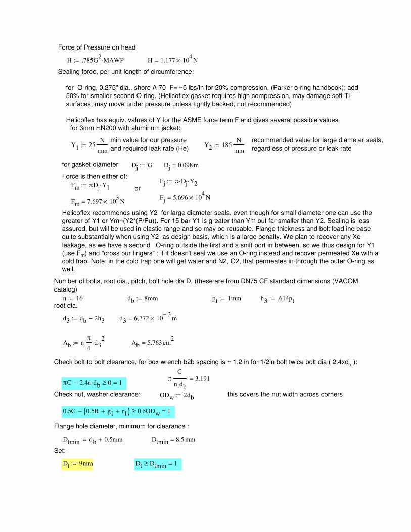
pt 1mm:= h3 .614pt:=root dia.
d3 db 2h3−:= d3 6.772 103−
× m=
Ab nπ
4⋅ d3
2⋅:= Ab 5.763 cm
2=
Check bolt to bolt clearance, for box wrench b2b spacing is ~ 1.2 in for 1/2in bolt twice bolt dia ( 2.4xdb ):
πC
n db⋅3.191=
πC 2.4n db⋅− 0≥ 1=
Check nut, washer clearance: ODw 2db:= this covers the nut width across corners
0.5C 0.5B g1+ r1+( )− 0.5ODw≥ 1=
Flange hole diameter, minimum for clearance :
Dtmin db 0.5mm+:= Dtmin 8.5 mm=
Set:
Dt 9mm:= Dt Dtmin≥ 1=
Force of Pressure on head
H .785G2
MAWP⋅:= H 1.177 104
× N=
Sealing force, per unit length of circumference:
for O-ring, 0.275" dia., shore A 70 F= ~5 lbs/in for 20% compression, (Parker o-ring handbook); add
50% for smaller second O-ring. (Helicoflex gasket requires high compression, may damage soft Ti
surfaces, may move under pressure unless tightly backed, not recommended)
Helicoflex has equiv. values of Y for the ASME force term F and gives several possible values
for 3mm HN200 with aluminum jacket:
min value for our pressure
and required leak rate (He)
recommended value for large diameter seals,
regardless of pressure or leak rateY1 25
N
mm:= Y2 185
N
mm:=
for gasket diameter Dj G:= Dj 0.098 m=
Force is then either of:Fj π Dj⋅ Y2⋅:=
Fm πDj Y1⋅:=or
Fj 5.696 104
× N=Fm 7.697 10
3× N=
Helicoflex recommends using Y2 for large diameter seals, even though for small diameter one can use the
greater of Y1 or Ym=(Y2*(P/Pu)). For 15 bar Y1 is greater than Ym but far smaller than Y2. Sealing is less
assured, but will be used in elastic range and so may be reusable. Flange thickness and bolt load increase
quite substantially when using Y2 as design basis, which is a large penalty. We plan to recover any Xe
leakage, as we have a second O-ring outside the first and a sniff port in between, so we thus design for Y1
(use Fm) and "cross our fingers" : if it doesn't seal we use an O-ring instead and recover permeated Xe with a
cold trap. Note: in the cold trap one will get water and N2, O2, that permeates in through the outer O-ring as
well.
Number of bolts, root dia., pitch, bolt hole dia D, (these are from DN75 CF standard dimensions (VACOM
catalog)
n 16:= db 8mm:=
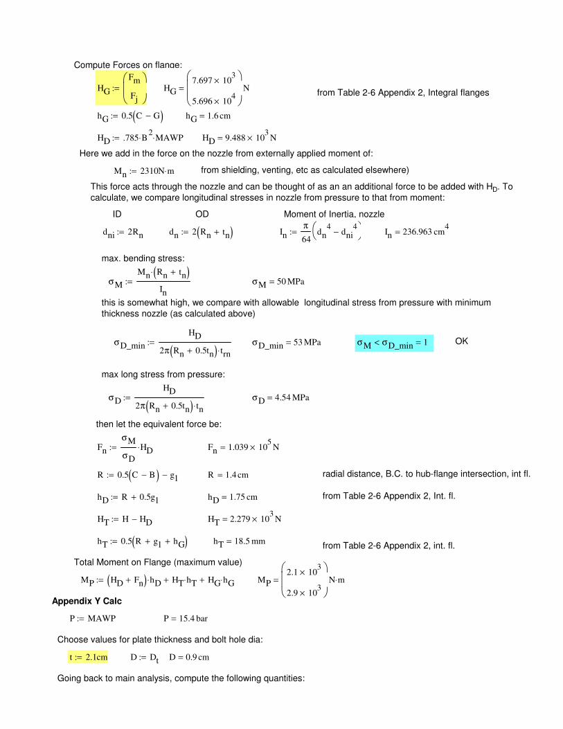
σD
HD
2π Rn 0.5tn+( ) tn⋅:= σD 4.54 MPa=
then let the equivalent force be:
Fn
σM
σD
HD⋅:= Fn 1.039 105
× N=
R 0.5 C B−( ) g1−:= R 1.4 cm= radial distance, B.C. to hub-flange intersection, int fl..
hD R 0.5g1+:= hD 1.75 cm= from Table 2-6 Appendix 2, Int. fl.
HT H HD−:= HT 2.279 103
× N=
hT 0.5 R g1+ hG+( ):= hT 18.5 mm=from Table 2-6 Appendix 2, int. fl.
Total Moment on Flange (maximum value)
MP HD Fn+( ) hD⋅ HT hT⋅+ HG hG⋅+:= MP
2.1 103
×
2.9 103
×
N m⋅=
Appendix Y Calc
P MAWP:= P 15.4 bar=
Choose values for plate thickness and bolt hole dia:
t 2.1cm:= D Dt:= D 0.9 cm=
Going back to main analysis, compute the following quantities:
Compute Forces on flange:
HG
Fm
Fj
:= HG
7.697 103
×
5.696 104
×
N=from Table 2-6 Appendix 2, Integral flanges
hG 0.5 C G−( ):= hG 1.6 cm=
HD .785 B2
⋅ MAWP⋅:= HD 9.488 103
× N=
Here we add in the force on the nozzle from externally applied moment of:
Mn 2310N m⋅:= from shielding, venting, etc as calculated elsewhere)
This force acts through the nozzle and can be thought of as an an additional force to be added with HD. To
calculate, we compare longitudinal stresses in nozzle from pressure to that from moment:
ID OD Moment of Inertia, nozzle
dni 2Rn:= dn 2 Rn tn+( ):= Inπ
64dn
4dni
4−
:= In 236.963 cm
4=
max. bending stress:
σM
Mn Rn tn+( )⋅
In
:= σM 50 MPa=
this is somewhat high, we compare with allowable longitudinal stress from pressure with minimum
thickness nozzle (as calculated above)
σD_min
HD
2π Rn 0.5tn+( ) trn⋅:= σD_min 53 MPa= σM σD_min< 1= OK
max long stress from pressure:
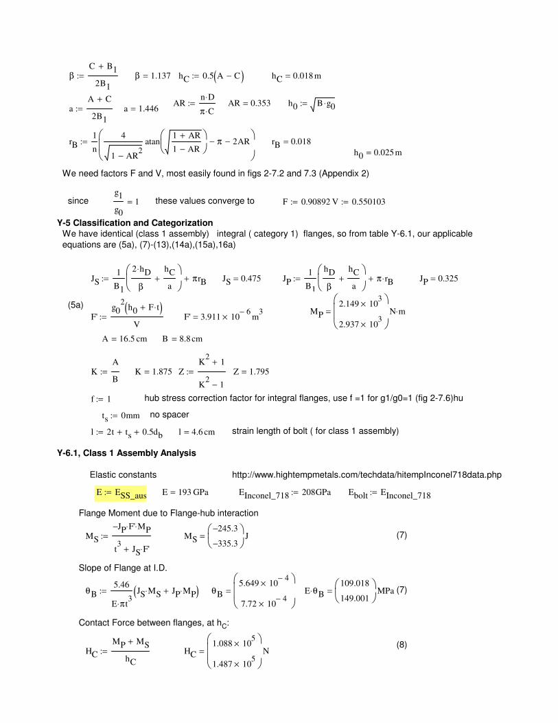
K 1.875= ZK
21+
K2
1−
:= Z 1.795=
f 1:= hub stress correction factor for integral flanges, use f =1 for g1/g0=1 (fig 2-7.6)hu
ts 0mm:= no spacer
l 2t ts+ 0.5db+:= l 4.6 cm= strain length of bolt ( for class 1 assembly)
Y-6.1, Class 1 Assembly Analysis
Elastic constants http://www.hightempmetals.com/techdata/hitempInconel718data.php
E ESS_aus:= E 193 GPa= EInconel_718 208GPa:= Ebolt EInconel_718:=
Flange Moment due to Flange-hub interaction
MS
JP− F'⋅ MP⋅
t3
JS F'⋅+
:= MS
245.3−
335.3−
J= (7)
Slope of Flange at I.D.
θB5.46
E π⋅ t3
JS MS⋅ JP MP⋅+( ):= θB
5.649 104−
×
7.72 104−
×
= E θB⋅109.018
149.001
MPa= (7)
Contact Force between flanges, at hC:
(8)HC
MP MS+
hC
:= HC
1.088 105
×
1.487 105
×
N=
βC B1+
2B1
:= β 1.137= hC 0.5 A C−( ):= hC 0.018 m=
ARn D⋅
π C⋅:= AR 0.353= h0 B g0⋅:=
aA C+
2B1
:= a 1.446=
rB1
n
4
1 AR2
−
atan1 AR+
1 AR−
π− 2AR−
:= rB 0.018=
h0 0.025m=
We need factors F and V, most easily found in figs 2-7.2 and 7.3 (Appendix 2)
since g1
g0
1= these values converge to F 0.90892:= V 0.550103:=
Y-5 Classification and Categorization
We have identical (class 1 assembly) integral ( category 1) flanges, so from table Y-6.1, our applicable
equations are (5a), (7)-(13),(14a),(15a),16a)
JS1
B1
2 hD⋅
β
hC
a+
πrB+:= JS 0.475= JP1
B1
hD
β
hC
a+
π rB⋅+:= JP 0.325=
(5a)MP
2.149 103
×
2.937 103
×
N m⋅=F'
g02
h0 F t⋅+( )V
:= F' 3.911 106−
× m3
=
A 16.5 cm= B 8.8 cm=
KA
B:=
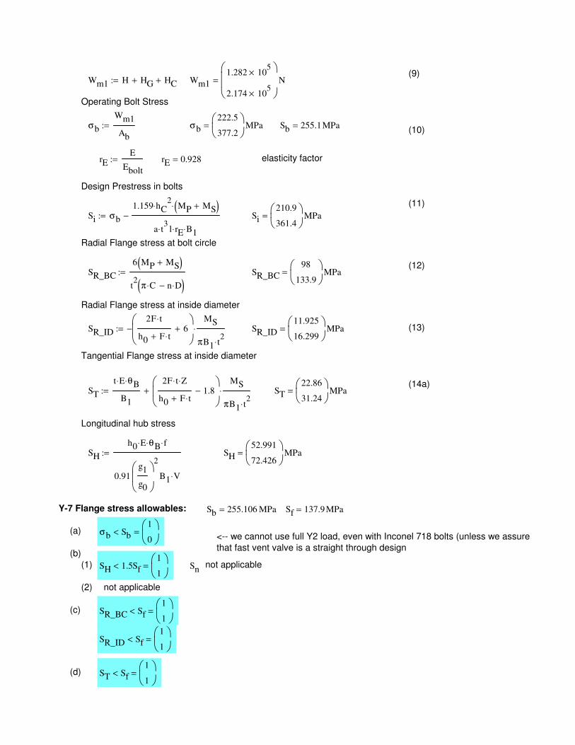
ST
t E⋅ θB⋅
B1
2F t⋅ Z⋅
h0 F t⋅+1.8−
MS
πB1 t2
⋅
⋅+:= ST
22.86
31.24
MPa=
Longitudinal hub stress
SH
h0 E⋅ θB⋅ f⋅
0.91g1
g0
2
B1 V⋅
:= SH
52.991
72.426
MPa=
Y-7 Flange stress allowables: Sb 255.106 MPa= Sf 137.9 MPa=
(a) σb Sb<1
0
=<-- we cannot use full Y2 load, even with Inconel 718 bolts (unless we assure
that fast vent valve is a straight through design(b)
(1) SH 1.5Sf<1
1
= Snnot applicable
(2) not applicable
(c) SR_BC Sf<1
1
=
SR_ID Sf<1
1
=
(d) ST Sf<1
1
=
(9)Wm1 H HG+ HC+:= Wm1
1.282 105
×
2.174 105
×
N=
Operating Bolt Stress
σb
Wm1
Ab
:= σb
222.5
377.2
MPa= Sb 255.1MPa=(10)
rEE
Ebolt
:= rE 0.928= elasticity factor
Design Prestress in bolts
(11)
Si σb
1.159 hC2
⋅ MP MS+( )⋅
a t3
⋅ l rE⋅ B1⋅
−:= Si
210.9
361.4
MPa=
Radial Flange stress at bolt circle
(12)SR_BC
6 MP MS+( )
t2
π C⋅ n D⋅−( ):= SR_BC
98
133.9
MPa=
Radial Flange stress at inside diameter
SR_ID
2F t⋅
h0 F t⋅+6+
−MS
πB1 t2
⋅
⋅:= SR_ID
11.925
16.299
MPa= (13)
Tangential Flange stress at inside diameter
(14a)
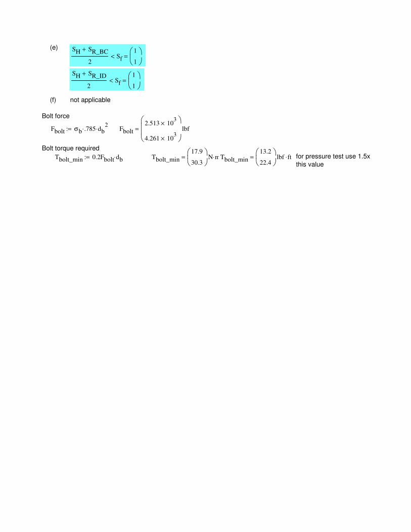
(e) SH SR_BC+
2Sf<
1
1
=
SH SR_ID+
2Sf<
1
1
=
(f) not applicable
Bolt force
Fbolt σb .785⋅ db2
⋅:= Fbolt
2.513 103
×
4.261 103
×
lbf=
Bolt torque required
Tbolt_min 0.2Fbolt db⋅:= Tbolt_min
17.9
30.3
N m⋅= Tbolt_min
13.2
22.4
lbf ft⋅= for pressure test use 1.5x
this value
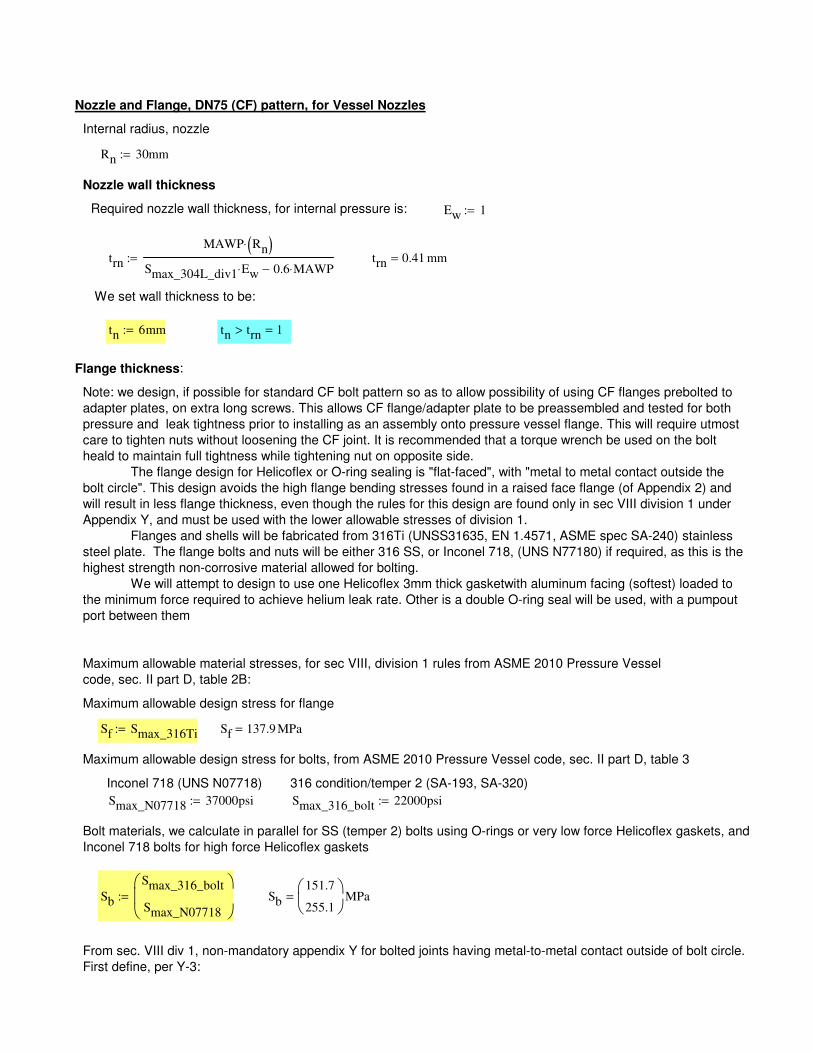
From sec. VIII div 1, non-mandatory appendix Y for bolted joints having metal-to-metal contact outside of bolt circle.
First define, per Y-3:
Sb
151.7
255.1
MPa=Sb
Smax_316_bolt
Smax_N07718
:=
Bolt materials, we calculate in parallel for SS (temper 2) bolts using O-rings or very low force Helicoflex gaskets, and
Inconel 718 bolts for high force Helicoflex gaskets
Smax_316_bolt 22000psi:=Smax_N07718 37000psi:=
316 condition/temper 2 (SA-193, SA-320) Inconel 718 (UNS N07718)
Maximum allowable design stress for bolts, from ASME 2010 Pressure Vessel code, sec. II part D, table 3
Sf 137.9 MPa=Sf Smax_316Ti:=
Maximum allowable design stress for flange
Maximum allowable material stresses, for sec VIII, division 1 rules from ASME 2010 Pressure Vessel
code, sec. II part D, table 2B:
Note: we design, if possible for standard CF bolt pattern so as to allow possibility of using CF flanges prebolted to
adapter plates, on extra long screws. This allows CF flange/adapter plate to be preassembled and tested for both
pressure and leak tightness prior to installing as an assembly onto pressure vessel flange. This will require utmost
care to tighten nuts without loosening the CF joint. It is recommended that a torque wrench be used on the bolt
heald to maintain full tightness while tightening nut on opposite side.
The flange design for Helicoflex or O-ring sealing is "flat-faced", with "metal to metal contact outside the
bolt circle". This design avoids the high flange bending stresses found in a raised face flange (of Appendix 2) and
will result in less flange thickness, even though the rules for this design are found only in sec VIII division 1 under
Appendix Y, and must be used with the lower allowable stresses of division 1.
Flanges and shells will be fabricated from 316Ti (UNSS31635, EN 1.4571, ASME spec SA-240) stainless
steel plate. The flange bolts and nuts will be either 316 SS, or Inconel 718, (UNS N77180) if required, as this is the
highest strength non-corrosive material allowed for bolting.
We will attempt to design to use one Helicoflex 3mm thick gasketwith aluminum facing (softest) loaded to
the minimum force required to achieve helium leak rate. Other is a double O-ring seal will be used, with a pumpout
port between them
Flange thickness:
tn trn> 1=tn 6mm:=
We set wall thickness to be:
trn 0.41 mm=trn
MAWP Rn( )⋅
Smax_304L_div1 Ew⋅ 0.6 MAWP⋅−:=
Ew 1:=Required nozzle wall thickness, for internal pressure is:
Nozzle wall thickness
Rn 30mm:=
Internal radius, nozzle
Nozzle and Flange, DN75 (CF) pattern, for Vessel Nozzles
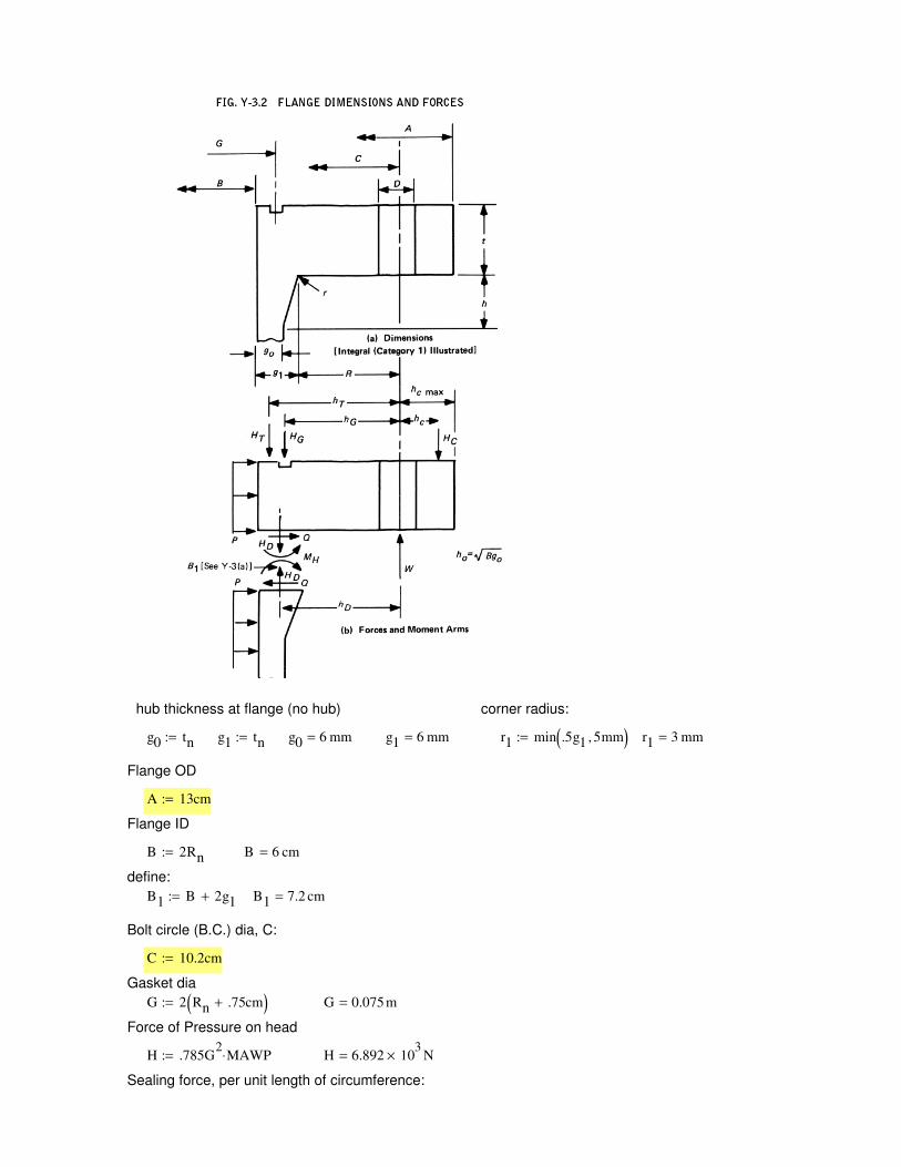
Sealing force, per unit length of circumference:
H 6.892 103
× N=H .785G2
MAWP⋅:=
Force of Pressure on head
G 0.075m=G 2 Rn .75cm+( ):=
Gasket dia
C 10.2cm:=
Bolt circle (B.C.) dia, C:
B1 7.2 cm=B1 B 2g1+:=
define:
B 6 cm=B 2Rn:=
Flange ID
A 13cm:=
Flange OD
r1 3 mm=r1 min .5g1 5mm,( ):=g1 6 mm=g0 6 mm=g1 tn:=g0 tn:=
corner radius:hub thickness at flange (no hub)
Ab 5.763 cm2
=
Check bolt to bolt clearance, for box wrench b2b spacing is 1.2 in for 1/2in bolt twice bolt dia ( 2.4xdb ):
πC 2.4n db⋅− 0≥ 1=π
C
n db⋅2.503=
Check nut, washer clearance: ODw 2db:= this covers the nut width across corners
0.5C 0.5B g1+ r1+( )− 0.5ODw≥ 1=
Flange hole diameter, minimum for clearance :
Dtmin db 0.5mm+:= Dtmin 8.5 mm=
Set:
Dt 9mm:= Dt Dtmin≥ 1=
Compute Forces on flange:
HG
Fm
Fj
:= HG
5.89 103
×
3.534 104
×
N=from Table 2-6 Appendix 2, Integral flanges
hG 0.5 C G−( ):= hG 1.35 cm=
HD .785 B2
⋅ MAWP⋅:= HD 4.411 103
× N=
Here we add in an axial force on the nozzle from the moment of a feedthrough mounted at 45 deg
for O-ring, 0.275" dia., shore A 70 F= ~5 lbs/in for 20% compression, (Parker o-ring handbook); add
50% for smaller second O-ring. (Helicoflex gasket requires high compression, may damage soft Ti
surfaces, may move under pressure unless tightly backed, not recommended)
Helicoflex has equiv. values of Y for the ASME force term F and gives several possible values
for 3mm HN200 with aluminum jacket:
min value for our pressure
and required leak rate (He)
recommended value is 185, we need to go a
bit lower for inconel 718 boltsY1 25
N
mm:= Y2 150
N
mm:=
for gasket diameter Dj G:= Dj 0.075 m=
Force is then either of:
Fm πDj Y1⋅:= Fm 5.89 103
× N=or
Fj π Dj⋅ Y2⋅:= Fj 3.534 104
× N=
Helicoflex recommends using Y2 for large diameter seals, even though for small diameter one can use the
greater of Y1 or Ym=(Y2*(P/Pu)). For 15 bar Y1 is greater than Ym but far smaller than Y2. Sealing is less
assured, but will be used in elastic range and so may be reusable. Flange thickness and bolt load increase
quite substantially when using Y2 as design basis, which is a large penalty. We plan to recover any Xe
leakage, as we have a second O-ring outside the first and a sniff port in between, so we thus design for Y1
(use Fm) and "cross our fingers" : if it doesn't seal we use an O-ring instead and recover permeated Xe with a
cold trap. Note: in the cold trap one will get water and N2, O2, that permeates in through the outer O-ring as
well.
Number of bolts, root dia., pitch, bolt hole dia D, (these are from DN75 CF standard dimensions (VACOM catalog)
n 16:= db 8mm:= pt 1mm:= h3 .614pt:=
root dia.
d3 db 2h3−:= d3 6.772 103−
× m=
Ab nπ
4⋅ d3
2⋅:=
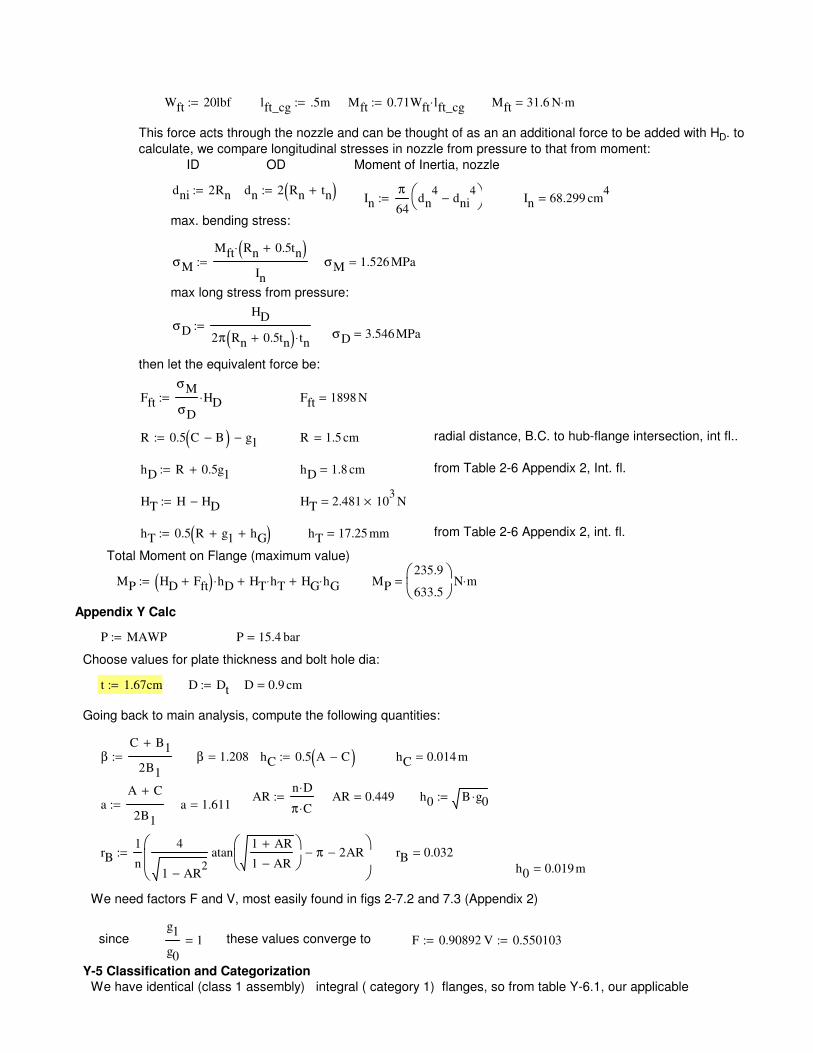
Total Moment on Flange (maximum value)
MP HD Fft+( ) hD⋅ HT hT⋅+ HG hG⋅+:= MP
235.9
633.5
N m⋅=
Appendix Y Calc
P MAWP:= P 15.4 bar=
Choose values for plate thickness and bolt hole dia:
t 1.67cm:= D Dt:= D 0.9 cm=
Going back to main analysis, compute the following quantities:
βC B1+
2B1
:= β 1.208= hC 0.5 A C−( ):= hC 0.014 m=
ARn D⋅
π C⋅:= AR 0.449= h0 B g0⋅:=
aA C+
2B1
:= a 1.611=
rB1
n
4
1 AR2
−
atan1 AR+
1 AR−
π− 2AR−
:= rB 0.032=
h0 0.019m=
We need factors F and V, most easily found in figs 2-7.2 and 7.3 (Appendix 2)
since g1
g0
1= these values converge to F 0.90892:= V 0.550103:=
Y-5 Classification and Categorization
We have identical (class 1 assembly) integral ( category 1) flanges, so from table Y-6.1, our applicable
Wft 20lbf:= lft_cg .5m:= Mft 0.71Wft lft_cg⋅:= Mft 31.6 N m⋅=
This force acts through the nozzle and can be thought of as an an additional force to be added with HD. to
calculate, we compare longitudinal stresses in nozzle from pressure to that from moment:
ID OD Moment of Inertia, nozzle
dni 2Rn:= dn 2 Rn tn+( ):=In
π
64dn
4dni
4−
:= In 68.299 cm
4=
max. bending stress:
σM
Mft Rn 0.5tn+( )⋅
In
:= σM 1.526 MPa=
max long stress from pressure:
σD
HD
2π Rn 0.5tn+( ) tn⋅:=
σD 3.546MPa=
then let the equivalent force be:
Fft
σM
σD
HD⋅:= Fft 1898 N=
R 0.5 C B−( ) g1−:= R 1.5 cm= radial distance, B.C. to hub-flange intersection, int fl..
hD R 0.5g1+:= hD 1.8 cm= from Table 2-6 Appendix 2, Int. fl.
HT H HD−:= HT 2.481 103
× N=
hT 0.5 R g1+ hG+( ):= hT 17.25 mm= from Table 2-6 Appendix 2, int. fl.
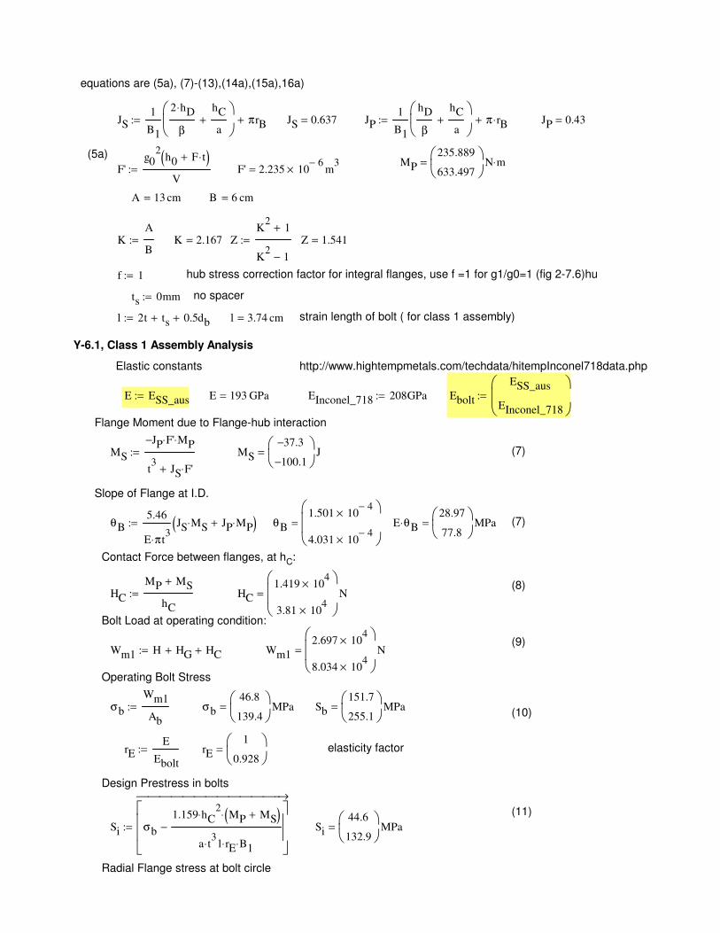
MS
JP− F'⋅ MP⋅
t3
JS F'⋅+
:= MS
37.3−
100.1−
J= (7)
Slope of Flange at I.D.
θB5.46
E π⋅ t3
JS MS⋅ JP MP⋅+( ):= θB
1.501 104−
×
4.031 104−
×
= E θB⋅28.97
77.8
MPa= (7)
Contact Force between flanges, at hC:
(8)HC
MP MS+
hC
:= HC
1.419 104
×
3.81 104
×
N=
Bolt Load at operating condition:
(9)Wm1 H HG+ HC+:= Wm1
2.697 104
×
8.034 104
×
N=
Operating Bolt Stress
σb
Wm1
Ab
:= σb
46.8
139.4
MPa= Sb
151.7
255.1
MPa=(10)
rEE
Ebolt
:= rE
1
0.928
= elasticity factor
Design Prestress in bolts
(11)
Si σb
1.159 hC2
⋅ MP MS+( )⋅
a t3
⋅ l rE⋅ B1⋅
−
→
:= Si
44.6
132.9
MPa=
Radial Flange stress at bolt circle
( )
equations are (5a), (7)-(13),(14a),(15a),16a)
JS1
B1
2 hD⋅
β
hC
a+
πrB+:= JS 0.637= JP1
B1
hD
β
hC
a+
π rB⋅+:= JP 0.43=
(5a)MP
235.889
633.497
N m⋅=F'
g02
h0 F t⋅+( )V
:= F' 2.235 106−
× m3
=
A 13 cm= B 6 cm=
KA
B:= K 2.167= Z
K2
1+
K2
1−
:= Z 1.541=
f 1:= hub stress correction factor for integral flanges, use f =1 for g1/g0=1 (fig 2-7.6)hu
ts 0mm:= no spacer
l 2t ts+ 0.5db+:= l 3.74 cm= strain length of bolt ( for class 1 assembly)
Y-6.1, Class 1 Assembly Analysis
Elastic constants http://www.hightempmetals.com/techdata/hitempInconel718data.php
E ESS_aus:= E 193 GPa= EInconel_718 208GPa:= Ebolt
ESS_aus
EInconel_718
:=
Flange Moment due to Flange-hub interaction
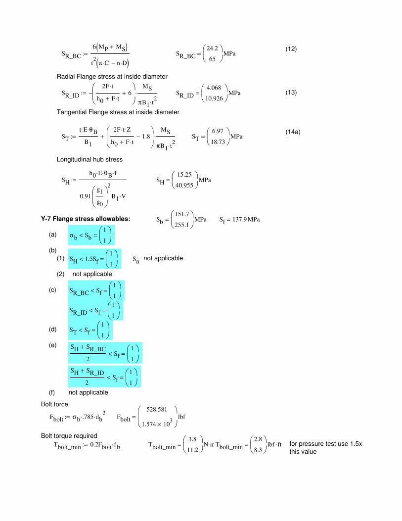
Snnot applicable
(2) not applicable
(c) SR_BC Sf<1
1
=
SR_ID Sf<1
1
=
(d) ST Sf<1
1
=
(e) SH SR_BC+
2Sf<
1
1
=
SH SR_ID+
2Sf<
1
1
=
(f) not applicable
Bolt force
Fbolt σb .785⋅ db2
⋅:= Fbolt
528.581
1.574 103
×
lbf=
Bolt torque required
Tbolt_min 0.2Fbolt db⋅:= Tbolt_min
3.8
11.2
N m⋅= Tbolt_min
2.8
8.3
lbf ft⋅= for pressure test use 1.5x
this value
(12)SR_BC
6 MP MS+( )
t2
π C⋅ n D⋅−( ):= SR_BC
24.2
65
MPa=
Radial Flange stress at inside diameter
SR_ID
2F t⋅
h0 F t⋅+6+
−MS
πB1 t2
⋅
⋅:= SR_ID
4.068
10.926
MPa= (13)
Tangential Flange stress at inside diameter
(14a)ST
t E⋅ θB⋅
B1
2F t⋅ Z⋅
h0 F t⋅+1.8−
MS
πB1 t2
⋅
⋅+:= ST
6.97
18.73
MPa=
Longitudinal hub stress
SH
h0 E⋅ θB⋅ f⋅
0.91g1
g0
2
B1 V⋅
:= SH
15.25
40.955
MPa=
Y-7 Flange stress allowables: Sb
151.7
255.1
MPa= Sf 137.9 MPa=
(a) σb Sb<1
1
=
(b)
(1) SH 1.5Sf<1
1
=
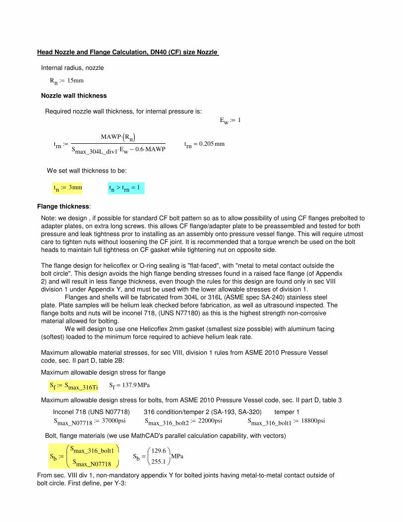
From sec. VIII div 1, non-mandatory appendix Y for bolted joints having metal-to-metal contact outside of
bolt circle. First define, per Y-3:
Sb
129.6
255.1
MPa=Sb
Smax_316_bolt1
Smax_N07718
:=
Bolt, flange materials (we use MathCAD's parallel calculation capability, with vectors)
Smax_316_bolt1 18800psi:=Smax_316_bolt2 22000psi:=Smax_N07718 37000psi:=
temper 1316 condition/temper 2 (SA-193, SA-320) Inconel 718 (UNS N07718)
Maximum allowable design stress for bolts, from ASME 2010 Pressure Vessel code, sec. II part D, table 3
Sf 137.9 MPa=Sf Smax_316Ti:=
Maximum allowable design stress for flange
Maximum allowable material stresses, for sec VIII, division 1 rules from ASME 2010 Pressure Vessel
code, sec. II part D, table 2B:
The flange design for helicoflex or O-ring sealing is "flat-faced", with "metal to metal contact outside the
bolt circle". This design avoids the high flange bending stresses found in a raised face flange (of Appendix
2) and will result in less flange thickness, even though the rules for this design are found only in sec VIII
division 1 under Appendix Y, and must be used with the lower allowable stresses of division 1.
Flanges and shells will be fabricated from 304L or 316L (ASME spec SA-240) stainless steel
plate. Plate samples will be helium leak checked before fabrication, as well as ultrasound inspected. The
flange bolts and nuts will be inconel 718, (UNS N77180) as this is the highest strength non-corrosive
material allowed for bolting.
We will design to use one Helicoflex 2mm gasket (smallest size possible) with aluminum facing
(softest) loaded to the minimum force required to achieve helium leak rate.
Note: we design , if possible for standard CF bolt pattern so as to allow possibility of using CF flanges prebolted to
adapter plates, on extra long screws. this allows CF flange/adapter plate to be preassembled and tested for both
pressure and leak tightness pror to installing as an assembly onto pressure vessel flange. This will require utmost
care to tighten nuts without loosening the CF joint. It is recommended that a torque wrench be used on the bolt
heads to maintain full tightness on CF gasket while tightening nut on opposite side.
Flange thickness:
tn trn> 1=tn 3mm:=
We set wall thickness to be:
trn 0.205 mm=trn
MAWP Rn( )⋅
Smax_304L_div1 Ew⋅ 0.6 MAWP⋅−:=
Ew 1:=
Required nozzle wall thickness, for internal pressure is:
Nozzle wall thickness
Rn 15mm:=
Internal radius, nozzle
Head Nozzle and Flange Calculation, DN40 (CF) size Nozzle
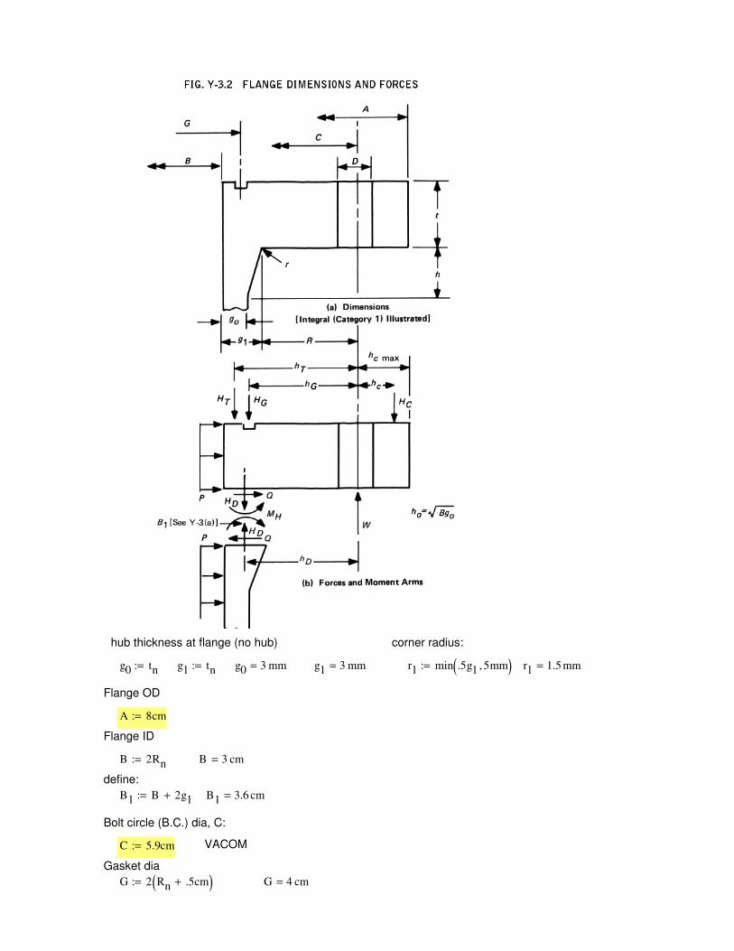
G 4 cm=G 2 Rn .5cm+( ):=
Gasket dia
VACOMC 5.9cm:=
Bolt circle (B.C.) dia, C:
B1 3.6 cm=B1 B 2g1+:=
define:
B 3 cm=B 2Rn:=
Flange ID
A 8cm:=
Flange OD
r1 1.5 mm=r1 min .5g1 5mm,( ):=g1 3 mm=g0 3 mm=g1 tn:=g0 tn:=
corner radius:hub thickness at flange (no hub)
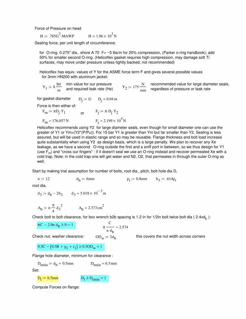
h3 .614pt:=
root dia.
d3 db 2h3−:= d3 5.018 103−
× m=
Ab nπ
4⋅ d3
2⋅:= Ab 2.373 cm
2=
Check bolt to bolt clearance, for box wrench b2b spacing is 1.2 in for 1/2in bolt twice bolt dia ( 2.4xdb ):
πC 2.0n db⋅− 0≥ 1=π
C
n db⋅2.574=
Check nut, washer clearance: ODw 2db:= this covers the nut width across corners
0.5C 0.5B g1+ r1+( )− 0.5ODw≥ 1=
Flange hole diameter, minimum for clearance :
Dtmin db 0.5mm+:= Dtmin 6.5 mm=
Set:
Dt 6.5mm:= Dt Dtmin≥ 1=
Compute Forces on flange:
Force of Pressure on head
H .785G2
MAWP⋅:= H 1.96 103
× N=
Sealing force, per unit length of circumference:
for O-ring, 0.275" dia., shore A 70 F= ~5 lbs/in for 20% compression, (Parker o-ring handbook); add
50% for smaller second O-ring. (Helicoflex gasket requires high compression, may damage soft Ti
surfaces, may move under pressure unless tightly backed, not recommended)
Helicoflex has equiv. values of Y for the ASME force term F and gives several possible values
for 3mm HN200 with aluminum jacket:
min value for our pressure
and required leak rate (He)
recommended value for large diameter seals,
regardless of pressure or leak rateY1 8
lbf
in:= Y2 175
N
mm:=
for gasket diameter Dj G:= Dj 0.04 m=
Force is then either of:
Fm πDj Y1⋅:= Fj π Dj⋅ Y2⋅:=or
Fm 176.057 N= Fj 2.199 104
× N=
Helicoflex recommends using Y2 for large diameter seals, even though for small diameter one can use the
greater of Y1 or Ym=(Y2*(P/Pu)). For 15 bar Y1 is greater than Ym but far smaller than Y2. Sealing is less
assured, but will be used in elastic range and so may be reusable. Flange thickness and bolt load increase
quite substantially when using Y2 as design basis, which is a large penalty. We plan to recover any Xe
leakage, as we have a second O-ring outside the first and a sniff port in between, so we thus design for Y1
(use Fm) and "cross our fingers" : if it doesn't seal we use an O-ring instead and recover permeated Xe with a
cold trap. Note: in the cold trap one will get water and N2, O2, that permeates in through the outer O-ring as
well.
Start by making trial assumption for number of bolts, root dia., pitch, bolt hole dia D,
n 12:= db 6mm:= pt 0.8mm:=
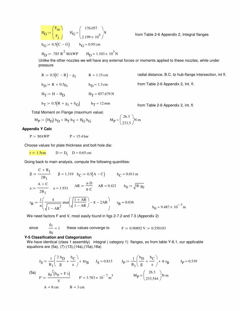
β 1.319= hC 0.5 A C−( ):= hC 0.011 m=
ARn D⋅
π C⋅:= AR 0.421= h0 B g0⋅:=
aA C+
2B1
:= a 1.931=
rB1
n
4
1 AR2
−
atan1 AR+
1 AR−
π− 2AR−
:= rB 0.036=
h0 9.487 103−
× m=
We need factors F and V, most easily found in figs 2-7.2 and 7.3 (Appendix 2)
since g1
g0
1= these values converge to F 0.90892:= V 0.550103:=
Y-5 Classification and Categorization
We have identical (class 1 assembly) integral ( category 1) flanges, so from table Y-6.1, our applicable
equations are (5a), (7)-(13),(14a),(15a),16a)
JS1
B1
2 hD⋅
β
hC
a+
πrB+:= JS 0.813= JP1
B1
hD
β
hC
a+
π rB⋅+:= JP 0.539=
(5a)MP
26.3
233.544
N m⋅=F'
g02
h0 F t⋅+( )V
:= F' 3.783 107−
× m3
=
A 8 cm= B 3 cm=
HG
Fm
Fj
:= HG
176.057
2.199 104
×
N=from Table 2-6 Appendix 2, Integral flanges
hG 0.5 C G−( ):= hG 0.95 cm=
HD .785 B2
⋅ MAWP⋅:= HD 1.103 103
× N=
Unlike the other nozzles we will have any external forces or moments applied to these nozzles, while under
pressure
R 0.5 C B−( ) g1−:= R 1.15 cm= radial distance, B.C. to hub-flange intersection, int fl..
hD R 0.5g1+:= hD 1.3 cm= from Table 2-6 Appendix 2, Int. fl.
HT H HD−:= HT 857.679 N=
hT 0.5 R g1+ hG+( ):= hT 12 mm=from Table 2-6 Appendix 2, int. fl.
Total Moment on Flange (maximum value)
MP HD( ) hD⋅ HT hT⋅+ HG hG⋅+:= MP
26.3
233.5
N m⋅=
Appendix Y Calc
P MAWP:= P 15.4 bar=
Choose values for plate thickness and bolt hole dia:
t 1.5cm:= D Dt:= D 0.65 cm=
Going back to main analysis, compute the following quantities:
βC B1+
2B1
:=
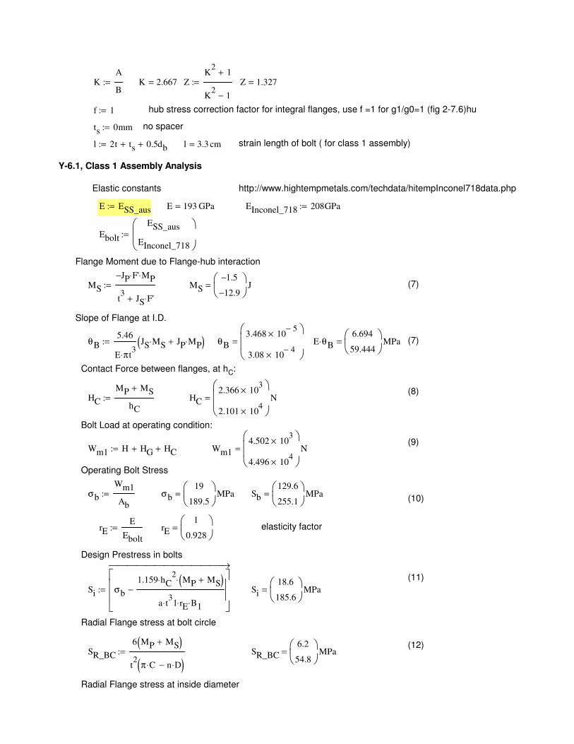
Contact Force between flanges, at hC:
(8)HC
MP MS+
hC
:= HC
2.366 103
×
2.101 104
×
N=
Bolt Load at operating condition:
(9)Wm1 H HG+ HC+:= Wm1
4.502 103
×
4.496 104
×
N=
Operating Bolt Stress
σb
Wm1
Ab
:= σb
19
189.5
MPa= Sb
129.6
255.1
MPa=(10)
rEE
Ebolt
:= rE
1
0.928
= elasticity factor
Design Prestress in bolts
(11)
Si σb
1.159 hC2
⋅ MP MS+( )⋅
a t3
⋅ l rE⋅ B1⋅
−
→
:= Si
18.6
185.6
MPa=
Radial Flange stress at bolt circle
(12)SR_BC
6 MP MS+( )
t2
π C⋅ n D⋅−( ):= SR_BC
6.2
54.8
MPa=
Radial Flange stress at inside diameter
KA
B:= K 2.667= Z
K2
1+
K2
1−
:= Z 1.327=
f 1:= hub stress correction factor for integral flanges, use f =1 for g1/g0=1 (fig 2-7.6)hu
ts 0mm:= no spacer
l 2t ts+ 0.5db+:= l 3.3 cm= strain length of bolt ( for class 1 assembly)
Y-6.1, Class 1 Assembly Analysis
Elastic constants http://www.hightempmetals.com/techdata/hitempInconel718data.php
E ESS_aus:= E 193 GPa= EInconel_718 208GPa:=
Ebolt
ESS_aus
EInconel_718
:=
Flange Moment due to Flange-hub interaction
MS
JP− F'⋅ MP⋅
t3
JS F'⋅+
:= MS
1.5−
12.9−
J= (7)
Slope of Flange at I.D.
θB5.46
E π⋅ t3
JS MS⋅ JP MP⋅+( ):= θB
3.468 105−
×
3.08 104−
×
= E θB⋅6.694
59.444
MPa= (7)
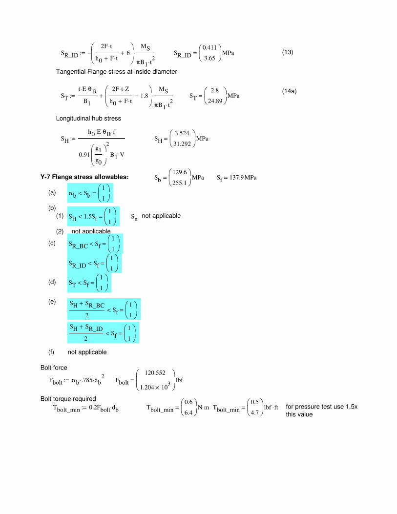
(2) not applicable
(c) SR_BC Sf<1
1
=
SR_ID Sf<1
1
=
(d) ST Sf<1
1
=
(e) SH SR_BC+
2Sf<
1
1
=
SH SR_ID+
2Sf<
1
1
=
(f) not applicable
Bolt force
Fbolt σb .785⋅ db2
⋅:= Fbolt
120.552
1.204 103
×
lbf=
Bolt torque required
Tbolt_min 0.2Fbolt db⋅:= Tbolt_min
0.6
6.4
N m⋅= Tbolt_min
0.5
4.7
lbf ft⋅= for pressure test use 1.5x
this value
SR_ID
2F t⋅
h0 F t⋅+6+
−MS
πB1 t2
⋅
⋅:= SR_ID
0.411
3.65
MPa= (13)
Tangential Flange stress at inside diameter
(14a)ST
t E⋅ θB⋅
B1
2F t⋅ Z⋅
h0 F t⋅+1.8−
MS
πB1 t2
⋅
⋅+:= ST
2.8
24.89
MPa=
Longitudinal hub stress
SH
h0 E⋅ θB⋅ f⋅
0.91g1
g0
2
B1 V⋅
:= SH
3.524
31.292
MPa=
Y-7 Flange stress allowables: Sb
129.6
255.1
MPa= Sf 137.9 MPa=
(a) σb Sb<1
1
=
(b)
(1) SH 1.5Sf<1
1
= Snnot applicable