Embed Size (px)
Citation preview
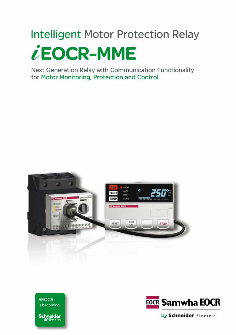
Intelligent Motor Protection Relay
Next Generation Relay with Communication Functionality for Motor Monitoring, Protection and Control


● Easy installation and maintenance for improved work efficiency
● Save time and maintenance cost
● Improve the efficiency and safety of production process
● In unmanned management system, save energy through operation statistics
● Greatly reduced space compared with the traditional panel of the same capacity
For more than 30 years since its establishment, Samhwa EOCR has
developed more than 10,000 EOCR related products including applications.
Samhwa is opening the global market with its sole expertise in EOCR that
differentiates Samhwa from other companies.
Customer Care Center 1588-3473 | www.eocr.com
Next Generation Relay with Communication Functionality for Motor Monitoring, Protec-tion and Control
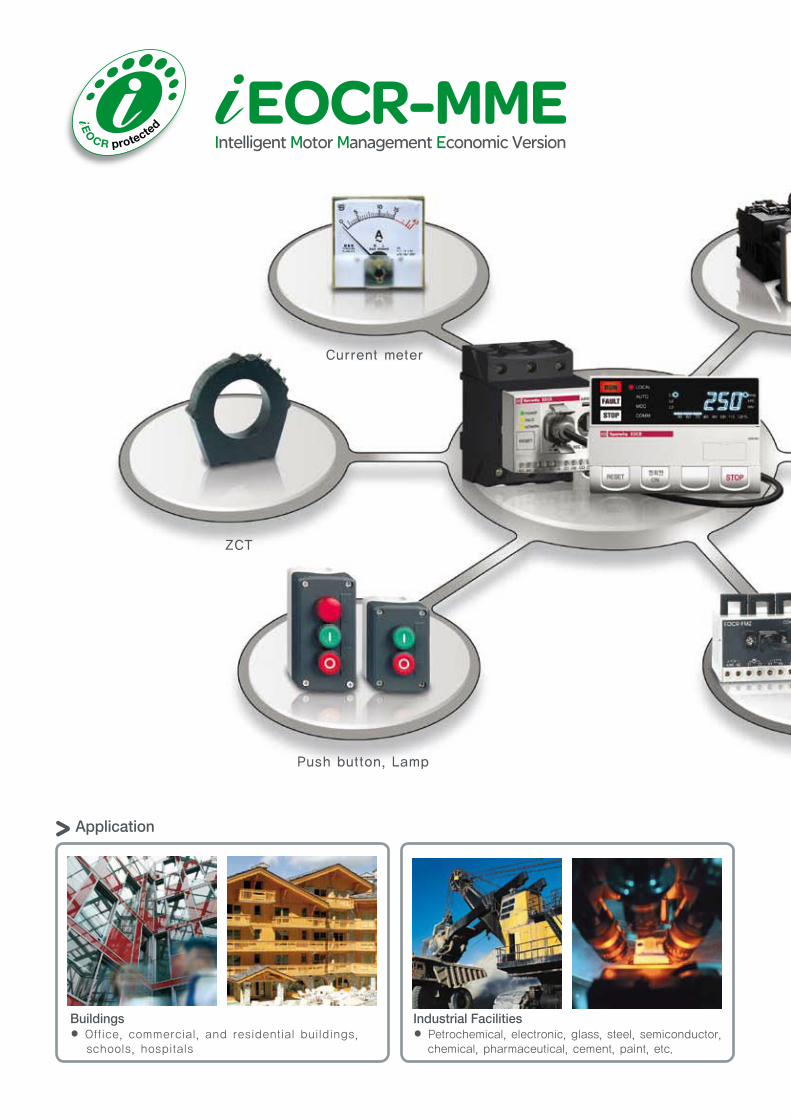
Push button, Lamp
Current meter
ZCT
Application
Buildings● Office, commercial, and residential buildings, schools, hospitals
Industrial Facilities● Petrochemical, electronic, glass, steel, semiconductor, chemical, pharmaceutical, cement, paint, etc.
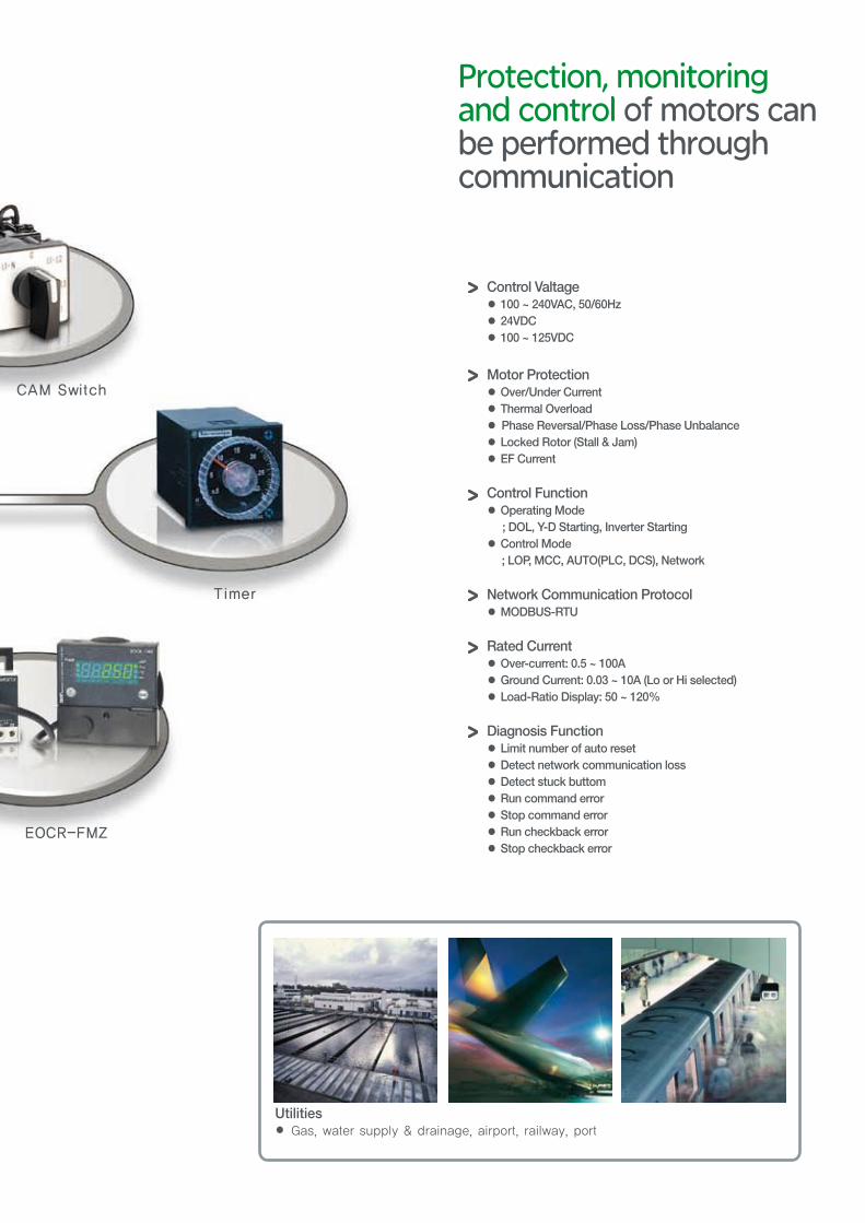
CAM Switch
Timer
EOCR-FMZ
Control Valtage● 100 ~ 240VAC, 50/60Hz● 24VDC● 100 ~ 125VDC
Motor Protection● Over/Under Current● Thermal Overload● Phase Reversal/Phase Loss/Phase Unbalance● Locked Rotor (Stall & Jam)● EF Current
Control Function● Operating Mode ; DOL, Y-D Starting, Inverter Starting● Control Mode ; LOP, MCC, AUTO(PLC, DCS), Network
Network Communication Protocol● MODBUS-RTU
Rated Current● Over-current: 0.5 ~ 100A● Ground Current: 0.03 ~ 10A (Lo or Hi selected)● Load-Ratio Display: 50 ~ 120%
Diagnosis Function● Limit number of auto reset● Detect network communication loss● Detect stuck buttom● Run command error● Stop command error● Run checkback error● Stop checkback error
Utilities● Gas, water supply & drainage, airport, railway, port
Protection, monitoring and control of motors can be performed through communication
6
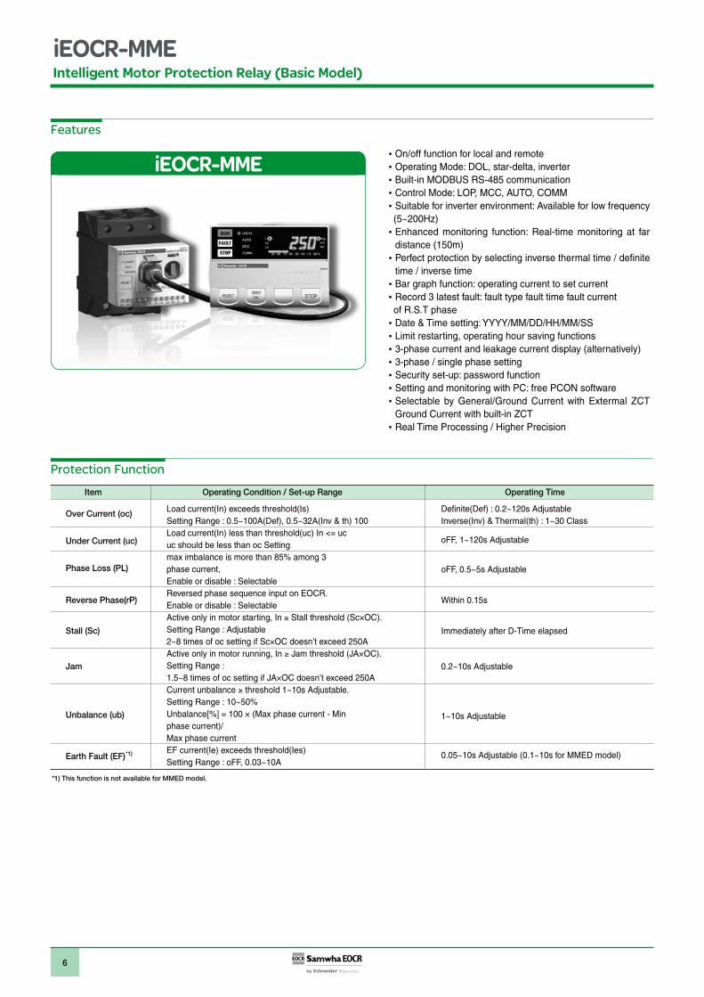
Intelligent Motor Protection Relay (Basic Model)
Features
On/off function for local and remote Operating Mode: DOL, star-delta, inverterBuilt-in MODBUS RS-485 communicationControl Mode: LOP, MCC, AUTO, COMMSuitable for inverter environment: Available for low frequency
(5~200Hz)Enhanced monitoring function: Real-time monitoring at far distance (150m)Perfect protection by selecting inverse thermal time / definite time / inverse time Bar graph function: operating current to set currentRecord 3 latest fault: fault type fault time fault current
of R.S.T phaseDate & Time setting: YYYY/MM/DD/HH/MM/SSLimit restarting, operating hour saving functions3-phase current and leakage current display (alternatively)3-phase / single phase settingSecurity set-up: password functionSetting and monitoring with PC: free PCON softwareSelectable by General/Ground Current with Extermal ZCT Ground Current with built-in ZCT Real Time Processing / Higher Precision
Protection Function
*1) This function is not available for MMED model.
Over Current (oc)
Under Current (uc)
Phase Loss (PL)
Reverse Phase(rP)
Stall (Sc)
Jam
Unbalance (ub)
Earth Fault (EF)
Item Operating Condition / Set-up Range Operating Time
Load current(In) exceeds threshold(Is) Setting Range : 0.5~100A(Def), 0.5~32A(Inv & th) 100Load current(In) less than threshold(uc) In <= ucuc should be less than oc Settingmax imbalance is more than 85% among 3phase current,Enable or disable : SelectableReversed phase sequence input on EOCR. Enable or disable : SelectableActive only in motor starting, In Stall threshold (Sc×OC).Setting Range : Adjustable 2~8 times of oc setting if Sc×OC doesn’t exceed 250AActive only in motor running, In Jam threshold (JA×OC).Setting Range : 1.5~8 times of oc setting if JA×OC doesn’t exceed 250A Current unbalance threshold 1~10s Adjustable.Setting Range : 10~50% Unbalance[%] = 100 × (Max phase current - Minphase current)/Max phase current EF current(Ie) exceeds threshold(Ies)Setting Range : oFF, 0.03~10A
Definite(Def) : 0.2~120s Adjustable Inverse(Inv) & Thermal(th) : 1~30 Class
oFF, 1~120s Adjustable
oFF, 0.5~5s Adjustable
Within 0.15s
Immediately after D-Time elapsed
0.2~10s Adjustable
1~10s Adjustable
0.05~10s Adjustable (0.1~10s for MMED model) *1)
7
Intelligent Motor Protection Relay (Basic Model)
Password
3-phase / single phase setting
Communication
Phase selection
Total Running-Hour
Running-Hour
Fault History
Limitation of autoreset attempt
Date/Time Information Setting
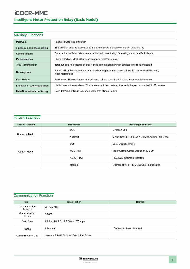
Auxiliary Functions
Communication Function
Control Function
Control Function Description Operating Conditions
Password Secure configuration
The selection enables application to 3-phase or single phase motor without urther setting
Communication Serial network communication for monitoring of metering, status, and fault history
Phase selection Select a Single-phase motor or 3-Phase motor
Total Running-Hour Record of total running from installation which cannot be modified or cleared
Running-Hour Running-Hour Accumulated running hour from preset point which can be cleared to zero, when motor stops
Fault History Records for recent 3 faults each phase current which stored in a non-volatile memory
Limitation of autoreset attempt Block auto-reset if the reset count exceeds the pre-set count within 30 minutes
Seve date/time of failure to provide exacit time of moter failure
Operating Mode
Control Mode
DOL
Y-D start
LOP
MCC (HMI)
AUTO (PLC)
Network
Direct on Line
Y start time: 0.1~999 sec, Y-D switching time: 0.0~3 sec.
Local Operation Panel
Motor Control Center, Operation by OCU
PLC, DCS automatic operation
Operation by RS-485 MODBUS communication
Item Specification Remark
CommunicationProtocol
Communication Method
Baud Rate
Range
Communication Line
Modbus RTU
RS-485
1.2, 2.4, 4.8, 9.6, 19.2, 38.4 AUTO kbps
1.2km max.
Universal RS-485 Shielded Twist 2-Pair Cable
Depend on the environment
8
Intelligent Motor Protection Relay (Basic Model)
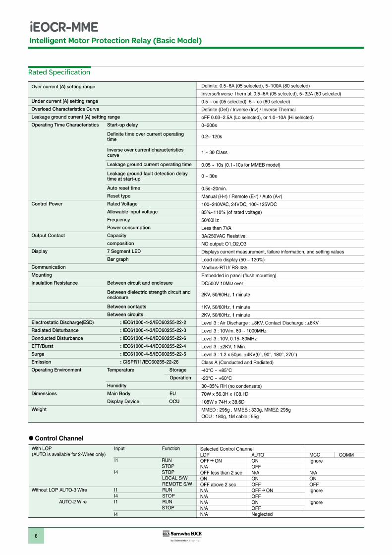
Rated Specification
Over current (A) setting range
Under current (A) setting range
Overload Characteristics Curve
Leakage ground current (A) setting range
Operating Time Characteristics Start-up delay
Definite time over current operating time
Inverse over current characteristicscurve
Leakage ground current operating time
Leakage ground fault detection delay time at start-up
Auto reset time
Reset type
Control Power Rated Voltage
Allowable input voltage
Frequency
Power consumption
Output Contact Capacity
composition
Display 7 Segment LED
Bar graph
Communication
Mounting
Insulation Resistance Between circuit and enclosure
Between dielectric strength circuit and enclosure
Between contacts
Between circuits
Electrostatic Discharge(ESD) : IEC61000-4-2/IEC60255-22-2
Radiated Disturbance : IEC61000-4-3/IEC60255-22-3
Conducted Disturbance : IEC61000-4-6/IEC60255-22-6
EFT/Burst : IEC61000-4-4/IEC60255-22-4
Surge : IEC61000-4-5/IEC60255-22-5
Emission : CISPR11/IEC60255-22-26
Operating Environment Temperature Storage
Operation
Humidity
Dimensions Main Body EU
Display Device OCU
Weight
With LOP Input Function (AUTO is available for 2-Wires only) I1 RUN STOP
I4 STOP LOCAL S/W REMOTE S/W Without LOP AUTO-3 Wire I1 RUN I4 STOP AUTO-2 Wire I1 RUN STOP
I4
Control Channel
Definite: 0.5~6A (05 selected), 5~100A (80 selected)
Inverse/Inverse Thermal: 0.5~6A (05 selected), 5~32A (80 selected)
0.5 ~ oc (05 selected), 5 ~ oc (80 selected)
Definite (Def) / Inverse (Inv) / Inverse Thermal
oFF 0.03~2.5A (Lo selected), or 1.0~10A (Hi selected)
0~200s
0.2~ 120s
1 ~ 30 Class
0.05 ~ 10s (0.1~10s for MMEB model)
0 ~ 30s
0.5s~20min.
Manual (H-r) / Remote (E-r) / Auto (A-r)
100~240VAC, 24VDC, 100~125VDC
85%~110% (of rated voltage)
50/60Hz
Less than 7VA
3A/250VAC Resistive.
NO output: O1,O2,O3
Displays current measurement, failure information, and setting values
Load ratio display (50 ~ 120%)
Modbus-RTU/ RS-485
Embedded in panel (flush mounting)
DC500V 10M over
2KV, 50/60Hz, 1 minute
1KV, 50/60Hz, 1 minute
2KV, 50/60Hz, 1 minute
Level 3 : Air Discharge : ±8KV, Contact Discharge : ±6KV
Level 3 : 10V/m, 80 ~ 1000MHz
Level 3 : 10V, 0.15~80MHz
Level 3 : ±2KV, 1 Min
Level 3 : 1.2 x 50μs, ±4KV(0°, 90°, 180°, 270°)
Class A (Conducted and Radiated)
-40°C ~ +85°C
-20°C ~ +60°C
30~85% RH (no condensate)
70W x 56.3H x 108.1D
108W x 74H x 38.6D
MMED : 295g , MMEB : 330g, MMEZ: 295gOCU : 180g, 1M cable : 55g
Selected Control ChannelLOP AUTO MCC COMMOFF ON ON IgnoreN/A OFFOFF less than 2 sec N/A N/AON ON ONOFF above 2 sec OFF OFFN/A OFF ON IgnoreN/A OFFN/A ON IgnoreN/A OFFN/A Neglected
9
Intelligent Motor Protection Relay (Basic Model)
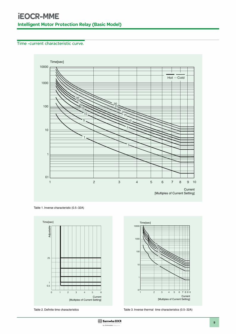
Time -current characteristic curve.
Table 2. Definite time characteristics Table 3. Inverse thermal time characteristics (0.5~32A)
Table 1. Inverse characteristic (0.5~32A)
10
Intelligent Motor Protection Relay (Basic Model)
Over current and time setting tips
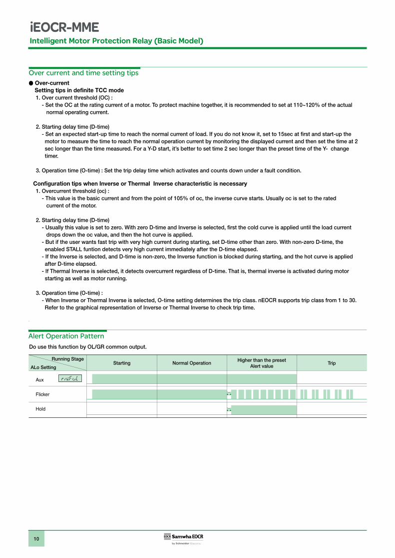
Aux
Flicker
Hold
Normal OperationStartingRunning Stage
ALo SettingHigher than the preset
Alert valueTrip
Alert Operation Pattern Do use this function by OL/GR common output.
Over-current Setting tips in definite TCC mode
1. Over current threshold (OC) :- Set the OC at the rating current of a motor. To protect machine together, it is recommended to set at 110~120% of the actual
normal operating current.
2. Starting delay time (D-time)- Set an expected start-up time to reach the normal current of load. If you do not know it, set to 15sec at first and start-up the
motor to measure the time to reach the normal operation current by monitoring the displayed current and then set the time at 2 sec longer than the time measured. For a Y-D start, it’s better to set time 2 sec longer than the preset time of the Y- change timer.
3. Operation time (O-time) : Set the trip delay time which activates and counts down under a fault condition.
Configuration tips when Inverse or Thermal Inverse characteristic is necessary 1. Overcurrent threshold (oc) :
- This value is the basic current and from the point of 105% of oc, the inverse curve starts. Usually oc is set to the rated current of the motor.
2. Starting delay time (D-time)- Usually this value is set to zero. With zero D-time and Inverse is selected, first the cold curve is applied until the load current
drops down the oc value, and then the hot curve is applied.- But if the user wants fast trip with very high current during starting, set D-time other than zero. With non-zero D-time, the
enabled STALL funtion detects very high current immediately after the D-time elapsed.- If the Inverse is selected, and D-time is non-zero, the Inverse function is blocked during starting, and the hot curve is applied
after D-time elapsed.- If Thermal Inverse is selected, it detects overcurrent regardless of D-time. That is, thermal inverse is activated during motor
starting as well as motor running.
3. Operation time (O-time) : - When Inverse or Thermal Inverse is selected, O-time setting determines the trip class. nEOCR supports trip class from 1 to 30.
Refer to the graphical representation of Inverse or Thermal Inverse to check trip time.
.
1sec
1sec
11
Intelligent Motor Protection Relay (Basic Model)
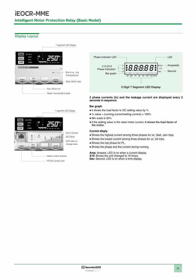
Display Layout
7 segment LED Display
7 segment LED Display
Marking tag(Transparency)
SET/Store
Stop: Motor stop
Reset: manual failure reset
PCON connect port
Select control channel
Shift menu or change value
Exit or Cancel
Run: Motor run
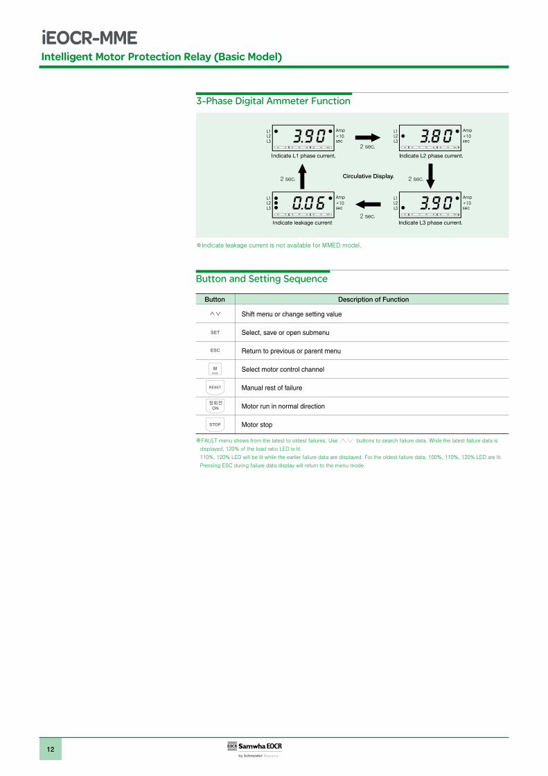
3 phase currents (In) and the leakage current are displayed every 2 seconds in sequence.
Bar graphit shows the load factor to OC setting value by %% value = (running current/setting current) × 100%Min scale is 50%if the setting value is the rated motor current, it shows the load factor of
the motor.
Current displyShows the highest current among three phases for oc, Stall, Jam trips. Shows the lowest current among three phases for uc, Ub trips. Shows the lost phase for PL.Shows the phase and the current during running.
Amp: Ampere. LED is on when a current display. X10: Shows the unit changed to 10 times. Sec: Second. LED is on when a time display.
12
Intelligent Motor Protection Relay (Basic Model)
3-Phase Digital Ammeter Function
Button and Setting Sequence
STOP
RESET
MMODE
ESC
SET
Shift menu or change setting value
Select, save or open submenu
Return to previous or parent menu
Select motor control channel
Manual rest of failure
Motor run in normal direction
Motor stop
Button Description of Function
13
Intelligent Motor Protection Relay (Basic Model)
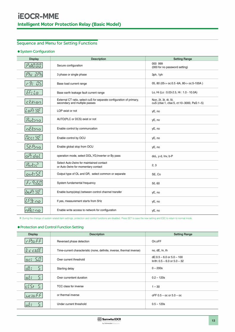
Sequence and Menu for Setting Functions
System Configuration
Display Description Setting Range
Secure configuration
3 phase or single phase
Base load current range
Base earth leakage fault current range
External CT ratio, select cuS for separate configuration of primary,secondary and multiple passes
LOP exist or not
AUTO(PLC or DCS) exist or not
Enable control by communcation
Enable control by OCU
Enable global stop from OCU
operation mode, select DOL,YD,Inverter or By pass
Select Auto-2wire for maintained contact or Auto-3wire for momentary contact
Output type of OL and GR, select common or separate
System fundamental frequency
Enable bump(stop) between control channel transfer
lf yes, measurement starts from 5Hz
Enable write access to network for configuration
000 999(000 for no password setting)
3ph, 1ph
05, 80 (05-> oc:0.5 -6A, 80-> oc:5-100A )
Lo, Hi (Lo : 0.03-2.5, Hi : 1.0 - 10.0A)
Non, 2t, 3t, 4t, 5t,cuS (ctse:1, ctse:5, ct:10~3000, PaS:1~5)
yE, no
yE, no
yE, no
yE, no
yE, no
doL, y-d, Inv, b-P
2, 3
SE, Co
50, 60
yE, no
yE, no
yE, no
Reversed phase detection
Time-current characteristic (none, definite, inverse, thermal inverse)
Over current threshold
Starting delay
Over currentent duration
TCC class for inverse
or thermal inverse
Under current threshold
Protection and Control Function Setting
Display Description Setting Range
On,oFF
no, dE, In, th
dE:0.5 – 6.0 or 5.0 – 100 ln/th: 0.5 – 6.0 or 5.0 – 32
0 – 200s
0.2 – 120s
1 – 30
oFF 0.5 – oc or 5.0 – oc
0.5 – 120s
14
Intelligent Motor Protection Relay (Basic Model)
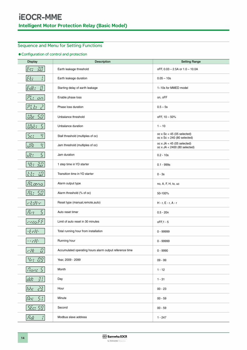
Sequence and Menu for Setting Functions
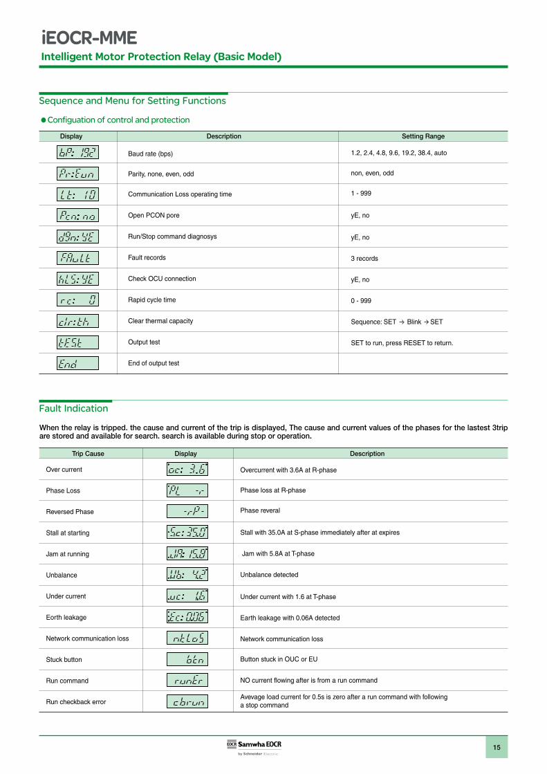
Configuration of control and protection
Display Description Setting Range
Earth leakage threshold
Earth leakage duration
Starting delay of earth leakage
Enable phase loss
Phase loss duration
Unbalance threshold
Unbalance duration
Stall threshold (multiples of oc)
Jam threshold (multiples of oc)
Jam duration
1 step time in YD starter
Transition time in YD starter
Alarm output type
Alarm threshold (% of oc)
Reset type (manual,remote,auto)
Auto reset timer
Limit of auto reset in 30 minutes
Total running hour from installation
Running hour
Accumulated operating hours alarm output reference time
Year, 2009 - 2099
Month
Day
Hour
Minute
Second
Modbus slave address
oFF, 0.03 – 2.5A or 1.0 – 10.0A
0.05 – 10s
1~10s for MMED model
on, oFF
0.5 – 5s
oFF, 10 – 50%
1 – 10
oc x Sc < 45 (05 selected)oc x Sc < 240 (80 selected)
oc x JA < 45 (05 selected)oc x JA < 2400 (80 selected)
0.2 - 10s
0.1 - 999s
0 - 3s
no, A, F, H, to, uc
50-100%
H - r, E - r, A - r
0.5 - 20n
oFF,1 - 5
0 - 99999
0 - 99999
0 - 9990
09 - 99
1 - 12
1 - 31
00 - 23
00 - 59
00 - 59
1 - 247
15
Intelligent Motor Protection Relay (Basic Model)
Sequence and Menu for Setting Functions
Configuation of control and protection
Fault Indication
When the relay is tripped. the cause and current of the trip is displayed, The cause and current values of the phases for the lastest 3trip are stored and available for search. search is available during stop or operation.
Over current
Phase Loss
Reversed Phase
Stall at starting
Jam at running
Unbalance
Under current
Eorth leakage
Network communication loss
Stuck button
Run command
Run checkback error
Display Description Setting Range
Baud rate (bps)
Parity, none, even, odd
Communication Loss operating time
Open PCON pore
Run/Stop command diagnosys
Fault records
Check OCU connection
Rapid cycle time
Clear thermal capacity
Output test
End of output test
1.2, 2.4, 4.8, 9.6, 19.2, 38.4, auto
non, even, odd
1 - 999
yE, no
yE, no
3 records
yE, no
0 - 999
Sequence: SET Blink SET
SET to run, press RESET to return.
Display Description
Overcurrent with 3.6A at R-phase
Phase loss at R-phase
Phase reveral
Stall with 35.0A at S-phase immediately after at expires
Jam with 5.8A at T-phase
Unbalance detected
Under current with 1.6 at T-phase
Earth leakage with 0.06A detected
Network communication loss
Button stuck in OUC or EU
NO current flowing after is from a run command
Avevage load current for 0.5s is zero after a run command with following a stop command
Trip Cause
16
Intelligent Motor Protection Relay (Basic Model)
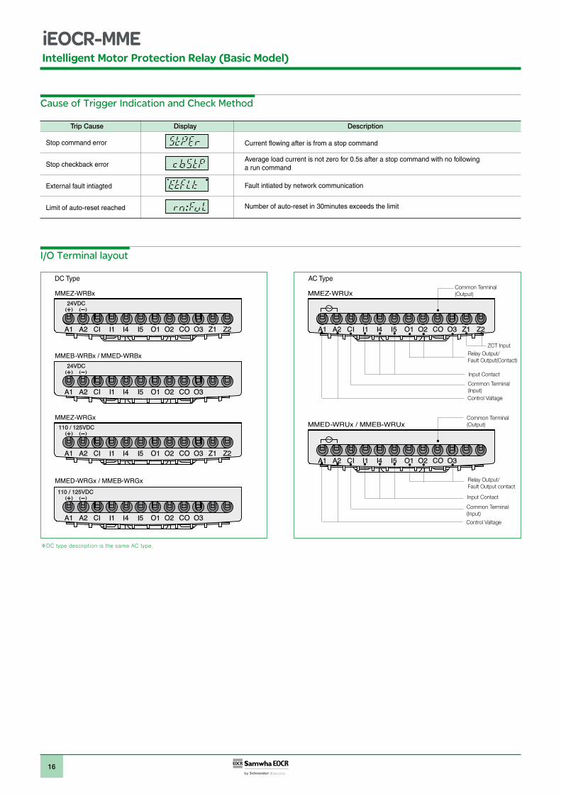
AC Type
Cause of Trigger Indication and Check Method
I/O Terminal layout
DC TypeCommon Terminal (Output)
ZCT Input
Relay Output/Fault Output contact
Relay Output/Fault Output(Contact)
Input Contact
Common Terminal (Input)Control Valtage
Display Description
Stop command error
Stop checkback error
External fault intiagted
Limit of auto-reset reached
Current flowing after is from a stop command
Average load current is not zero for 0.5s after a stop command with no following a run command
Fault intiated by network communication
Number of auto-reset in 30minutes exceeds the limit
Common Terminal (Output)
Control Valtage
Common Terminal (Input)
Input Contact
Trip Cause
17
Intelligent Motor Protection Relay (Basic Model)
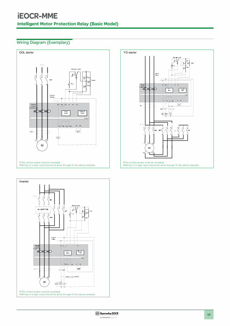
Wiring Diagram (Exemplary)
P3-EU
3
Internal Current
Transformers
Z1 Z2
A1 A2 I1CI I4 I5
O2 CO
ZCTZCT
OCURJ45
KM1
ControlSupply
Start
Stop
KM1
UV W
O1 O3
Reset
LocalRemote
NetworkRJ45
PLC
2
34
56
12
34
56
1 2
34
56
1DOL starter Y-D starter
Inverter
18
Intelligent Motor Protection Relay (Basic Model)
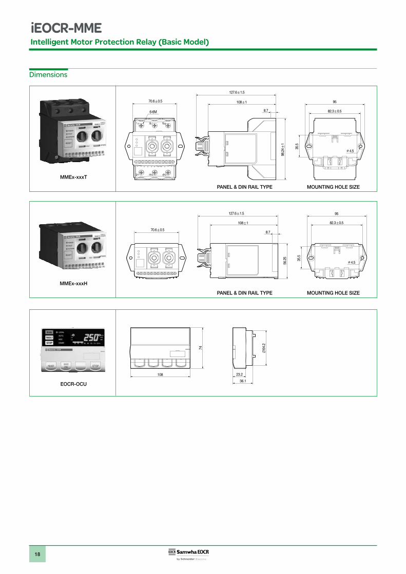
Dimensions
82.3 0.5
70.6 0.5 108 1
127.6 1.5
6-6M
98.2
41
35.5
95
8.7
4.5
PANEL & DIN RAIL TYPE MOUNTING HOLE SIZE
8.7
4.5
82.3 0.5
70.6 0.5
108 1
127.6 1.5
35.5
56.2
5
95
PANEL & DIN RAIL TYPE MOUNTING HOLE SIZE
108 23.2
36.1
74
MMEx-xxxT
MMEx-xxxH
EOCR-OCU
19
Intelligent Motor Protection Relay (Basic Model)
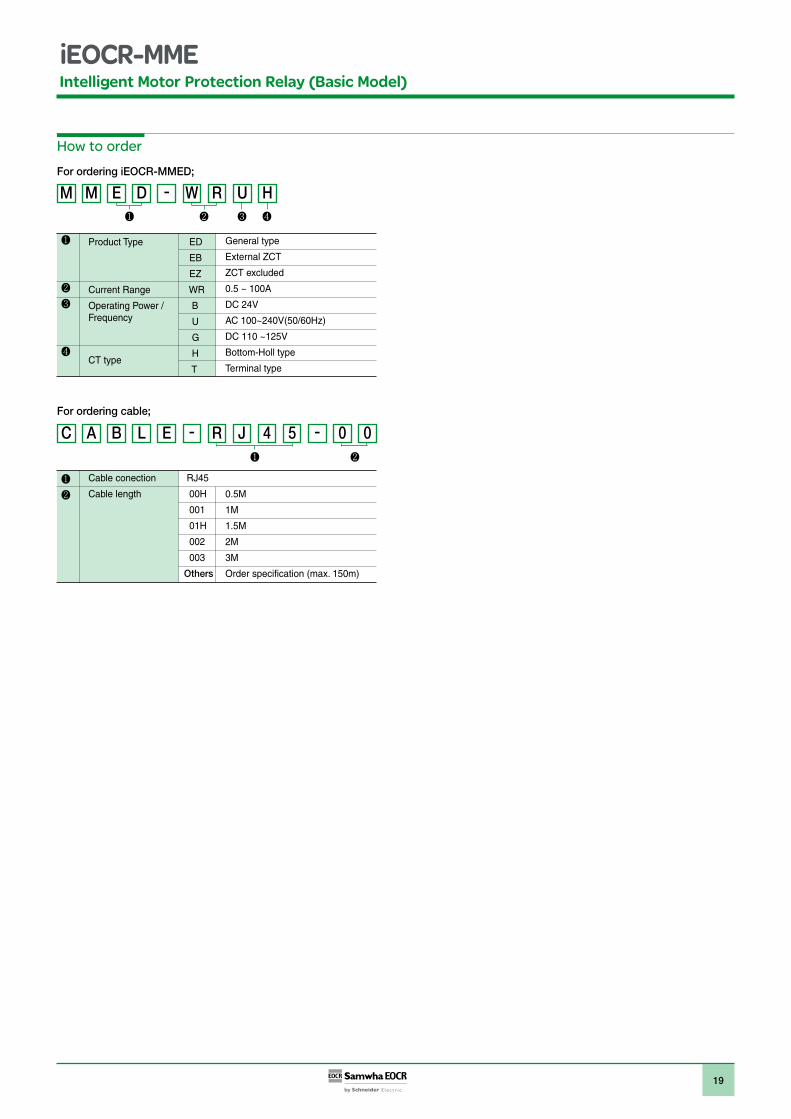
How to order
For ordering iEOCR-MMED;
For ordering cable;
Product Type ED
EB
EZ
Current Range WR
Operating Power / BFrequency U
G
CT type H
T
General type
External ZCT
ZCT excluded
0.5 ~ 100A
DC 24V
AC 100~240V(50/60Hz)
DC 110 ~125V
Bottom-Holl type
Terminal type
Cable conection RJ45
Cable length 00H
001
01H
002
003
Others
0.5M
1M
1.5M
2M
3M
Order specification (max. 150m)
Intelligent Motor Protection Relay (Basic Model)
20
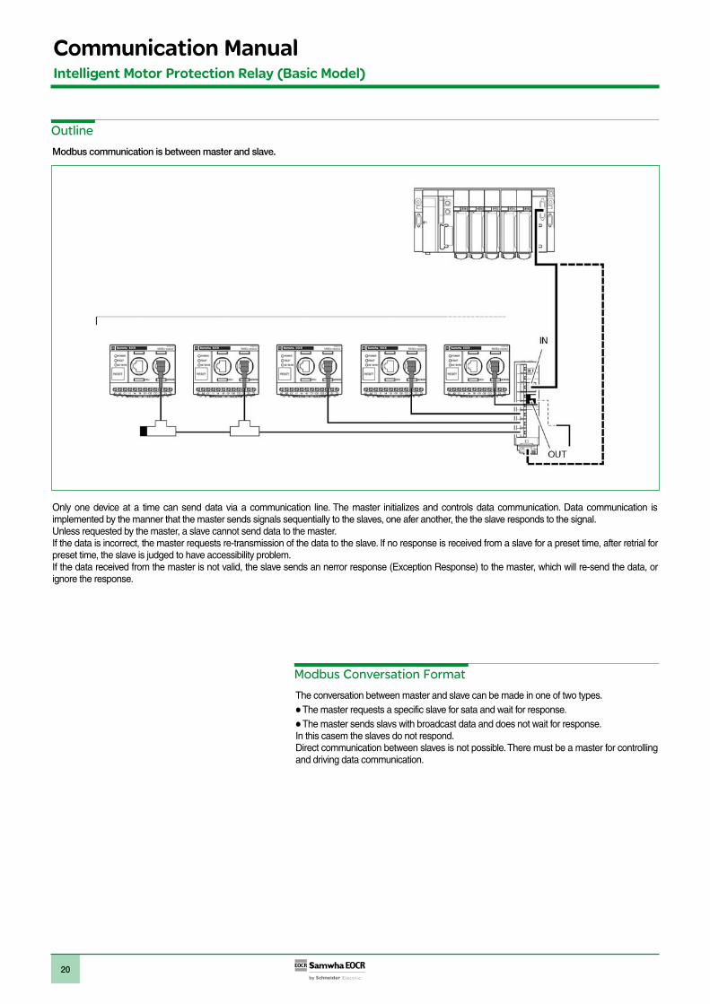
Outline
Modbus communication is between master and slave.
Modbus Conversation Format
The conversation between master and slave can be made in one of two types.The master requests a specific slave for sata and wait for response.The master sends slavs with broadcast data and does not wait for response.
In this casem the slaves do not respond.Direct communication between slaves is not possible. There must be a master for controlling and driving data communication.
Only one device at a time can send data via a communication line. The master initializes and controls data communication. Data communication is implemented by the manner that the master sends signals sequentially to the slaves, one afer another, the the slave responds to the signal.Unless requested by the master, a slave cannot send data to the master.If the data is incorrect, the master requests re-transmission of the data to the slave. If no response is received from a slave for a preset time, after retrial for preset time, the slave is judged to have accessibility problem.If the data received from the master is not valid, the slave sends an nerror response (Exception Response) to the master, which will re-send the data, or ignore the response.
Communication Manual
21
Communication Setting ValuePlease set the modbus communication parameters by PCONTM or HMI for the communication
Slave AddressBaud rateParity bitCommunication loss timeout
Slave AddressThe EOCR has slave address from 1 to 247.The factory default setting is1.
Baud rateThe commuincation speed provided is like below
1.2kbps2.4kbps4.8kbps9.6kbps19.2kbps38.4kbps
Factory setting is 19.2kbps.
Parity Bit settingEvenOddNone
Factory setting is Even. Parity and stop bit have following relationship.
Modbus Network Set-up
Parity
Even or Odd
None
RS485 Bus Connection
RS485 standard allows several different characteristics.PolarizationLine TerminatorNumber of SlavesLength of the bus
There is a definition of Modbus presented in detail at the website of Modbus.org in 2002. Standard connection.
Stop Bit
1
2
Communication loss timeoutIt is the criteria to confirm the communication disconnection with a master like as PLC. EOCR judges it as a communication disconnection error, if there is no call from the master during a certain preset time. The time setting range is 1~999sec the factory default setting is OFF. The OFF means no communication error check. It is advised to set it at OFF, if there is no concern of communication disconnection or no needs of communication error check at ordinary times.
Communication Manual
22
Intelligent Motor Protection Relay (Basic Model)
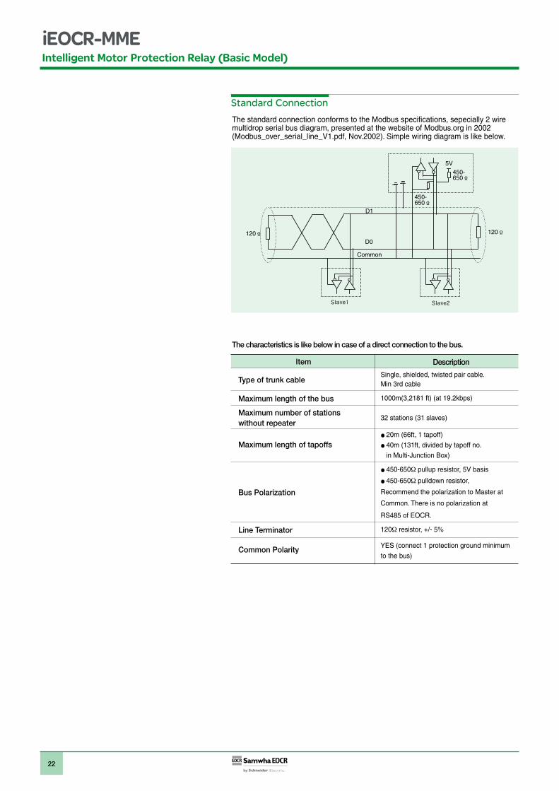
The standard connection conforms to the Modbus specifications, sepecially 2 wire multidrop serial bus diagram, presented at the website of Modbus.org in 2002(Modbus_over_serial_line_V1.pdf, Nov.2002). Simple wiring diagram is like below.
The characteristics is like below in case of a direct connection to the bus.
Standard Connection
120 120
450-650
5V
450-650
D1
D0
Common
Item Description
Single, shielded, twisted pair cable.Min 3rd cable
1000m(3,2181 ft) (at 19.2kbps)
32 stations (31 slaves)
20m (66ft, 1 tapoff)
40m (131ft, divided by tapoff no.
in Multi-Junction Box)
450-650 pullup resistor, 5V basis
450-650 pulldown resistor,
Recommend the polarization to Master at
Common. There is no polarization at
RS485 of EOCR.
120 resistor, +/- 5%
YES (connect 1 protection ground minimum
to the bus)
Type of trunk cable
Maximum length of the bus
Maximum number of stations without repeater
Maximum length of tapoffs
Bus Polarization
Line Terminator
Common Polarity
23
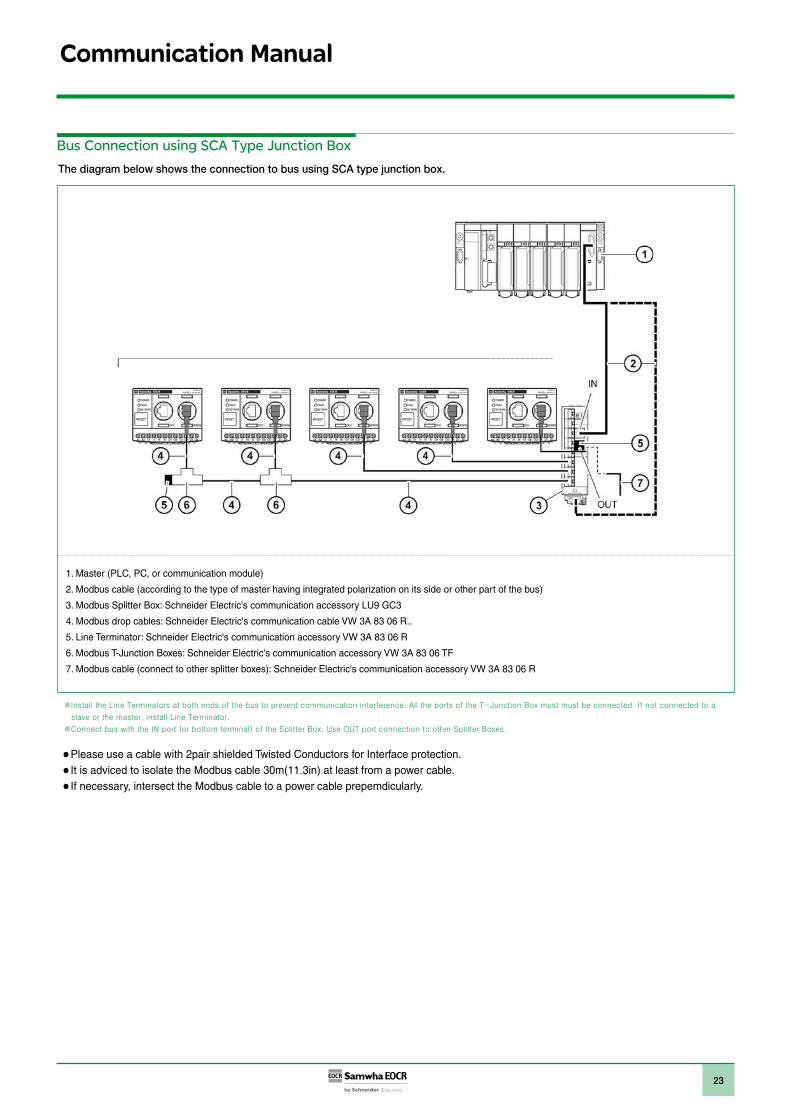
The diagram below shows the connection to bus using SCA type junction box.
Bus Connection using SCA Type Junction Box
1. Master (PLC, PC, or communication module)
2. Modbus cable (according to the type of master having integrated polarization on its side or other part of the bus)
3. Modbus Splitter Box: Schneider Electric's communication accessory LU9 GC3
4. Modbus drop cables: Schneider Electric's communication cable VW 3A 83 06 R..
5. Line Terminator: Schneider Electric's communication accessory VW 3A 83 06 R
6. Modbus T-Junction Boxes: Schneider Electric's communication accessory VW 3A 83 06 TF
7. Modbus cable (connect to other splitter boxes): Schneider Electric's communication accessory VW 3A 83 06 R
Communication Manual
Please use a cable with 2pair shielded Twisted Conductors for Interface protection.It is adviced to isolate the Modbus cable 30m(11.3in) at least from a power cable.If necessary, intersect the Modbus cable to a power cable prepemdicularly.

EO
CR
CAT
_EN
ⓒ 2
010
Sam
wha
EO
CR
Ltd
.-A
ll ri
ght
s re
serv
ed.
Head Office6th floor, Jeil Bldg., 94-46, Youngdeungpo-Dong 7Ka, Youngdeungpo-Ku, Seoul, KoreaTel. 82 2 3473 2340 / Fax 82 2 3473 1159Iksan Plant574, Yongie-dong, Iksan-shi, Junbuk, KoreaTel. 82 63 835 5033 / Fax 82 63 835 4175www.eocr.com 06/2010