Embed Size (px)
Citation preview

EPLAN NEWSfor Version 2.2

Copyright © 2012 EPLAN Software & Service GmbH & Co. KG
EPLAN Software & Service GmbH & Co. KG assumes no liability for either technical or printing errors, orfor deficiencies in this technical information and cannot be held liable for damages that may result directlyor indirectly from the delivery, performance, and use of this material.
This document contains legally protected proprietary information that is subject to copyright. All rights areprotected. This document or parts of this document may not be copied or reproduced by any other meanswithout the prior consent of EPLAN Software & Service GmbH & Co. KG.
The software described in this document is subject to a licensing agreement. The use and reproduction ofthe software is only permitted within the framework of this agreement.
RITTAL® is a registered trademark of Rittal GmbH & Co. KG.
EPLAN®, EPLAN Electric P8®, EPLAN Fluid®, EPLAN PPE®, EPLAN Cabinet®, EPLAN Pro Panel® andEPLAN Mechatronic Integration® are registered trademarks of EPLAN Software & Service GmbH & Co.KG.
Windows NT®, Windows 2000®, Windows XP®, Windows Vista®, Windows 7®, Microsoft Windows®,Microsoft® Excel®, Microsoft® Access® and Notepad® are registered trademarks of theMicrosoft Cor-poration.
PC WORX®, CLIP PROJECT®, and INTERBUS® are registered trademarks of Phoenix Contact GmbH& Co.
AutoCAD® and AutoCAD Inventor® are registered trademarks of Autodesk, Inc.
STEP 7®, SIMATIC® and SIMATIC HW Konfig.® are registered trademarks of Siemens AG.
InstallShield® is a registered trademark of InstallShield, Inc.
Adobe®Reader® and Adobe® Acrobat® are registered trademarks of Adobe Systems Inc.
TwinCAT® is a registered trademark of Beckhoff Automation GmbH.
Unity Pro® is a registered trademark of Schneider Electric.
RSLogix 5000® and RSLogix Architect® are registered trademarks of Rockwell Automation.
All other product names and trade names are trademarks or registered trademarks of their respective own-ers.
EPLAN uses the Open Source software 7-Zip (7za.dll), Copyright © by Igor Pavlov. The source code of7-Zip is subject to the GNU Lesser General Public License (LGPL). The source code of 7-Zip and detailson this license can be found on the followingWeb site: http://www.7-zip.org
EPLAN uses the open-source software Open CASCADE, Copyright © by Open CASCADE S.A.S. Thesource code of Open CASCADE is subject to the Open CASCADE Technology Public License. Thesource code of Open CASCADE and details on this license can be found on the followingWeb site:http://www.opencascade.org
Table of Contents
Table of Contents
Preface 9Notes for the Reader 10
Planning Routing Path Networks in the Topology 12Routing Paths (Topology): Principle 14Routing Connections (Topology): Procedure 17Route on the basis of multi-line planning 17Connection point patterns 18Topology navigator 19Insert topology functions 20
Routing Connections (Topology) 20Reports 21Settings for routing connections 22Function definitions of the connections 22Properties of the routing connections 23Routing connections in the connection navigator 23
Changing Route (Topology) 24Synchronizing Topology Connections and Functions 25
New Features of the Entire EPLAN Platform 26User Interface 26Improved drag & drop in the EPLAN platform 26Additional information on project name 27More transparent popup menu in page navigator 28Display of identifying numbers 29Renamed boxes for structure identifiers 30Improved user guide through reduced settings and menu items 30
Project Editing 34Update the project databases 34Specifying processing mode upon opening of projects 34Improved checking and reorganization of projects 35
Graphical Editor 37
EPLAN NEWS 2.2 • Page 3
Table of Contents
Use elements as background 37Set zoom "100%" with mouse wheel 38New line types for graphical elements 38
Using Extended Smart Connect 38Use Graphical Macro Selection 39Find and Replace 39Extended search for placeholder objects 39
Devices 40Assign functions to other device groups 40
Defined Devices 41New behavior when generating devices in navigators 41
Project Data Navigators 43Quick input filter in all project data navigators 43
Connections 44Carry over connection designations to other connections 44Determining the next free connection designation 45
Editing in Table 46Edit connection data in table 46
Layer Management 47Set alignment and angle project-wide 47
Reports 48Simplified generation of report projects 48Taking into account current page in embedded reports 49
Labeling / External Editing 51Microsoft Office 2007 / 2010 support 51
Automated Processing 52Synchronize parts data automatically 52
Parts Management 53Update the parts database 53New exchange format for parts management 53Assigning function templates 57Extended full-text filter 57Menu item "Update search index" moved to parts management 57
EPLAN NEWS 2.2 • Page 4
Table of Contents
Removed fields 58New Features in the "EPLAN Revision Management" Extension Module 59Extended deletion of revisions in change tracking 59New information on revision check 61
New Features in the "EPLAN Multi Language Translation" Extension Mod-
ule 62Translate designations of hyperlinks automatically 62
Licensing 63New EPLAN program variants 63
Properties 64Renamed properties for cables / conduits 64
Special Topics EPLAN Electric P8 65Terminals / Plugs 65Definition of switching jumpers and isolating terminals 65Distributed terminal index for distributed terminals of the same name 70
New Busbar Definition 71New Features in the "EPLAN PLC & Bus Extension" Extension Module 71Take into account plug DT when generating symbolic address 71Updated interfaces for exchanging data with PLC configuration systems 72
Special Topics EPLAN Fluid 73Extended Smart Connect 73Cutting and pasting of schematic elements using smart connect 74Settings for automatically placed interruption points 76New interruption point symbol for fluid power 78
Graphical Macro Selection 82Activating graphical macro selection 83Structure of graphical macro selection 83Specifying image and text for a directory in the selection dialog 86Managing images and texts for graphical macro selection 86
Automatic Assignment of Function Templates for Device Selection 88Fluid Connections 92New layers for representing connections 92
EPLAN NEWS 2.2 • Page 5
Table of Contents
Diameter character in connection definition points 93Definition of Conduits 93Inserting conduit definitions 94Display and reports of conduits 96
Special Topics EPLAN Pro Panel 98Switchgear Construction – EPLAN Pro Panel Copper for the Construction
of Busbars 98Enclosure engineering with copper items: operation 100Form for bent copper rails: principle 101Copper parts: principle 103Busbar (bending): principle 105Copper bundle: principle 106Editing a copper item: principle 107Copper unfold: principle 108Copper bundles in mounting lists 110Manufacturing integration 111
Other New Features for EPLAN Pro Panel 112Extended licensed add-ons for EPLAN Pro Panel Professional 112Inserting routing connections 113Modified settings for data import and routing connections 114Modifying origin of a mounting surface 115Additional handle for busbar supports 116
Special Topics EPLAN PPE 117Extended Planning of Piping 117Defining process data 118Junctions for piping 122Entering and checking cross-sections / diameters 124Connection numbering for piping 126Extensions to device selection 126Outputting process overview 127Improved graphical working method 127New P&I symbols 128
New Line Types for P&I Diagrams 129
EPLAN NEWS 2.2 • Page 6
Table of Contents
Extensions in layer management 130Application in the P&I diagram 131New line types for drawing graphical elements 132
Influencing Distance While Drawing PCT Loops 135
New Features in the EPLAN Data Portal 137Using New Filter for Function Templates 141Part selection via the EPLAN Data Portal 142
Editing Extended Information in the Shopping Cart 143
New Features in the "EPLAN API Extension" Extension Module 145
New Features in the Master Data 150Extended Synchronization of Project Master Data 150Master Data: Symbols 151Master Data: Function Definition Library 159Master Data: Forms 160Master Data: Schemes 160
Other New Features and Information 161Improved Support Request 161Validation Code 163Retrieving the validation code online 163
Installation 165Installation of server-stored profiles 167
Software Requirements and Approvals 169General requirements 169Operating systems 169Microsoft products 170SQL server 170Autodesk products 170PDF redlining 170PLC systems (PLC & bus extension) 170Unsupported operating systems 171EPLAN software no longer supported 172
EPLAN NEWS 2.2 • Page 7

Table of Contents
EPLAN NEWS 2.2 • Page 8
Preface
Preface
Dear EPLAN users,
Modern automization projects place great demands on complete and high-quality machine / plant documentation. At the same time, however, there isless and less time available for planning.
The version of the EPLAN platform targets precisely this task. Efficient plan-ning, while creating high-quality andmeaningful documentation.
Quick filters in project data navigators, comprehensive parts data exchange,and extended terminal planning translate tomore convenience and speed inproject editing.
Innovative extensionmodules, such as EPLANPro Panel Copper, EPLANFieldSys, and EPLANP&ID, open up a variety of possibilities that will allowyou to optimize your total engineering process.
Take a look at EPLANNews, and be blown away by themany other high-lights of EPLAN platform 2.2. Of course, for this version, too, we offer inter-esting update training – step on the gas right now and give your engineeringthat extra thrust.
Wewish youmuch success with your newEPLAN platform 2.2. Please visitour website at www.eplan.de/en for more information.
Your EPLANSoftware & Service team
EPLAN NEWS 2.2 • Page 9
Notes for the Reader
Notes for the ReaderImportant information:
Before installing the version, please note the information in chapter"Other New Features and Information" (starting on page "161"). Pay spe-cial attention to the section "Software Requirements and Approvals" (seepage "169").
Before you begin reading, please note the following symbols and styles usedin this document:
Warning:Text preceded by this symbol contains a warning; you should be absolutelysure to read this warning before proceeding!
Note:Text preceded by this image contains extra notes.
Example:Examples are highlighted by this symbol.
Tip:Useful tips to facilitate your interaction with the program are presentedafter this image.
User interface elements aremarked in bold (and blue) so they can imme-diately be located in the text.
Italic text provides particularly important information that you should def-initely pay attention to.
Code examples, directory names, and direct input (among others) are dis-played in a non-proportional font.
EPLAN NEWS 2.2 • Page 10
Notes for the Reader
Function keys, keyboard keys, and buttons within the program are shownin square brackets (e.g., [F1] for the "F1" function key).
To improve the flow of the text, we often use "menu paths" in this docu-ment (for example,Help > Contents). In order to find a particular pro-gram function, themenus and options shown in amenu pathmust beselected in the sequence shown. For example, themenu pathmentionedabove calls up the EPLAN help system.
In combination with settings or fields (e.g., check boxes) which can onlybe switched on or off, in this document we often use the terms "activate"(after which the setting is active ) and "deactivate" (after which the set-ting is inactive ).
EPLAN NEWS 2.2 • Page 11
Planning Routing Path Networks in the Topology
Planning Routing Path Networks in the Topol-ogy
Note:The "EPLANFieldSys" extensionmodule is available as an option forEPLANElectric P8 Select, EPLANElectric P8 Professional, and EPLANElectric P8 Professional+. This extensionmodule is part of the defaultscope of delivery for EPLANElectric P8 Ultimate.
Using the new "EPLANFieldSys" extensionmodule, you can plan routingpath networks in a topology. Such routing path networks are used to routeconnections, such as cables, conductors, and wires. This way, you can gen-erate reports, on the basis of the routing path networks, for graphical, pos-sibly properly scaled overviews of amachine shop, a plant, etc.
Benefit:The design of routing path diagrams for cables can now be done directly inEPLAN. The topology component is added to themachine and system doc-umentation in a transparent and consistent manner. Extensive reports anddocuments that contain important information on the route of cable con-nections help facilitate the work of the on-site assembly teams.
When routing connections, the program looks for the shortest path in the rout-ing path network. This also takes into account wire termination processing.The connection lengths are determined automatically for the routed con-nections.
"Topology" in EPLAN refers to an area within the two-dimensional schematicediting where routing path networks are planned and connections are routed.For these connections, in the topology you define routing tracks throughwhich the connections are to run.
EPLAN NEWS 2.2 • Page 12
Planning Routing Path Networks in the Topology
A routing path network can be created independently of other displays in theproject. The structuring of a routing path network is done via the identifierstructure (for pages, devices, etc.). For example, you can assign each rout-ing path network a separatemounting location by dividing the project pagesaccordingly and, if necessary, using structure boxes.
A routing path network can be designed as placed or unplaced. The "Topol-ogy" page type is available for placement. Generally, a routing path networkcan be drawn on any page type. But using the "Topology" page type has theadvantage that the symbols placed there are assigned the "Topology" rep-resentation type automatically. There is no autoconnecting on topologypages. In the page navigator tree view, a page of this new page type is iden-tified by the icon.
We discuss the following topics in the next sections:
"Routing Paths (Topology): Principle" on page "14"
"Routing Connections (Topology): Procedure" on page "17"
"Routing Connections (Topology)" on page "20"
"Changing Route (Topology)" on page "24"
"Synchronizing Topology Connections and Functions" on page "25".
EPLAN NEWS 2.2 • Page 13
Routing Paths (Topology): Principle
Routing Paths (Topology): PrincipleThe section introduces you to themost important planning objects used inthe topology.
Routing paths
Routing paths connect routing points or topology functions. Routing paths areautomatically or manually inserted sections along which connections can berouted. Routing paths can, but do not have to, consist of amaterial, and canhave a part.
Routing points
Routing points are characteristic positions in the routing path network, suchas curves, wall cut-outs, an offset, an outlet in the path, enclosure openings,etc. The routing points can, but do not have to, consist of anymaterial.
The routing point serves as a jump-in position for the connection to a target,as a position for a junction to other routing paths or for connecting routingpaths. Routing paths always end at a routing point, i.e., the routing point inter-rupts the routing paths.
Topology functions
A topology function is a normal function with the "Topology" representationtype. For the display of topology functions, there are additional symbollibraries with special topology symbols.
If a multi-line or single-line function is placed with the "Topology" rep-resentation type (e.g., via the popupmenu itemsPlace > Topology in thedevice navigator), the appropriate symbol with the "Topology" representationtype will be located and placed according to the function definition. For this,there is a symbol each per function category in the topology symbol libraries.
EPLAN NEWS 2.2 • Page 14
Routing Paths (Topology): Principle
Each devicemay contain only one function of the "Topology" representationtype. Terminal strips are an exception; thesemay contain several topologyfunctions.
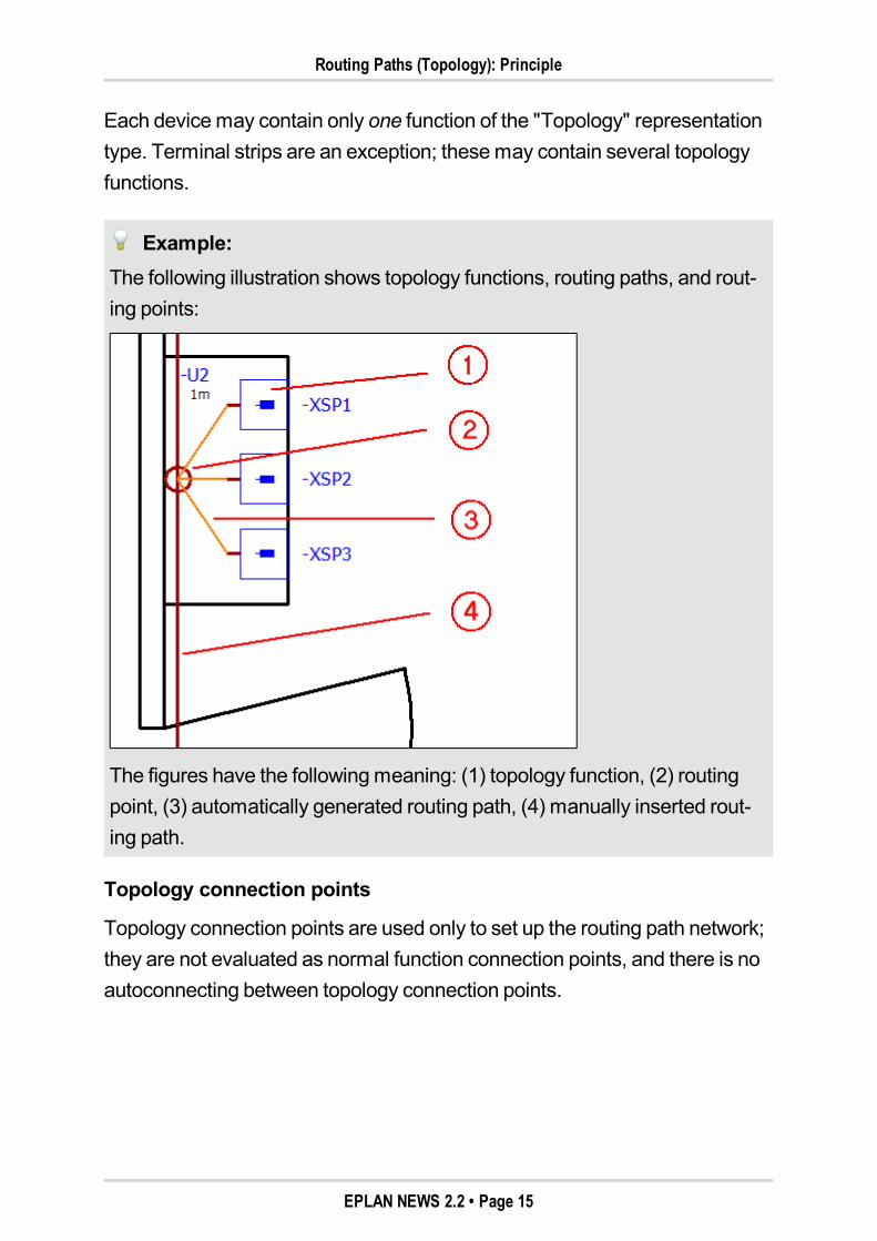
Example:The following illustration shows topology functions, routing paths, and rout-ing points:
The figures have the followingmeaning: (1) topology function, (2) routingpoint, (3) automatically generated routing path, (4) manually inserted rout-ing path.
Topology connection points
Topology connection points are used only to set up the routing path network;they are not evaluated as normal function connection points, and there is noautoconnecting between topology connection points.
EPLAN NEWS 2.2 • Page 15
Routing Paths (Topology): Principle
Usually each topology symbol has only one topology connection point persymbol variant. Even if the symbol has only topology connection points, thetopology function still also has logical function connection points. These func-tion connection points, however, are visible only in the connection point pat-tern of the function.
Topology connection points are connected with routing paths. However, rout-ing connections are connected to the function connection points in the con-nection point pattern of the topology function.
Cable definition lines
If a cable definition line is inserted on a topology page, it will be assigned the"Topology" representation type automatically, as well as the "Topologycable" function definition. Cable definition lines do not have topology con-nection points. No DT adoption occurs for connections intersected by thecable definition line.
Topology interruption points
A routing path can be continued on another project page bymeans of a topol-ogy interruption point. The topology interruption point behaves like any nor-mal interruption point.
Terminal strips
Only terminal strips can bemanaged as topology functions, but not theindividual terminals. The terminals aremanaged via the terminal strip.
A terminal strip with the "Topology" representation typemay occur in severalrouting path networks, but it should occur only once within the same routingpath network.
EPLAN NEWS 2.2 • Page 16
Routing Connections (Topology): Procedure
Routing Connections (Topology): ProcedureRouting is the generation of routing connections with the "Topology" rep-resentation type. The easiest way is to generate the routing connections onthe basis of themulti-line planning. But it is also possible to generate routingconnections on the basis of the topology planning. In addition, you can usethe topology navigator to design routing path networks without graphical rep-resentation. Below, only the routing on the basis of themulti-line planning isdescribed.
Route on the basis of multi-line planningStarting with themulti-line planning, the connections are routed in severalconsecutive steps:
Multi-line planningDefinemulti-line functions, cables, andmulti-line connections through theplanning in the schematic. If you want to route cables in the topology, aclear designationmust be entered for themulti-line cable conductors.
Definition of a routing path networkThis is done by inserting routing points and routing paths on a topologypage. In the process, you can insert routing points and routing paths byusing the newmenu items Insert > Topology > Routing point andInsert > Topology > Routing path. Routing paths are drawn like lines.Routing paths are displayed graphically bymeans of dark-red lines withsnap points at the starting, end and center points.
Placing of topology functionsThis is done by placing functions from the device navigator. Select therequiredmulti-line function, and pull it to a topology page via drag & drop.Alternatively, you can select in the device navigator thePlace > Topol-ogy popupmenu item.
EPLAN NEWS 2.2 • Page 17
Connection point patterns
Routing connectionsThis is done using the newProject data > Topology > Routemenu itemor via theRoute popupmenu item in the new topology navigator. Duringthe route, routing connections are generated and routed in the routingpath network. The routing track and length of the connection are deter-mined automatically for the routing connections. Detailed information onthe length determination can be found in the online help in the section"Determining Connection Length (Topology)".
Tip:If you want to knowwhich cables or connections run through a routing path,select the routing path and select theCables / Connections popupmenuitem. In theCables / Connections dialog that then opens, the connectionsrunning through the routing path are listed. If a complete cable (i.e., all rout-ing connections of the cable) runs through the routing path, the individualconnections are not listed, but instead the DT of the cable is displayed.
Connection point patternsThe connection point patterns of the topology function play a vital role in rout-ing. The data of the connection points that belong to a connection point pat-tern of a topology function are displayed in the property dialog of theConnection point pattern tab.
If there are local connection points, the function connection points of the topol-ogy function are used for routing connections. Otherwise, the connectionpoint data from the part will be taken into account. On the part, the con-nection point data can be defined either in the assigned connection point pat-tern or in the function templates.
EPLAN NEWS 2.2 • Page 18
Topology navigator
If there is no connection point pattern, or there are no connection points, theconnection points will be generated from themulti-line functions during therouting. Detailed information on the connection point pattern can be found inthe online help in the section "Connection Point Patterns (Topology)".
Topology navigatorTo open the new topology navigator, select themenu itemsProject data >Topology > Navigator. Use this dialog tomanage and edit the routing pathnetworks defined in the project.
In the Tree view and List view, the components of the routing path networks –routing paths, routing points, and targets – are displayed with their completeidentifier structure. As targets, only topology functions are displayed, but notthe complete devices. In the List view, you can additionally display other prop-erties that are possible for the routing path networks and devices.
You can use predefined filters to display routing paths, routing points or tar-gets separately.
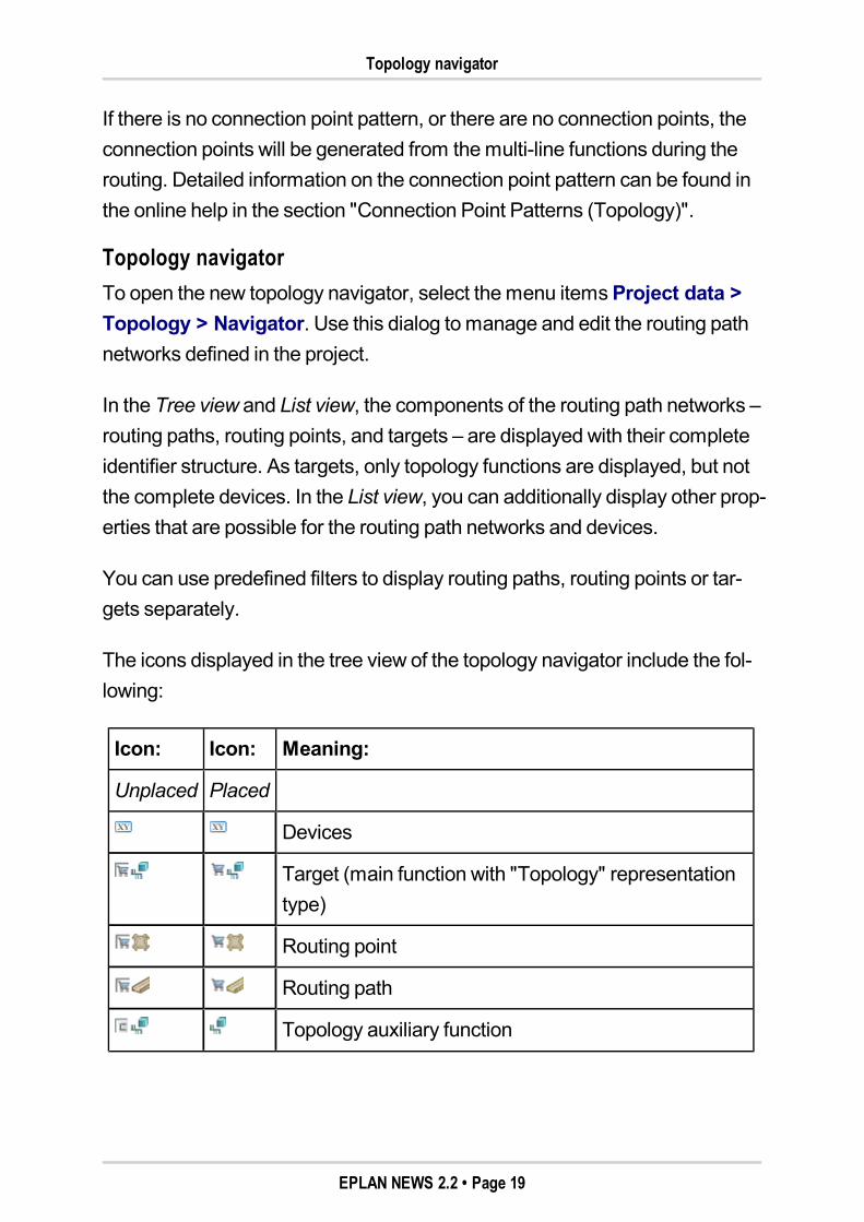
The icons displayed in the tree view of the topology navigator include the fol-lowing:
Icon: Icon: Meaning:
Unplaced Placed
Devices
Target (main function with "Topology" representationtype)
Routing point
Routing path
Topology auxiliary function
EPLAN NEWS 2.2 • Page 19
Insert topology functions
Using appropriatemenu items in the popupmenu, you can generate in thenavigator new, unplaced routing points, routing paths, and targets, and sub-sequently place them on the topology pages.
Insert topology functionsThere are different ways of inserting topology functions:
You can place functions on a topology page from a navigator. In the proc-ess, the function is assigned to a topology function according to its func-tion definition, and this topology function is placed.
You can place topology functions directly on the topology page (using the"Insert symbol" action). But these functions are not yet defined precisely,and youmust assign themulti-line functions to the topology functions at alater point in time (e.g., via the popupmenu item Assign in the devicenavigator).
You can work with devices. Either you generate the devices in the topol-ogy navigator and place them, or you insert the devices directly on thetopology page (using the "Insert device" action). If a macro with the"Topology" representation type is stored for the device, the correspondingtopology functions will be generated from it and placed.
Alternatively, you can also work with unplaced devices in the topologynavigator.
Routing Connections (Topology)Routing connections are connections with the 'Topology' representation type.These connections are generated from themulti-line connections during theroute.
EPLAN NEWS 2.2 • Page 20
Reports
Routing is done in two steps: First, routing connections are generated fromthemulti-line connections (if multi-line connections are highlighted), and thenall the routing connections that exist in the selection are routed in the topol-ogy. For amulti-line connection and /or routing connection to be routed, theremust be topology functions for their sources and targets.
A routing connection has all the properties that amulti-line connection alsohas, but it also additionally contains information about its routing track. If dur-ing a route a connection cannot find a routing track through which it can run, anon-routed routing connection is created. Such a connection graphicallytakes a direct path (i.e., also diagonal) between the source and target, and isrepresented by default as a thin orange line.
Routing connections are copied as well if their targets are highlighted. If bothtargets of a routing connection are deleted, this will also delete the routingconnection.
ReportsThe following reports can be generated on the basis of the routing path net-works and the routed connections:
Topology: Routing path list:Outputs the routing paths with their data androuting points, or the topology functions and their data.
Topology: Routing path diagram:Outputs for each routing path the con-nections and cables that pass through it.
Topology: Routed cables / connections:Outputs all routed cables and con-nections of the project.
In addition, cable reports – following a corresponding adjustment of the forms– can also be supplemented to include information on the routing track (listsof all routing paths that a cable runs through) to support the on-site assemblyteam.
EPLAN NEWS 2.2 • Page 21
Settings for routing connections
Settings for routing connectionsWhen generating routing connections, the project settings are consideredthat are generally defined for routing connections in the layout space and thetopology (menu path:Options > Settings > Projects > "Project name" >Connections > Routing connections). These settings concern the wire ter-mination processing, the connection filter for the generation of routing pathnetworks and the global extra length for the route.
The following special features apply to topology routing connections:
TabWire termination processingThe use of dual sleeves is not evaluated.
TabConnection filterThe settingsmade here are carried over to the Topology: Connectionfilter property (ID 20247) that is available on the routing paths.The connection filter is used during routing to control which connectionsmay be routed through which routing track (routing paths and routingpoints). The values of such criteria can be color assignments of wires orvoltage values. Connection filters are considered only if the Topology:Routing track specification property (ID 31119) is not filled.
TabRouteFor topology routing connections, only the entry in theGlobal extralength field is evaluated. All other settings are not considered.
Function definitions of the connectionsOnly connections with the following function definitions are routed:
Conductor / wire
Connection general
Tube
Pipe
Non-electrical connection
EPLAN NEWS 2.2 • Page 22
Properties of the routing connections
Optical fiber
Process engineering.
Properties of the routing connectionsThe following properties are entered at the connection during routing:
Length (ID 31003)
Connection: Connection point length source (ID 31080)
Connection: Connection point length target (ID 31083)
Topology: Routing track (ID 20237)
Topology: Routing track specification (ID 31119)
Wire termination processing source (ID 31051)
Wire termination processing target (ID 31052)
Connection size source (ID 31096)
Connection size target (ID 31097).
The following properties are additionally entered on cables:
Cable / Conduit: Length (ID 20046)
Cable: Connection point length source (ID 20243)
Cable: Connection point length target (ID 20246)
Topology: Routing track (ID 20237)
Cable / Conduit: Source: Stripping length (ID 20081)
Cable / Conduit: Target: Stripping length (ID 20082).
Routing connections in the connection navigatorIn the tree of the connection navigator, the generated routing connections aredisplayed in the "Topology" representation type in parallel to the existingmulti-line connections. This type of connection is marked in the tree view bythe icon.
EPLAN NEWS 2.2 • Page 23

Changing Route (Topology)
You can use a predefined filter to display only the routing connections for thetopology.
You can also use the connection navigator to route connections. To do so,use theRoute (topology)menu item in the popupmenu of the connectionnavigator.
Using theShow routing connections popupmenu item, you can highlight,for example, selected routing connections in the graphical editor.
Changing Route (Topology)The routing track, determined by the routing, of a routing connection can beinfluenced bymodifying the routing.
Routed connections can be routed from a routing path to another routingpath.
Non-routed connections can be placed on a routing path, so that routingconnections are created from them.
Whenmodifying the routemanually, the Topology: Routing track spec-ification connection property is filled. Subsequently, the connection filtersset for the routing paths are no longer taken into account for the routing ofthese connections.
Tomodify a routing, use the center points of the routing paths and routingconnections. By dragging such a center point to another routing path, the rout-ing track of the connections can bemodified. If several connections runthrough the routing path, a selection dialog is displayed that you can use todecide which of these connections are to bemoved into the new routing path.At the selected connections, the routing paths are then entered in the Topol-ogy: Routing track specification property.
EPLAN NEWS 2.2 • Page 24
Synchronizing Topology Connections and Functions
Synchronizing Topology Connections and FunctionsWhen synchronizing connections displayed in a distributedmanner via themenu itemsUtilities > Synchronize > Connections, the topology functionsare now also taken into consideration under "All representation types".
To apply the properties of routing connections in the topology to the other rep-resentation types of these connections, you can select the new submenuitem Topology --> all representation types.
When synchronizing the data of functions displayed in a distributedmanner,the topology functions are now also taken into consideration (under "All rep-resentation types").
EPLAN NEWS 2.2 • Page 25
New Features of the Entire EPLAN Platform
New Features of the Entire EPLAN Platform
User InterfaceImproved drag & drop in the EPLAN platformThe drag & drop function in the EPLAN platform has been optimized. Amongother things, this has resulted in improved performance for drag & dropactions.
As for drag & drop in the EPLAN platform, you are now shown an additionalinformation text in the status bar as soon as the action is permitted. This way,you can see when the action is possible and which action you are currentlyexecuting in connection with drag & drop (move pages, place function, insertexternal file, etc.).
Place or assign functions via drag & drop
Previously, you had to decide, prior to the drag & drop in the device navigator(or another project data navigator), whether you wanted to place or assignthe function. Now, you can do this while executing the action.
So, if you now decide to assign the function while executing the drag & drop,simply press the [Ctrl] + [Shift] shortcut keys while performing the draggingaction. When you let go of the left mouse button, the function description ofthe highlighted function will hang on the cursor. Move the cursor to a suitablecomponent, and with one click you can apply the data of the function to thecomponent. A function can no longer be assigned directly via drag & drop.
EPLAN NEWS 2.2 • Page 26
Additional information on project name
Additional information on project nameIn the tree view of the page navigator and all other project data navigators,you can now additionally display for the project name the values of theproject properties as additional information.
Benefit:Projects that are difficult to distinguish based on their project names cannow be identified better bymeans of the additionally displayed informationin the navigators.
You can specify the required additional information using the new user-spe-cific settingAdditional info for project name. (Themenu path to the corre-sponding settings dialog is:Options > Settings > User > Display > Userinterface.) From this drop-down list, select which of the following projectproperties are to be displayed as additional information on the project name:
User supplementary field 1 (ID 40001)
None
Commission (ID 10014)
Project description (ID 10011)
Job number (ID 10013)
Supplementary field [1] (ID 10900 1).
To update the view in a navigator, press the [F5] key.
EPLAN NEWS 2.2 • Page 27
More transparent popup menu in page navigator
More transparent popup menu in page navigatorPreviously in the page navigator, the popupmenu item Propertieswas oftenused to open the page properties instead of the required project properties.Tomodify this, the program behavior was changed for this context. As well,some unnecessary popupmenu items were removed.
Changed behavior
Select in the popupmenu of the page navigator themenu item Properties,and it is now the current selection in the navigator that determines whetherthe properties of a page are displayed, as before, or whether the project prop-erties are also displayed. Once you have selected a project, theProjectproperties dialog is opened in this way. In the submenuProject of thepopupmenu, themenu item Properties has been removed accordingly.
This behavior has also been carried over to the other navigators (device navi-gator, terminal strip navigator, etc.). If you have highlighted in a navigator thetree structure level of an opened project, the project properties are nowopened via the popupmenu item Properties (or Properties (global)).
Removal of unnecessary popup menu items
In addition, the following submenu items have been removed from the popupmenu of the page navigator:
Symbol
Plot frame
Outline (extrusion)
Outline (NC data)
Form.
The functions of thesemenu items are not required for regular project plan-ning, and will continue to be available to you in themainmenuUtilities.
EPLAN NEWS 2.2 • Page 28
Display of identifying numbers
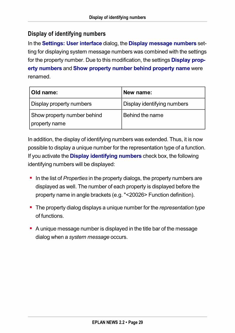
Display of identifying numbersIn theSettings: User interface dialog, theDisplay message numbers set-ting for displaying system message numbers was combined with the settingsfor the property number. Due to this modification, the settingsDisplay prop-erty numbers andShow property number behind property namewererenamed.
Old name: New name:
Display property numbers Display identifying numbers
Show property number behindproperty name
Behind the name
In addition, the display of identifying numbers was extended. Thus, it is nowpossible to display a unique number for the representation type of a function.If you activate theDisplay identifying numbers check box, the followingidentifying numbers will be displayed:
In the list of Properties in the property dialogs, the property numbers aredisplayed as well. The number of each property is displayed before theproperty name in angle brackets (e.g. "<20026> Function definition).
The property dialog displays a unique number for the representation typeof functions.
A uniquemessage number is displayed in the title bar of themessagedialog when a system message occurs.
EPLAN NEWS 2.2 • Page 29
Renamed boxes for structure identifiers
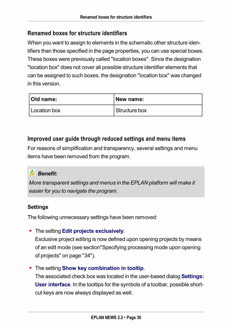
Renamed boxes for structure identifiersWhen you want to assign to elements in the schematic other structure iden-tifiers than those specified in the page properties, you can use special boxes.These boxes were previously called "location boxes". Since the designation"location box" does not cover all possible structure identifier elements thatcan be assigned to such boxes, the designation "location box" was changedin this version.
Old name: New name:
Location box Structure box
Improved user guide through reduced settings and menu itemsFor reasons of simplification and transparency, several settings andmenuitems have been removed from the program.
Benefit:More transparent settings andmenus in the EPLAN platform will make iteasier for you to navigate the program.
Settings
The following unnecessary settings have been removed:
The settingEdit projects exclusively.Exclusive project editing is now defined upon opening projects bymeansof an edit mode (see section"Specifying processingmode upon openingof projects" on page "34").
The settingShow key combination in tooltip.The associated check box was located in the user-based dialogSettings:User interface. In the tooltips for the symbols of a toolbar, possible short-cut keys are now always displayed as well.
EPLAN NEWS 2.2 • Page 30
Improved user guide through reduced settings and menu items
The settingsUse Place identifiers dialog.This user-specific setting of theSettings: Identifiers dialog and the asso-ciatedPlace identifiers dialog have been removed.Using the two existing settings for new structure identifiers, you canmakethe default setting that all newly generated structure identifiers are sortedinto the respective identifier table alphabetically or inserted at the end ofthe respective identifier table. If desired, you can also set another sortingof new structure identifiers in structure identifier management later on.
The filter settings for the data backup of themaster data.During the data backup of master data (basic projects, project templates,symbol libraries, etc.), it is all data that are backed up now. Accordingly,the settings dialogs (underUser > Data backup > Filter) and the Filterfield have been removed from the dialogs used to back upmaster data.
Two settings for the automatic generation of subcables.In theSettings: Cable generation dialog, the two little-used fieldsMax.no. of conductors for subcable andPE conductors included havebeen removed.
The settingSpare as %.In the settings for the automatic cable selection, the associated check boxhas been removed.
The settingExtend symbol connection points.In the two dialogsSettings: Contact image on component andSet-tings: Contact image in path has been reduced by removing theExtend symbol connection points setting. In these dialogs, for the set-tingsDisplay of 1st part number,Display of 1st part type,Display of2nd part number, andDisplay of 2nd part type, the "Above and below"option has additionally been removed.
EPLAN NEWS 2.2 • Page 31
Improved user guide through reduced settings and menu items
The settings for the personal coordinates and increments.For this purpose the settings dialogsSettings: Coordinates andSet-tings: Increments, as well as the corresponding fields in the dialogsCoordinate input andSelect increment have been removed.
The 3D-specific settings for the export of PDF files.In theSettings: PDF export dialog, the 3D tab has been removed forthis purpose.Highlighted 3Dmodels are now always taken into accountduring the PDF export.
Menu items
Other settings are generally specified by the user only once, and thenchanged only rarely or never again. The associatedmenu items have nowbeen removed from the user interface.
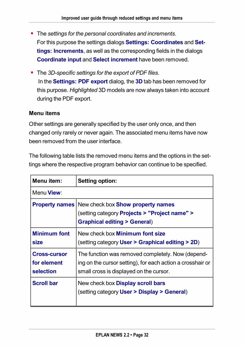
The following table lists the removedmenu items and the options in the set-tings where the respective program behavior can continue to be specified.
Menu item: Setting option:
MenuView:
Property names New check boxShow property names(setting categoryProjects > "Project name" >Graphical editing > General)
Minimum fontsize
New check boxMinimum font size(setting categoryUser > Graphical editing > 2D)
Cross-cursorfor elementselection
The function was removed completely. Now (depend-ing on the cursor setting), for each action a crosshair orsmall cross is displayed on the cursor.
Scroll bar New check boxDisplay scroll bars(setting categoryUser > Display > General)
EPLAN NEWS 2.2 • Page 32
Improved user guide through reduced settings and menu items
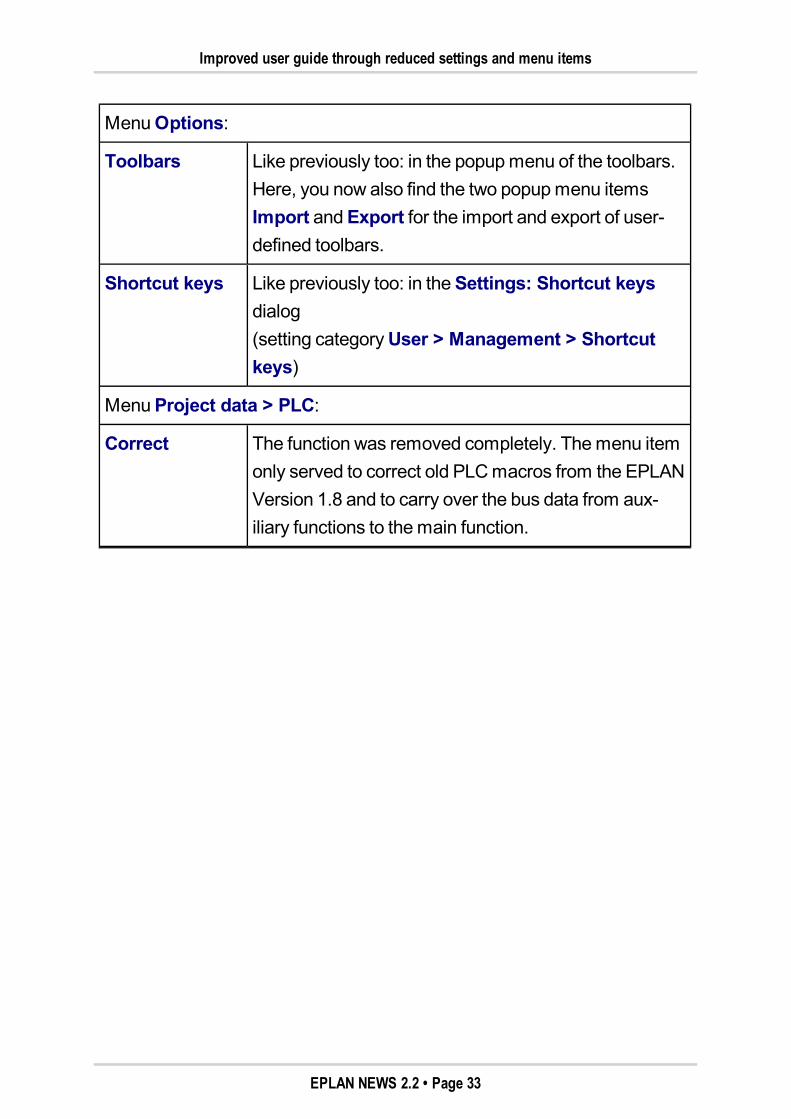
MenuOptions:
Toolbars Like previously too: in the popupmenu of the toolbars.Here, you now also find the two popupmenu itemsImport andExport for the import and export of user-defined toolbars.
Shortcut keys Like previously too: in theSettings: Shortcut keysdialog(setting categoryUser > Management > Shortcutkeys)
MenuProject data > PLC:
Correct The function was removed completely. Themenu itemonly served to correct old PLCmacros from the EPLANVersion 1.8 and to carry over the bus data from aux-iliary functions to themain function.
EPLAN NEWS 2.2 • Page 33
Project Editing
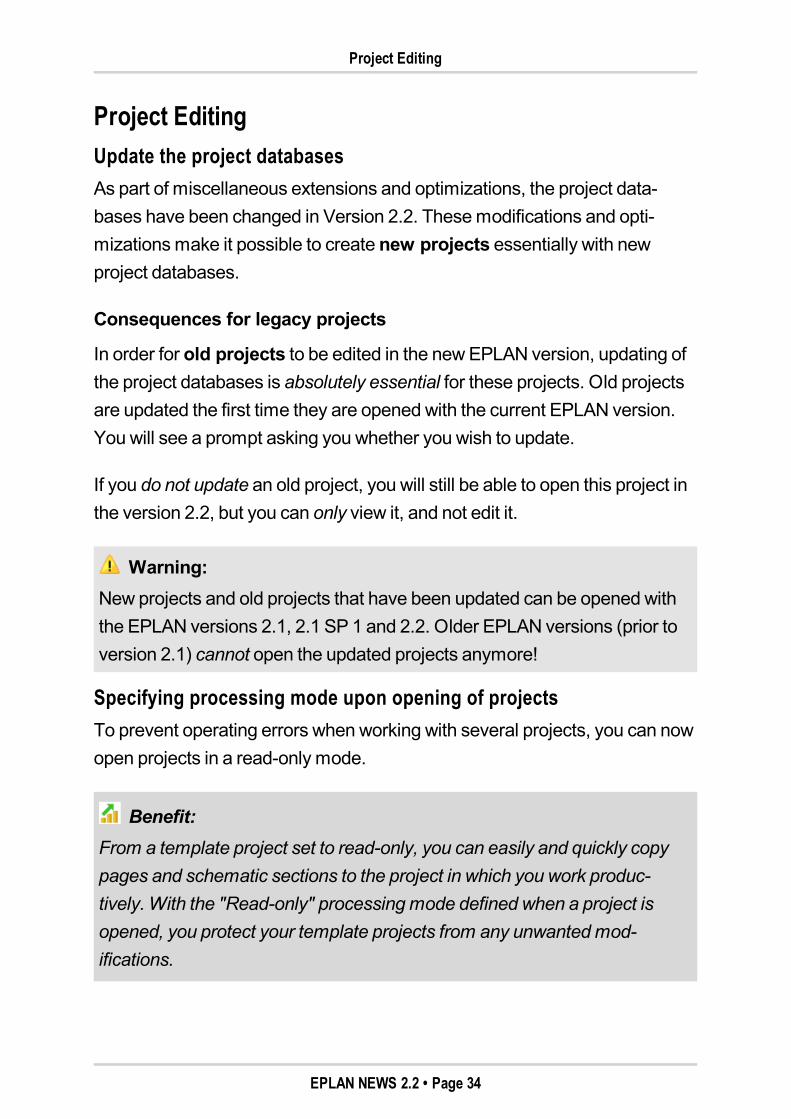
Project EditingUpdate the project databasesAs part of miscellaneous extensions and optimizations, the project data-bases have been changed in Version 2.2. Thesemodifications and opti-mizationsmake it possible to create new projects essentially with newproject databases.
Consequences for legacy projects
In order for old projects to be edited in the newEPLAN version, updating ofthe project databases is absolutely essential for these projects. Old projectsare updated the first time they are opened with the current EPLAN version.You will see a prompt asking you whether you wish to update.
If you do not update an old project, you will still be able to open this project inthe version 2.2, but you can only view it, and not edit it.
Warning:New projects and old projects that have been updated can be opened withthe EPLAN versions 2.1, 2.1 SP 1 and 2.2. Older EPLAN versions (prior toversion 2.1) cannot open the updated projects anymore!
Specifying processing mode upon opening of projectsTo prevent operating errors when working with several projects, you can nowopen projects in a read-only mode.
Benefit:From a template project set to read-only, you can easily and quickly copypages and schematic sections to the project in which you work produc-tively. With the "Read-only" processingmode defined when a project isopened, you protect your template projects from any unwantedmod-ifications.
EPLAN NEWS 2.2 • Page 34
Improved checking and reorganization of projects
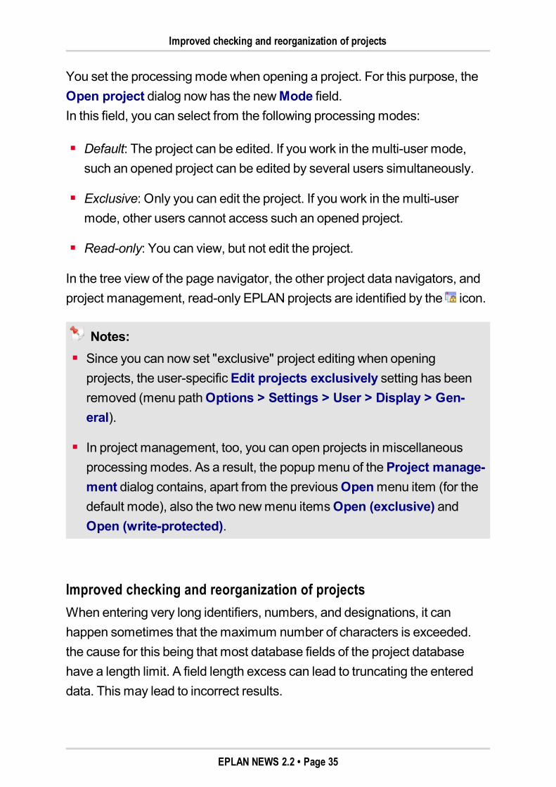
You set the processingmodewhen opening a project. For this purpose, theOpen project dialog now has the newMode field.In this field, you can select from the following processingmodes:
Default: The project can be edited. If you work in themulti-user mode,such an opened project can be edited by several users simultaneously.
Exclusive: Only you can edit the project. If you work in themulti-usermode, other users cannot access such an opened project.
Read-only: You can view, but not edit the project.
In the tree view of the page navigator, the other project data navigators, andproject management, read-only EPLAN projects are identified by the icon.
Notes:Since you can now set "exclusive" project editing when openingprojects, the user-specificEdit projects exclusively setting has beenremoved (menu pathOptions > Settings > User > Display > Gen-eral).
In project management, too, you can open projects in miscellaneousprocessingmodes. As a result, the popupmenu of theProject manage-ment dialog contains, apart from the previousOpenmenu item (for thedefault mode), also the two newmenu itemsOpen (exclusive) andOpen (write-protected).
Improved checking and reorganization of projectsWhen entering very long identifiers, numbers, and designations, it canhappen sometimes that themaximum number of characters is exceeded.the cause for this being that most database fields of the project databasehave a length limit. A field length excess can lead to truncating the entereddata. This may lead to incorrect results.
EPLAN NEWS 2.2 • Page 35
Improved checking and reorganization of projects
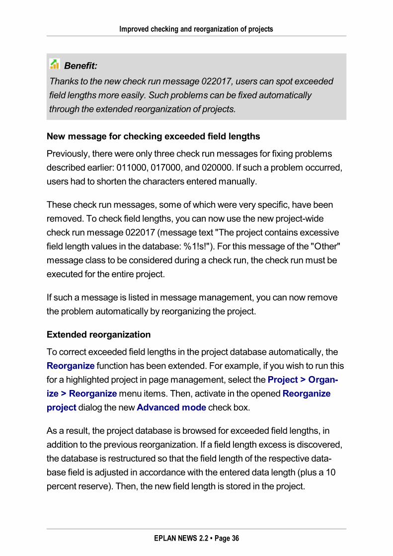
Benefit:Thanks to the new check runmessage 022017, users can spot exceededfield lengthsmore easily. Such problems can be fixed automaticallythrough the extended reorganization of projects.
New message for checking exceeded field lengths
Previously, there were only three check runmessages for fixing problemsdescribed earlier: 011000, 017000, and 020000. If such a problem occurred,users had to shorten the characters enteredmanually.
These check runmessages, some of which were very specific, have beenremoved. To check field lengths, you can now use the new project-widecheck runmessage 022017 (message text "The project contains excessivefield length values in the database: %1!s!"). For this message of the "Other"message class to be considered during a check run, the check runmust beexecuted for the entire project.
If such amessage is listed in messagemanagement, you can now removethe problem automatically by reorganizing the project.
Extended reorganization
To correct exceeded field lengths in the project database automatically, theReorganize function has been extended. For example, if you wish to run thisfor a highlighted project in pagemanagement, select theProject > Organ-ize > Reorganizemenu items. Then, activate in the openedReorganizeproject dialog the newAdvanced mode check box.
As a result, the project database is browsed for exceeded field lengths, inaddition to the previous reorganization. If a field length excess is discovered,the database is restructured so that the field length of the respective data-base field is adjusted in accordance with the entered data length (plus a 10percent reserve). Then, the new field length is stored in the project.
EPLAN NEWS 2.2 • Page 36
Graphical Editor
Graphical EditorUse elements as backgroundElements, such as image files, graphical elements or imported DXF / DWGfiles, can be now used as background images in the graphical editor. For thispurpose, the layer management comes with the newBackground check-box.
Elements located on a layer with the activatedBackground setting cannotbe highlighted and edited. They are always at the very bottom, that is, alsobehind the autoconnecting lines. Concerning the EPLAN705, Graph-
ic.Wallpaper layer, the check box is activated per default.
Benefit:An imported DXF / DWG drawing placed in the background can, thus, bestored in the schematic as additional information. The drawing elements ofthe background are locked and cannot be edited, and do not interfere withthe graphical editing of the schematic. Use the background information assupport during planning – e.g., a machine overview can be used for thelocal positioning of items, or a 2D hall layout as the basis for defining a rout-ing path network using EPLANFieldSys. Even scanned as-built plans can,thus, easily serve as drawing templates.
Set elements as background image
To set an element as a background image, select the Format tab in the prop-erties dialog of the required element. In the Layer field, select a layer forwhich theBackground check box is activated in layer management (e.g.,the EPLAN705, Graphic.Wallpaper layer).
EPLAN NEWS 2.2 • Page 37
Set zoom "100%" with mouse wheel
Edit background image
To edit an element in the background, select in theOptionsmenu the newEdit backgroundmenu item. After editing, select themenu items again inorder to deactivate this option.
Set zoom "100%" with mouse wheelDepending on the set scroll behavior, you can use themouse wheel to zoomin and out in the graphical editor. As with other CAD programs, double-clickthemouse wheel to display the whole page (100% zoom).
New line types for graphical elementsFor the drawing of graphical elements, the Line types field of the propertiesdialog now also displays a number of new line types in addition to the existing7 line types. These new line types weremainly created for the design of P&Idiagrams. For more information on this topic, see chapter "Special TopicsEPLANPPE". Pay special attention to the section "New line types for draw-ing graphical elements" (see page "132").
Using Extended Smart ConnectIt is also possible to cut out symbols or schematic sections on a page andpaste them on another page when smart connect is enabled. In the process,the existing connections aremaintained, and interruption points are insertedautomatically at the autoconnect lines of the highlighted schematic area byEPLAN. Smart connect in this version has been improved and extended. Forfurther information on this topic, see the section "Extended Smart Connect"(see page "73").
EPLAN NEWS 2.2 • Page 38
Use Graphical Macro Selection
Use Graphical Macro SelectionYou can now use a graphical selection dialog for insertingmacros. Users cannow "browse" intuitively in this selection dialog on the basis of stored icons,symbols or other image files through the directory structure and thus find therequiredmacro easily. For further information on this topic, see the section"Graphical Macro Selection" (see page "82").
Find and ReplaceExtended search for placeholder objectsPreviously, it was possible to look for placeholder objects only by the name ofa placeholder object. In the new version of the EPLAN platform, you can nowalso apply the functions Find andReplace to the properties of placeholderobjects (variable, values).
Benefit:With this extension to find and replace, you can nowmodify the variablesand values of placeholder objects quickly.
For this reason, the Find dialog in theSearch in group box has beenextended to include thePlaceholder objects check box. If this check box isactivated, placeholder objects (both in the variables and value sets) aresearched for the search term.
This way, you can find the following properties in placeholder objects and listthem in theSearch results dialog:
Variable on theAssignment tab (property:Assignment: Variable)
Variable, value set name, and values on theValues tab (propertiesValues: Variable, Values: Value set name andValues: Value).
EPLAN NEWS 2.2 • Page 39
Devices
Using theReplace popupmenu item, you can thenmodify the values ofthese properties in theSearch results list and adjust them for the respectiveplaceholder object.
DevicesAssign functions to other device groupsUsually it is the function definition category of a function that decides thedevice group (General devices, Terminal strips, etc.) to which a functionbelongs. Based on the association with a device group (e.g., Generaldevices, Terminal strips, etc.), the different device structures and DT formatsare specified.
In the properties dialog, you can now assign a functionmanually to anotherdevice group. To do so, use the property selection to select the newDevicegroup (ID 20294) property. The following settings are available:
Automatic(With this entry, the device group is determined automatically from thefunction definition.)
General devices
Terminal strips
Plugs
Black boxes
PLC / Bus boxes
Cables
Busbars
General Fluid devices
Fluid distributors
Mechanical devices.
EPLAN NEWS 2.2 • Page 40
Defined Devices
If another device group is assignedmanually, all settings (identifier schemefor the device structure, DT formats for online numbering, etc.) of this devicegroup will be carried over to the function.
Benefit:Since functions can be assigned to other device groups, it is now possible,for example, that connections contain DT formats other than the "Cable"DT format. This way, device tags of fluid power connections (pipes, tubes,etc.) can be numbered with the same device structure as general Fluiddevices.
Defined DevicesNew behavior when generating devices in navigatorsIn this version, the behavior for generating devices in navigators haschanged. Now, by default, themacro entered on the part is no longer takeninto account. A new project setting has been implemented for this:Considermacro when generating devices.
Benefit:Thanks to the new behavior during the generation of defined devices, theuser can control the desired system behavior precisely, and support therequired planning workflow in an optimal manner.
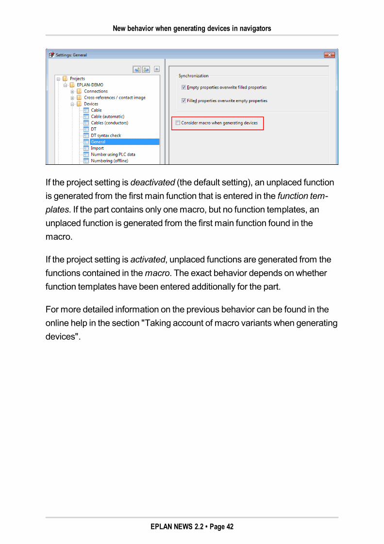
When generating a new device in the navigators (via theNew device popupmenu item), you can choose to use the functions from themacro entered onthe part or from the function templates. This depends on the project settingConsider macro when generating devices (underOptions > Settings >Projects > "Project name" > Devices > General).
EPLAN NEWS 2.2 • Page 41
New behavior when generating devices in navigators
If the project setting is deactivated (the default setting), an unplaced functionis generated from the first main function that is entered in the function tem-plates. If the part contains only onemacro, but no function templates, anunplaced function is generated from the first main function found in themacro.
If the project setting is activated, unplaced functions are generated from thefunctions contained in themacro. The exact behavior depends on whetherfunction templates have been entered additionally for the part.
For more detailed information on the previous behavior can be found in theonline help in the section "Taking account of macro variants when generatingdevices".
EPLAN NEWS 2.2 • Page 42
Project Data Navigators
Project Data NavigatorsQuick input filter in all project data navigatorsNow you can filter the displayed project data in all project data navigators, inthe page navigator, and in the comments navigator via quick input. Pre-viously, this filter option existed only in few navigators (layout space, con-nection navigator, etc.).
Benefit:Thanks to the new flexible quick input, it only takes a click of the button toreduce the project data displayed to the information currently important toyou, and you can concentrate in your planning on what is essential. Thishelps save valuable planning time.
In this context, there is the newValue: <Property> field below the filter in therespective navigator dialogs, both in the tree and list views. You can usequick input in this field to quickly modify the value of a filter criterion for adefined and selected filter.
Displayed operator
For the quick input field, the selected operator (e.g., Value: Mounting loca-tion =) is now additionally displayed behind the property that has been set asthe filter criterion. This makes the logical operation between property, oper-ator, and valuemore transparent for the user.
For further information on the quick input, refer to the online help for the navi-gators.
EPLAN NEWS 2.2 • Page 43
Connections
ConnectionsCarry over connection designations to other connectionsWhen editing connections, you can now carry over automatically to other con-nections the connection designation that was changed in the propertiesdialog. The connection designation can be carried over to all connections ofthe potential, the signal or the net.
Benefit:Since a changed connection designation can be carried over to a wider con-nection extent, you can runmanual corrections on the connection des-ignationsmore quickly.
If you wish to use this new function, youmust first activate the new user-spe-cificCarry over connection designations to extent setting (menu path:Options > Settings > User > Graphical editing > Connection symbols).
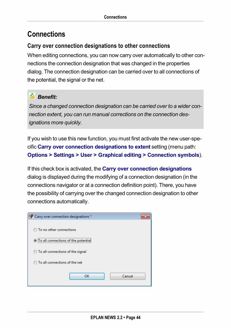
If this check box is activated, theCarry over connection designationsdialog is displayed during themodifying of a connection designation (in theconnections navigator or at a connection definition point). There, you havethe possibility of carrying over the changed connection designation to otherconnections automatically.
EPLAN NEWS 2.2 • Page 44
Determining the next free connection designation
The changed connection designation is then – depending on the optionselected – carried over automatically to all connections within the requiredextent (no transfer, potential, signal, net).
Note:When carrying over connection designations, the filter is taken into accountthat you have defined for the connection numbering. This filter is defined intheSettings: Connection numbering dialog in the Filter tab (accessible,e.g., via themenu pathProject data > Connections > Numbering > Set-tings).
Determining the next free connection designationYou can now determine the next free designation automatically for the con-nection designation of connections and connection definition points.
Benefit:By determining the next free designation, amanually entered connectiondesignation can be adjusted quickly to an existing connection numbering.
For this purpose, the property dialog of connections and connection definitionpoint has been extended to include in theConnection designation field thenewDetermine new designation popupmenu item. Alternatively, you canalso use in this field the [Ctrl] + [N] shortcut keys. On the basis of the settingsfor the connection numbering, the next free connection designation is thendetermined and entered here.
EPLAN NEWS 2.2 • Page 45
Editing in Table
Editing in TableEdit connection data in tableThe properties of connections are now also displayed when editing in tableand can be edited there in a blockwisemanner. The editing of highlightedfunctions and connections is done independently of each other in separatetables.
Benefit:Independent of the graphical placement of the connections, you can edit ina table the properties quickly, as well as in a concentrated and transparentmanner. This way, alsomass data can be edited easily, and extensivemodifications and additions can be worked into the project with minimaleffort.
For editing in table, theEdit function data dialog now includes the two tabsFunctions andConnections. The column configuration of these two tabs isset via a separate scheme.
In theConnections tab, the properties of the highlighted connections are dis-played (e.g., Source, Target,Connection color / number, etc.). This takesinto account all connection definition points that have been placed on the con-nection. If different values have been entered for a property on the con-nection and the associated connection definition points, the value of thegraphically first connection definition point is displayed for which this propertyhas already been filled.
For further information and notes on editing connections in table, see theonline help for theEdit function data dialog.
EPLAN NEWS 2.2 • Page 46
Layer Management
Layer ManagementSet alignment and angle project-wideIn layer management, you can now set the display propertiesAlignment andAngle project-wide for texts and property placements.
Benefit:The alignment and angle of property texts can now be set once project-wide via settings in layer management, and then individually via the respec-tive property dialog. The concentrated project-wide processing optionsaves time, and in an easy way ensures that your documentation has a uni-form and high-quality appearance.
For this purpose, the two columnsAlignment andAngle have been addedto the Layer management dialog. In the drop-down list, you will find thesame setting options as in the property dialog, e.g., on theDisplay tab.
In the property dialog, the two drop-down lists of these display properties(below the Format hierarchy level) now show the entry "From layer" bydefault.
Warning:If schematic elements (e.g. texts) from EPLAN 2.2, for which the value"From layer" is set for theAlignment and / orAngle display properties, areused in an earlier EPLAN version (e.g. via copy & paste or via macro inser-tion), the values from the respective layer cannot be displayed correctly!
EPLAN NEWS 2.2 • Page 47
Reports
ReportsSimplified generation of report projectsIn order to generate a report project while creating a report for anotherproject, you had to execute several steps before and, for example, create acopy of the required schematic project (using theOnly header data option).The present version substantially simplifies the generation of report projects.In themenu pathUtilities > Reports, you will now find the newGeneratereport projectmenu item.
Benefit:The report to a separate project allows for flexible handling in the layout ofdocumentation – especially where extensive projects are involved. Thenew functions simplify the creation of report projects and thus facilitate thereports to a separate project.
For more information on this topic, go to the online help of the EPLAN plat-form and look up the section "Reports from source projects".
To generate a report project, select at first the project in the page navigatorthat you wish to use as the source project. After you have selected themenuitem, theGenerate report project dialog opens. Use this dialog to generatea report project automatically for an existing project. For this purpose, enterthe desired name in the File name field and click [Save].
The header data of the selected project will then be copied and a reportproject without pages is generated. The correct source project is alreadyentered in the report templates of the new report project.
EPLAN NEWS 2.2 • Page 48
Taking into account current page in embedded reports
Note:If there already is a source project in the report templates of the selectedproject, this entry will be retained when generating the report project. Thismay be of interest if a source project is simultaneously a report project (if,e.g., the table of contents of the report project is to be displayed in thesource project).
You can also select an existing project in theReport project dialog. Thisway, an existing report project can be overwritten. After having confirmed thesubsequent prompt for confirmation with [Yes], the "old" report project will bereplaced.
Individual templates as basis for report projects
In the reports, you can now also generate a report project on the basis ofselected report templates.
For this purpose, the newGenerate report projectmenu item has beenadded to the popupmenu of theReports dialog in the Templates tab. Thereport project generated via the subsequentGenerate report project dialogcontains only the templates that were selected in the source project, as wellas the header data of the source project.
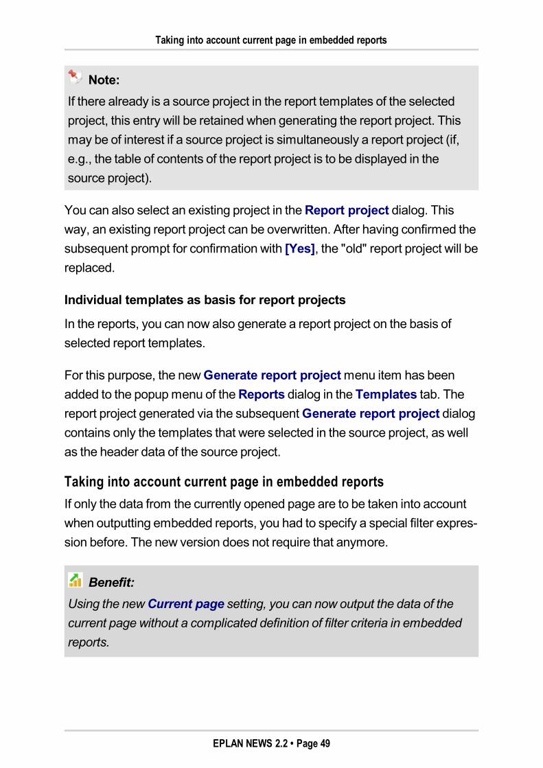
Taking into account current page in embedded reportsIf only the data from the currently opened page are to be taken into accountwhen outputting embedded reports, you had to specify a special filter expres-sion before. The new version does not require that anymore.
Benefit:Using the newCurrent page setting, you can now output the data of thecurrent page without a complicated definition of filter criteria in embeddedreports.
EPLAN NEWS 2.2 • Page 49
Taking into account current page in embedded reports
For this type of report, you can now use, in theSelect report dialog, the newCurrent page setting. Activate the check box to ensure that only the data ofthe current page are taken into account in connection with an embeddedreport.
Note:An embedded report is placedmanually into an open project page. For thispurpose, youmust set the "Manual placement" option in theSelect reportdialog in theOutput format field. Only for this case is theCurrent pagecheck box validated and can be activated.
EPLAN NEWS 2.2 • Page 50
Labeling / External Editing
Labeling / External EditingMicrosoft Office 2007 / 2010 supportIn the new version of the EPLAN platform, both the labeling and external edit-ing were extended in such a way that these functions now also support Micro-soft Office 2007 andMicrosoft Office 2010.
Therefore, you can now select the following Excel formats in the settings forlabeling / external editing besides the existing *.xls file type:
*.xlsx: Format for Microsoft Office 2007 / 2010 without macros
*.xlsm: Format for Microsoft Office 2007 / 2010 with macros
*.xlsb: Binary format for Microsoft Office 2007 / 2010.
The Excel formats listed here are also supported in the import of the exter-nally edited data. In addition, we provide you in the Excel templates suppliedwith several files using the new formats for Microsoft 2007 / 2010.
Note:If you have selected one of the newExcel formats for the target file or for atemplate to be used, but you have a version of Microsoft Office installed onyour computer that does not yet support these formats, the EPLAN plat-form will display a note to this effect. In such a case, you should use the oldExcel format *.xls for Microsoft Excel 97-2003.
EPLAN NEWS 2.2 • Page 51
Automated Processing
Automated ProcessingSynchronize parts data automaticallyIn the automated processing of projects, you can now also complete orupdate the parts data automatically.
In theSettings: Automated processing dialog, you have the following newactions available to you for this purpose:
Update parts in projectUpdates outdated parts data in the project. This will replace outdatedstored parts in the project by newer system parts (i.e. newer parts in theparts database).
Complete parts in projectSearches project for missing parts; if they exist, they will be storedautomatically. Missing parts can occur if parts have first been entered atthemain function in the project and only afterwards have been created inthe parts database.
Complete parts in systemSupplements the system (i.e., the parts database) with parts that arepresent in the project, but not in the system.
In the user interface, you find the corresponding actions under themenu pathUtilities > Parts. These involve themenu itemsUpdate current projectandComplete current project, as well as the twomenu items in theSyn-chronization of parts dialog below the [Extras] button.
EPLAN NEWS 2.2 • Page 52
Parts Management
Parts ManagementUpdate the parts databaseWhen starting the program following an initial installation, the current partsdatabase will be available to you immediately.
If you work with several EPLAN versions (e.g., when switching to version 2.2)and have in version 2.2 an "older" parts database, you will be prompted uponopening parts management to update the parts database. If you answer thisprompt with [Yes], the parts database is updated.
If you click [No], then the parts database is not updated. The parts manage-ment data fields will then remain empty and cannot be edited.
Other program features which also access the data in the parts database willoutput an equivalent message if the parts database does not correspond tothe current version.
Note:If you work with several EPLAN versions, then we recommend using thelatest EPLAN version when editing andmanaging the parts database. Anupdated parts database can be opened in older EPLAN versions, for exam-ple, to select parts or devices, but cannot be edited.
New exchange format for parts managementFor the exchange of records in parts management, you can now use a newdata format. Using the new "EPLANData Portal exchange format", you canfully export one or several parts including associated reference data (drillingpatterns, manufacturers, etc.) and associated additional files (images, mac-ros, PDF documents) and then re-import on another computer.
EPLAN NEWS 2.2 • Page 53
New exchange format for parts management
Benefit:The new exchange format for parts data allows you to exchange completeparts (i.e., with all reference data and additional files, such as images, mac-ros, etc.) with other users. You export and import complete parts data rec-ords at the click of a button, and save yourself the trouble of manualmanagement and assignment of supplementary parts information. Thisfacilitates the extension of your parts database especially in connectionwith the application of new parts data from external sources.
The "EPLANData Portal exchange format" was originally developed for theimport of parts data from the EPLANData Portal to the EPLAN platform.With such an import, the parts and associated additional files (images, doc-uments, etc.) are compressed internally into a zipped file with the file nameextension *.edz.
The extension *.edz stands for EPLANData Archive Zipped. An edz file cancontain one or several parts with reference data and the associated addi-tional files.
Note:Only when you are authorized to use the EPLANData Portal is it possibleto exchange records via the "EPLANData Portal exchange format". If youare successfully logged into the EPLANData Portal, you will see exportand import dialogs in the drop-down list of the File type field with the newexchange format.
EPLAN NEWS 2.2 • Page 54
New exchange format for parts management
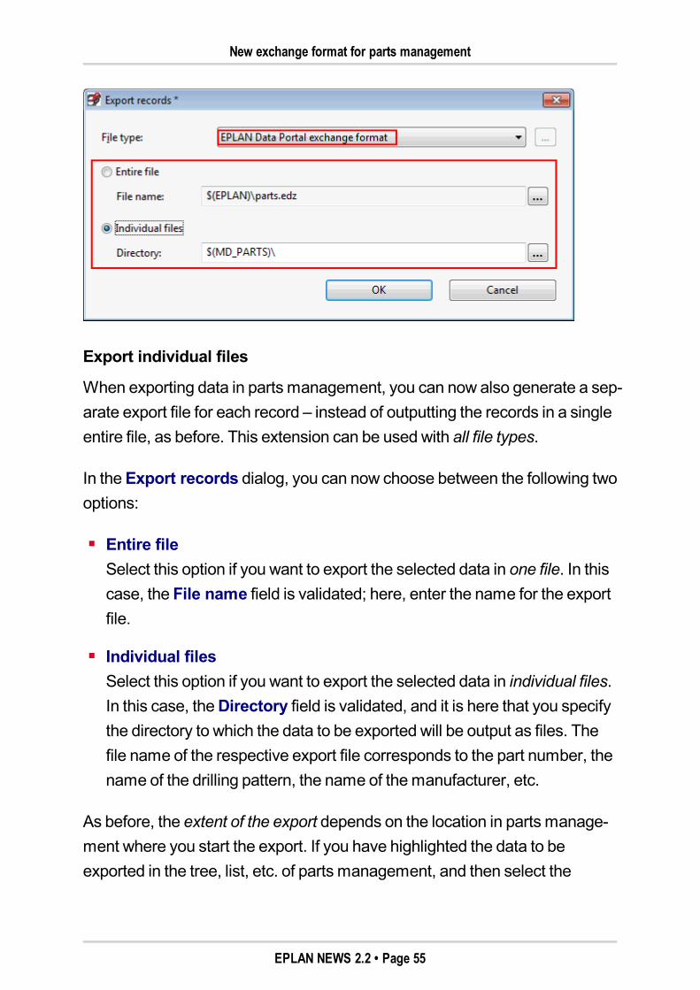
Export individual files
When exporting data in parts management, you can now also generate a sep-arate export file for each record – instead of outputting the records in a singleentire file, as before. This extension can be used with all file types.
In theExport records dialog, you can now choose between the following twooptions:
Entire fileSelect this option if you want to export the selected data in one file. In thiscase, the File name field is validated; here, enter the name for the exportfile.
Individual filesSelect this option if you want to export the selected data in individual files.In this case, theDirectory field is validated, and it is here that you specifythe directory to which the data to be exported will be output as files. Thefile name of the respective export file corresponds to the part number, thename of the drilling pattern, the name of themanufacturer, etc.
As before, the extent of the export depends on the location in parts manage-ment where you start the export. If you have highlighted the data to beexported in the tree, list, etc. of parts management, and then select the
EPLAN NEWS 2.2 • Page 55
New exchange format for parts management
Export popupmenu item, these selected records will be exported as anentire file or individual files. The export of the entire parts database – or sub-sets thereof – occurs when you select theExportmenu item in thePartsmanagement dialog below theExtras button.
New features in the import of records
You can access the new "EPLANData Portal exchange format" also in con-nection with the import of records in parts management. If you are loggedinto EPLANData Portal, the drop-down list File type in the Import recordsdialog also shows such an entry.
You can now enter one or several import files in the File name field. Thisallows for the import of several individual files. For this purpose, in the fileselection for the files to be imported, you canmake amultiple selection offiles in theOpen dialog. This applies to edz files and all other file types.
Use the familiar options for import behavior to specify how existing or newrecords are to be taken into account during the import.
If you have set the "EPLANData Portal exchange format" for the import, therespective record with the reference data (drilling patterns, manufacturers,etc.) and the associated additional files will be carried over to parts manage-ment after selecting an edz file. This will consider the directories specified inthe EPLAN platform, while the additional files (images, macros, etc.) are cop-ied to the specified directories.
If there already are one or several additional files in the respective EPLANdirectory, you will be shown a corresponding confirmation prompt. This is pos-sible, for example, when existing records are updated or when, for example,a PDF has been stored for several parts as a document. If you want to viewall existing additional files one after the other, click [Yes] in the prompt. Click[Yes to all] if you want to overwrite all existing additional files without any fur-ther prompt (e.g., in case of an extensive import).
EPLAN NEWS 2.2 • Page 56
Assigning function templates
Assigning function templatesFor a part in the schematic to be taken into account for the purpose of deviceselection, a set of function templatesmust be stored at the respective part inparts management. In fluid power and process engineering, it has beenimpossible to use a number of parts for device selection due tomissing func-tion templates. When setting up devices, parts were assignedmacros, butthere were no function templates. Thanks to the newAssign function tem-plates function, you can now generate in parts management themissingfunction templates automatically from the storedmacros. For further infor-mation on this topic, see the section "Automatic Assignment of Function Tem-plates for Device Selection" (see page "88").
Extended full-text filterIn the parts management, when you carry out a full-text search within the treeview via the Full-text filter field, it is now also possible to find texts from themain nodes "Accessory list", "Accessory placement", "Drilling pattern", and"Connection point pattern". Entry of the search term is subject to the syntax(+, blank, etc.) familiar to you from Internet search engines.
Note:Please note that the tabs List andCombination display only parts dataand no data from the other main nodes of parts management (Accessorylist, Accessory placement, etc.). Accordingly, a search via the full-text filterin these tabs can locate only parts data.
Menu item "Update search index" moved to parts managementThemenu item Update search indexwasmoved from themenuUtilities >Parts to parts management. In theParts management dialog, you can nowuse themenu item below the [Extras] button.
EPLAN NEWS 2.2 • Page 57
Removed fields
Benefit:The search index for the full-text filter in parts management can now beupdated faster, because it is available directly in parts management.
Removed fieldsIn theMounting data tab, the unnecessaryEMI model field has beenremoved; in the Technical data tab, the outdatedAccessory code field hasbeen removed from the user interface of parts management.
In previous versions, accessory parts were identified by the accessory code.Starting with EPLANVersion 2.0, this is done via theAccessories tab.
Note:The two fieldsEMI model andAccessory code have been removed onlyfrom the user interface of the tabsmentioned. But for reasons of com-patibility, these properties continue to be included in the parts database.
EPLAN NEWS 2.2 • Page 58
New Features in the "EPLAN Revision Management" Extension Module
New Features in the "EPLAN Revision Management" Exten-sion Module
Note:The "EPLANRevisionManagement" extensionmodule is available as anoption for the following program variants:Electric P8 Select, EPLANPPE.This extensionmodule is by default part of the scope of delivery for the fol-lowing program variants:EPLANElectric P8 Professional, EPLANElectric P8 Professional+,EPLANElectric P8 Ultimate, EPLANFluid, EPLANFluid Professional,EPLANPPEProfessional, EPLANPro Panel Professional Stand-alone.
ViaRevision control, the "EPLANRevisionManagement" extensionmodule,modifications of existingmachine and plant documentation can be capturedand documented automatically.
Extended deletion of revisions in change trackingPreviously, revision control only allowed you to remove from a project com-pletely the revisionmarkers and data that were created in a revision project.With themost recent version, you can now use change tracking to delete spe-cific revision information of individual pages or layout space, or to remove thelast revision status of change tracking.
Benefit:With the extensions for deletion, the project revision in EPLAN has beenrendered evenmore flexible. As a result, for example, you can copy pagesof an already revised project to another project, and remove specific,unwanted revision information there.
EPLAN NEWS 2.2 • Page 59
Extended deletion of revisions in change tracking
Delete revision information for the current selection
If you delete revision information in change tracking, the current selection isnow taken into account in the project. TheDelete revision dialog comes withthe familiarApply to entire project check box.
If the check box is deactivated, only the revisionmarkers / revision data of thehighlighted pages or layout spaces will be deleted. Otherwise, the revisioninformation is deleted in the entire project.
Delete latest revision
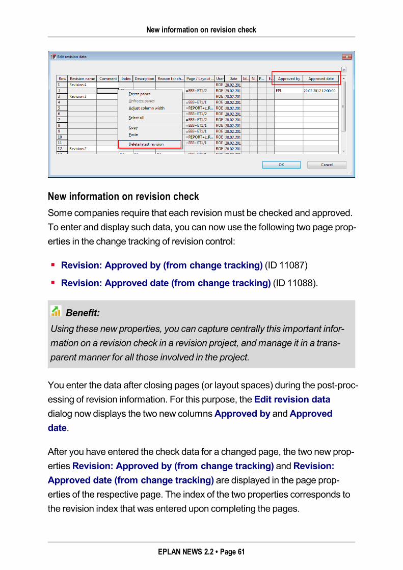
To remove the last revision status during the post-processing of revisions,the popupmenu in theEdit revision data dialog has been extended toinclude theDelete latest revisionmenu item.
This popupmenu item deletes themost recently created revision (i.e., withthemost recent date). In the process, all revision information of such revisionis deleted from the page properties. Modificationsmade on the project pagesand the revisionmarkers remain.
Note:If there are several revisions for a project, they can be removed one by oneusing theDelete latest revision popupmenu item. If there is only onerevision left in the project, it cannot be deleted via this popupmenu itemanymore.
Tip:If necessary, you can remove the revisionmarkers using themenu itemsUtilities > Revision control > Change tracking > Delete revision. How-ever, this will delete all revisionmarkers on the highlighted pages, regard-less of the associated revision.
EPLAN NEWS 2.2 • Page 60
New information on revision check
New information on revision checkSome companies require that each revisionmust be checked and approved.To enter and display such data, you can now use the following two page prop-erties in the change tracking of revision control:
Revision: Approved by (from change tracking) (ID 11087)
Revision: Approved date (from change tracking) (ID 11088).
Benefit:Using these new properties, you can capture centrally this important infor-mation on a revision check in a revision project, andmanage it in a trans-parent manner for all those involved in the project.
You enter the data after closing pages (or layout spaces) during the post-proc-essing of revision information. For this purpose, theEdit revision datadialog now displays the two new columnsApproved by andApproveddate.
After you have entered the check data for a changed page, the two new prop-ertiesRevision: Approved by (from change tracking) andRevision:Approved date (from change tracking) are displayed in the page prop-erties of the respective page. The index of the two properties corresponds tothe revision index that was entered upon completing the pages.
EPLAN NEWS 2.2 • Page 61
New Features in the "EPLAN Multi Language Translation" Extension Module
Output in revision overview
By placing them as placeholder text in a corresponding form, these two pageproperties can also be displayed in a revision overview.
New Features in the "EPLAN Multi Language Translation"Extension Module
Note:The "EPLANMulti Language Translation" extensionmodule is available asan option for the following program variants:EPLANElectric P8 Select.For the following program variants, this extensionmodule is part of thedelivery scope by default:EPLANElectric P8 Professional, EPLANElectric P8 Professional+,EPLANElectric P8 Ultimate, EPLANFluid, EPLANFluid Professional,EPLANPPE, EPLANPPEProfessional, EPLANPro Panel ProfessionalStand-alone.
This version includes extensions also in the Translation utility, the "EPLANMulti Language Translation" extensionmodule.
Translate designations of hyperlinks automaticallyPreviously, in the automatic translation by way of a translation run, the des-ignations of hyperlinks were not considered (menu path:Utilities > Trans-lation > Translate). In the new version, hyperlink designations are now alsoconsidered in the automatic translation.
The translation settings of theExtent tab have been extended so that youcan exclude hyperlink designations from the automatic translation if neces-sary. The newHyperlink Text / designation check box is activated bydefault in this tab. This way, all hyperlinks are translated by default during atranslation run.
EPLAN NEWS 2.2 • Page 62
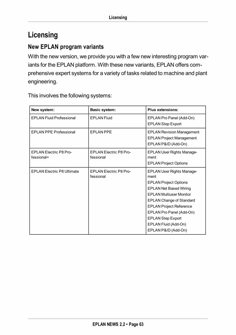
Licensing
LicensingNew EPLAN program variantsWith the new version, we provide you with a few new interesting program var-iants for the EPLAN platform.With these new variants, EPLAN offers com-prehensive expert systems for a variety of tasks related tomachine and plantengineering.
This involves the following systems:
New system: Basic system: Plus extensions:
EPLAN Fluid Professional EPLAN Fluid EPLANPro Panel (Add-On)EPLANStep Export
EPLANPPE Professional EPLANPPE EPLANRevision ManagementEPLANProject ManagementEPLANP&ID (Add-On)
EPLANElectric P8 Pro-fessional+
EPLANElectric P8 Pro-fessional
EPLANUser Rights Manage-mentEPLANProject Options
EPLANElectric P8 Ultimate EPLANElectric P8 Pro-fessional
EPLANUser Rights Manage-mentEPLANProject OptionsEPLANNet BasedWiringEPLANMultiuser MonitorEPLANChange of StandardEPLANProject ReferenceEPLANPro Panel (Add-On)EPLANStep ExportEPLAN Fluid (Add-On)EPLANP&ID (Add-On)
EPLAN NEWS 2.2 • Page 63
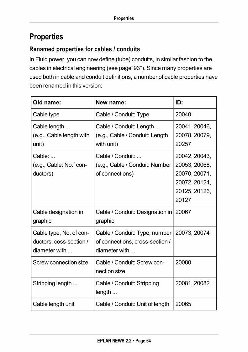
Properties
PropertiesRenamed properties for cables / conduitsIn Fluid power, you can now define (tube) conduits, in similar fashion to thecables in electrical engineering (see page"93"). Sincemany properties areused both in cable and conduit definitions, a number of cable properties havebeen renamed in this version:
Old name: New name: ID:
Cable type Cable / Conduit: Type 20040
Cable length ...(e.g., Cable length withunit)
Cable / Conduit: Length ...(e.g., Cable / Conduit: Lengthwith unit)
20041, 20046,20078, 20079,20257
Cable: ...(e.g., Cable: No.f con-ductors)
Cable / Conduit: ...(e.g., Cable / Conduit: Numberof connections)
20042, 20043,20053, 20068,20070, 20071,20072, 20124,20125, 20126,20127
Cable designation ingraphic
Cable / Conduit: Designation ingraphic
20067
Cable type, No. of con-ductors, coss-section /diameter with ...
Cable / Conduit: Type, numberof connections, cross-section /diameter with ...
20073, 20074
Screw connection size Cable / Conduit: Screw con-nection size
20080
Stripping length ... Cable / Conduit: Strippinglength ...
20081, 20082
Cable length unit Cable / Conduit: Unit of length 20065
EPLAN NEWS 2.2 • Page 64

Special Topics EPLAN Electric P8
Special Topics EPLAN Electric P8
Terminals / PlugsDefinition of switching jumpers and isolating terminalsSwitchable jumpers (switching jumpers) and isolating terminals arefrequently used in energy-supply engineering. In terminal editing in EPLAN, itis now also possible to take into account these components and their switch-ing states in the schematic and to output them in the reports.
Benefit:This possibility of the direct setting of terminals with switching jumpers andisolating terminals improves the effective editing of terminal strips. Theseswitching states can be displayed graphically, if needed, in the terminal dia-gram On the basis of information on the switching states of isolating ter-minals and switching jumpers stored in the project, you can generatemeaningful reports at the click of a button. Thus, your colleagues inmanufacturing and service are also supplied with important informationwithout any substantial additional effort.
Switching jumpers
A switching jumper connects one terminal with the subsequent terminal in aswitchablemanner. Switching jumpers have two switching states ("Open" or"Closed"), and are defined separately for the internal and external sides ofthe terminal. To form switching jumpers, saddle jumper connection pointsare used (where they are free); otherwise, the next free terminal connectionpoints.
To connect terminals bymeans of switching jumpers, the following new prop-erties are now available to you in the property dialog of terminals:
Switching jumper (internal) (ID 20291)
Switching jumper (external) (ID 20292).
EPLAN NEWS 2.2 • Page 65
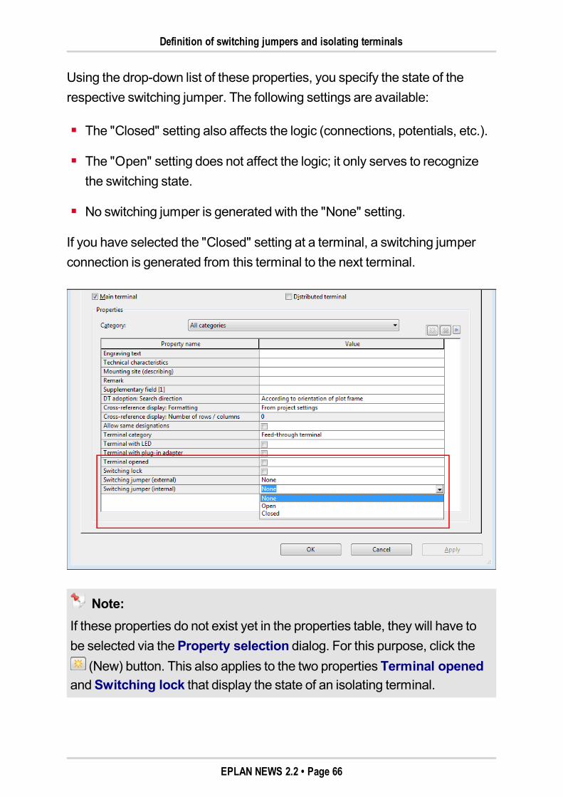
Definition of switching jumpers and isolating terminals
Using the drop-down list of these properties, you specify the state of therespective switching jumper. The following settings are available:
The "Closed" setting also affects the logic (connections, potentials, etc.).
The "Open" setting does not affect the logic; it only serves to recognizethe switching state.
No switching jumper is generated with the "None" setting.
If you have selected the "Closed" setting at a terminal, a switching jumperconnection is generated from this terminal to the next terminal.
Note:If these properties do not exist yet in the properties table, they will have tobe selected via theProperty selection dialog. For this purpose, click the
(New) button. This also applies to the two properties Terminal openedandSwitching lock that display the state of an isolating terminal.
EPLAN NEWS 2.2 • Page 66
Definition of switching jumpers and isolating terminals
Check run message for switching jumpers
Errors in switching jumpers are reported by way of the newmodule-specificcheck runmessage 001032. For example, a switching jumper cannot beclosed if the jumper end does not exist.
Isolating terminals
Isolating terminals connect or separate the external and internal sides of a ter-minal. The state of an isolating terminal can be indicated in the propertydialog of a terminal bymeans of the following two properties:
Switching lock (ID 20293)Using the check box of this new property, you specify whether the ter-minal is locked and cannot be switched.
Terminal opened (ID 20232)You can use the check box for this property to indicate whether the ter-minal is open. This existing property has been extended for the new ver-sion.If the property is activated, the connection between the internal and exter-nal sides of the terminal is separated, i.e., the potential transfer within theterminal is interrupted.
Tip:You can recognize an interruption of the potential transfer of the respectiveterminal if you highlight the potentials in the schematic by color using poten-tial tracking.
Extensions to editing terminal strips
Both the states of switching jumpers and those of isolating terminals can bedisplayed and edited in theEdit terminal strip dialog.
EPLAN NEWS 2.2 • Page 67
Definition of switching jumpers and isolating terminals
For this purpose, in theColumn configuration dialog activate the checkboxes for the propertiesSwitching jumper (internal), Switching jumper(external), Switching lock, and Terminal opened.
Through an appropriatemodification of the drop-down list / check boxes inthe columnsSwitching jumper (internal), Switching jumper (external),Switching lock, and Terminal opened, the state of a switching jumper / iso-lating terminal can be changed. Changed settings are written back to theschematic.
Display of the switching states in the schematic
At the terminals in the schematic, switching states (of switching jumpers andisolating terminals) can be displayed directly via the properties listed aboveor via the block properties.
New features for generating reports of terminals
For the graphical display of switching jumpers in terminal reports, the "Ter-minal" placeholder element was extended to include the following new prop-erties:
Graphic for internal switching jumpers (ID 13094)
Graphic for external switching jumpers (ID 13095).
If you have placed such a placeholder text, for example, in a terminal dia-gram form, a simple display will showwhether terminals are connected toeach other bymeans of a closed or opened jumper.
EPLAN NEWS 2.2 • Page 68
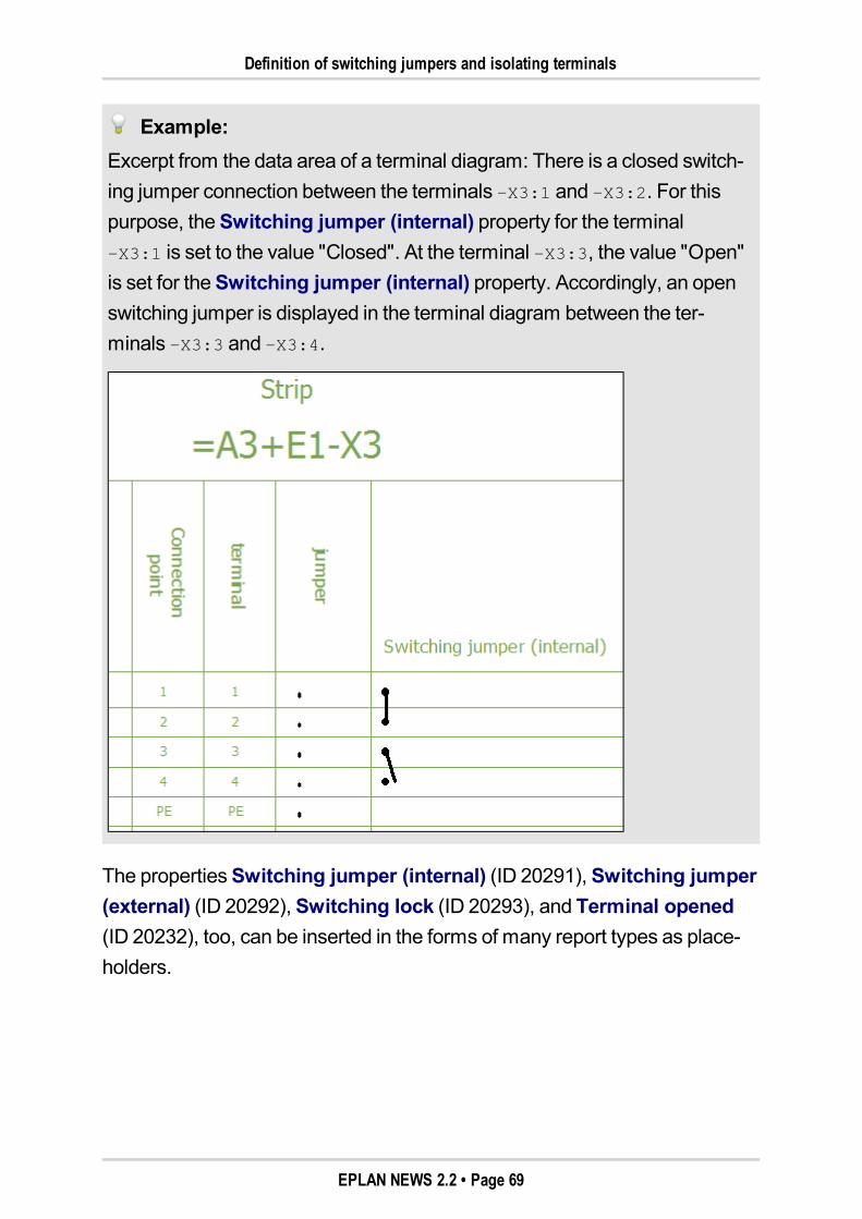
Definition of switching jumpers and isolating terminals
Example:Excerpt from the data area of a terminal diagram: There is a closed switch-ing jumper connection between the terminals –X3:1 and –X3:2. For thispurpose, theSwitching jumper (internal) property for the terminal–X3:1 is set to the value "Closed". At the terminal –X3:3, the value "Open"is set for theSwitching jumper (internal) property. Accordingly, an openswitching jumper is displayed in the terminal diagram between the ter-minals –X3:3 and –X3:4.
The propertiesSwitching jumper (internal) (ID 20291), Switching jumper(external) (ID 20292), Switching lock (ID 20293), and Terminal opened(ID 20232), too, can be inserted in the forms of many report types as place-holders.
EPLAN NEWS 2.2 • Page 69
Distributed terminal index for distributed terminals of the same name
Distributed terminal index for distributed terminals of the same nameDistributed terminals are usually identified clearly via the terminal des-ignation. But if you want to use identical designations for several distributedterminals (e.g., because terminals within a signal are to have the same ter-minal designation), then the distributed terminals must also have the sameterminal designation. In such a case, you can now differentiate distributed ter-minals with the same designation using the new propertyDistributed ter-minal index (ID 20223).
Benefit:The newDistributed terminal index property allows you to identify clearlyterminals within a signal with the same terminal designation.
You can select theDistributed terminal index property in the propertydialog of the terminals via the property selection. The value of this propertycan be enteredmanually, or be assigned automatically during the opti-mization of the distributed terminals. Distributed terminals with the same dis-tributed terminal index are recognized as belonging together.
Extended optimization of distributed terminals
If the distributed terminal index is to be assigned automatically during the opti-mization of distributed terminals, youmust activate theKeep existing ter-minal designations check box in theOptimize distributed terminalsdialog. If this check box is activated, existing terminal designations for dis-tributed terminals are retained. If several terminals have the same terminaldesignation, a distributed terminal index is assigned automatically.
In addition, theOptimize distributed terminals dialog has been extendedto include theKeep existing distributed terminal index check box. By acti-vating this setting, you can specify that manually entered values or valuesassigned during the above optimization are retained for the distributed ter-minal index.
EPLAN NEWS 2.2 • Page 70
New Busbar Definition
New Busbar DefinitionIn analogy to the terminal strip and plug definitions, EPLAN now comes alsowith busbar definitions. This way, parts that belong to the total busbar can beentered at the busbar definition andmanaged. In addition, parts especiallyrequired for the respective connection point can be stored at the individualbusbar connection points.
Open theSymbol selection dialog to insert busbar definitions. In the SPE-CIAL symbol library, select the new symbol with the name BBDEF. You willfind this symbol without symbol graphic in the tree of the symbol selectionunder Electrical engineering > Special function in electrical
engineering > Busbar definition. After inserting it in the schematic,the property dialog is opened with the newBusbar definition tab.
New Features in the "EPLAN PLC & Bus Extension" Exten-sion Module
Note:The "EPLANPLC&Bus Extension" extensionmodule is an optional forEPLANElectric P8 Select. This add-on is part of the standard scope ofdelivery for EPLANElectric P8 Professional, EPLANElectric P8 Pro-fessional+, and for EPLANElectric P8 Ultimate.
The "PLC&Bus Extension" extensionmodule helps you tomanage PLC con-trollers and bus systems.
Take into account plug DT when generating symbolic addressWhen generating the symbolic address of PLC connection points automati-cally, the plug DT of a connected device connection point is now taken into ac-count by default.
EPLAN NEWS 2.2 • Page 71
Updated interfaces for exchanging data with PLC configuration systems
Benefit:By taking into account the plug DT of device connection points, duplicatesymbolic addresses can be avoided.
For this purpose, the Format of symbolic address tab in theSettings:PLC-specific dialog has been extended to include thePlug DT check box.
If this check box is activated, the plug DT of the device connection point ispart of the symbolic address. You have the option of specifying a different pre-ceding sign for the assignment list.
This setting has now been activated by default for all schemes supplied.
Updated interfaces for exchanging data with PLC configuration sys-temsIn this version, several interfaces for the data exchange with PLC con-figuration systems have been updated.
RSLogix Architect
For the PLC data exchange between EPLANElectric P8 and the PLC con-figuration software "RSLogix Architect" from Rockwell, the device family"FLEX I/O" is now also supported. The PLC interface in the EPLAN platformwas extended accordingly.
Beckhoff TwinCAT
The PLC interface for "Beckhoff TwinCAT" was extended in such a way that itcan be used also to design the "EtherCAT" fieldbus systems.
Schneider Unity Pro
This interface allows the exchange of PLC data between EPLANElectric P8and the "Unity Pro" PLC configuration software from Schneider Electric.EPLAN now also supports "Unity Pro" in Version 6.0.
EPLAN NEWS 2.2 • Page 72
Special Topics EPLAN Fluid
Special Topics EPLAN Fluid
Extended Smart ConnectIt is also possible to cut out symbols or schematic sections on a page andpaste them on another page when smart connect is enabled. In the process,the existing connections aremaintained, and interruption points are insertedautomatically at the autoconnect lines of the highlighted schematic area byEPLAN.
Benefit:Using the extended smart connect, you can distribute schematic sectionsfrom confusing schematic pages to several other pages quickly. This way,for example, large-format schematics can be distributed easily to severalsmall-format schematic pages.
For every interrupted connection, EPLAN places on the source page an inter-ruption point and on the target page an interruption point with identical fullDT. The assignment of device tags for automatically generated interruptionpoints occurs independently of themanually inserted interruption points thatalready exist in the project. There are new settings available to you for thisDT assignment of interruption points in connection with smart connect. In theprocess, no interruption point designations are assigned that already exist inthe project.
We discuss the following topics in the next sections:
"Cutting and pasting of schematic elements using smart connect" onpage "74"
"Settings for automatically placed interruption points" on page "76"
"New interruption point symbol for fluid power" on page "78".
EPLAN NEWS 2.2 • Page 73
Cutting and pasting of schematic elements using smart connect
Cutting and pasting of schematic elements using smart connectIf you want to use smart connect when cutting and pasting schematic ele-ments, activate first theSmart connectmenu item in theOptionsmenu.Select the required schematic elements and cut those elements usingEdit >Cut.
Interruption points are immediately inserted on the affected autoconnectlines on the source page. These interruption points are numbered automati-cally according to the settings in theSettings: Smart connect dialog (seesection"Settings for automatically placed interruption points" on page "76").
To insert the schematic elements at any position in the schematic – this canalso be on another page – select theEdit > Pastemenu items. In addition tothe cut schematic elements, the automatically inserted interruption points arealso displayed on the cursor. With a single click, the schematic section isinserted on the target page with the interruption points.
By default, when cutting and pasting, schematic elements are not supposedto be changed. Therefore, for the numbering, select from the subsequentlyopened Insertion mode dialog theDo not modify option. As you know fromcutting and pasting, the section remains on the clipboard and can be pastedseveral times. Only once you cancel the action is pasting terminated.
On the automatically generated interruption points, cross-references to thecounterpieces are displayed on the source page. Press the [F] key in order tojump back and forth between an interruption point and the respective counter-piece.
EPLAN NEWS 2.2 • Page 74
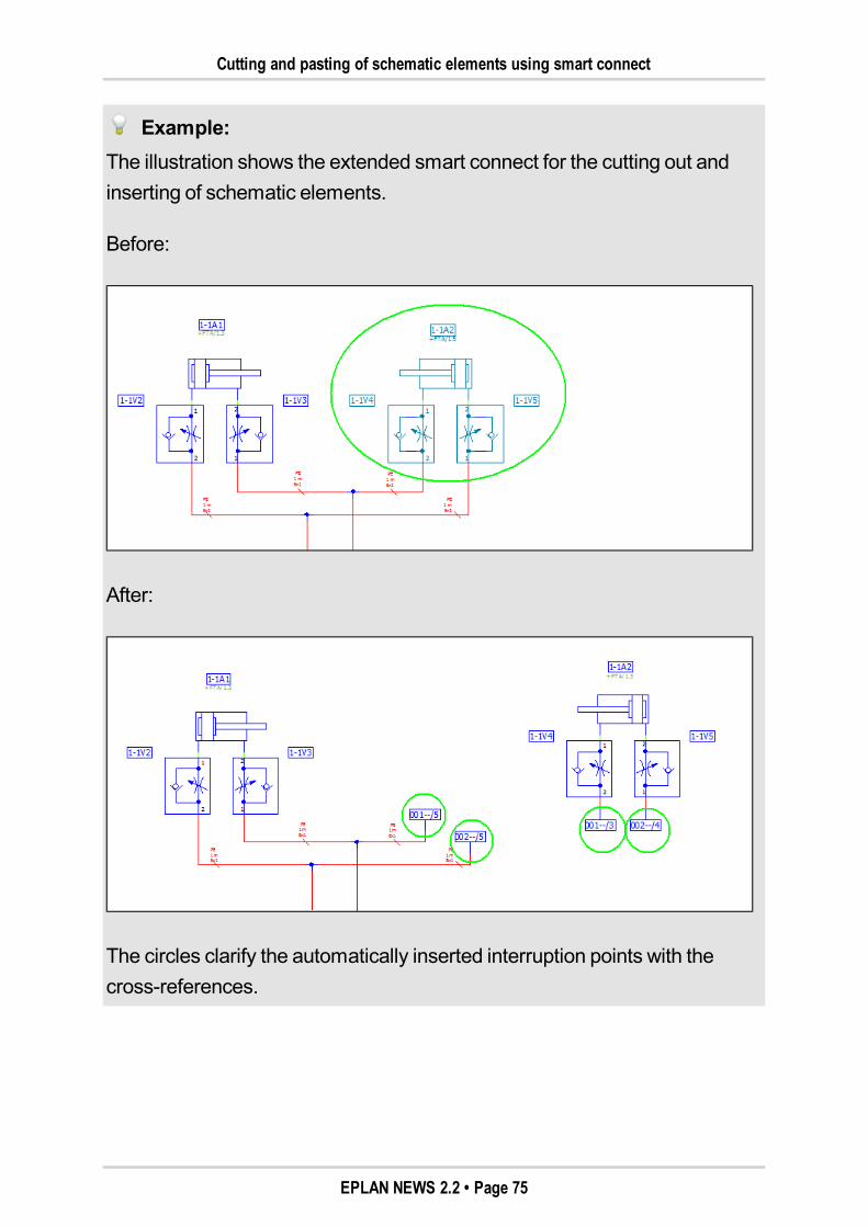
Cutting and pasting of schematic elements using smart connect
Example:The illustration shows the extended smart connect for the cutting out andinserting of schematic elements.
Before:
After:
The circles clarify the automatically inserted interruption points with thecross-references.
EPLAN NEWS 2.2 • Page 75
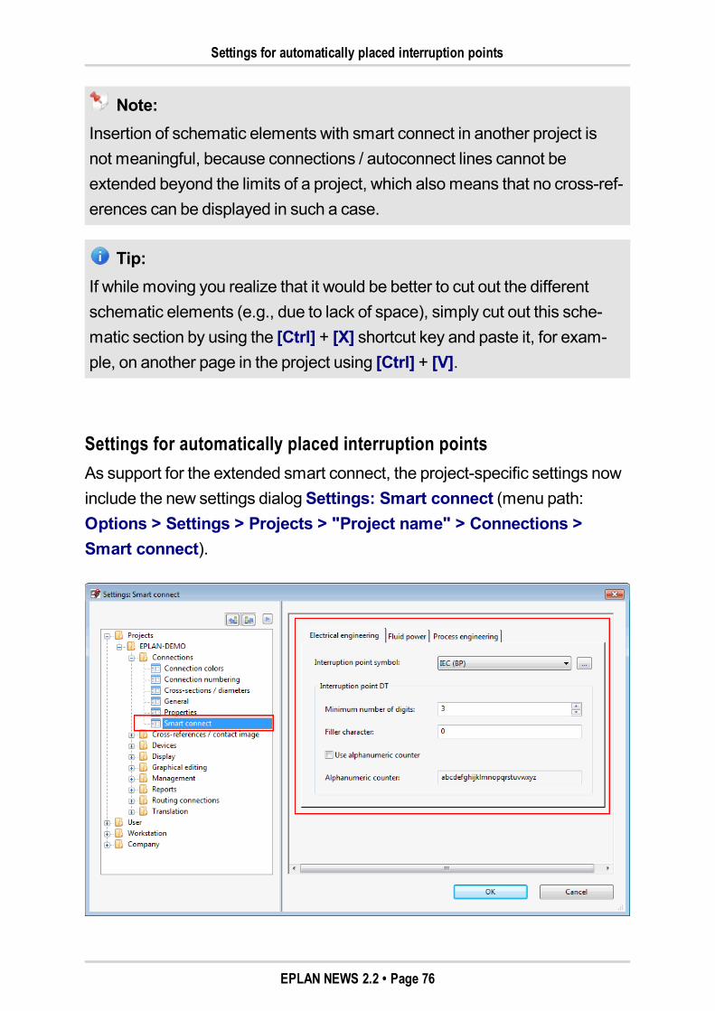
Settings for automatically placed interruption points
Note:Insertion of schematic elements with smart connect in another project isnot meaningful, because connections / autoconnect lines cannot beextended beyond the limits of a project, which alsomeans that no cross-ref-erences can be displayed in such a case.
Tip:If while moving you realize that it would be better to cut out the differentschematic elements (e.g., due to lack of space), simply cut out this sche-matic section by using the [Ctrl] + [X] shortcut key and paste it, for exam-ple, on another page in the project using [Ctrl] + [V].
Settings for automatically placed interruption pointsAs support for the extended smart connect, the project-specific settings nowinclude the new settings dialogSettings: Smart connect (menu path:Options > Settings > Projects > "Project name" > Connections >Smart connect).
EPLAN NEWS 2.2 • Page 76
Settings for automatically placed interruption points
Use this dialog to specify the settings for interruption points that are insertedautomatically when cutting and pasting schematic elements with smart con-nect.
By default, different interruption point symbols are set for the different trades"Electrical engineering", "Fluid power", and "Process engineering". As aresult, depending on the page type of the page on which the cut schematicelements are pasted, different interruption point symbols are used.
Interruption point symbol:Select from this drop-down list a scheme for the interruption point symbol.EPLAN supplies you with different schemes and different interruption pointsfor this purpose.
Click [...] to open theSettings: Interruption points for smart connectdialog to create or edit an interruption point scheme there. For further infor-mation on schemes, refer to the online help for this dialog.
Interruption point DT:Use this group box to specify the settings for assigning the displayed DT atthe interruption points generated automatically by smart connect.
The fields in this group box are identical to the settings used for other formatsettings as well (e.g., for online numbering).
According to the settings, the displayed DT of an interruption point is gen-erated as follows:
As a number (check boxUse alphanumeric counter is deactivated; thisis the default setting)
As an alphanumeric counter (check boxUse alphanumeric counter isactivated).
EPLAN NEWS 2.2 • Page 77
New interruption point symbol for fluid power
Notes:TheDT of the automatically generated interruption points is displayedwith a preceding sign if theSet preceding sign setting is activated forinterruption points (menu path:Options > Settings > Projects >'Project name' > Devices > DT).
The settings in the Interruption point DT group box are also used forthe Find new DT function. This function is available to you in the prop-erty dialog for interruption points in the popupmenu of theDisplayedDT field.
New interruption point symbol for fluid powerTomeet the special requirements of fluid power, the SPECIAL symbol libraryhas been extended to include the new interruption point symbol BPF. Usingthis symbol (symbol number 339), you can insert cross-references in a sche-matic that comply with the DIN ISO DIS 1219 standard.
Such cross-references are displayed by default on schematic pages for fluidpower at the automatically inserted interruption points. These interruptionpoints are created when pasting and cutting schematic elements if theSmartconnect option is enabled.
Displayed data in the cross-reference
Displayed DT of the interruption point
Separator
Identifier for the trade of the page on which the counterpiece of the inter-ruption point is located
Separator
Row number where the counterpiece of the interruption point is located
Separator
Column number where the counterpiece of the interruption point islocated.
EPLAN NEWS 2.2 • Page 78
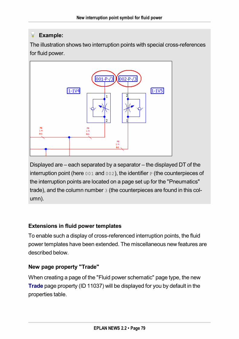
New interruption point symbol for fluid power
Example:The illustration shows two interruption points with special cross-referencesfor fluid power.
Displayed are – each separated by a separator – the displayed DT of theinterruption point (here 001 and 002), the identifier P (the counterpieces ofthe interruption points are located on a page set up for the "Pneumatics"trade), and the column number 3 (the counterpieces are found in this col-umn).
Extensions in fluid power templatesTo enable such a display of cross-referenced interruption points, the fluidpower templates have been extended. Themiscellaneous new features aredescribed below.
New page property "Trade"
When creating a page of the "Fluid power schematic" page type, the newTrade page property (ID 11037) will be displayed for you by default in theproperties table.
EPLAN NEWS 2.2 • Page 79
New interruption point symbol for fluid power
Using this property, you can specify which trade is to be used for a fluidpower page. Via a drop-down list, you can select for a fluid power page one ofthe values: "Fluid power general", "Hydraulics", "Pneumatics", "Cooling", or"Lubrication".
Overall, the following values are possible for the Trade property:
0 = Electrical engineering
2 = Hydraulics
3 = Pneumatics
4 = Cooling
5 = Lubrication
6 = Process engineering
7 = Fluid power, general.
Extended project properties
In addition, the fluid power project templates have also been extended. If youcreate a project on the basis of the current EPLAN project template FL_tpl001.ept or the current EPLAN basic project Fl_bas001.zw9, the fol-lowing two properties will be displayed additionally in the project properties:
Block property: Format (interruption point) [5] (ID 10609 5)
Block property: Replacement text [5] (ID 10660 5).
The first of these project properties specifies the format of the placedBlockproperty [5] property that is used for the cross-reference display at the inter-ruption point symbol BPF.
EPLAN NEWS 2.2 • Page 80
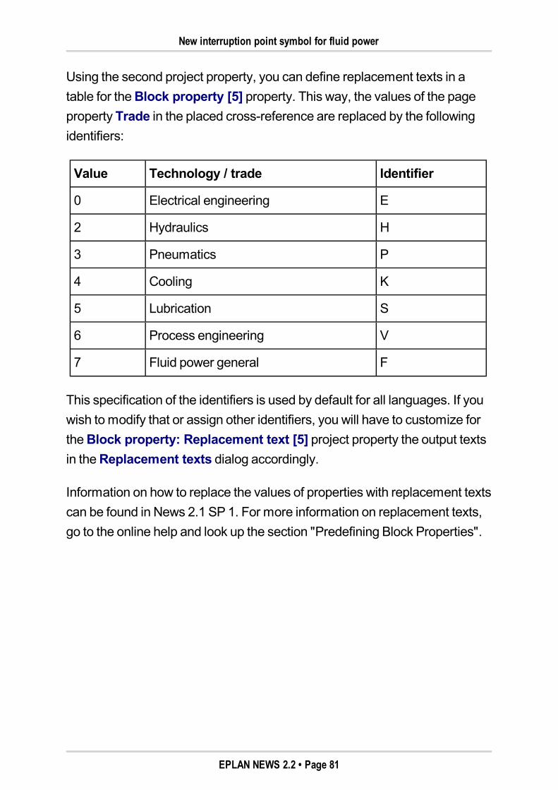
New interruption point symbol for fluid power
Using the second project property, you can define replacement texts in atable for theBlock property [5] property. This way, the values of the pageproperty Trade in the placed cross-reference are replaced by the followingidentifiers:
Value Technology / trade Identifier
0 Electrical engineering E
2 Hydraulics H
3 Pneumatics P
4 Cooling K
5 Lubrication S
6 Process engineering V
7 Fluid power general F
This specification of the identifiers is used by default for all languages. If youwish tomodify that or assign other identifiers, you will have to customize fortheBlock property: Replacement text [5] project property the output textsin theReplacement texts dialog accordingly.
Information on how to replace the values of properties with replacement textscan be found in News 2.1 SP 1. For more information on replacement texts,go to the online help and look up the section "Predefining Block Properties".
EPLAN NEWS 2.2 • Page 81
Graphical Macro Selection
Graphical Macro SelectionYou can now use a graphical selection dialog for insertingmacros. Users cannow "browse" intuitively in this selection dialog on the basis of stored icons,symbols or other image files through the directory structure and thus find therequiredmacro easily.
Benefit:The graphical macro selectionmakes finding and selectingmacros in acomplex directory structure easier. Through a specific configuration in thecompany settings, the graphical macro selection can be adapted directly tothe special features of a company.
The use of the graphical macro selection is shown or hidden via the newuser-specificUse graphical macro selection setting.
We discuss the following topics in the next sections:
"Activating graphical macro selection" on page "83"
"Structure of graphical macro selection" on page "83"
"Specifying image and text for a directory in the selection dialog" onpage "86"
"Managing images and texts for graphical macro selection" on page "86".
EPLAN NEWS 2.2 • Page 82
Activating graphical macro selection
Activating graphical macro selectionIf you want to use the graphical macro selection, youmust activate the newUse graphical macro selection check box in the general user settings forthe display. This setting can be found atOptions > Settings > User > Dis-play > General.
If this check box is activated, the graphical macro selection is used at all posi-tions in the EPLAN platform wheremacros are selected. This is true of the fol-lowing actions:
Insert macro (Insert > Window macro, Insert > Symbol macro, andPage > Insert > Page macro)
Placemacro in project data navigators
Select macro in parts management.
Structure of graphical macro selectionTheGraphical macro selection dialog consists of the following two areas:
AreaDirectory:In this area, all existing subdirectories are displayed as images for aselected directory. By default, an EPLAN logo is used, and the respectivename of the subdirectory is displayed as text.
Area File selection:Here, themacros found in the selected directory are listed by name, type,date, and size in a table format. The preview is integrated in this area.
These two areas (and themacro preview integrated in the file selection) canbe shown and hidden via the appropriate arrow buttons . If a directory doesnot contain anymacros, the File selection area is hidden automatically.
EPLAN NEWS 2.2 • Page 83
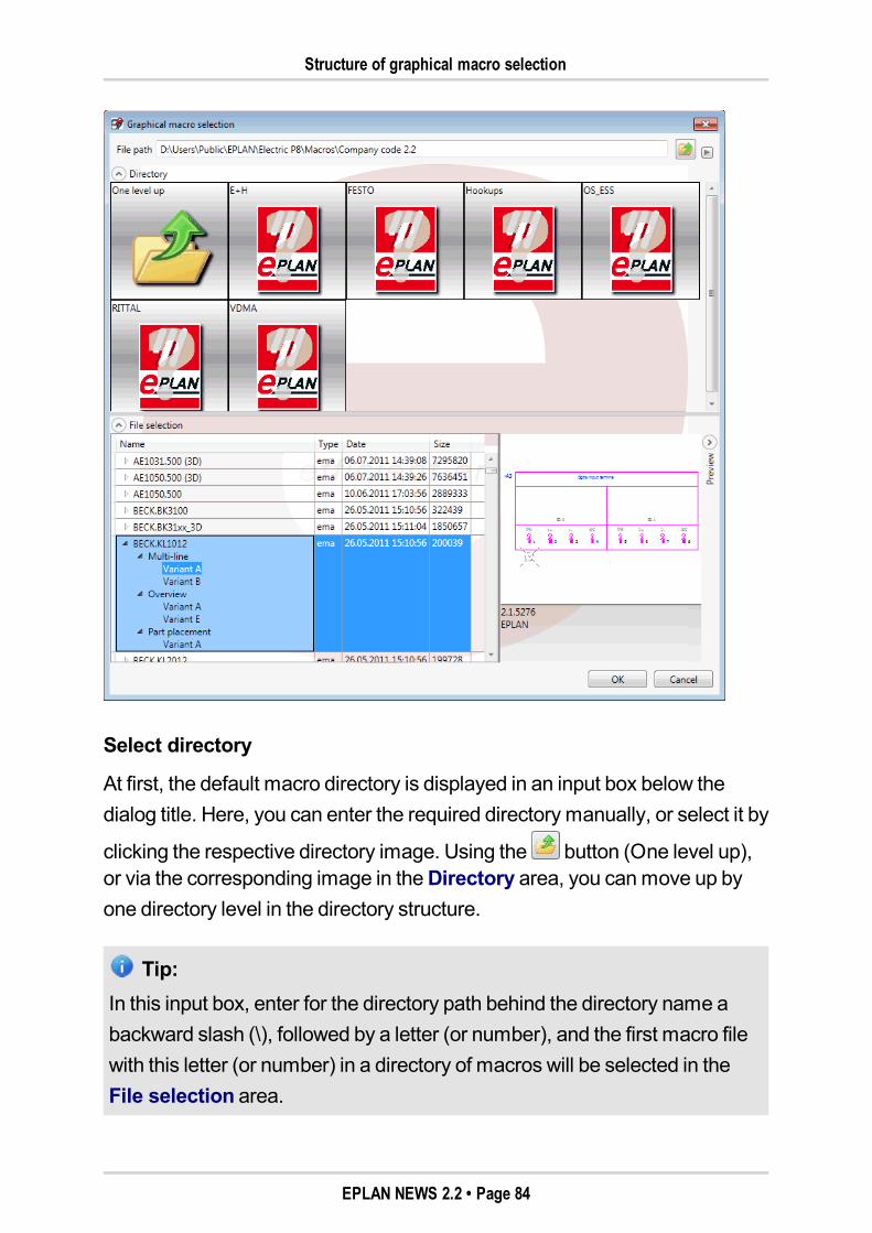
Structure of graphical macro selection
Select directory
At first, the default macro directory is displayed in an input box below thedialog title. Here, you can enter the required directory manually, or select it by
clicking the respective directory image. Using the button (One level up),or via the corresponding image in theDirectory area, you canmove up byone directory level in the directory structure.
Tip:In this input box, enter for the directory path behind the directory name abackward slash (\), followed by a letter (or number), and the first macro filewith this letter (or number) in a directory of macros will be selected in theFile selection area.
EPLAN NEWS 2.2 • Page 84
Structure of graphical macro selection
Using the familiar button on the right margin of the dialog, you can open apopupmenu and select the followingmenu items:
Images: Allows for directory images to be displayed in the image sizes"Small", "Medium" or "Large".
Filter: <File type>: Filters the display of the file selection according to thefile type selected (*.ema, *.ems or *emp, or *.fc2).
Go to default: Restores the selected directory automatically to thedefault macro directory.
Tip:Besides the knownmacro file types, you can also filter the display of the fileselection according to outlines of the "Outline extrusion" type (*.fc2). Thisis relevant to the Technical data tab in parts management. There, you canalso assign to a part an outline drawing via theMacro field. With the selec-tion of such outline drawing, it is also possible to use the graphical macroselection as well.
When calling up the graphical macro selection again, the dialog with themacromost recently selected and themost recent settings is opened again.
Further information on a macro
To find out about the representation type of themacro, and whether there arepossibly several variants, click the button in front of amacro name, and inthe hierarchy levels below, the existing representation types ("Multi-line","Single-line", etc.). Thanks to the listing in table form, you thus get a goodoverview of themacro variants of amacro.
Select macro
To select amacro, click the required variant, followed by [OK]. By double-clicking amacro name, the first availablemacro variant is selected for inser-tion, and the selection dialog is closed.
EPLAN NEWS 2.2 • Page 85
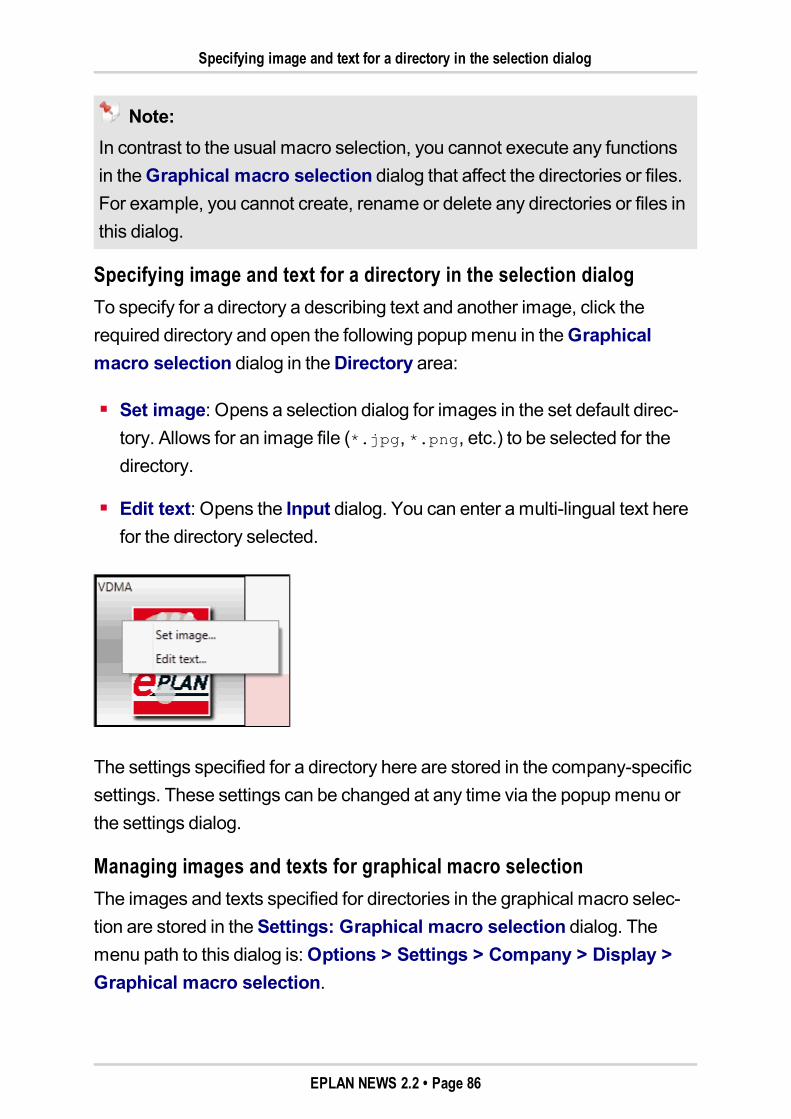
Specifying image and text for a directory in the selection dialog
Note:In contrast to the usual macro selection, you cannot execute any functionsin theGraphical macro selection dialog that affect the directories or files.For example, you cannot create, rename or delete any directories or files inthis dialog.
Specifying image and text for a directory in the selection dialogTo specify for a directory a describing text and another image, click therequired directory and open the following popupmenu in theGraphicalmacro selection dialog in theDirectory area:
Set image: Opens a selection dialog for images in the set default direc-tory. Allows for an image file (*.jpg, *.png, etc.) to be selected for thedirectory.
Edit text: Opens the Input dialog. You can enter amulti-lingual text herefor the directory selected.
The settings specified for a directory here are stored in the company-specificsettings. These settings can be changed at any time via the popupmenu orthe settings dialog.
Managing images and texts for graphical macro selectionThe images and texts specified for directories in the graphical macro selec-tion are stored in theSettings: Graphical macro selection dialog. Themenu path to this dialog is:Options > Settings > Company > Display >Graphical macro selection.
EPLAN NEWS 2.2 • Page 86

Managing images and texts for graphical macro selection
You can also use this settings dialog to specify first the texts and images foryour macro directories before opening the graphical macro selection. Clickthe (New) button, and then adjust the required settings for the new line inthe columnsDirectory, Text, and Image.
Using the [...] button in the columnDirectory or Image, you can navigate toa corresponding selection dialog where you select the required directory /image.
The usual export and import functions for the settings dialogs allow you sharethese settings for directories with other users.
EPLAN NEWS 2.2 • Page 87
Automatic Assignment of Function Templates for Device Selection
Automatic Assignment of Function Templates for DeviceSelectionFor a part in the schematic to be taken into account for the purpose of deviceselection, a set of function templatesmust be stored at the respective part inparts management. In fluid power and process engineering, it has beenimpossible to use a number of parts for device selection due tomissing func-tion templates. When setting up devices, parts were assignedmacros, butthere were no function templates. Thanks to the newAssign function tem-plates function, you can now generate in parts management themissingfunction templates automatically from the storedmacros.
Benefit:Using theAssign function templates function, users can use the deviceselection without major additional efforts throughout all program variants ofthe EPLAN platform.
Assign function templates in parts managementTo assign in parts management the function templates to individual parts,selected product groups, assemblies or modules, you can now use the newmenu item Assign function templates in the popupmenu of the three tabsTree, List, andCombination. In this, the function affects the area or theparts that have been highlighted in the respective tab.
EPLAN NEWS 2.2 • Page 88
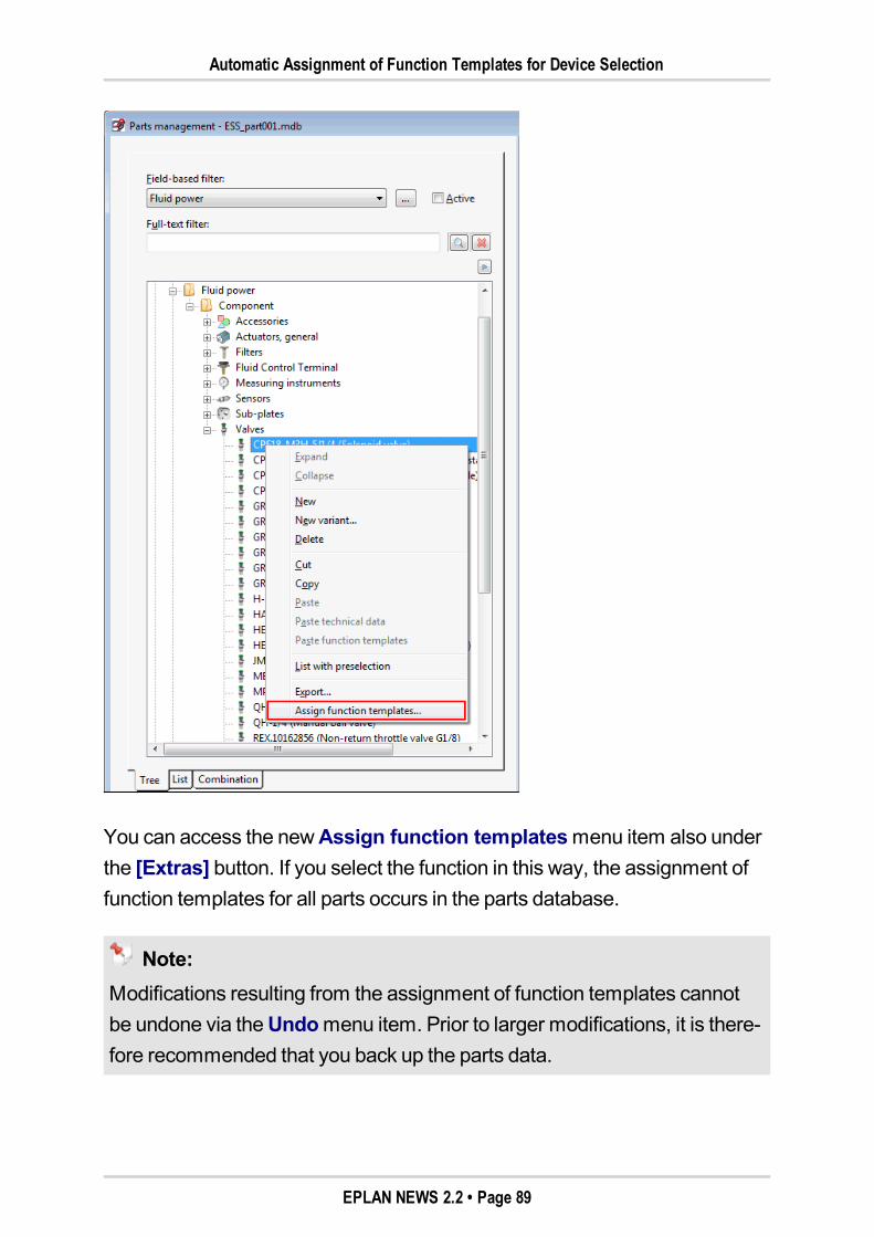
Automatic Assignment of Function Templates for Device Selection
You can access the newAssign function templatesmenu item also underthe [Extras] button. If you select the function in this way, the assignment offunction templates for all parts occurs in the parts database.
Note:Modifications resulting from the assignment of function templates cannotbe undone via theUndomenu item. Prior to larger modifications, it is there-fore recommended that you back up the parts data.
EPLAN NEWS 2.2 • Page 89
Automatic Assignment of Function Templates for Device Selection
After you have selected themenu item, you will be shown at first a con-firmation prompt. Answer the prompt with [Yes], and all selected parts areassigned new function templates. If you click [No], the assignment takesplace only for the selected parts on which no function templates have beenstored yet.
Transfer of data to function templatesIf theAssign function templates function is executed, the program firstchecks whether for the respective part a macro has been entered in the Tech-nical data tab in theMacro field. Then, themacro is browsed for functions. Asuccessful assignment requires that themacromust contain amain function.
The functions found – starting with themain function – are carried over to theFunction templates tab. In the process, all properties on a template arefilled with the data of the function where possible.
If in thePart selection group box of the Function templates tab no datahave been entered for the propertiesConnection point designation, Tech-nical characteristics, Symbol library, andSymbol number, these dataare imported from the first assigned template. If these fields contain differentdata compared to the first function template, no function templates will beassigned.
Note:Parts stored on themain function in themacro are not considered forthe assignment of the function templates.
It is not required that the respectivemacros be placed in the schematic(e.g., as a device) before theAssign function templates function isrun.If themacros have already been inserted in the schematic withoutstored function templates, the function templates will not be overlaid atthe device. After you have assigned the function templates for the
EPLAN NEWS 2.2 • Page 90
Automatic Assignment of Function Templates for Device Selection
respective part in parts management, you will then have to do a syn-chronization of parts with the project. Subsequently, the function tem-plates at the device will be overlaid with those of the part.
Log file in case of incorrect assignment
If an error occurs in the assignment of function templates, a log file will becreated in the specified parts directory. The file name of this log file will bestructured as follows:LOG_<Name of parts database>_<Date and time>.txt.
Possible sources of errors are, for example, amissingmacro on the Tech-nical data tab, or amacro that contains no or several main functions.
EPLAN NEWS 2.2 • Page 91
Fluid Connections
Fluid ConnectionsNew layers for representing connectionsInternal connections for reservoir lines for heating, cooling, and processmedia can now be stored in EPLANFluid on separate layers.
Benefit:With the new lines, the different line types of fluid power in the schematiccan be differentiated from each other even better now.
For this purpose, the new version comes with the following new layers:
EPLAN527, Symbol graphic.Connection sym-
bols.Autoconnecting.Reservoir line internal
EPLAN528, Symbol graphic.Connection sym-
bols.Autoconnecting.Heating and cooling medium internal
EPLAN529, Symbol graphic.Connection sym-
bols.Autoconnecting.Process medium internal.
The properties specified in layer management for these layers determinehow the connections are displayed. By default, these layers have similar set-tings to the layer for internal connections, EPLAN510, Symbol graph-
ic.Connection symbols.Autoconnecting.Internal connections /
direct connections.
In addition, the pattern length of the layer EPLAN524, Symbol graph-
ic.Connection symbols.Autoconnecting.Drain line internal hasbeen changed from "4.00mm" to "2.00mm".
EPLAN NEWS 2.2 • Page 92
Diameter character in connection definition points
Diameter character in connection definition pointsIn the property dialog of a connection definition point, the popupmenu of theCross-section / diameter field now comes with theSpecial characterspopupmenu item. TheSpecial characters dialog then opens. Use thisdialog to place the diameter character – as required under the DIN ISO 1219-2 standard – in front of themeasurements of a fluid power line in the sche-matic.
Note:Please note that some special characters are not available for all fonts. Ifyou want to use these special characters, youmust select suitable fontsfrom theSettings: Fonts dialog.
Definition of ConduitsTo define fluid power connections, you can now use the new "Conduit def-inition" function definition. This function definition is used in the sameway astheCable definition, and is also inserted via the samemenu items. It alsoallows you to assign device tags for pipes, tubes, and conduits. The pipes,tubes, and conduits thus defined as devices are also displayed in the devicenavigator accordingly. This way, a connection can be reported as a deviceand as a connection.
Benefit:Using the new conduit definition, you can now define several parallel con-nections as conduits. In addition, this extension allows you to assign thedevice tags of fluid power connections (pipes, tubes, etc.) in accordancewith the DIN standard 1219-2.
A number of cable properties have been renamed as part of this extension.For more information, please read the section "Properties" (see page "64").
EPLAN NEWS 2.2 • Page 93
Inserting conduit definitions
Inserting conduit definitionsTo insert a conduit definition, select themenu items Insert > Cable def-inition. Whether you insert a cable or conduit definition depends on the pagetype of the selected page in the newEPLAN version. A conduit definition isplaced on a fluid power schematic page.
Depending on what it is you intend to do, you can select from two symbols forthe conduit definition. In this context, the SPECIAL symbol library provides thetwo new special symbols PD and PDL. To open theSymbol selection dialog,press the [Back] key after selecting themenu items.
Define conduitIf you want to define a conduit, select the PDL symbol with the Conduitdefinition line symbol description. As in the case of a cable def-inition, click with the left mouse button to establish the start and end pointof the conduit definition line. Drag the line over the connections to beincluded in the conduit.
Define pipe or tube as deviceIf you want to assign a device tag to a tube or pipe, select the PD symbolwith the Conduit definition, two-sided symbol description. Thesymbol hangs on the cursor and can be placed on the required con-nection.
Automatically placed connection definition pointsAs with cable definitions, when you insert a conduit definition, a connectiondefinition point is placed automatically. In the case of a conduit definition line,a connection definition point is placed on each intersection of the line with aconnection.
On such a connection definition point, the newConduit connection (ID31086) property is activated. The function definition of a connection createdby the conduit definition is set to the "Tube" function definition automatically.
EPLAN NEWS 2.2 • Page 94
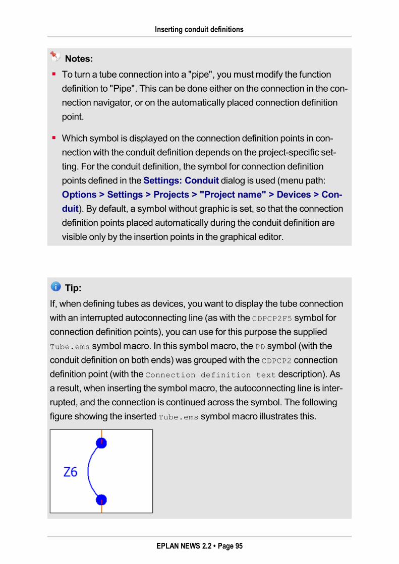
Inserting conduit definitions
Notes:To turn a tube connection into a "pipe", youmust modify the functiondefinition to "Pipe". This can be done either on the connection in the con-nection navigator, or on the automatically placed connection definitionpoint.
Which symbol is displayed on the connection definition points in con-nection with the conduit definition depends on the project-specific set-ting. For the conduit definition, the symbol for connection definitionpoints defined in theSettings: Conduit dialog is used (menu path:Options > Settings > Projects > "Project name" > Devices > Con-duit). By default, a symbol without graphic is set, so that the connectiondefinition points placed automatically during the conduit definition arevisible only by the insertion points in the graphical editor.
Tip:If, when defining tubes as devices, you want to display the tube connectionwith an interrupted autoconnecting line (as with the CDPCP2F5 symbol forconnection definition points), you can use for this purpose the suppliedTube.ems symbol macro. In this symbol macro, the PD symbol (with theconduit definition on both ends) was grouped with the CDPCP2 connectiondefinition point (with the Connection definition text description). Asa result, when inserting the symbol macro, the autoconnecting line is inter-rupted, and the connection is continued across the symbol. The followingfigure showing the inserted Tube.ems symbol macro illustrates this.
EPLAN NEWS 2.2 • Page 95
Display and reports of conduits
Set conduit propertiesAfter placing the conduit definition on the page, theProperties (com-ponents): Conduit dialog opens. Using the newConduit tab, you specifythe properties of the respective fluid power function.
A device tag is entered in theDisplayed DT field automatically. For the "Con-duit definition" function definition to be sorted in the "Fluid power" trade, theDT is numbered automatically with the DT format for Fluid devices.
The values in the fieldsDisplayed DT, Length,Cross-section / diameter,andUnit are carried over from a defined conduit to the connection if the corre-sponding fields in the properties dialog of the automatically placed con-nection definition point have no entry.
Display and reports of conduitsDisplay in the navigatorsThe defined conduits are displayed in the device navigator, but not in thecable navigator. Accordingly, the functions under themenu pathProjectdata > Devices can be executed also for the conduits (Cross-referenceDTs,Number, etc.).
The tree of the device navigator displays the relevant conduit definitions andtubes / pipes below the conduit DT. The icons used for conduit definitions(placed / unplaced) are identical to the icons for cable definitions (e.g., ).
To display in the device navigator only devices that were created by the con-duit definition, use the "Conduit definition" function definition as a filter crite-rion. If you want to display in the connection navigator only the connectionsgenerated by the conduit definition, use theConduit connection (ID 31086)property as a filter criterion.
EPLAN NEWS 2.2 • Page 96

Display and reports of conduits
ReportsThe conduit definitions are not output in the cable reports. To output definedtube conduits, you can use reports of the types "Parts list", "Summarizedparts list", "Device tag list", and "Connection list".
For the output of piping / tubing lists, you can already use, by default, thefilters "Pipes" and "Tube". If you want to output in a connection list only theconnections that were created by a conduit definition, use theConduit con-nection (ID 31086) property as a filter criterion.
EPLAN NEWS 2.2 • Page 97

Special Topics EPLAN Pro Panel
Special Topics EPLAN Pro Panel
EPLANPro Panel stands for customized enclosure engineering and enclo-sure construction in automation technology. Electrical engineering planning,3Dmounting layout, manufacturing, andmountingmerge, through a uniformdata basis, to form a fully integrated solution.
With this version, we introduce our new extensionmodule for the design ofbusbars. The other new features concerning EPLANPro Panel are describedin a separate section (see page "112").
Switchgear Construction – EPLAN Pro Panel Copper forthe Construction of Busbars
Note:The "EPLANPro Panel Copper" extensionmodule is available as anoption for EPLANPro Panel Professional. It does not matter whetherEPLANPro Panel Professional is installed as a stand-alone variant or asan add-on for EPLANElectric P8.
For effective switchgear design, bending and drilling information of copperrails is a key factor. With the newEPLANPro Panel Copper extensionmod-ule for EPLANPro Panel Professional, individual copper rails and connectionelements can be designed freely for switchgear construction, or configuredeasily on the basis of busbar systems technology of different manufacturers(e.g., Rittal).
An ideal addition to the creation of type-tested or design-certifiedmountinglayouts for busbar systems is the planning software "Rittal Power Engi-neering". Rittal Power Engineering allows the type-tested layout of a busbarsystem, and thus specifies also the defaults for the implementation of themounting layout in EPLANPro Panel Copper, and provides such defaults inthe form of bills of materials and 2Dmounting diagrams.
EPLAN NEWS 2.2 • Page 98
Switchgear Construction – EPLAN Pro Panel Copper for the Construction of Busbars
For more information, visit the website of Rittal (e.g.,http://www.rittal.com/de-de/content/de/support/software/projektieren/power_engineering/Power_Engineering.jsp).
The complete 3Dmounting layout is visualized and checked for plausibility.The data obtained on the basis of a virtual prototype can be transferred to NCmachines subsequently for themanufacturing of copper items.
Benefit:Using the new "EPLANPro Panel Copper" extensionmodule, you can con-struct freely individual copper rails and connection elements. The neces-sary expertise about materials, manufacturing techniques or manufactur-ingmachines can be stored in EPLAN, and can be utilized as part ofspecial planning assistance and to verify the construction. Potential dis-turbances are identified early on in the 3D prototype – this accelerates theprocess of switchgear construction and allows for project resources to bescaled.
These innovations provide you with the following possibilities:
The shape and form of copper items can be defined individually andadjusted for the circumstances in the enclosure.
Length and angle changes and associatedmoving of bending positionscan be effected directly on the item bymoving the cursor, without anydetours via parameter dialogs. This allows for actual designing in themounting environment.
Themanufacturing data of the individually constructed copper items areprovided via special machine interfaces and transferred to cutting, bend-ing, milling, punching, or also drillingmachines.
Standardized copper items that are to be purchased in a fixed preset formare assigned thePrefabricated property. This makes it possible to con-trol that the copper items cannot bemodified after the placement.
EPLAN NEWS 2.2 • Page 99
Enclosure engineering with copper items: operation
Wediscuss the following topics in the next sections:
"Enclosure engineering with copper items: operation" on page "100"
"Form for bent copper rails: principle" on page "101"
"Copper parts: principle" on page "103"
"Busbar (bending): principle" on page "105"
"Copper bundle: principle" on page "106"
"Editing a copper item: principle" on page "107"
"Copper unfold: principle" on page "108"
"Copper bundles in mounting lists" on page "110"
"Manufacturing integration" on page "111".
Enclosure engineering with copper items: operationEnclosure engineering with bent copper items consists of the following work-ing steps:
1. Create a form (path of the rectangular profile form to shape the copperrail) in the outline editor.
2. Place a "Busbar (bending)"; in the process, a rail part of defined heightand width is selected, a form is assigned, and a bending radius is deter-mined for the bending positions.
3. Modify the length, angle and bending positions at the placed rail; adjustfor the specific spatial circumstances in the enclosure; in the process, the"unfolded total length" of the copper item is calculated and updated per-manently.
4. Copy, rotate, move the placed rail.
5. Place other rails; this generates copper bundles.
6. Create report on copper parts (mounting list).
EPLAN NEWS 2.2 • Page 100

Form for bent copper rails: principle
7. Unfold bent rails; this takes into account bending radii, material stretchingand compression.
8. Transfer unfold tomanufacturingmachines.
Form for bent copper rails: principleThe form is the path along which a rectangular basic outline is moved inorder to shape the bent copper rail. Generally, only rectangular outlines areshaped along a form; other cross-section forms cannot be assigned.
A form is created in the outline editor and saved under the file type Formcopper (*.fp1); only lines and polylines are permitted here. The formdrawingmust create a continuous set of lines; it must not contain any branchor double junction. The form can be checked for this purpose. This check isalso run prior to closing the form drawing.
When placing a bent rail, a form drawingmust be selected that is assigned tothe rectangular cross-section of the rail part.
EPLAN NEWS 2.2 • Page 101

Form for bent copper rails: principle
Example:Form and rail generated from it
Position of the origin in the form drawing
The position of the origin is of special significance, which is marked by a redcircle. The handle of the rail is at the origin of the form drawing when placingon amounting surface.
EPLAN NEWS 2.2 • Page 102
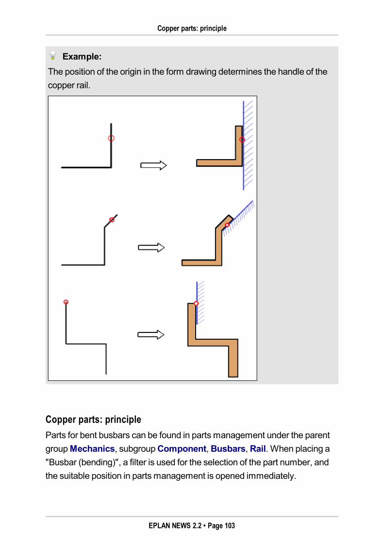
Copper parts: principle
Example:The position of the origin in the form drawing determines the handle of thecopper rail.
Copper parts: principleParts for bent busbars can be found in parts management under the parentgroupMechanics, subgroupComponent,Busbars,Rail. When placing a"Busbar (bending)", a filter is used for the selection of the part number, andthe suitable position in parts management is opened immediately.
EPLAN NEWS 2.2 • Page 103
Copper parts: principle
On theMounting data tab of the rail part, the values forWidth andDepthare entered. These values form the rectangular cross-section outline of thecopper rail. They are read out during the placement and assigned to a form.The form is the path along which a rectangular basic outline is moved inorder to shape the bent copper rail.
If the part is assigned anOutline (extrusion)with the file extension *.fp1 (tocreate a user-defined rail), instead of the values forWidth andDepth, thispart cannot be used for a bent copper rail. An error message is displayed dur-ing the placement.
On theDelivery length tab of the rail part, aDelivery length is entered forpurchased rail parts. This value is taken into account during the placement ofthe rail, so that the rail can be shaped only up to this value along the form.When the delivery length is reached, amessage is shown; in the design,another rail must be connected here.
Unchangeable copper items
The length, angle and bending positions of a placed copper item are gen-erally changeable. In practice, however, there is the requirement that copperitems are to be standardized or purchased in a fixed set form. Such parts,which are not variable, should not be possible to bemodified after place-ment.
This behavior can be controlled using thePrefabricated (ID 36011) propertythat can be activated on the item, e.g., in amacro. Once this property existsand has been activated, the copper item can no longer bemodified afterplacement. If this property is deactivated, the functions for editing copperitems can be applied again.
EPLAN NEWS 2.2 • Page 104
Busbar (bending): principle
Busbar (bending): principleFor the purposes of enclosure construction, additional copper items of dif-ferent forms are required besides the busbar systems. These itemsmust bevariable in terms of form, cross-section, and size, andmust be able to beadapted to the respective layout situation in the enclosure. Another require-ment is that such individually defined copper itemsmust be able to bemachined (bending, drilling, milling).
In EPLANPro Panel, copper items are realized with theBusbar (bending)function. Such an item is defined by the following:
One part (rail of defined height and width, or amacro with a rectangularcross-section)
One form (path of the rectangular basic form to shape the rail)
One bending radius for positions where the rail is to be bent.
If a "Busbar (bending)" is placed, individually or following an already placedcopper rail, in a layout space, this creates a copper bundle, a grouping ofplaced copper rails.
Each busbar in the copper bundle hasmounting surfaces that can be acti-vated automatically or directly and, thus, be used for the placement of otherrails.
If a "Busbar (bending)" is brought close to amounting surface for the purposeof placement, the item will rotate according to the alignment of themountingsurface.
EPLAN NEWS 2.2 • Page 105
Copper bundle: principle
Copper bundle: principleA copper item is always part of a copper bundle. A copper bundle is thus agrouping of placed copper items.
When a copper item is placed, it is entered in the layout space navigatorunder the hierarchy level copper bundles with a bundle name and a number.Below each bundle, the individual busbars are entered that make up the bun-dle. This first generated bundle is activated automatically. Each followingplaced copper item is assigned to the active bundle.
During the placement of a copper item, existing copper bundles can be acti-vated automatically or selectively in order to assign the item to the requiredbundle. If no bundle has been activated, the placement of the item generatesa new bundle. By pressing the [N] key during the placement, you can alsogenerate a new bundle.
Assignment to copper bundle
The assignment of the copper item to a copper bundle is saved in theCopper bundle property for copper items. This property can bemodified intheProperties (components): Part placement (3D) dialog. Using the [...],you can display the 3D object selection dialog. By selecting another, exist-ing bundle, you can assign the copper item to this bundle. The [New] buttongenerates a new bundle that is also activated in this way.
Show copper bundle
The separate showing of individual enclosure components is also possiblefor copper bundles. For this purpose, select in the layout space navigator themenu itemsPopup menu > Show > Copper.
Selection copper bundle or rail
If you highlight a copper item in the 3D display area, e.g., to display the prop-erties, it is the parent copper bundle that is initially selected. To select anindividual rail within the bundle, keep the [Shift] key pressed while selecting.
EPLAN NEWS 2.2 • Page 106
Editing a copper item: principle
Delete copper bundle
A copper bundle highlighted in the navigator or 3D display area can bedeleted using the [Del] key or viaEdit > Delete. Individual copper items aredeleted from a copper bundle by pressing the [Shift] key while selecting thepart in the 3D display area to be deleted.
Editing a copper item: principleTo edit copper items, there are special functions that can be used tomodifythe form of the item:
Change length
Change angle
Change bending positions
Add new bending position.
In addition, all the customary editing functions in EPLANPro Panel of thegraphical editors can also be applied to copper items:
Delete
Copy
Paste
Cut
Move
Duplicate
Edit properties
Unite
Rotate around axis.
With all editing functions, you can use the designmode to select a handle.
EPLAN NEWS 2.2 • Page 107
Copper unfold: principle
Copper unfold: principleAn unfold is a 2D representation of a copper item viewed from above in thestate prior to mechanical bending. Unfolds are placed on graphical pages.For each unfold, only one item is represented. Since the copper items proc-essed in EPLANPro Panel have a constant rectangular cross-section, anunfold will always display a rectangle as the outer outline.
In addition to the display of the outer form, the unfold contains information onthe bending positions. For this purpose, bending lines and bending extentsare displayed. Furthermore, the bending positions contain information on thebending angle and the direction of the bending.
The resulting unfolds – similar to themodel views – can be dimensioned andlabeled subsequently. The unfold is, thus, themanufacturing basis for thebendingmachine that processes the copper item further. The reports on themachining of copper items grab the information contained in the unfold and,thus, control themanufacturing on the NCmachine.
Unfolds can be edited andmodified with the same functions asmodel views:
Move contents
Center contents
Update
Block updates by activating the Frozen property.
EPLAN NEWS 2.2 • Page 108
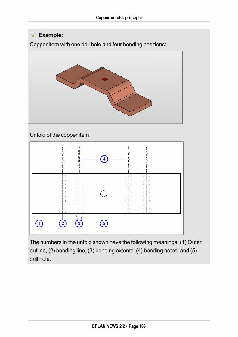
Copper unfold: principle
Example:Copper item with one drill hole and four bending positions:
Unfold of the copper item:
The numbers in the unfold shown have the followingmeanings: (1) Outeroutline, (2) bending line, (3) bending extents, (4) bending notes, and (5)drill hole.
EPLAN NEWS 2.2 • Page 109
Copper bundles in mounting lists
Unfolded total length
As soon as a copper item is placed in the layout space, the unfolded totallength of the copper item is determined according to internally set rules. Thecalculated unfolded total length is entered in the part reference data of thepart placement in the sameway it is done for a channel. With eachmod-ification to the item (length or angle change), the total length is updated. Theunfold is calculated from the unfolded total length and the adjustment valuesdefined in the settings in the bending table.
If the bending table does not contain thematerial thickness of a copper itemwith the relevant bending radii and bending angles, the total length cannot becalculated. This state is displayed in the properties of the busbar on theBend-ing positions tab in theStatus field.
After adjusting the bending angle or adjusting the bending table, theUpdatepart dimensions function should be executed for the affected item. Sub-sequently, the total length is re-calculated and entered in the part referencedata of the item.
Copper bundles in mounting listsFor the 3D part placements of a layout space, reports of theMounting listtype can be output in EPLANPro Panel. Mounting lists are used tomap in areport the hierarchical structure of amounting layout in the layout space. Thisreport can also be generated for copper bundles and copper items.
In such a function-based report, the copper bundles are evaluated for whichtheCreate mounting list (ID 36032) property has been activated in the prop-erty dialog. This property can be selected via property selection for all 3Dobjects (except for mounting surfaces). For a copper bundle with the acti-vated property, the output mounting list will show all copper items containedtherein. The listed objects are sorted by legend item by default.
EPLAN NEWS 2.2 • Page 110
Manufacturing integration
For more information onmounting lists, go to the online help and look up thesection "Mounting lists: Principle".
Manufacturing integration
Note:The extensionmodules "EPLANPro Panel - Production Copper DXF" and"EPLANPro Panel - Production Copper NC" are available as an option forEPLANPro Panel Professional. It does not matter whether EPLANProPanel Professional is installed as a stand-alone variant or as an add-on forEPLANElectric P8.
The necessary information for the bending processing of items can be trans-ferred from EPLANPro Panel Copper also for themanual manufacturing andcontrol of NC-based bending robots. At the transfer of themanufacturinginformation, a report is generated on the unfold of the copper item.
The two new extensionmodulesEPLANPro Panel - Production Copper DXFandEPLANPro Panel - Production Copper NC can be licensed as interfacesfor the respectivemachines. Using these interfaces, you can export the fol-lowing formats for machining purposes:
Export Copper DXF: Graphical export of the unfold in the DXF format
Export Copper NC: Export of the unfold in the XML format.
EPLAN NEWS 2.2 • Page 111
Other New Features for EPLAN Pro Panel
Other New Features for EPLAN Pro PanelExtended licensed add-ons for EPLAN Pro Panel ProfessionalFor this version, the scope of the stand-alone variant of EPLANPro PanelProfessional has been extended substantially. The following extensionmod-ules are now integral components of EPLANPro Panel Professional Stand-alone:
EPLANMulti Language Translation
EPLANProject Management
EPLANRevisionManagement.
To add further special functions to the stand-alone variant, you can licensethe following optional extensionmodules:
EPLANMulti User Management
EPLANProject Options
EPLANProject Processing
EPLANProject Reference
EPLANUser Rights Management.
Note:A detailed account of the EPLAN extensionmodules that are used in con-nection with EPLANPro Panel Professional can be obtained from the per-formance description for EPLANPro Panel Professional.
EPLAN NEWS 2.2 • Page 112
Inserting routing connections
In the next section, we also introduce the following new features for EPLANPro Panel:
"Inserting routing connections" on page "113"
"Modified settings for data import and routing connections" on page "114"
"Modifying origin of amounting surface" on page "115"
"Additional handle for busbar supports" on page "116".
Inserting routing connectionsIn addition to the routing connections generated during the automatic routingof connections, it is now possible to define the routing connectionsmanually.To do so, in the Insertmenu use the newRouting connectionmenu item.Thanks to this function, routing connections are generated, then routedautomatically, and shown in the layout space.
As a prerequisite for the 3D part placements in the layout space, you shouldhave generated a routing path network. As well, you should activate the pre-view of the connections to rule out that any duplicate routing connections canbe generated. After you have selected themenu items Insert > Routing con-nection, the view of the connection points will be activated. All defined con-nection points of the part placements shown in the layout space are thusvisible.
First, select the source of the connection. For this, you have the followingoptions:
Click one of the connection points of a part placement shown in the layoutspace.
Or click a part placement. Then, a list with the connection points of thispart placement is shown. Select a connection point here.
EPLAN NEWS 2.2 • Page 113
Modified settings for data import and routing connections
Then, proceed as before to select the target of the connection. Between theselected connection points of the source and target, a routing connection isgenerated, placed, and displayed in the preview of connections.
Note:Bymanually inserting a routing connection, a counterpiece is not automati-cally generated in themulti-line planning. Using the check run 005067, youcan check whether a routing connection generated in this way has acounterpiece in themulti-line schematic. If this is not the case, themissingsource and / or missing target should be added to the schematic with thecorresponding parts data (device) and connected via an autoconnectingline.
Modified settings for data import and routing connectionsThe settings dialogs for the import of devices and for the import of routing con-nections are now also available in the settings. For example, to make yourassignments for the import of devices, follow themenu pathOptions > Set-tings > Projects > "Project name" > Devices > Import.
All the settings for the routing connections have been combined in a newfolder. Below theProjects > "Project name" > Routing connections set-ting category, you will find the settings for the import of routing connections.You will also find that all other general settings for the routing connections(tabsWire termination processing, etc.) have beenmoved from theCon-nections settings folder to the newRouting connections folder.
EPLAN NEWS 2.2 • Page 114
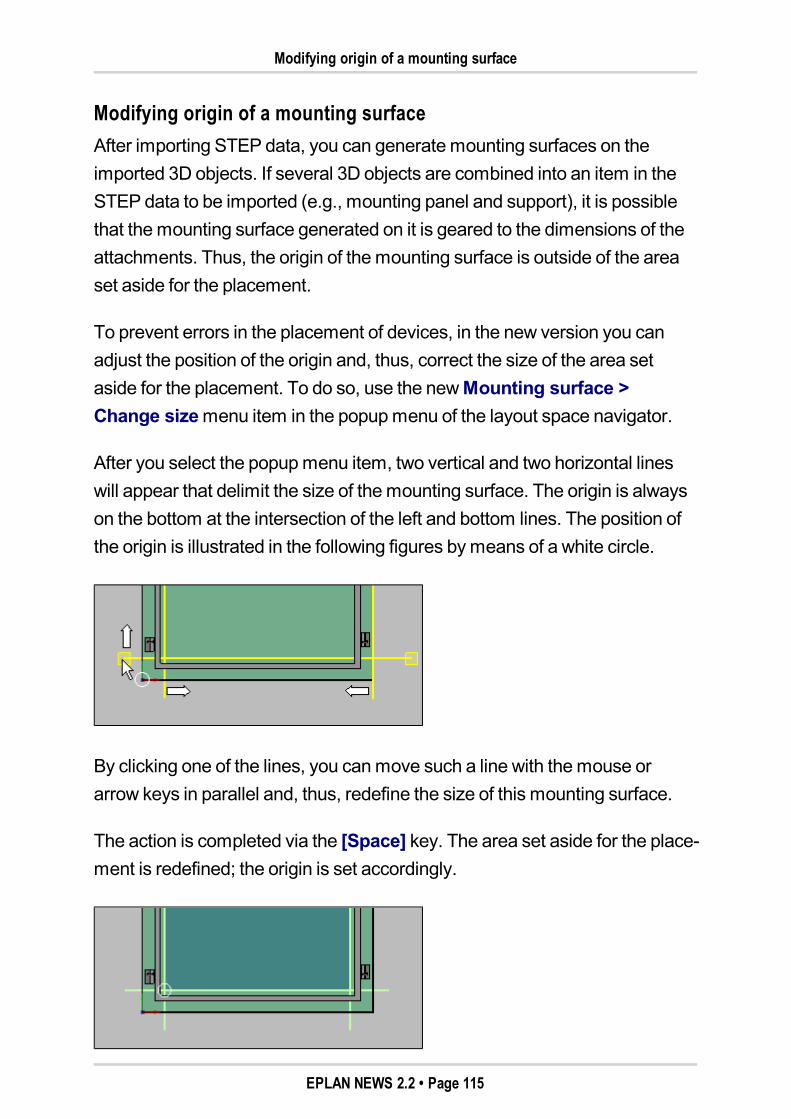
Modifying origin of a mounting surface
Modifying origin of a mounting surfaceAfter importing STEP data, you can generatemounting surfaces on theimported 3D objects. If several 3D objects are combined into an item in theSTEP data to be imported (e.g., mounting panel and support), it is possiblethat themounting surface generated on it is geared to the dimensions of theattachments. Thus, the origin of themounting surface is outside of the areaset aside for the placement.
To prevent errors in the placement of devices, in the new version you canadjust the position of the origin and, thus, correct the size of the area setaside for the placement. To do so, use the newMounting surface >Change sizemenu item in the popupmenu of the layout space navigator.
After you select the popupmenu item, two vertical and two horizontal lineswill appear that delimit the size of themounting surface. The origin is alwayson the bottom at the intersection of the left and bottom lines. The position ofthe origin is illustrated in the following figures bymeans of a white circle.
By clicking one of the lines, you canmove such a line with themouse orarrow keys in parallel and, thus, redefine the size of this mounting surface.
The action is completed via the [Space] key. The area set aside for the place-ment is redefined; the origin is set accordingly.
EPLAN NEWS 2.2 • Page 115

Additional handle for busbar supports
Additional handle for busbar supportsWhen inserting busbar systems for whose supports a graphical macro hasbeen stored in parts management, the handle of the graphical macro is nowused by default during placement. This way, for example, it is possible toachieve that the handle is located in the center of a drill hole in the support.
The default handles that are not defined in themacro can be selected in thePlacement options dialog or via the [A] key during placement.
Note:During the placing of an integrated busbar system, the handle is on the leftside of the support when entering the starting point. For the input of the endpoint, the handle is switched to "Right". When using amacro for the sup-ports, however, the handle from themacro for the starting and end point isused.
EPLAN NEWS 2.2 • Page 116
Special Topics EPLAN PPE
Special Topics EPLAN PPE
Extended Planning of Piping
Note:EPLANP&ID is both an option and an add-on for miscellaneous programvariants of the EPLAN platform, and it is also available as a stand-alonesystem. The "EPLANP&ID" add-on is available as an option for the fol-lowing program variants:EPLANElectric P8 Compact, EPLANElectric P8 Select,EPLANElectric P8 Professional, EPLANElectric P8 Professional+,EPLANFluid Compact, EPLANFluid, EPLANFluid Professional,EPLANPPE.For the following program variants, this add-on is part of the delivery scopeby default:EPLANElectric P8 Ultimate, EPLANPPEProfessional.
The new version substantially extends the planning of piping within EPLANP&ID. The information on process-engineering processes required for P&Idiagrams, such as raw-material media and their state size, can be stored onthe piping in the project bymeans of the new symbolsProcess definitionpoint / Process connection point. By using the new connection symbol Junc-tion, connections are created that comply with the logic in piping construc-tion.
Benefit:The new functions in EPLANP&ID allow for the convenient creation of P&Idiagrams for the display of process-engineering process / plant overviewswith relevant instrumentation. New project checks ensure data consis-tency, and allow for fast and error-free working.
EPLAN NEWS 2.2 • Page 117
Defining process data
Wediscuss the following topics in the next sections:
"Defining process data" on page "118"
"Junctions for piping" on page "122"
"Entering and checking cross-sections / diameters" on page "124"
"Connection numbering for piping" on page "126"
"Extensions to device selection" on page "126"
"Outputting process overview" on page "127"
"Improved graphical workingmethod" on page "127"
"NewP&I symbols" on page "128".
Defining process dataIn EPLAN, you can now define process-engineering process data in aproject. Themedia and states of suchmedia used in the process are definedbymeans of process definition points and process connection points. A proc-ess definition is identified by themedium.
You can place a process definition point on an autoconnecting line and, thus,assign process properties to the connection (piping) passing through belowsuch point. Use a process connection point to place the process definition atthe beginning of an autoconnecting line.
To insert these new symbols, select themenu items Insert > Process def-inition point or Insert > Process connection point. When you haveplaced the respective symbol on a page, the familiar properties dialog opens.
EPLAN NEWS 2.2 • Page 118
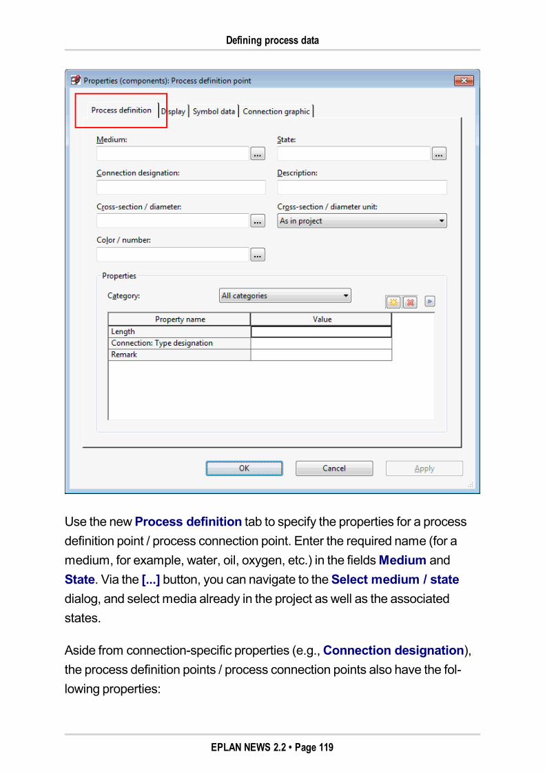
Defining process data
Use the newProcess definition tab to specify the properties for a processdefinition point / process connection point. Enter the required name (for amedium, for example, water, oil, oxygen, etc.) in the fieldsMedium andState. Via the [...] button, you can navigate to theSelect medium / statedialog, and select media already in the project as well as the associatedstates.
Aside from connection-specific properties (e.g.,Connection designation),the process definition points / process connection points also have the fol-lowing properties:
EPLAN NEWS 2.2 • Page 119
Defining process data
Pipe class (ID 22224)
Material (ID 22081)
Nominal width (ID 22225)
Nominal pressure level (ID 22226)
Standard (ID 22227)
Pressure (ID 31082)
Temperature (ID 31084)
Flow (ID 31085).
If the properties are not displayed in the property table, you will need to usethe property selection.
When connections are updated, the entered values for medium, state, andthe other listed properties are carried over to the connection. The values forthe propertiesMedium (ID 31068), State (process) (ID 31081), Pressure(ID 31082), Temperature (ID 31084), and Flow (ID 31085) can be displayedin the property dialog of the connection, but not modified.
Tip:In the list view of the connections navigator, too, themedium and state ofpiping (connection) can now be displayed. For this, realize an appropriatecolumn configuration via theConfigure columns popupmenu item.
Transfer of media and statesThemedia and states defined for a process behave in a way analogous tothe potentials and signals in electrical engineering. Accordingly, some func-tions for potentials and signals also apply to these process-engineering prop-erties.
EPLAN NEWS 2.2 • Page 120
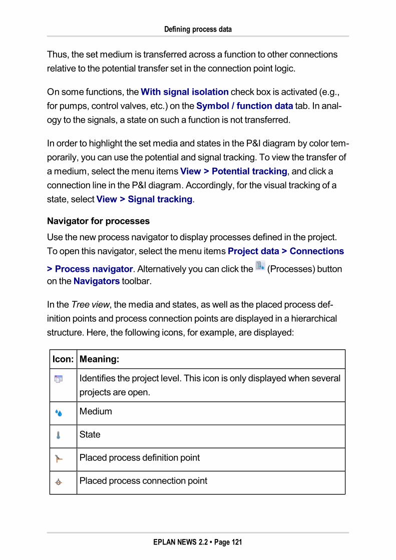
Defining process data
Thus, the set medium is transferred across a function to other connectionsrelative to the potential transfer set in the connection point logic.
On some functions, theWith signal isolation check box is activated (e.g.,for pumps, control valves, etc.) on theSymbol / function data tab. In anal-ogy to the signals, a state on such a function is not transferred.
In order to highlight the set media and states in the P&I diagram by color tem-porarily, you can use the potential and signal tracking. To view the transfer ofamedium, select themenu itemsView > Potential tracking, and click aconnection line in the P&I diagram. Accordingly, for the visual tracking of astate, select View > Signal tracking.
Navigator for processesUse the new process navigator to display processes defined in the project.To open this navigator, select themenu itemsProject data > Connections
> Process navigator. Alternatively you can click the (Processes) buttonon theNavigators toolbar.
In the Tree view, themedia and states, as well as the placed process def-inition points and process connection points are displayed in a hierarchicalstructure. Here, the following icons, for example, are displayed:
Icon: Meaning:
Identifies the project level. This icon is only displayed when severalprojects are open.
Medium
State
Placed process definition point
Placed process connection point
EPLAN NEWS 2.2 • Page 121
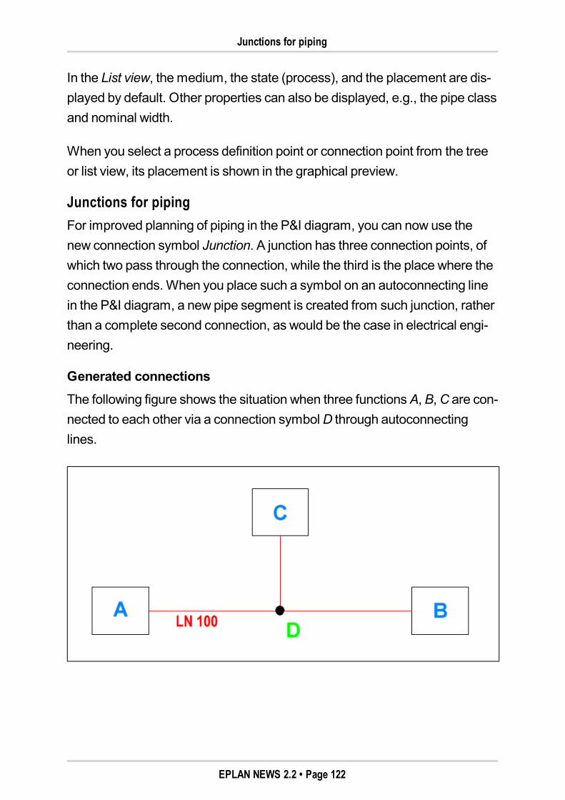
Junctions for piping
In the List view, themedium, the state (process), and the placement are dis-played by default. Other properties can also be displayed, e.g., the pipe classand nominal width.
When you select a process definition point or connection point from the treeor list view, its placement is shown in the graphical preview.
Junctions for pipingFor improved planning of piping in the P&I diagram, you can now use thenew connection symbol Junction. A junction has three connection points, ofwhich two pass through the connection, while the third is the place where theconnection ends. When you place such a symbol on an autoconnecting linein the P&I diagram, a new pipe segment is created from such junction, ratherthan a complete second connection, as would be the case in electrical engi-neering.
Generated connectionsThe following figure shows the situation when three functionsA, B,C are con-nected to each other via a connection symbolD through autoconnectinglines.
EPLAN NEWS 2.2 • Page 122
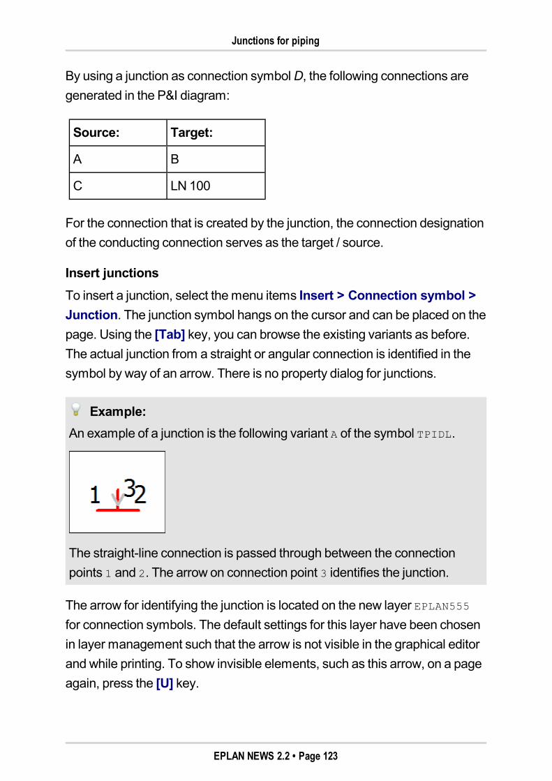
Junctions for piping
By using a junction as connection symbolD, the following connections aregenerated in the P&I diagram:
Source: Target:
A B
C LN 100
For the connection that is created by the junction, the connection designationof the conducting connection serves as the target / source.
Insert junctionsTo insert a junction, select themenu items Insert > Connection symbol >Junction. The junction symbol hangs on the cursor and can be placed on thepage. Using the [Tab] key, you can browse the existing variants as before.The actual junction from a straight or angular connection is identified in thesymbol by way of an arrow. There is no property dialog for junctions.
Example:An example of a junction is the following variant A of the symbol TPIDL.
The straight-line connection is passed through between the connectionpoints 1 and 2. The arrow on connection point 3 identifies the junction.
The arrow for identifying the junction is located on the new layer EPLAN555for connection symbols. The default settings for this layer have been chosenin layer management such that the arrow is not visible in the graphical editorand while printing. To show invisible elements, such as this arrow, on a pageagain, press the [U] key.
EPLAN NEWS 2.2 • Page 123
Entering and checking cross-sections / diameters
When inserting the symbol, the hidden elements are always visible, and thedisplayed arrow allows for the selection of the correct variant.
Tip:For junctions, the SPECIAL symbol library contains the two new symbolsTPIDA (junction at angular connection) and TPIDL (junction at straight-lineconnection). If, after selecting themenu items Insert > Connection sym-bol > Junction, you press the [Back] button, the symbol selection opens,and you can select one of these two special symbols.
Entering and checking cross-sections / diametersTo check cross-sections / diameters of functions and piping in a project, mis-cellaneous extensions have been added.
At the function:To enter the connection point cross-section / diameter at a function, youcan use in the property dialog the newConnection point cross-section/ diameter (all, depending on DT adoption) (ID 20297) property. If theproperty is not displayed in the property table, you will need to select itusing the property selection. In analogy to the connection point des-ignation, the individual connection point cross-sections / diameters arestated separated from each other by the "¶" character.
At the function templates:To enable these data to be stored at the function templates in partsmanagement, on the Function templates tab, theConnection pointcross-section / diameter column has been added to theDevice selec-tion (function templates) table. The values entered here are taken intoconsideration during the device selection. When inserting devices, thevalues are carried over from the function template to the function.
EPLAN NEWS 2.2 • Page 124
Entering and checking cross-sections / diameters
To enter data on a connection, use the existingCross-section / diameterfield. As well, you can also use the same property in a process definition pointor process connection point in order to carry over the values to a connection.
Tip:To display the connection point cross-sections / diameters entered on afunction in the schematic, you can use the newConnection point cross-section / diameter (all) (ID 20296) property. If you have selected this prop-erty in the property dialog in theDisplay tab for a property arrangement ofthe components, the individual connection point cross-sections / diametersare displayed on the function separated by semicolons ";".
Check runs for process dataDiffering connection point cross-sections / diameters on the targets of pipingor on piping and a connection point can be checked bymeans of the two newcheck runs 005073 and 005074.
To check the process data, you can use the following new project checkmes-sages in the "Connections" message class:
Message 005073 "Different connection point cross-section / diameter oftargets"
Message 005074 "Different connection point cross-section / diameter ofconnection and connecting point"
Message 005075 "Several process definitions within a process"
Message 005076 "Conflict between identical process definitions"
Message 005077 "Process connection or definition point without spec-ification of themedium"
Message 005078 "Connection without specification of process"
Message 005079 "Several process state definitions on a process".
EPLAN NEWS 2.2 • Page 125
Connection numbering for piping
In addition, the two project checks 005044 and 005045 to check identical con-nection designations have been extended and renamed. These now alsotake into account processes or process states.
Connection numbering for pipingThe numbering of connections on a page of the "P&I diagram" page type hasbeen possible for some time. For electrical engineering and process engi-neering, we recommend a separate numbering of connections (e.g., by wayof schemes with different connection filters).
Given the analogy of the process definition with potentials and signals, thesettings for potentials and signals can be carried over to the connection num-bering for piping. In theConnection numbering: Formats dialog, therefore,some options in the drop-down list Extent have been renamed (now: "Signal/ state", "Potential / process"). In addition, you have a new format element atyour disposal: the "Data of the process" entry. You can use this now to selectalso process-engineering properties (Pipe class, Nominal width, etc.) for thenumbering.
Extensions to device selectionIn order to be able to assign, in a targeted fashion, to a device process-engi-neering parts during device selection on the basis of technical data, the func-tion templates in parts management have been extended. Besides thealreadymentioned propertyConnection point cross-section / diameter, itis now possible to store for parts from the "Process engineering" genericproduct group also data for thePipe class property in a function template.
In addition, you can now specifically filter for process-engineering parts formain functions from process engineering during device selection. For this pur-pose, theSettings: Device selection dialog has been extended to includetheProcess engineering tab. Here, you can use the following properties asselection criteria for parts:
Connection point designation
Connection point description
EPLAN NEWS 2.2 • Page 126
Outputting process overview
Connection point cross-section / diameter
Technical characteristics
Pipe class
Relevant to safety
Intrinsically safe.
Outputting process overviewTo generate reports on process data, you can use the new report type "Proc-ess overview" in theSelect report dialog. In such a report, themedia, states,and properties such as pressure, flow, etc. that are defined in a process-engi-neering process are displayed.
In outputting this new report type, the form is used that was specified in theproject-specificSettings: Output to pages dialog for the new "Process over-view (*.f37)" form type. An appropriate form is supplied in themaster datafor this new report.
Improved graphical working methodTo achieve better support for the graphical workingmethod, it is now possibleto delete completely the PCT loops and loop functions placed on a projectpage bymeans of the graphical editor.
Using theDelete placementmenu item, you can now remove the place-ment from the project page. The PCT loop or loop function is retained inthe functional view navigator.
Via theDeletemenu item, both the placed function and the associatedobject are deleted in the functional view navigator.
The EPLANPPE object is not deleted in the functional view navigator if thereare references (assigned functions or project pages, another graphical place-ment) to this object. In such a case, only the placement on the project page isremoved.
EPLAN NEWS 2.2 • Page 127
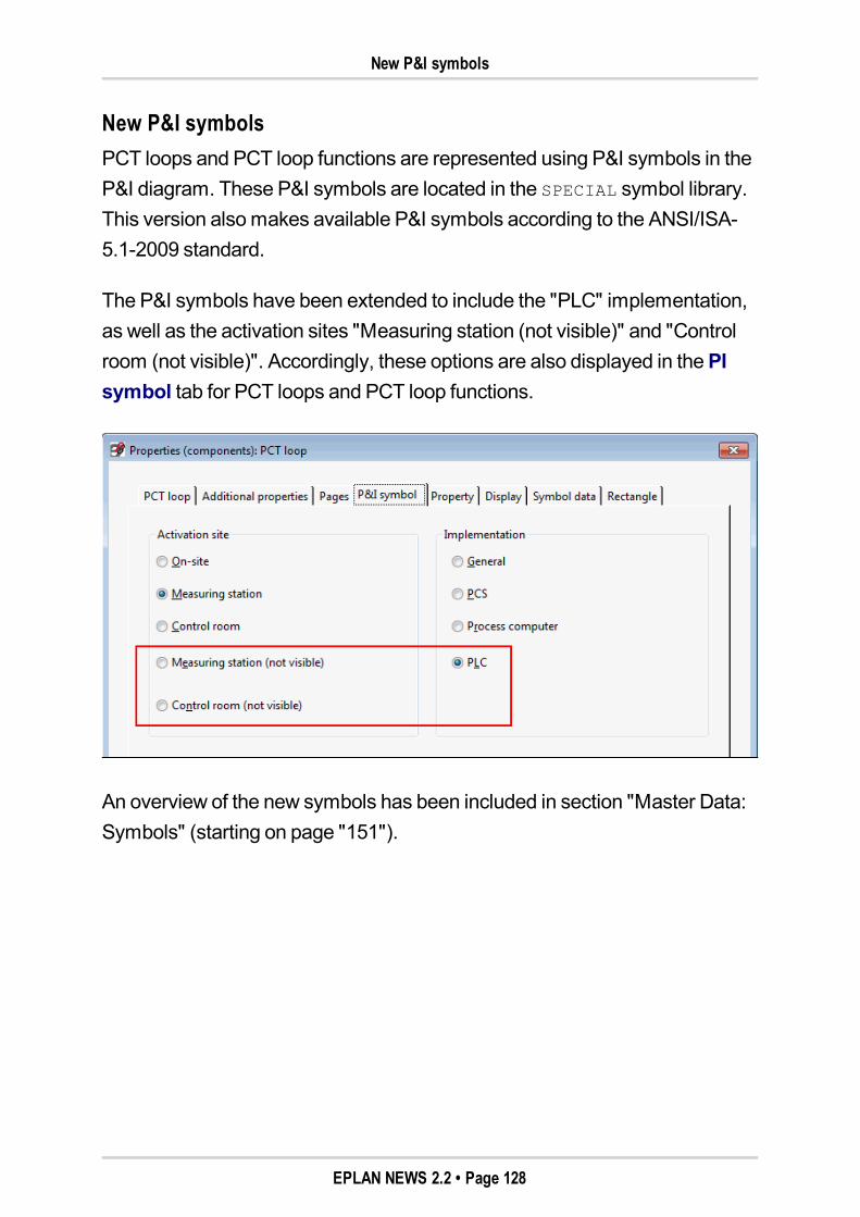
New P&I symbols
New P&I symbolsPCT loops and PCT loop functions are represented using P&I symbols in theP&I diagram. These P&I symbols are located in the SPECIAL symbol library.This version alsomakes available P&I symbols according to the ANSI/ISA-5.1-2009 standard.
The P&I symbols have been extended to include the "PLC" implementation,as well as the activation sites "Measuring station (not visible)" and "Controlroom (not visible)". Accordingly, these options are also displayed in thePIsymbol tab for PCT loops and PCT loop functions.
An overview of the new symbols has been included in section "Master Data:Symbols" (starting on page "151").
EPLAN NEWS 2.2 • Page 128
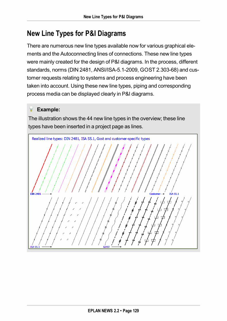
New Line Types for P&I Diagrams
New Line Types for P&I DiagramsThere are numerous new line types available now for various graphical ele-ments and the Autoconnecting lines of connections. These new line typesweremainly created for the design of P&I diagrams. In the process, differentstandards, norms (DIN 2481, ANSI/ISA-5.1-2009, GOST 2.303-68) and cus-tomer requests relating to systems and process engineering have beentaken into account. Using these new line types, piping and correspondingprocessmedia can be displayed clearly in P&I diagrams.
Example:The illustration shows the 44 new line types in the overview; these linetypes have been inserted in a project page as lines.
EPLAN NEWS 2.2 • Page 129
Extensions in layer management
Benefit:The new line types help keep the creation of plant overviews (P&ID,P&I schemes) and the documentation thereof in accordance with the stand-ards. The information content and transparency of plant overviews havebeen enhanced thanks to the corresponding graphical display. The customdefinition of new layers in combination with the line types allows for com-pany-internal standardization in the area of P&ID creation. The easy selec-tion and use of the differing line types and layers accelerates andstandardizes your planning process.
Extensions in layer managementFor each of the new 44 line types, a new separate layer has been provided inlayer management. You can find these layers below the tree structure layerSymbol graphic > Connection symbols > Autoconnecting > P&ID. Thesettings for the layers EPLAN750 to EPLAN793 have been selected such thattheymeet the requirements of miscellaneous standards.
In addition, you can select one of the new line types for each of the existinglayers, or any new layer to be created. For this, you can use also the new linetypes available from the drop-down list in the Line type column. Thisselected line type is then used by default for the respective line in a project-widemanner.
Other default values for line thickness and pattern length
Tomap the defaults from the standards to be considered better, the two dis-play properties Line thickness andPattern length have been extended toinclude further default values.
You can select the following additional default values from the drop-downlists of the Line thickness property:
0.20mm / 0.0079 In
0.40mm / 0.0157 In.
EPLAN NEWS 2.2 • Page 130
Application in the P&I diagram
You can select the following additional default values from the drop-downlists of thePattern length property:
1.50mm / 0.0591 In
12.00mm / 0.4724 In
20.00mm / 0.7874 In
24.00mm / 0.9449 In
28.00mm / 1.1024 In
32.00mm / 1.2598 In.
Note:Whether values here are entered inmm or inches depends on theDis-played unit of length setting in the user settings.
Application in the P&I diagramPreviously, the data of piping wasmanaged in the P&I diagram via con-nection definition points that were placed on autoconnecting lines. For thesake of improved piping design in EPLANP&ID, the new special symbols"Process definition points" are now used instead.
To use one of the new line types on an autoconnecting line in a P&I diagram,place such a process definition point on this line. In the property dialog of theprocess definition point, change to theConnection graphic tab, and selectfor the Layer field the required layer (e.g., the layer EPLAN759, Symbol
graphic .Connection symbols.Autoconnecting.P&ID.Flammable
gases).
After updating the connections, the properties of the respective line type,specified on the layer, are displayed in the P&I diagram. Thus, for example,an autoconnecting line for flammable gases (layer EPLAN759) would be dis-played in orange.
EPLAN NEWS 2.2 • Page 131
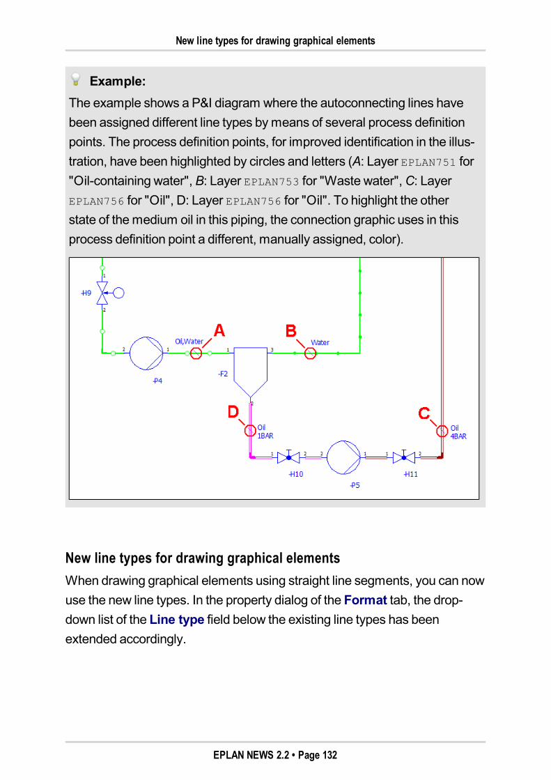
New line types for drawing graphical elements
Example:The example shows a P&I diagram where the autoconnecting lines havebeen assigned different line types bymeans of several process definitionpoints. The process definition points, for improved identification in the illus-tration, have been highlighted by circles and letters (A: Layer EPLAN751 for"Oil-containing water", B: Layer EPLAN753 for "Waste water",C: LayerEPLAN756 for "Oil", D: Layer EPLAN756 for "Oil". To highlight the otherstate of themedium oil in this piping, the connection graphic uses in thisprocess definition point a different, manually assigned, color).
New line types for drawing graphical elementsWhen drawing graphical elements using straight line segments, you can nowuse the new line types. In the property dialog of the Format tab, the drop-down list of the Line type field below the existing line types has beenextended accordingly.
EPLAN NEWS 2.2 • Page 132
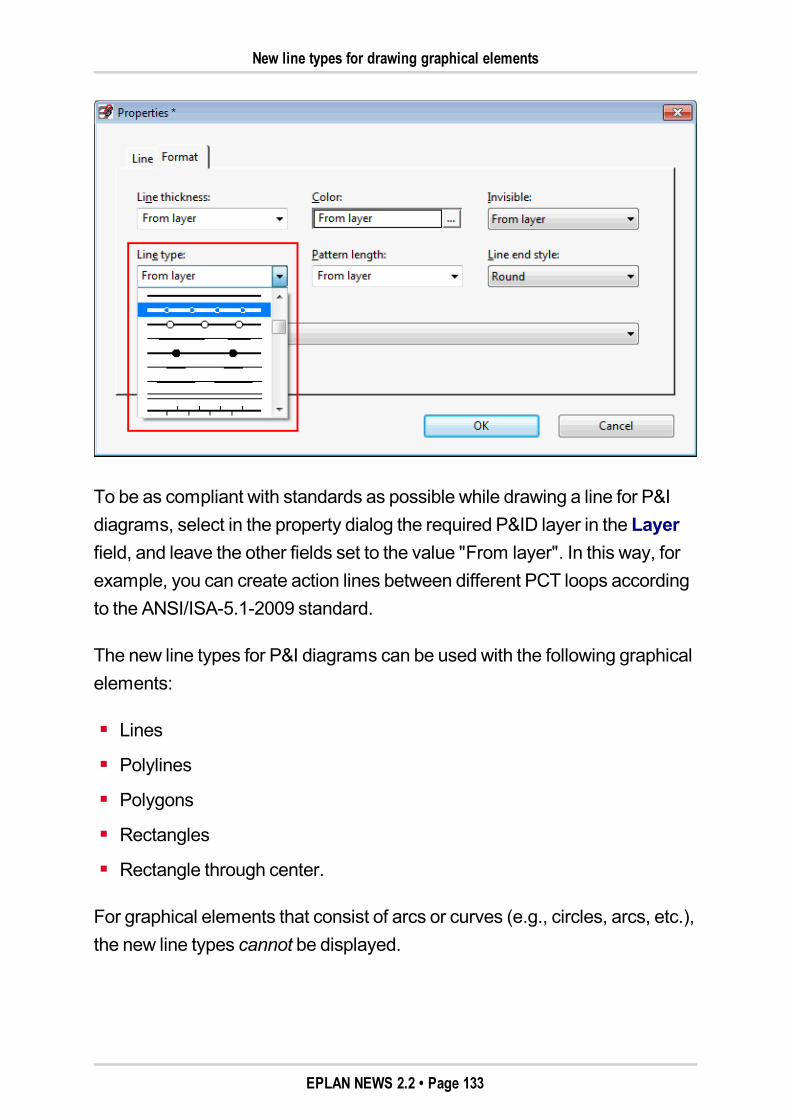
New line types for drawing graphical elements
To be as compliant with standards as possible while drawing a line for P&Idiagrams, select in the property dialog the required P&ID layer in the Layerfield, and leave the other fields set to the value "From layer". In this way, forexample, you can create action lines between different PCT loops accordingto the ANSI/ISA-5.1-2009 standard.
The new line types for P&I diagrams can be used with the following graphicalelements:
Lines
Polylines
Polygons
Rectangles
Rectangle through center.
For graphical elements that consist of arcs or curves (e.g., circles, arcs, etc.),the new line types cannot be displayed.
EPLAN NEWS 2.2 • Page 133
New line types for drawing graphical elements
Note:If one of the new line types is set for a graphical element that consists ofarcs or curves, this line type will be ignored, and the line will be displayedas a continuous line. Whether the line type has been determined directly inthe Line type field or via the selected layer does not matter here. All othersettings for the line (line thickness, color, etc.) are retained.
The following special features apply to the handling of the new line types:
Roundings:If the line segments of a polyline or the corner of a rectangle are rounded,no new line type will be used for the rounding. In such a case, the round-ing will be displayed as a continuous line with the set line thickness ancolor.
Additional graphics:Fixedmeasurements are used for the additional graphics (circles,crosses, etc.) applied to the new line types. In case of substantial changes(e.g., to the pattern length or line thickness), this can cause these addi-tional graphics to be no longer recognizable. In addition, double lines areonly displayed as single lines in the case of very small line thicknesses.
Line patterns:When changing the length of a line, the line pattern is fitted in between thestarting and end points in a centeredmanner. The partial lines at the startand end of a line up to the respective additional graphic are always of thesame length.
Line end styles:Different line end styles (round, rectangular, flat) can be displayed for alllines with a "base line". For line types that consist of several lines (doublelines, etc.) or only of additional graphics, this behavior is not supported. Aflat line end is displayed for such lines.
EPLAN NEWS 2.2 • Page 134
Influencing Distance While Drawing PCT Loops
Export of the new line types
The new line types can also be output during export to the different formats(DXF / DWG, image file, PDF). For a DXF / DWG export to AutoCAD, youmust – as before – create an assignment table in the settings in which theEPLAN layers are assigned to the layer names used in AutoCAD.
Note:In case of a DXF / DWG export and subsequent import in AutoCAD, it canhappen that lines with the new line types are displayed differently if therespective AutoCAD version does not support these line types.
Influencing Distance While Drawing PCT LoopsTheDraw PCT loops function allows you to place one or several PCT loopsautomatically in the schematic bymeans of window or pagemacros. Pre-viously, themacros were placed with a distance specified by the program. Inthe newEPLANPPE version, you can nowmodify the distance.
The distance is specified in theSettings: PCT loops dialog bymeans of thenew group boxDistance in drawing PCT loops (menu path:Options >Settings > Projects > "Project name" > PPE > PCT loops).
EPLAN NEWS 2.2 • Page 135
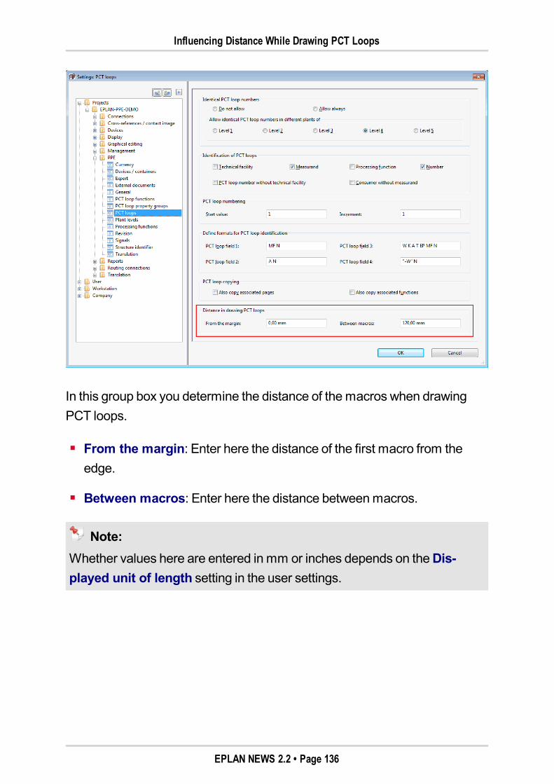
Influencing Distance While Drawing PCT Loops
In this group box you determine the distance of themacros when drawingPCT loops.
From the margin: Enter here the distance of the first macro from theedge.
Between macros: Enter here the distance betweenmacros.
Note:Whether values here are entered inmm or inches depends on theDis-played unit of length setting in the user settings.
EPLAN NEWS 2.2 • Page 136
New Features in the EPLAN Data Portal
New Features in the EPLAN Data Portal
At the same time as the release of the new version of the EPLAN platform, anew version of the EPLANData Portal with increased functionality has alsobeen released.
Our Internet portal for device data – the EPLANData Portal – supplies youwith themaster data of knownmanufacturers for the direct application to theEPLAN platform. In addition to alphanumeric parts data, among other infor-mation this master data also contains schematic macros, multilingual partsinformation, preview images, documents, etc. The data, supplied by theman-ufacturers, is directly integrated into the EPLAN platform when downloaded.
In version 2.2 of the EPLAN platform, the EPLANData Portal is available inthe following program variants:
EPLANElectric P8
EPLANFluid
EPLANPPE
EPLANPro Panel Professional
EPLANEducation.
In order to access the portal productively after installing a program variant,you will require a valid software service agreement for your EPLAN license.For a quick part search, you can also go directly to the website"http://eplandata.de/portal/".
After creating a user account, open the navigator of the EPLANData Portalby selecting from theUtilitiesmenu themenu itemsData Portal > Navi-gator.
EPLAN NEWS 2.2 • Page 137
New Features in the EPLAN Data Portal
Notes:Youmust be connected to the Internet in order to use the EPLANDataPortal, and youmust make sure that access is not prevented by a fire-wall or any other security mechanism! If you have problems, you shouldfirst check your firewall, virus scanner, or proxy settings.
Make sure that the EPLANData Portal has been approved for MicrosoftInternet Explorer 8 and Internet Explorer 9.
An overview of the main new features of the EPLAN Data Portal:
Even more data and manufacturersThe amount and scope of item data in the EPLANData Portal is con-stantly growing. Other manufacturers (e.g., EKF electrotechnica, WielandElectric) have been added to the list of over 45 component man-ufacturers. Manufacturers already established in the portal continuallyadd to the extent of their data in the EPLANData Portal.
Installation together with the EPLAN platformThe EPLANData Portal is more closely integrated with the EPLAN plat-form than before. If you now install a program variant of the EPLAN plat-form (e.g., EPLANElectric P8), the current version of the EPLANDataPortal will be installed at the same time.
Benefit:There is no need anymore for an additional installation of the EPLANDataPortal. You can access the EPLANData Portal directly from the EPLANplatform.
EPLAN NEWS 2.2 • Page 138
New Features in the EPLAN Data Portal
Highlighted manufacturers in the manufacturers' listNow, manufacturers can be positioned in a special area at the top of themanufacturers' list for a specific period of time. Whether to list man-ufacturers in this area, who they are, how longmanufacturers will be high-lighted for, and what to name the data header area for the special area –these are the questions that will be specified by the administrators of theEPLANData Portal at EPLAN. A highlightedmanufacturer will also con-tinue to be listed in the "normal" overview of all manufacturers.
Benefit:Highlightedmanufacturers show the user whichmanufacturers are new inthe EPLANData Portal or which ones are important for him.
Barcode as additional part informationNowmanufacturers can provide further information on the parts in thedetailed view by supplying a barcode. In theBarcode field, both the bar-code number and the barcode type are displayed. The entries are sep-arated by a blank (e.g., 12345678 EAN) and correspond to the propertiesof the same name in parts management on thePrices / Other tab. Inaddition, the search in the EPLANData Portal has also been extended toinclude the "Barcode" criterion.
Simplified characteristicsIn this version, the characteristics of parts data have been simplified. Boththeir designations, which now describe the data content, and their iconshave been adapted to the EPLAN platform. Characteristics (e.g., orderdata stored on the parts bymanufacturers, function templates, etc.) canbe used as filter criteria or for searches.
EPLAN NEWS 2.2 • Page 139
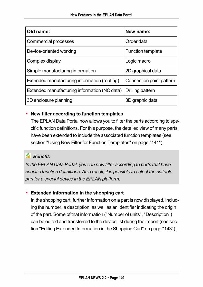
New Features in the EPLAN Data Portal
Old name: New name:
Commercial processes Order data
Device-oriented working Function template
Complex display Logic macro
Simplemanufacturing information 2D graphical data
Extendedmanufacturing information (routing) Connection point pattern
Extendedmanufacturing information (NC data) Drilling pattern
3D enclosure planning 3D graphic data
New filter according to function templatesThe EPLANData Portal now allows you to filter the parts according to spe-cific function definitions. For this purpose, the detailed view of many partshave been extended to include the associated function templates (seesection "Using NewFilter for Function Templates" on page "141").
Benefit:In the EPLANData Portal, you can now filter according to parts that havespecific function definitions. As a result, it is possible to select the suitablepart for a special device in the EPLAN platform.
Extended information in the shopping cartIn the shopping cart, further information on a part is now displayed, includ-ing the number, a description, as well as an identifier indicating the originof the part. Some of that information ("Number of units", "Description")can be edited and transferred to the device list during the import (see sec-tion "Editing Extended Information in the Shopping Cart" on page "143").
EPLAN NEWS 2.2 • Page 140
Using New Filter for Function Templates
Benefit:The number of main and accessory parts determined in the Rittal-Thermconfigurator, as well as the project name in Rittal Therm, are now also car-ried over to the shopping cart of the EPLANData Portal.
For information on all new products, visit our website "www.eplan.de/portal-news". Information on new functionalities is also available in the online helpfunction of the EPLANData Portal server.
Using New Filter for Function TemplatesOnmany parts of the EPLANData Portal, the associated function templatesare now stored. The function templates are listed in a table format in thedetailed view of a part as the bottom item.
Click one of the listed function templates to filter according to the respectivefunction definition. The selected function definition is shown in the filter areaabove the list view in the new Function template filter, and the list is filteredbased on this criterion. A part is listed when it contains the "searched" func-tion definition in one of its function templates.
If a part has several different function templates, you can now filter the portalfor such a part. To filter for all function definitions of a part, in the detailedview click the plus sign located next to the Function template entry. In theFunction template filter, then, several function definitions are listed. Sub-sequently, all suitable parts are listed in the parts list. Parts whose functiontemplates are the best fit for the function definitions listed in the filter will belisted at the top positions of the list.
EPLAN NEWS 2.2 • Page 141
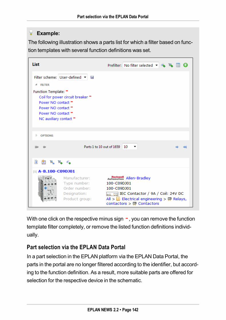
Part selection via the EPLAN Data Portal
Example:The following illustration shows a parts list for which a filter based on func-tion templates with several function definitions was set.
With one click on the respectiveminus sign , you can remove the functiontemplate filter completely, or remove the listed function definitions individ-ually.
Part selection via the EPLAN Data PortalIn a part selection in the EPLAN platform via the EPLANData Portal, theparts in the portal are no longer filtered according to the identifier, but accord-ing to the function definition. As a result, more suitable parts are offered forselection for the respective device in the schematic.
EPLAN NEWS 2.2 • Page 142
Editing Extended Information in the Shopping Cart
Filter by accessories in the part selection
If a device has already been assigned a part, on the basis of this part, thenewAccessories for filter is set for a subsequent part selection for anotherpart via the EPLANData Portal. Using this filter, EPLANData Portal filters forall parts that are accessory parts for the part already assigned.
Editing Extended Information in the Shopping CartYou can now list a part in the shopping cart multiple times. To differentiatethe individual parts in the shopping cart better, you can now store further infor-mation on a part, such as "Number of units" or "Description". This infor-mation is carried over to the propertiesNumber allowed andDevicedescription during the import from parts to the device list of the EPLAN plat-form.
Also displayed is the origin of the part. Parts that were added to the shoppingcart via the Rittal Therm configurator are given the identifier "RTH", and theother parts from the Data Portal the identifier "EDP". When carrying overparts from the Rittal Therm configurator to the shopping cart, the number ofparts and the project name from Rittal Therm are also applied to theextended information.
To edit the extended information of parts in the shopping cart, click the new
button (Edit shopping cart). Subsequently, a view of the shopping cart isdisplayed where the fieldsNumber of units andDescription are validated,allowing you to edit them. Click the [Save] button to apply the changed infor-mation.
EPLAN NEWS 2.2 • Page 143
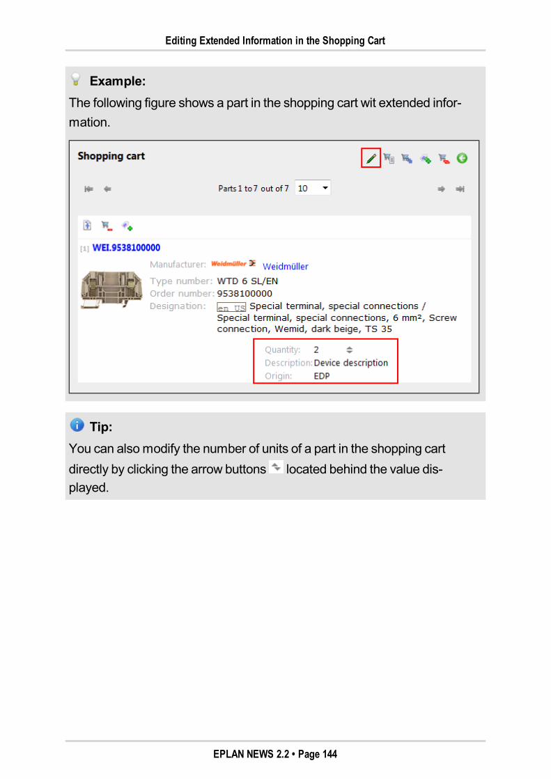
Editing Extended Information in the Shopping Cart
Example:The following figure shows a part in the shopping cart wit extended infor-mation.
Tip:You can alsomodify the number of units of a part in the shopping cartdirectly by clicking the arrow buttons located behind the value dis-played.
EPLAN NEWS 2.2 • Page 144
New Features in the "EPLAN API Extension" Extension Module
New Features in the "EPLAN API Extension"Extension Module
Note:The "EPLANAPI Extension" extensionmodule is available as an option aspart of our EPLANAPIDeveloperNetwork (EADN) as a developer's pack-age for the following program variants:EPLANElectric P8 Professional, EPLANElectric P8 Professional+,EPLANElectric P8 Ultimate, EPLANFluid, EPLANFluid Professional,EPLANPPE, EPLANPPEProfessional, EPLANPro Panel Professional.
A unified, and especially high-performance, programming interface (API,ApplicationProgramming Interface) is available for EPLAN platform prod-ucts. This extensionmodule – the EPLANAPI – allows you to develop yourown customized solutions in collaboration with EPLAN or other partners. Formore information on EPLANAPI and the EADN, visit the EPLANwebpagesunder the heading "Services > EPLANAPI Developer Network".
The following section provides information on the various new features ofEPLANAPI. To use the newEPLANAPI version to develop your own appli-cations, you will require theMicrosoft .NET Framework 4.0.
Removal of outdated methods and properties
Due to the ongoing improvements to the EPLAN platform, somemethodsand properties of EPLANAPI are no longer needed. In the new version ofEPLANAPI, the followingmethods and properties, which were outdatedalready in Version 1.8, have been removed:
In the class Connection:
AddArticle(string strArticleNR)
AddArticle(string strArticleNR, string strVariantNR,
Uint32 nCount).
EPLAN NEWS 2.2 • Page 145
New Features in the "EPLAN API Extension" Extension Module
In the class DeviceService:
ExportDeviceList(Project oProject, string strEx-
portFilePath)
ExportDeviceList(string strFullLinkFileName, string strEx-
portFilePath)
ImportDeviceList(Eplan::EplApi::DataModel::Project oPro-
ject, string strImportFilePath)
ImportDeviceList(string strFullLinkFileName string strIm-
portFilePath).
In the class Function:
AddArticle(string strArticleNR)
AddArticle(string strArticleNR, string strVariantNR,
Uint32 nCount)
HasLocalLogicalDefinition
SymbolType.
In the class MountingPanelService:
CreateArticlePlacement(string strPartNumber, PointD pLo-
cation).
In the class Pen:
DependsOnLayer.
In the class Project:
AddArticle(string strArticleNR)
AddArticle(string strArticleNR, string strVariantNR,
Uint32 nCount)
Objects(Filters.Part).
EPLAN NEWS 2.2 • Page 146
New Features in the "EPLAN API Extension" Extension Module
In the class ProjectManagement:
CompressProject(Project oProject, string strConfigScheme,
string strFilterScheme, bool bUseFilter)
CompressProject(string strFullLinkFileName string strCon-
figScheme string strFilterScheme, bool bUseFilter).
In the class Renumber:
DeviceTags(Function[] pFunctions, string strFilterScheme,
bool bUseFilter, Int32 eDeviceTagKind, string strScheme,
Int32 nStartValuePerIdentifier, Int32 nIn-
crementPerIdentifier)
DeviceTags(Project pProject, string strFilterScheme, bool
bUseFilter, Int32 eDeviceTagKind, string strScheme-
PerIdentifier, Int32 nStartValuePerIdentifier, Int32 nIn-
crementPerIdentifier).
In the class SelectionSet:
GetSelection().
In the class Shielding:
Shielding.Create(Page page).
In the class TextBase:
BoxLocation.
In addition, the followingmethods and properties have been removed fromthe Location class:
Create(Eplan::EplApi::DataModel::Project oProject)
SetParent(Location pParent)
HierarchyId.
EPLAN NEWS 2.2 • Page 147
New Features in the "EPLAN API Extension" Extension Module
Thesemethods and properties caused problems in the past, and weremarked as outdated for version 2.1.
Find filtered PLC connection points
The DMObjectsFinder class of EPLANAPI now comes with the newGetPLCTerminalsWithFilterSchememethod. Use this method to find PLCconnection points for the PLC navigator that remain when using a filterscheme.
Define defined working sections
EPLANAPI can now be used to divide EPLAN projects into defined workingsections. For this purpose, the new ProjectSections class has been addedto the Eplan.EplApi.DataModel namespace.
Functional placing of macros
Thanks to the newEPLANAPI, functional placing of macros in operationalsequence sheets is now possible. The new PlaceFunctionalMacromethodhas been added to the Function class for this purpose.
Functional placing of functions
Using the PlaceAtmethod from the Function class, it is now possible toplace functions with the "Functional" representation type correctly in therequired operational sequence sheet.
Generate PLC schematic
In the EPLAN API, you can now also generate a PLC schematic. (In the userinterface, this corresponds to themenu pathProject data > PLC > Gen-erate schematic.) The new GenerateSchematicmethod in the PlcSer-vice class is available for this.
EPLAN NEWS 2.2 • Page 148

New Features in the "EPLAN API Extension" Extension Module
Generate individual report pages
When creating a report for a project bymeans of EPLANAPI in the past, youcould only create a report for the total project, update reports or generateembedded reports. Now, you can generate individual report pages viaEPLANAPI, thanks to the new CreateReportmethod in the Reports class.
In addition, the new CreateReportsFromTemplatesmethod has beenadded to the same class. Using this method, you can create reports for thetemplates of one or several report types.
EPLAN NEWS 2.2 • Page 149
New Features in the Master Data
New Features in the Master Data
Extended Synchronization of Project Master DataFor the synchronization of the project master data with the system masterdata, you can now switch between different directories for the system masterdata.
Benefit:When synchronizing project master data, it is nowmore transparent to seethe directory where the system master data is stored. Data synchronizationis now faster when switching between directories.
For this purpose, theSynchronize master data - <Project name> dialogfor the list of system master data has been extended to include the drop-down listDirectories. (A possible menu path to this dialog is, for example,Utilities > Master data > Synchronize current project.)
You can select various directories for master data synchronization from thisdrop-down list. To be able to do this, youmust first have saved these direc-tory settings as a scheme. This may be useful if you are using differentmaster data directories for different companies / customers.
Click the [...] button located next to the drop-down list in order to open theSet-tings: Directories dialog. This dialog displays the set directories for the sys-tem master data. If necessary, you canmodify these settings and create anew scheme for the directories.
EPLAN NEWS 2.2 • Page 150
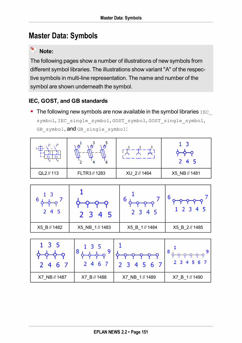
Master Data: Symbols
Master Data: Symbols
Note:The following pages show a number of illustrations of new symbols fromdifferent symbol libraries. The illustrations show variant "A" of the respec-tive symbols in multi-line representation. The name and number of thesymbol are shown underneath the symbol.
IEC, GOST, and GB standards
The following new symbols are now available in the symbol libraries IEC_symbol, IEC_single_symbol, GOST_symbol, GOST_single_symbol,GB_symbol, and GB_single_symbol:
QL2 // 113 FLTR3 // 1283 XU_2 // 1464 X5_NB // 1481
X5_B // 1482 X5_NB_1 // 1483 X5_B_1 // 1484 X5_B_2 // 1485
X7_NB // 1487 X7_B // 1488 X7_NB_1 // 1489 X7_B_1 // 1490
EPLAN NEWS 2.2 • Page 151
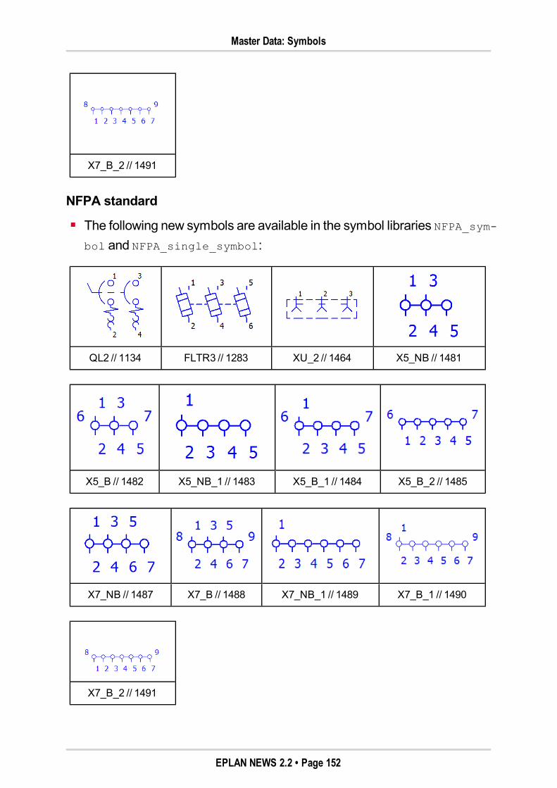
Master Data: Symbols
X7_B_2 // 1491
NFPA standard
The following new symbols are available in the symbol libraries NFPA_sym-bol and NFPA_single_symbol:
QL2 // 1134 FLTR3 // 1283 XU_2 // 1464 X5_NB // 1481
X5_B // 1482 X5_NB_1 // 1483 X5_B_1 // 1484 X5_B_2 // 1485
X7_NB // 1487 X7_B // 1488 X7_NB_1 // 1489 X7_B_1 // 1490
X7_B_2 // 1491
EPLAN NEWS 2.2 • Page 152
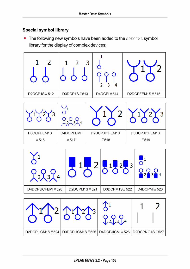
Master Data: Symbols
Special symbol library
The following new symbols have been added to the SPECIAL symbollibrary for the display of complex devices:
D2DCP1S // 512 D3DCP1S // 513 D4DCPI // 514 D2DCPFEM1S // 515
D3DCPFEM1S
// 516
D4DCPFEMI
// 517
D2DCPJICFEM1S
// 518
D3DCPJICFEM1S
// 519
D4DCPJICFEMI // 520 D2DCPM1S // 521 D3DCPM1S // 522 D4DCPMI // 523
D2DCPJICM1S // 524 D3DCPJICM1S // 525 D4DCPJICMI // 526 D2DCPNG1S // 527
EPLAN NEWS 2.2 • Page 153
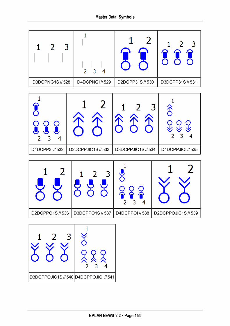
Master Data: Symbols
D3DCPNG1S // 528 D4DCPNGI // 529 D2DCPP31S // 530 D3DCPP31S // 531
D4DCPP3I // 532 D2DCPPJIC1S // 533 D3DCPPJIC1S // 534 D4DCPPJICI // 535
D2DCPPO1S // 536 D3DCPPO1S // 537 D4DCPPOI // 538 D2DCPPOJIC1S // 539
D3DCPPOJIC1S // 540 D4DCPPOJICI // 541
EPLAN NEWS 2.2 • Page 154
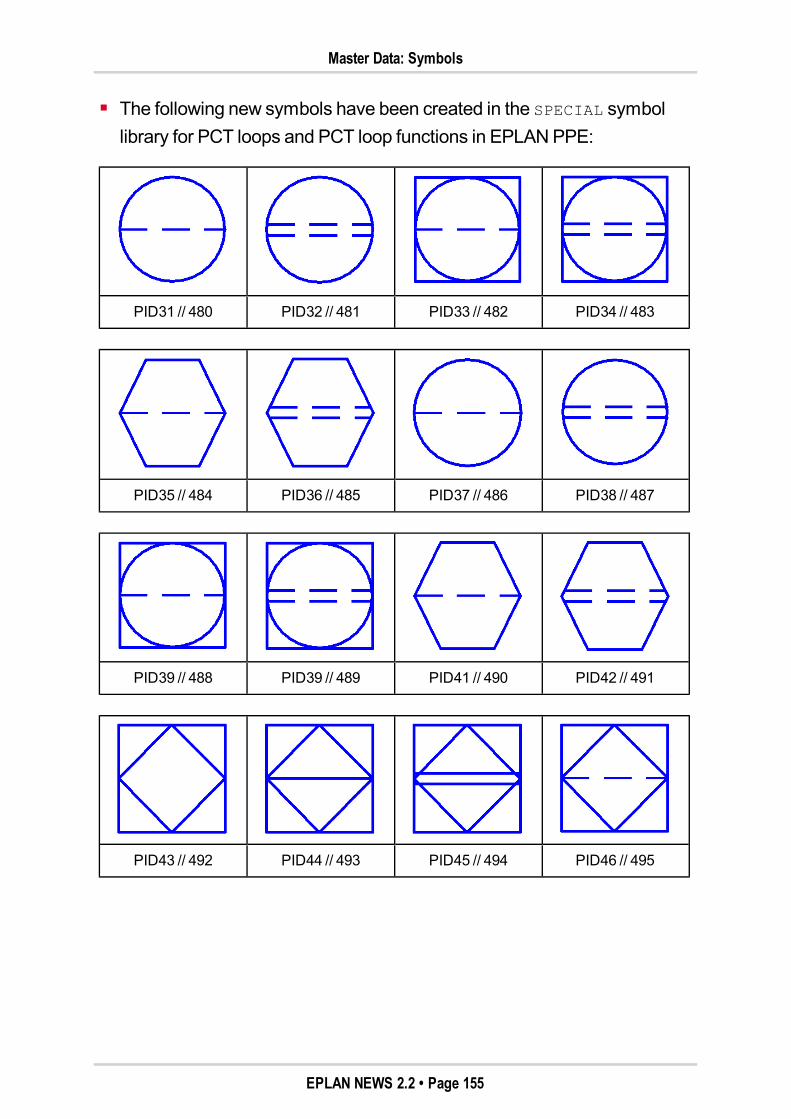
Master Data: Symbols
The following new symbols have been created in the SPECIAL symbollibrary for PCT loops and PCT loop functions in EPLANPPE:
PID31 // 480 PID32 // 481 PID33 // 482 PID34 // 483
PID35 // 484 PID36 // 485 PID37 // 486 PID38 // 487
PID39 // 488 PID39 // 489 PID41 // 490 PID42 // 491
PID43 // 492 PID44 // 493 PID45 // 494 PID46 // 495
EPLAN NEWS 2.2 • Page 155
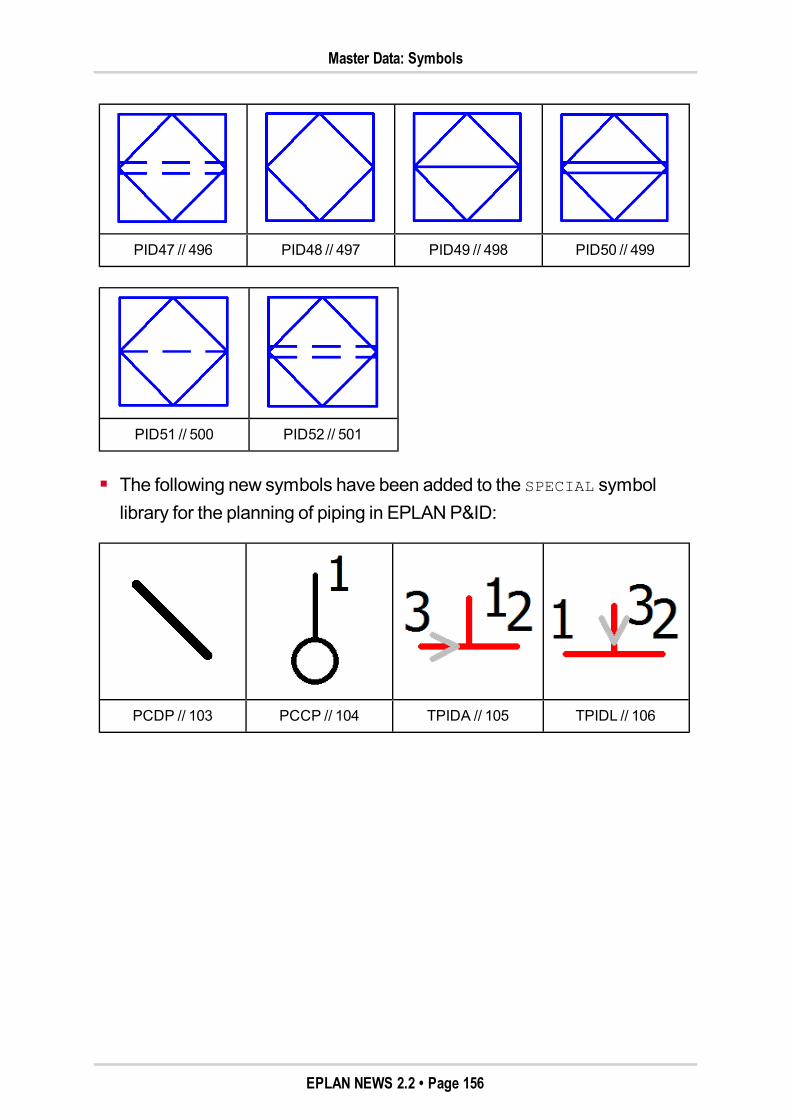
Master Data: Symbols
PID47 // 496 PID48 // 497 PID49 // 498 PID50 // 499
PID51 // 500 PID52 // 501
The following new symbols have been added to the SPECIAL symbollibrary for the planning of piping in EPLANP&ID:
PCDP // 103 PCCP // 104 TPIDA // 105 TPIDL // 106
EPLAN NEWS 2.2 • Page 156
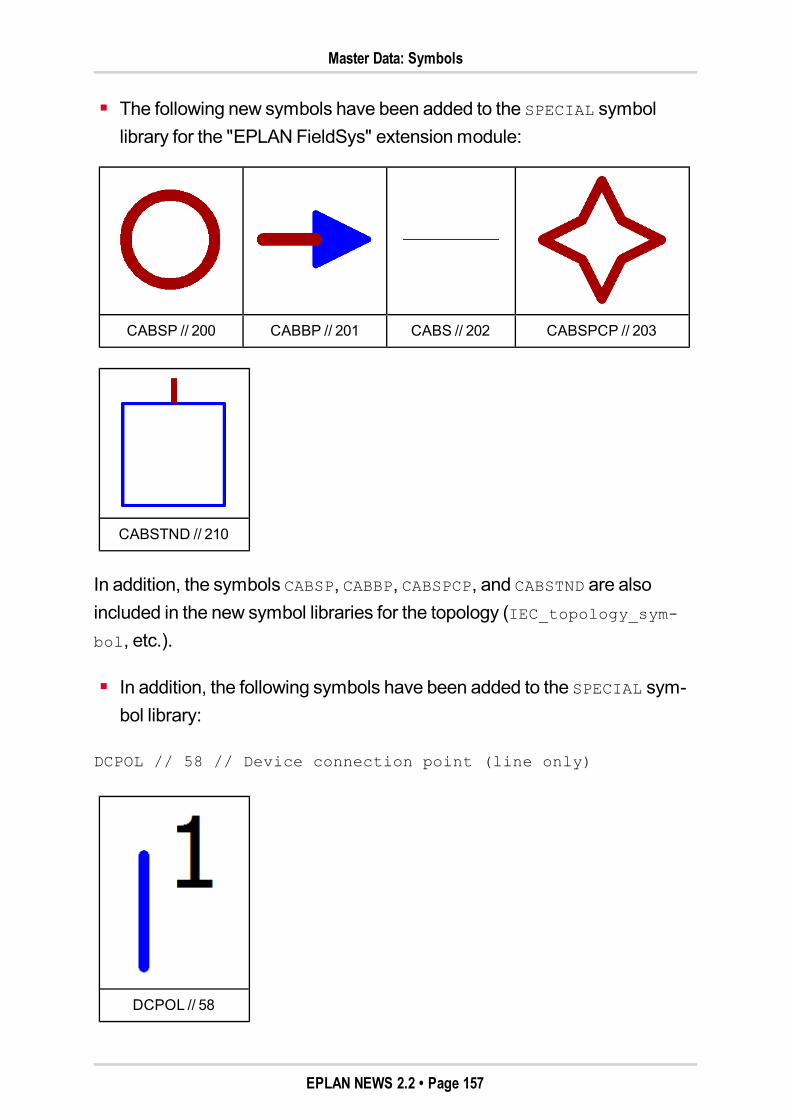
Master Data: Symbols
The following new symbols have been added to the SPECIAL symbollibrary for the "EPLANFieldSys" extensionmodule:
CABSP // 200 CABBP // 201 CABS // 202 CABSPCP // 203
CABSTND // 210
In addition, the symbols CABSP, CABBP, CABSPCP, and CABSTND are alsoincluded in the new symbol libraries for the topology (IEC_topology_sym-bol, etc.).
In addition, the following symbols have been added to the SPECIAL sym-bol library:
DCPOL // 58 // Device connection point (line only)
DCPOL // 58
EPLAN NEWS 2.2 • Page 157
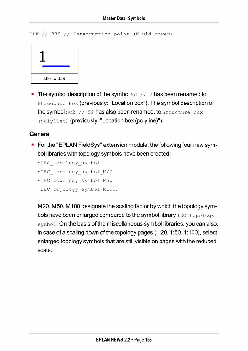
Master Data: Symbols
BPF // 339 // Interruption point (Fluid power)
BPF // 339
The symbol description of the symbol SC // 2 has been renamed toStructure box (previously: "Location box"). The symbol description ofthe symbol SC2 // 52 has also been renamed, to Structure box
(polyline) (previously: "Location box (polyline)").
General
For the "EPLANFieldSys" extensionmodule, the following four new sym-bol libraries with topology symbols have been created:- IEC_topology_symbol- IEC_topology_symbol_M20- IEC_topology_symbol_M50- IEC_topology_symbol_M100.
M20, M50, M100 designate the scaling factor by which the topology sym-bols have been enlarged compared to the symbol library IEC_topology_symbol. On the basis of themiscellaneous symbol libraries, you can also,in case of a scaling down of the topology pages (1:20, 1:50, 1:100), selectenlarged topology symbols that are still visible on pages with the reducedscale.
EPLAN NEWS 2.2 • Page 158
Master Data: Function Definition Library
Master Data: Function Definition LibrarySome new function definitions have been added to the function definitionlibrary. For further information on the properties, the basic symbol, etc. of thefunction definitions listed below in the Function definitions dialog, navigateto the location indicated in theSelection field.
Trade: General
Under General // General special functions // Topology
routing track // Topology routing path, the following new func-tion definition has been added:– Topology routing path.
Under General // General special functions // Topology
routing track // Topology routing point, the following new func-tion definition has been added:– Topology routing point.
Under General // General special functions // Connection
// Connection definition, the following new function definition hasbeen added:– Switching jumper.
Trade: Electrical engineering
Under Electrical engineering // Protection device // Motor
overload switch // Motor overload switch, 2 connection
points, the following new function definition has been added:– Motor overload switch, single-line.
Under Electrical engineering // Protection device // Motor
overload switch // Motor overload switch, 4 connection
points, the following new function definition has been added:– Motor overload switch, two-pole.
EPLAN NEWS 2.2 • Page 159
Master Data: Forms
Under Electrical engineering // Protection device // Motor
overload switch // Motor overload switch, 6 connection
points, the following new function definition has been added:– Motor overload switch, three-pole (previously: "Motor overloadswitch").
Trade: Mechanics
Under Mechanics // Design mode // Area definition //
Restricted area, the following function definitions have been renamed:– Restricted drilling area (previously: "Restricted hole area")– Restricted placing area (previously: "Restrictedmounting area")– Restricted routing area (renamed in the German version only).
Under Mechanics // Current distribution // Copper bundles
// Copper bundle, the following new function definition has beenadded:– Copper bundle.
Master Data: FormsThe following five new forms have been created:
F22_004.f22 (File type "Plug diagram")
F34_001.f34 (File type "Topology: Routing path list")
F35_001.f35 (File type "Topology: Routing path diagram")
F36_001.f36 (File type "Topology: Routed cables / connections")
F37_001.f37 (File type "Process overview"; for EPLANPPE).
Master Data: SchemesTwo new filter schemes have been created for theSymbol selection dialog:
PID_ESS
PPE_SYM.
EPLAN NEWS 2.2 • Page 160
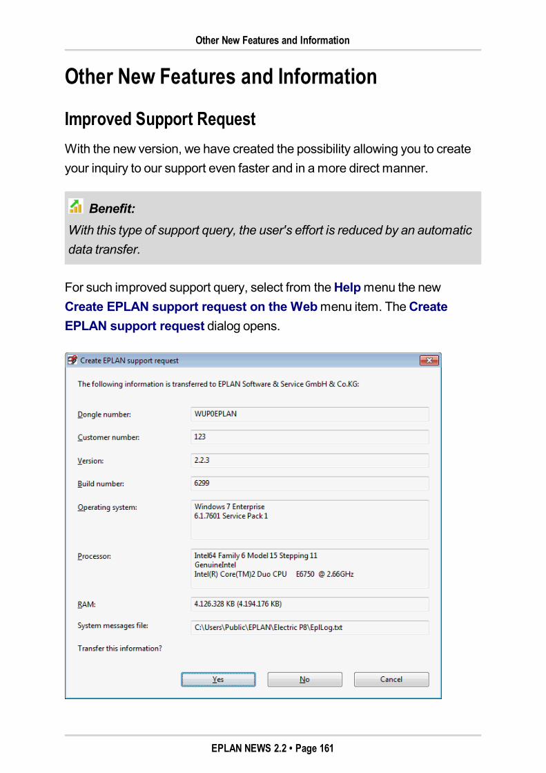
Other New Features and Information
Other New Features and Information
Improved Support RequestWith the new version, we have created the possibility allowing you to createyour inquiry to our support even faster and in amore direct manner.
Benefit:With this type of support query, the user's effort is reduced by an automaticdata transfer.
For such improved support query, select from theHelpmenu the newCreate EPLAN support request on the Webmenu item. TheCreateEPLAN support request dialog opens.
EPLAN NEWS 2.2 • Page 161
Improved Support Request
This dialog displays the information (Dongle number, Version, etc.) that istransferred to EPLAN support automatically. If you agree to this transfer ofinformation, click [Yes]. Subsequently, you will be logged into the supportarea automatically. There, you can submit your support request or view infor-mation on an existing support request.
If you do not agree to the transfer of this information and click [No], theEPLANwebsite opens, and you have to log into the support area – as before.
Note:This improved support request is available to you only if you have a validsoftware service agreement, and your customer number is stored in theEPLAN platform. For this purpose, theSettings: User code / addressdialog has been extended to included theCustomer number field. Enteryour customer number here.
EPLAN NEWS 2.2 • Page 162
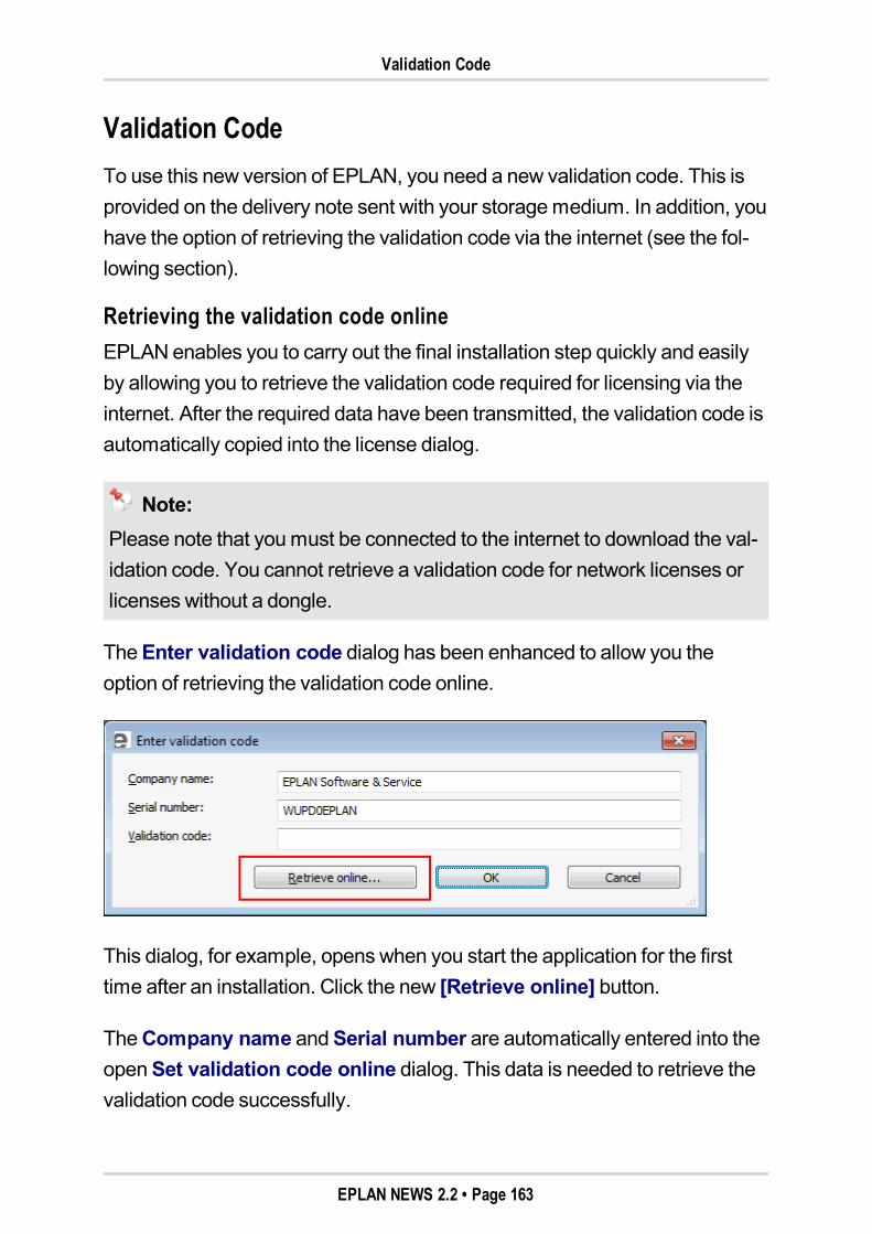
Validation Code
Validation CodeTo use this new version of EPLAN, you need a new validation code. This isprovided on the delivery note sent with your storagemedium. In addition, youhave the option of retrieving the validation code via the internet (see the fol-lowing section).
Retrieving the validation code onlineEPLAN enables you to carry out the final installation step quickly and easilyby allowing you to retrieve the validation code required for licensing via theinternet. After the required data have been transmitted, the validation code isautomatically copied into the license dialog.
Note:Please note that youmust be connected to the internet to download the val-idation code. You cannot retrieve a validation code for network licenses orlicenses without a dongle.
TheEnter validation code dialog has been enhanced to allow you theoption of retrieving the validation code online.
This dialog, for example, opens when you start the application for the firsttime after an installation. Click the new [Retrieve online] button.
TheCompany name andSerial number are automatically entered into theopenSet validation code online dialog. This data is needed to retrieve thevalidation code successfully.
EPLAN NEWS 2.2 • Page 163
Retrieving the validation code online
Up-to-date information
If you would like to receive information in the future (such as oureNewsletter), please activate the I would like to receive further infor-mation check box. EPLANwill then save your personal details (Name,Phone, E-mail address, etc.).
Internet settings
The settings for the existing internet connection are adopted by default. Youcan also use a proxy server as a network component via the [Settings] but-ton and the dialog that then opens. If this is the case, youmust enter thecorresponding information onAddress, Port, etc. Please consult with youradministrator about the settings in this area.
Returning the validation code
Click [Send] to send the encoded data to EPLAN. If your details are alreadyheld by EPLAN and are valid, a validation code is created and sent to thelicense dialog. Then start the application by clicking [OK].
EPLAN NEWS 2.2 • Page 164
Installation
InstallationStarting with version 2.1, EPLAN program variants and add-ons are installedvia the EPLANSetupManager. The basic procedure in the EPLANSetupManager has remained unchanged. For the user interface and directories,the followingmodifications have beenmade to the installation of this version:
Separate installation of the dongle driverThe installation of the dongle driver is now down independently of theinstallation of the EPLAN License Client. In the EPLANSetupManager,you specify whether you want to install the dongle driver or not. For this,you can use the new Install dongle driver check box below the [Masterdata and languages] button in connection with a user-defined instal-lation.
Notes:By default, the Install dongle driver check box is activated. For exam-ple, youmust deactivate the check box so as not to install the driveragain when installing another EPLAN program variant.
With a distributed installation (e.g., MSI installation), too, the dongledriver is no longer installed automatically. For an installation with thedongle driver, youmust make the call HASPUserSetup.exe with theparameter /passive.
During the installation, the dongle driver is stored in the directory of theEPLAN License Client. ForWindows 7, the directory for the corre-sponding file HASPUserSetup.exe could be, for example: C:\ProgramFiles (x86)\EPLAN\COMMON.
Tip:The dongle driver can be uninstalled in the Control Panel. In the uninstalldialog, select the entry "Sentinel Runtime" for this purpose.
EPLAN NEWS 2.2 • Page 165
Installation
Renamed installation packages for the master dataTo differentiate the data installation packages of the original EPLANmaster datamore clearly from the program add-ons to be installed, theinstallation packages for themaster data have been renamed. Thus, forexample, the installation package with the original EPLANmaster data ofthe EPLAN variant EPLANFluid is now called "EPLANFluid Data 2.2",while the program add-on continues to be called "Fluid Add-on".
New directory for settings databasesThe configuration directory for the settings databases generated at thetime of the installation now has a new component, the directory Win32.The CFG directory with the user, company, etc. settings is generated as asubdirectory of this new directory (e.g., for theWindows 7 operating sys-tem inWindows Explorer:C:\Users\Public\EPLAN\Electric P8\2.2.0\Win32\Cfg).
No empty directories for original EPLAN master dataThe installation of the EPLAN program variants no longer generatesemptymaster data directories in the directories for the original EPLANmaster data.
Note:For theWindows XP operating system, the default directory for the originalEPLANmaster data is, e.g., C:\Documents and Settings\All
Users\EPLAN\, and forWindows 7, the default directory isC:\ProgramData\EPLAN.
EPLAN NEWS 2.2 • Page 166
Installation of server-stored profiles
English directory names for original EPLAN master dataIn addition, the original EPLANmaster data are now copied to directorieswith English designations during the installation. This way, the originalEPLANmaster data are now found in uniform directories all over theworld.
Note:The directory names of themaster data that users work with (the systemmaster data) continue to be translated into all EPLAN user interface lan-guages. These directory names, at the time of the installation, are createdin the language that is set as the activated languagemodule in the EPLANSetupManager.
Installation of server-stored profilesFor the EPLAN platform to be used in connection with server-storedprofiles, it is now possible also to specify environment variables (e.g.,%APPDATA%) for the directories of the settings databases during the instal-lation (see the following section).
Installation of server-stored profilesServer-stored user profiles ("roaming profiles") allow users to log onto dif-ferent computers within a network domain and to work there with their usualdesktop settings.
The newEPLAN version now allows for the settings databases to be storedbelow the %APPDATA%\EPLAN directory. Such a directory is required for theuse of server-stored profiles.
EPLAN NEWS 2.2 • Page 167
Installation of server-stored profiles
To install the settings databases in such a directory, it is now permitted tospecify environment variables for the settings databases in the EPLANSetupManager during the installation. The environment variablesmay be enteredonly for the target directories of the fieldsUser settings,Workstation set-tings, andCompany settings. Ameaningful input would be, for example,%APPDATA%\EPLAN.
The %APPDATA% environment variable returns the directory path where appli-cations save data by default. During the installation, such a directory path isthen carried over to the install.xml file. The settings databases are notgenerated in the %APPDATA%\EPLAN directory until EPLAN is started. Indetail, the directory path could look like this, for example:C:\Users\<YourProfilename>\AppData\Roaming\EPLAN.
Note:For such an installation, you should be logged in as an administratorand have amore profound knowledge of the program and system.
In case of an automatic installation (e.g., via a MSI file), the directorypath is resolved by theWindows command prompt. In this case, afterthe installation, youmust modify the directories for the settings data-bases in the install.xml file to %APPDATA%. You can find theinstall.xml file in the CFG directory of the installed EPLAN programvariant.
EPLAN NEWS 2.2 • Page 168
Software Requirements and Approvals
Software Requirements and ApprovalsAll release information refers to the 32-bit version of the products, unlessstated otherwise.
General requirementsThe operation of the EPLAN platform requires .NET Framework 4.0 andMicrosoft Core XMLServices (MSXML6) 6.0 from Microsoft. Further infor-mation and the latest versions of theseMicrosoft components are availablefor download from theMicrosoft website.
You will find .NET Framework 4.0 on your EPLAN storagemedium. Switchhere to the following directory:cd-rom\Services\Net Framework 4.0\en_US
To install .NET Framework, double-click the fileDotNetFx40_Full_x86_x64.exe.
Operating systemsEPLAN recommends the use of a 64-bit Windows operating system due toimprovedmemorymanagement. The EPLAN platform has been cleared forthe following operating systems:
Workstation
Microsoft Windows XPProfessional SP3 (32 bit)
Microsoft Windows 7 SP1 (32 bit and 64 bit)Professional, Enterprise, Ultimate
Server
Microsoft Windows Server 2003 SP2 (32 bit and 64 bit)
Microsoft Windows Server 2008 SP2 (32 bit and 64 bit)
Microsoft Windows Server 2008 RC2 (64 bit)
EPLAN NEWS 2.2 • Page 169
Microsoft products
Microsoft productsMicrosoft Office 2007 (32 bit)
Microsoft Office 2010 (32 bit)
Microsoft Internet Explorer 8
Microsoft Internet Explorer 9
SQL serverMicrosoft SQL Server 2005 SP2
Microsoft SQL Server 2008 R2
Microsoft SQL-Server 2010
Autodesk productsAutoCAD 2011 (32-bit und 64-bit)
AutoCAD 2012 (32-bit und 64-bit)
Autodesk Productstream Professional 2011
Autodesk Productstream Professional 2012
Autodesk Vault 2011
Autodesk Vault 2012
Autodesk Vault 2013
PDF redliningAdobe Reader Version X
Adobe Reader Version X Standard / Pro / Pro Extended
PLC systems (PLC & bus extension)Beckhoff TwinCAT 2.10
Beckhoff TwinCAT 2.11
Phoenix Contact PCWorx 6
Rockwell RSLogix professional 20
Schneider Unity Pro 5.0
EPLAN NEWS 2.2 • Page 170
Unsupported operating systems
Schneider Unity Pro 6.0
Siemens SIMATICSTEP 7 version 5.4 SP4
Siemens SIMATICSTEP 7 version 5.5
Unsupported operating systems
Windows 2000 Professional
The EPLAN platform no longer supports theWindows 2000 Professionaloperating system that is no longer supported byMicrosoft.
Windows 2000 Server
The EPLAN platform no longer supports theWindows 2000 Server operatingsystem that is no longer supported byMicrosoft. Microsoft has ceased officialsupport for this operating system.
Windows Vista / Windows XP
Beginning with EPLAN version 2.2, theWindows Vista operating system isno longer supported. Support for Windows XPwill be terminated with thenext version of the EPLAN platform. From 2013, the EPLAN platform onlysupports the 64-bit variant of theMicrosoft operating systemsWindows 7andWindows 8.
Note:Further information on the life cycle of operating systems is available ontheMicrosoft website.
EPLAN NEWS 2.2 • Page 171

EPLAN software no longer supported
EPLAN software no longer supported
EPLAN License Manager (32-bit version)
Weare offering a new 64-bit version of our EPLAN LicenseManager for themanagement of network licenses alongside the newEPLAN platform. Forthis reason, the 32-bit versions of the EPLAN LicenseManager (versions 6.1and 7.1) will not be supported anymore in the next version of the EPLAN plat-form.
EPLAN Schematic Generator
A transparent automatization strategy for tomorrow's requirements has beenrealized with our new product, EPLANEngineering Center One (EECOne).EECOne extends our solution portfolio as a key link between conventionalandmechatronic engineering. As part of this new product, the EPLANSche-matic Generator is replaced by the EECOne. Maintenance for the EPLANSchematic Generator will be continued until September 2013.
EPLAN NEWS 2.2 • Page 172