Embed Size (px)
Citation preview
Newly started software EM project:Antenna Toolbox for MATLAB
7th COST VISTA meeting in Madrid
Miloslav Capek1 Pavel Hazdra1 Milos Mazanek1
Zbynek Raida2 et al.
1Department of Electromagnetic FieldCTU in Prague, Czech [email protected]
2Department of Radio ElectronicsBUT, Czech Republic
October 23, 2014
Capek, Hazdra, Mazanek, Raida, et al. AToM: Antenna Toolbox For Matlab 1 / 24
1 Introduction
2 Source Concept
What is the source concept?
Selected applications of the source concept
Requirements
3 Design of optimal antennas
4 About AToM
Introduction
5 AToM’s Architecture
AToM’s – Contemporary Techniques
AToM’s – Scheduled Features
6 Integration into Visual CEM (ESI Group)
Capek, Hazdra, Mazanek, Raida, et al. AToM: Antenna Toolbox For Matlab 2 / 24
Introduction
Newly started software EM project
Motivation = to describe newly started project on antenna design
I up-to-date requirements of modern antenna design will besummarized
• source concept
I as a consequence, new project will be introduced
• AToM (Antenna Toolbox For Matlab)• AToM = transition from scientific code to the commercial toolbox
I project’s details will be presented
• AToM’s features
Capek, Hazdra, Mazanek, Raida, et al. AToM: Antenna Toolbox For Matlab 3 / 24
Source Concept What is the source concept?
Source ConceptWhat is actually the Source Concept?
Source Concept
Integral andvariationalmethods
Modalmethods
Perspectivetopol-
ogy andgeometry
HPC,algorithmefficiency
Heuristicor convex
optimization
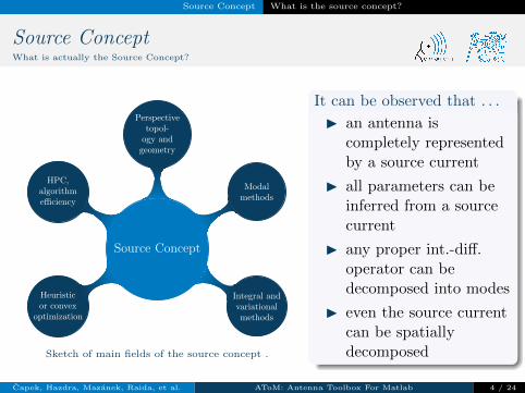
Sketch of main fields of the source concept .
It can be observed that . . .
I an antenna iscompletely representedby a source current
I all parameters can beinferred from a sourcecurrent
I any proper int.-diff.operator can bedecomposed into modes
I even the source currentcan be spatiallydecomposed
Capek, Hazdra, Mazanek, Raida, et al. AToM: Antenna Toolbox For Matlab 4 / 24
Source Concept Selected applications of the source concept
Source ConceptApplications: Characteristic Modes
W
J1
W
J2
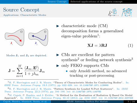
Modes J1 and J2 are depicted.
J =
M∑m=1
〈Jm,Ei〉
1 + λmJm
I characteristic mode (CM)decomposition forms a generalizedeigen-value problem1:
XJ = λRJ (1)
I CMs are excellent for patternsynthesis2 or feeding network synthesis3
I only FEKO supports CMs
• only Arnoldi method, no advancedtracking or post-processing
1R. F. Harrington and J. R. Mautz. “Theory of Characteristic Modes for Conducting Bodies”. In:IEEE Trans. Antennas Propag. 19.5 (1971), pp. 622–628. doi: 10.1109/TAP.1971.1139999
2R. F. Harrington and J. R. Mautz. “Pattern Synthesis for Loaded N-Port Scatterers”. In: IEEETrans. Antennas Propag. 22.2 (1974), pp. 184–190. doi: 10.1109/TAP.1974.1140785
3M. Capek, P. Hazdra, and J. Eichler. “A Method for the Evaluation of Radiation Q Based On ModalApproach”. In: IEEE Trans. Antennas Propag. 60.10 (2012), pp. 4556–4567. doi: 10.1109/TAP.2012.2207329
Capek, Hazdra, Mazanek, Raida, et al. AToM: Antenna Toolbox For Matlab 5 / 24
Source Concept Selected applications of the source concept
Source ConceptApplications: Structural Decomposition
W2W1
J(rA) J(rB)
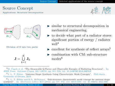
Division of Ω into two parts.
J =K⋃k=1
Jk
I similar to structural decomposition inmechanical engineering
I to decide what part of a radiator storessignificant portion of energy / radiateswell4
I excellent for synthesis of reflect arrays5
I combination with CM: sub-structuremodes6
4M. Capek et al. “The Measurable Q Factor and Observable Energies of Radiating Structures”. In:IEEE Trans. Antennas Propag. 62.1 (2014), pp. 311–318. doi: 10.1109/TAP.2013.2287519
5J. L. T. Ethier. “Antenna Shape Synthesis Using Characteristic Mode Concepts”. PhD thesis.University of Ottawa, 2012
6J. L. T. Ethier and D.A. McNamara. “Sub-structure characteristic mode concept for antenna shapesynthesis”. In: Electronics Letters 48.9 (2012), pp. 471–472. issn: 0013-5194. doi: 10.1049/el.2012.0392
Capek, Hazdra, Mazanek, Raida, et al. AToM: Antenna Toolbox For Matlab 6 / 24
Source Concept Selected applications of the source concept
Source ConceptApplications: Optimization
W0
Wmax
Wfinal
Wmax
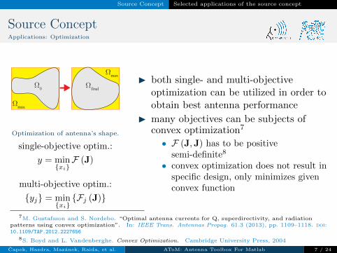
Optimization of antenna’s shape.
single-objective optim.:
y = minxiF (J)
multi-objective optim.:
yj = minxiFj (J)
I both single- and multi-objectiveoptimization can be utilized in order toobtain best antenna performance
I many objectives can be subjects ofconvex optimization7
• F (J,J) has to be positivesemi-definite8
• convex optimization does not result inspecific design, only minimizes givenconvex function
7M. Gustafsson and S. Nordebo. “Optimal antenna currents for Q, superdirectivity, and radiationpatterns using convex optimization”. In: IEEE Trans. Antennas Propag. 61.3 (2013), pp. 1109–1118. doi:10.1109/TAP.2012.2227656
8S. Boyd and L. Vandenberghe. Convex Optimization. Cambridge University Press, 2004
Capek, Hazdra, Mazanek, Raida, et al. AToM: Antenna Toolbox For Matlab 7 / 24
Source Concept Selected applications of the source concept
Source ConceptApplications: Advanced Post-processing
VG1
VG2A VG2B
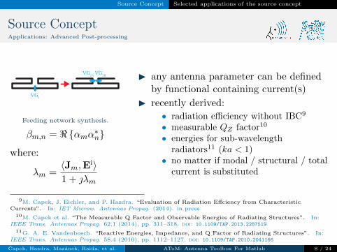
Feeding network synthesis.
βm,n = <αmα∗n
where:
λm =〈Jm,E
i〉1 + λm
I any antenna parameter can be definedby functional containing current(s)
I recently derived:
• radiation efficiency without IBC9
• measurable QZ factor10
• energies for sub-wavelengthradiators11 (ka < 1)
• no matter if modal / structural / totalcurrent is substituted
9M. Capek, J. Eichler, and P. Hazdra. “Evaluation of Radiation Effciency from CharacteristicCurrents”. In: IET Microw. Antennas Propag. (2014). in press
10M. Capek et al. “The Measurable Q Factor and Observable Energies of Radiating Structures”. In:IEEE Trans. Antennas Propag. 62.1 (2014), pp. 311–318. doi: 10.1109/TAP.2013.2287519
11G. A. E. Vandenbosch. “Reactive Energies, Impedance, and Q Factor of Radiating Structures”. In:IEEE Trans. Antennas Propag. 58.4 (2010), pp. 1112–1127. doi: 10.1109/TAP.2010.2041166
Capek, Hazdra, Mazanek, Raida, et al. AToM: Antenna Toolbox For Matlab 8 / 24
Source Concept Requirements
Source ConceptRequirements: Fast-prototyping Environment
MathWorks MATLAB logo.
I up to now, there is no commercialpackage that completely implementstechniques mentioned above
I scientists develop and utilize their owncodes
• codes are mainly written in Matlab12
• Matlab is high-definition language forfast-prototyping
• many built-in functions are embedded• new functionality can easily be
published13
• Matlab is remarkably cheaper thanany multi-physical EM software
12The MathWorks. The Matlab. url: www.mathworks.com
13www.mathworks.com/matlabcentral/fileexchange
Capek, Hazdra, Mazanek, Raida, et al. AToM: Antenna Toolbox For Matlab 9 / 24
Source Concept Requirements
Source ConceptRequirements: Computational Resources
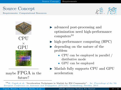
CPU×
GPU
maybe FPGA in thefuture?
I advanced post-processing andoptimization need high-performancecomputers14
I high-performance computing (HPC)
I depending on the nature of theproblem
• CPU can be employed in parallel /distibutive mode
• GPU can be employed
I Matlab fully supports CPU and GPUacceleration
14M. Capek et al. “Acceleration Techniques in Matlab for EM Community”. In: Proceedings of the 7thEuropean Conference on Antennas and Propagation (EUCAP). Gothenburg, Sweden, 2013
Capek, Hazdra, Mazanek, Raida, et al. AToM: Antenna Toolbox For Matlab 10 / 24
Design of optimal antennas
Design of optimal antenna
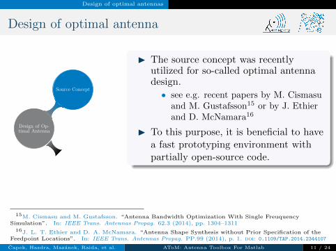
Source Concept
Design of Op-timal Antenna
AntennaSynthesis
AToM
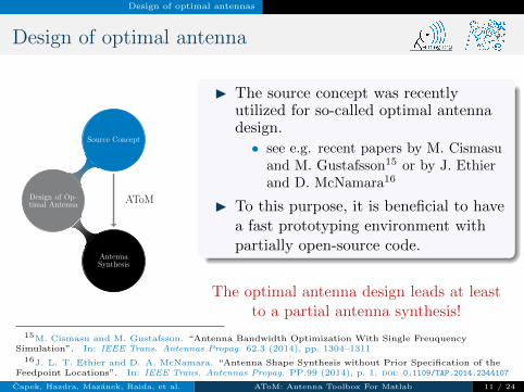
I The source concept was recentlyutilized for so-called optimal antennadesign.
• see e.g. recent papers by M. Cismasuand M. Gustafsson15 or by J. Ethierand D. McNamara16
I To this purpose, it is beneficial to havea fast prototyping environment withpartially open-source code.
The optimal antenna design leads at leastto a partial antenna synthesis!
15M. Cismasu and M. Gustafsson. “Antenna Bandwidth Optimization With Single FreuquencySimulation”. In: IEEE Trans. Antennas Propag. 62.3 (2014), pp. 1304–1311
16J. L. T. Ethier and D. A. McNamara. “Antenna Shape Synthesis without Prior Specification of theFeedpoint Locations”. In: IEEE Trans. Antennas Propag. PP.99 (2014), p. 1. doi: 0.1109/TAP.2014.2344107
Capek, Hazdra, Mazanek, Raida, et al. AToM: Antenna Toolbox For Matlab 11 / 24
Design of optimal antennas
Design of optimal antenna
Source Concept
Design of Op-timal Antenna
AntennaSynthesis
AToM
I The source concept was recentlyutilized for so-called optimal antennadesign.
• see e.g. recent papers by M. Cismasuand M. Gustafsson15 or by J. Ethierand D. McNamara16
I To this purpose, it is beneficial to havea fast prototyping environment withpartially open-source code.
The optimal antenna design leads at leastto a partial antenna synthesis!
15M. Cismasu and M. Gustafsson. “Antenna Bandwidth Optimization With Single FreuquencySimulation”. In: IEEE Trans. Antennas Propag. 62.3 (2014), pp. 1304–1311
16J. L. T. Ethier and D. A. McNamara. “Antenna Shape Synthesis without Prior Specification of theFeedpoint Locations”. In: IEEE Trans. Antennas Propag. PP.99 (2014), p. 1. doi: 0.1109/TAP.2014.2344107
Capek, Hazdra, Mazanek, Raida, et al. AToM: Antenna Toolbox For Matlab 11 / 24
About AToM Introduction
AToM: Antenna Toolbox For Matlab,,Antenna source concept” – New approach to antenna design.
New EM project AToM (Antenna Toolbox For Matlab)started from September 2014.
Logo of the AToM project.
The main idea behind the AToM toolbox isto develop new package that will be able to:
I utilize the source concept features
I handle with data from third partysoftware
I accept other codes from the community
I make it possible the fast-prototyping ofadvanced antenna designs
Capek, Hazdra, Mazanek, Raida, et al. AToM: Antenna Toolbox For Matlab 12 / 24
About AToM Introduction
Project Details #1
I web: antennatoolbox.com , antennatoolbox.eu
• under construction!!• fully operational in 3-4 weeks
I 3 participants
• CTU in Prague (COST VISTA member, project grant holder)• BUT (COST VISTA member)• MECAS ESI (subsidiary of ESI Group)
I project’s staff
• Miloslav Capek, Pavel Hazdra, Milos Mazanek, Viktor Adler, VitLosenicky, Ondrej Kratky
• Jaroslav Rymus, Vaclav Kleisner et al.• Zbynek Raida, Petr Kadlec, Vladimir Sedenka, Jan Puskely, Martin
Marek, Lukas Pospisil
Capek, Hazdra, Mazanek, Raida, et al. AToM: Antenna Toolbox For Matlab 13 / 24
AToM’s Architecture
Project Details #2
I application to become Matlab Pre-product Partner submitted
I partially open-source code
• key parts will be compiled (.p-code or .mex)• new functionality can easily be added by the users• detailed documentation of all features
I data storage: HDF5 + Amelet
• e.g. EDX has no accessible documentation
I support of Technology Agency of the Czech Republic
• 07/2014 – 12/2017• approx. 600 ke
α−projects logo of Technology Agency of Czech Republic.
Capek, Hazdra, Mazanek, Raida, et al. AToM: Antenna Toolbox For Matlab 14 / 24
AToM’s Architecture
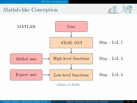
Matlab-like Conception
User
AToM: GUI
High-level functions
Low-level functions
Skilled user
Expert user
MATLAB
Map – LvL 1
Map – LvL 2
Map – LvL 3
Scheme of AToM.
Capek, Hazdra, Mazanek, Raida, et al. AToM: Antenna Toolbox For Matlab 15 / 24
AToM’s Architecture
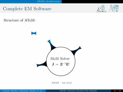
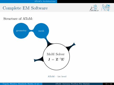
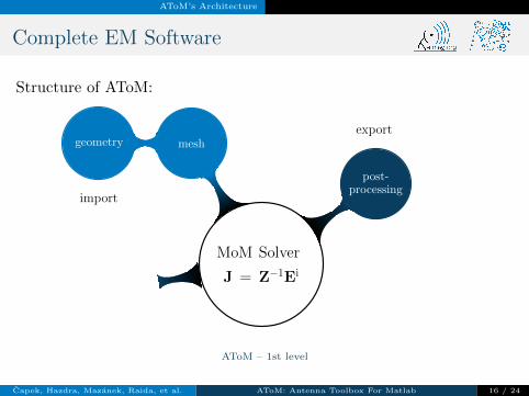
Complete EM Software
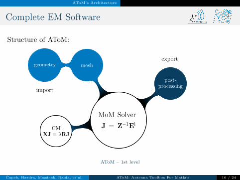
Structure of AToM:
MoM Solver
J = Z−1Ei
meshgeometry
post-processing
CMXJ = λRJ
import
export
AToM – 1st level
Capek, Hazdra, Mazanek, Raida, et al. AToM: Antenna Toolbox For Matlab 16 / 24
AToM’s Architecture
Complete EM Software
Structure of AToM:
MoM Solver
J = Z−1Ei
meshgeometry
post-processing
CMXJ = λRJ
import
export
AToM – 1st level
Capek, Hazdra, Mazanek, Raida, et al. AToM: Antenna Toolbox For Matlab 16 / 24
AToM’s Architecture
Complete EM Software
Structure of AToM:
MoM Solver
J = Z−1Ei
meshgeometry
post-processing
CMXJ = λRJ
import
export
AToM – 1st level
Capek, Hazdra, Mazanek, Raida, et al. AToM: Antenna Toolbox For Matlab 16 / 24
AToM’s Architecture
Complete EM Software
Structure of AToM:
MoM Solver
J = Z−1Ei
meshgeometry
post-processing
CMXJ = λRJ
import
export
AToM – 1st level
Capek, Hazdra, Mazanek, Raida, et al. AToM: Antenna Toolbox For Matlab 16 / 24
AToM’s Architecture AToM’s – Contemporary Techniques
Contemporary Techniques #1
0.5 1 1.5 2 2.5 3 3.5
−20
−10
0
10
20
ka
λ
OoP mode (dipoles)IP mode (dipoles)1st mode (loop)static mode (loop)
inductive behaviour
capacitivebehaviour
resonance
+-+
-
+ - -+-+
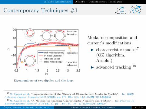
Eigennumbers of two dipoles and the loop.
Modal decomposition andcurrent’s modifications
I characteristic modes17
(QZ algorithm,Arnoldi)
I advanced tracking 18
17M. Capek et al. “Implementation of the Theory of Characteristic Modes in Matlab”. In: IEEEAntennas Propag. Magazine 55.2 (2013), pp. 176–189. doi: 10.1109/MAP.2013.6529342
18M. Capek et al. “A Method for Tracking Characteristic Numbers and Vectors”. In: Progress InElectromagnetics Research B 33 (2011), pp. 115–134. doi: 10.2528/PIERB11060209
Capek, Hazdra, Mazanek, Raida, et al. AToM: Antenna Toolbox For Matlab 17 / 24
AToM’s Architecture AToM’s – Contemporary Techniques
Contemporary Techniques #2
0.5 1 1.5 2 2.5 3 3.50
5
10
15
ka
Q Z
loop − mode0 (static)loop − mode1
dipoles (IP)dipoles (OoP, Ñ×J¹0)dipoles (OoP, Ñ×Jº0)
two dipoles
a loop
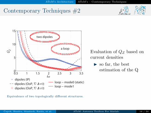
Equivalence of two topologically different structures.
Evaluation of QZ based oncurrent densities
I so far, the bestestimation of the Q
Capek, Hazdra, Mazanek, Raida, et al. AToM: Antenna Toolbox For Matlab 18 / 24
AToM’s Architecture AToM’s – Contemporary Techniques
Contemporary Techniques #3
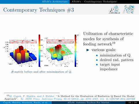
β matrix before and after minimization of Q.
Utilization of characteristicmodes for synthesis offeeding network19
I various goals:
• minimization of Q• desired rad. pattern• target input
impedance
19M. Capek, P. Hazdra, and J. Eichler. “A Method for the Evaluation of Radiation Q Based On ModalApproach”. In: IEEE Trans. Antennas Propag. 60.10 (2012), pp. 4556–4567. doi: 10.1109/TAP.2012.2207329
Capek, Hazdra, Mazanek, Raida, et al. AToM: Antenna Toolbox For Matlab 19 / 24
AToM’s Architecture AToM’s – Contemporary Techniques
Contemporary Techniques #4
0 1 2 3 4 5 6 7 8 9 100
0.2
0.4
0.6
0.8
1
σ = 5.85 105
PEC
f [GHz]
η
.
8.5
43.5
26.5
1.5
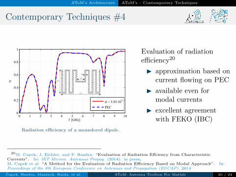
Radiation efficiency of a meandered dipole.
Evaluation of radiationefficiency20
I approximation based oncurrent flowing on PEC
I available even formodal currents
I excellent agreementwith FEKO (IBC)
20M. Capek, J. Eichler, and P. Hazdra. “Evaluation of Radiation Effciency from CharacteristicCurrents”. In: IET Microw. Antennas Propag. (2014). in press,M. Capek et al. “A Method for the Evaluation of Radiation Efficiency Based on Modal Approach”. In:Proceedings of the 8th European Conference on Antennas and Propagation (EUCAP). 2014
Capek, Hazdra, Mazanek, Raida, et al. AToM: Antenna Toolbox For Matlab 20 / 24
AToM’s Architecture AToM’s – Scheduled Features
Scheduled Features
0.6 0.8 1 1.2 1.40
20
40
60
ka
QZ
AR: QZ(4)
ME: QZ(4)/10
AR+ME: QZ(4)
QZ (Zin)
radiationfrom arms
(AR)
radiation frommeanders
(ME)
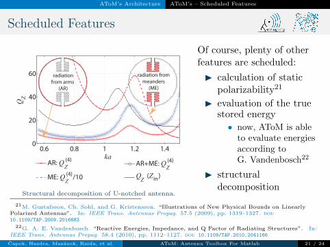
Structural decomposition of U-notched antenna.
Of course, plenty of otherfeatures are scheduled:
I calculation of staticpolarizability21
I evaluation of the truestored energy
• now, AToM is ableto evaluate energiesaccording toG. Vandenbosch22
I structuraldecomposition
21M. Gustafsson, Ch. Sohl, and G. Kristensson. “Illustrations of New Physical Bounds on LinearlyPolarized Antennas”. In: IEEE Trans. Antennas Propag. 57.5 (2009), pp. 1319–1327. doi:10.1109/TAP.2009.2016683
22G. A. E. Vandenbosch. “Reactive Energies, Impedance, and Q Factor of Radiating Structures”. In:IEEE Trans. Antennas Propag. 58.4 (2010), pp. 1112–1127. doi: 10.1109/TAP.2010.2041166
Capek, Hazdra, Mazanek, Raida, et al. AToM: Antenna Toolbox For Matlab 21 / 24
Integration into Visual CEM (ESI Group)
AToM → Visual Antenna
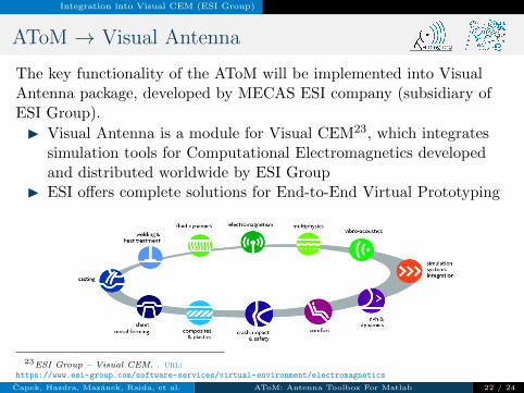
The key functionality of the AToM will be implemented into VisualAntenna package, developed by MECAS ESI company (subsidiary ofESI Group).
I Visual Antenna is a module for Visual CEM23, which integratessimulation tools for Computational Electromagnetics developedand distributed worldwide by ESI Group
I ESI offers complete solutions for End-to-End Virtual Prototyping
23ESI Group – Visual CEM. . url:https://www.esi-group.com/software-services/virtual-environment/electromagnetics
Capek, Hazdra, Mazanek, Raida, et al. AToM: Antenna Toolbox For Matlab 22 / 24
Integration into Visual CEM (ESI Group)
ESI Group and MECAS ESI
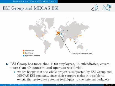
Headquarters
Subsidiaries
Agents and Distibutors Czech Republic (MECAS ESI Ltd.)
I ESI Group has more than 1000 employees, 15 subsidiaries, coversmore than 40 countries and operates worldwide• we are happy that the whole project is supported by ESI Group and
MECAS ESI company, since their support makes it possible toextent the up-to-date antenna techniques to the antenna designers
Capek, Hazdra, Mazanek, Raida, et al. AToM: Antenna Toolbox For Matlab 23 / 24
Thank you!For complete PDF presentation see capek.elmag.org
Capek, Hazdra, Mazanek, Raida, et al. AToM: Antenna Toolbox For Matlab 24 / 24