Embed Size (px)
Citation preview
New way how to use an oscilloscope
Jiří Janošík
ROHDE & SCHWARZ-Praha, s.r.o.
Holandská 878/2, Brno
Tel.: +420 725 776 778
Email: [email protected]
August 2015 | New way how to use an oscilloscope | 2
Agenda
Instrument
l Rohde & Schwarz - Introduction
l Oscilloscope portfolio
l Products Description
l High definition option - 16bit resolution
l Live demonstration
l FFT on the RTO/RTE

August 2015 | New way how to use an oscilloscope | 3
The company group at a glance
ı History Established 1933 in Munich, Germany
ı Type of enterprise Independent family-owned company
ı Global presence In over 70 countries, approx. 60 subsidiaries
ı Net revenue Approx. EUR 1.75 billion (FY 13/14, July through June)
ı Export share More than 90 percent
ı Employees 9800 worldwide, with approx. 700 in the Czech republic - Vimperk
ı Success A leading international supplier in all of its fields of business
August 2015 | New way how to use an oscilloscope | 4
Our customers
ı Wireless communication industry for voice and data
applications (suppliers of RF chip sets, modules,
systems and mobile handsets)
ı Wireless communication network element suppliers and
operators
ı Aerospace & defense wireless application suppliers
ı Service centers
ı Automotive industry
ı Test houses
ı Research (such as universities)
August 2015 | New way how to use an oscilloscope | 5
Our product groups
ı Mobile radio measurements (voice and data)
ı All-purpose RF and microwave measurements
(for example signal generation & analysis)
ı Oscilloscopes
ı Audio measurements
ı EMC measurements
ı Automated test systems and turn-key solutions
August 2015 | New way how to use an oscilloscope | 6
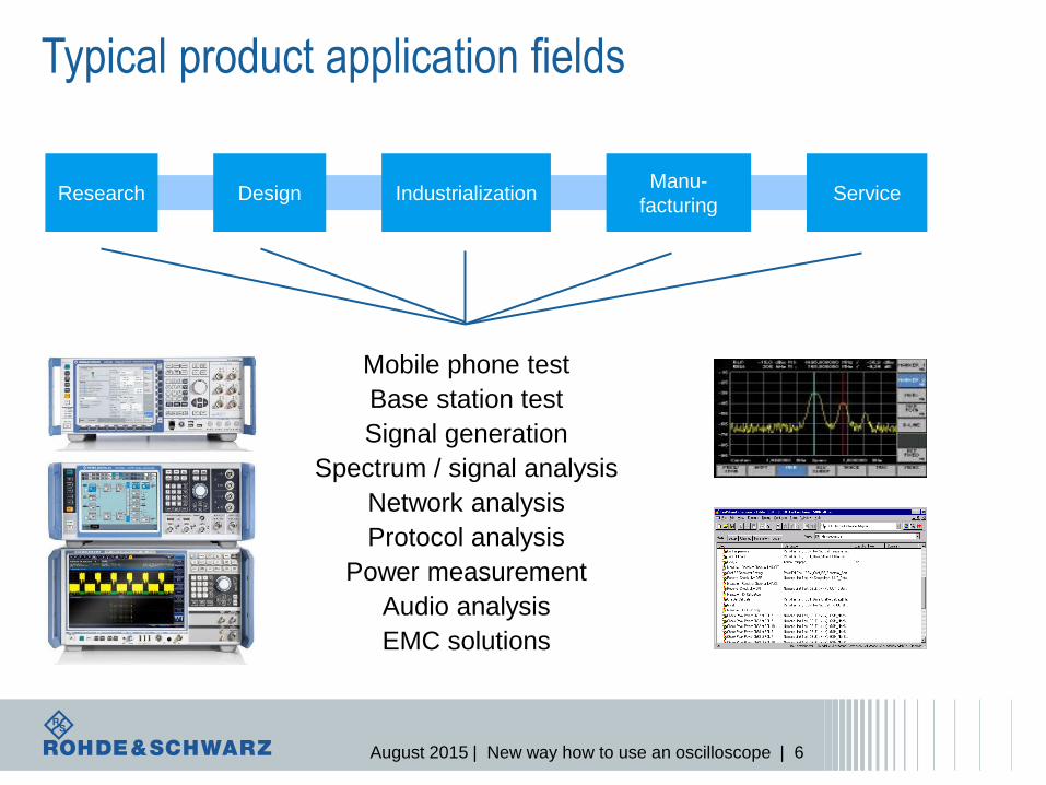
Mobile phone test
Base station test
Signal generation
Spectrum / signal analysis
Network analysis
Protocol analysis
Power measurement
Audio analysis
EMC solutions
Design Industrialization Manu-
facturing Service Research
Typical product application fields
August 2015 | New way how to use an oscilloscope | 7
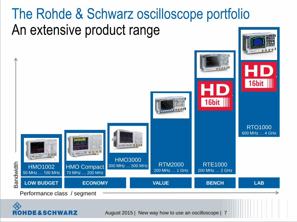
The Rohde & Schwarz oscilloscope portfolio An extensive product range
LOW BUDGET
HMO1002 50 MHz … 100 MHz
Performance class / segment
Ba
nd
wid
th
ECONOMY
HMO Compact 70 MHz … 200 MHz
HMO3000 300 MHz … 500 MHz
VALUE
RTM2000 200 MHz … 1 GHz
BENCH
RTE1000 200 MHz … 2 GHz
LAB
RTO1000 600 MHz … 4 GHz
August 2015 | New way how to use an oscilloscope | 9
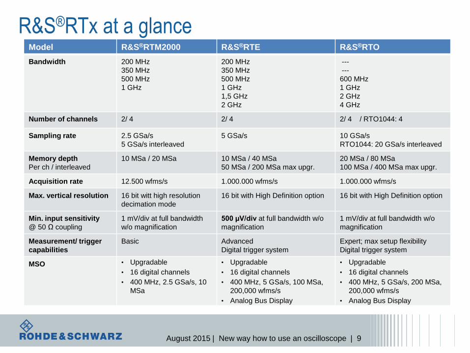
R&S®RTx at a glance
Instrument
Model R&S®RTM2000 R&S®RTE R&S®RTO
Bandwidth 200 MHz
350 MHz
500 MHz
1 GHz
200 MHz
350 MHz
500 MHz
1 GHz
1,5 GHz
2 GHz
---
---
600 MHz
1 GHz
2 GHz
4 GHz
Number of channels 2/ 4 2/ 4 2/ 4 / RTO1044: 4
Sampling rate 2.5 GSa/s
5 GSa/s interleaved
5 GSa/s 10 GSa/s
RTO1044: 20 GSa/s interleaved
Memory depth
Per ch / interleaved
10 MSa / 20 MSa 10 MSa / 40 MSa
50 MSa / 200 MSa max upgr.
20 MSa / 80 MSa
100 MSa / 400 MSa max upgr.
Acquisition rate 12.500 wfms/s 1.000.000 wfms/s 1.000.000 wfms/s
Max. vertical resolution 16 bit witt high resolution
decimation mode
16 bit with High Definition option 16 bit with High Definition option
Min. input sensitivity
@ 50 Ω coupling
1 mV/div at full bandwidth
w/o magnification
500 µV/div at full bandwidth w/o
magnification
1 mV/div at full bandwidth w/o
magnification
Measurement/ trigger
capabilities
Basic Advanced
Digital trigger system
Expert; max setup flexibility
Digital trigger system
MSO • Upgradable
• 16 digital channels
• 400 MHz, 2.5 GSa/s, 10
MSa
• Upgradable
• 16 digital channels
• 400 MHz, 5 GSa/s, 100 MSa,
200,000 wfms/s
• Analog Bus Display
• Upgradable
• 16 digital channels
• 400 MHz, 5 GSa/s, 200 MSa,
200,000 wfms/s
• Analog Bus Display
August 2015 | New way how to use an oscilloscope | 10
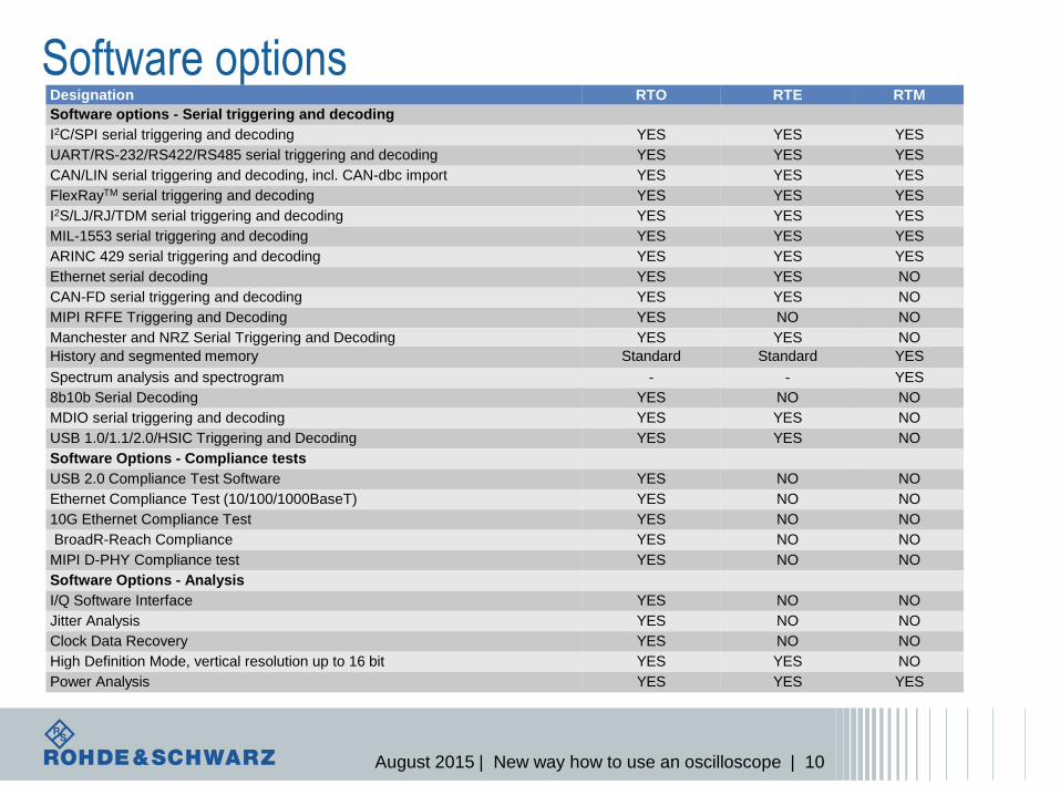
Designation RTO RTE RTM
Software options - Serial triggering and decoding
I2C/SPI serial triggering and decoding YES YES YES
UART/RS-232/RS422/RS485 serial triggering and decoding YES YES YES
CAN/LIN serial triggering and decoding, incl. CAN-dbc import YES YES YES
FlexRayTM serial triggering and decoding YES YES YES
I2S/LJ/RJ/TDM serial triggering and decoding YES YES YES
MIL-1553 serial triggering and decoding YES YES YES
ARINC 429 serial triggering and decoding YES YES YES
Ethernet serial decoding YES YES NO
CAN-FD serial triggering and decoding YES YES NO
MIPI RFFE Triggering and Decoding YES NO NO
Manchester and NRZ Serial Triggering and Decoding YES YES NO
History and segmented memory Standard Standard YES
Spectrum analysis and spectrogram - - YES
8b10b Serial Decoding YES NO NO
MDIO serial triggering and decoding YES YES NO
USB 1.0/1.1/2.0/HSIC Triggering and Decoding YES YES NO
Software Options - Compliance tests
USB 2.0 Compliance Test Software YES NO NO
Ethernet Compliance Test (10/100/1000BaseT) YES NO NO
10G Ethernet Compliance Test YES NO NO
BroadR-Reach Compliance YES NO NO
MIPI D-PHY Compliance test YES NO NO
Software Options - Analysis
I/Q Software Interface YES NO NO
Jitter Analysis YES NO NO
Clock Data Recovery YES NO NO
High Definition Mode, vertical resolution up to 16 bit YES YES NO
Power Analysis YES YES YES
Software options
August 2015 | New way how to use an oscilloscope | 11
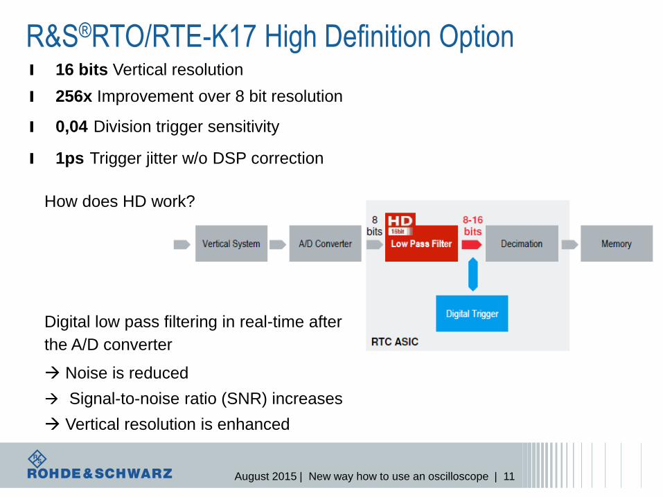
R&S®RTO/RTE-K17 High Definition Option
How does HD work?
Digital low pass filtering in real-time after
the A/D converter
Noise is reduced
Signal-to-noise ratio (SNR) increases
Vertical resolution is enhanced
l 16 bits Vertical resolution
l 256x Improvement over 8 bit resolution
l 0,04 Division trigger sensitivity
l 1ps Trigger jitter w/o DSP correction
August 2015 | New way how to use an oscilloscope | 12
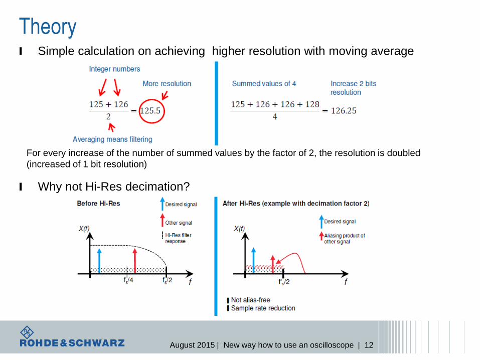
Theory l Simple calculation on achieving higher resolution with moving average
l Why not Hi-Res decimation?
For every increase of the number of summed values by the factor of 2, the resolution is doubled
(increased of 1 bit resolution)
August 2015 | New way how to use an oscilloscope | 13
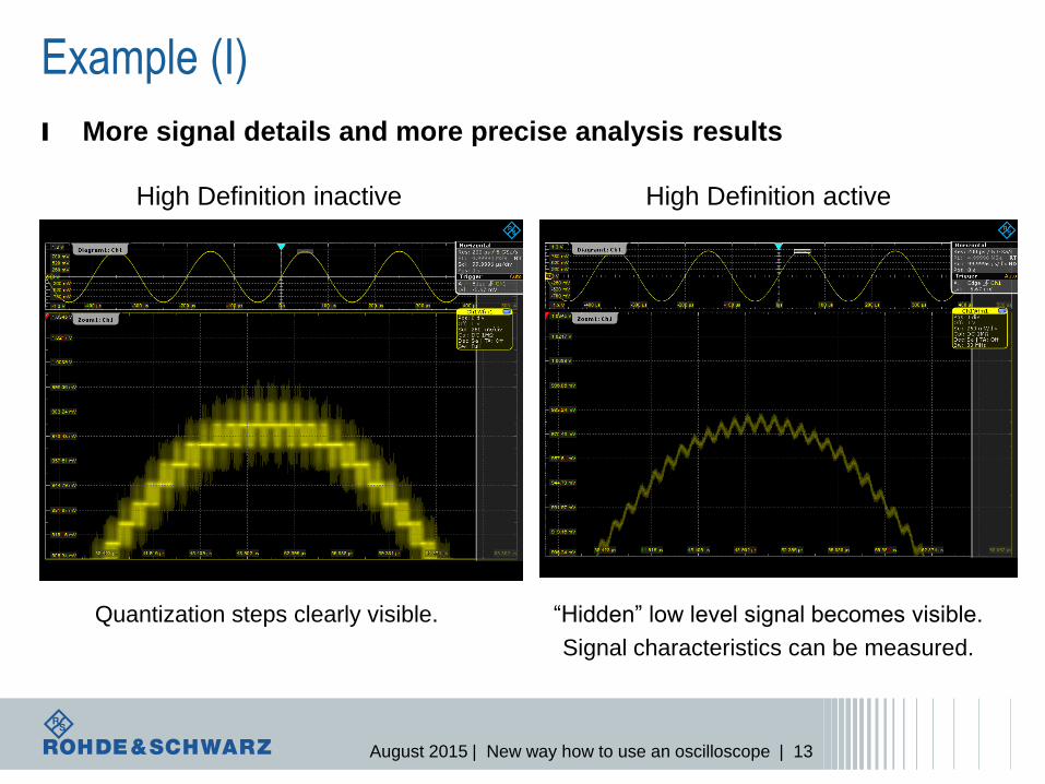
Example (I)
High Definition inactive High Definition active
Quantization steps clearly visible. “Hidden” low level signal becomes visible.
Signal characteristics can be measured.
l More signal details and more precise analysis results
August 2015 | New way how to use an oscilloscope | 14
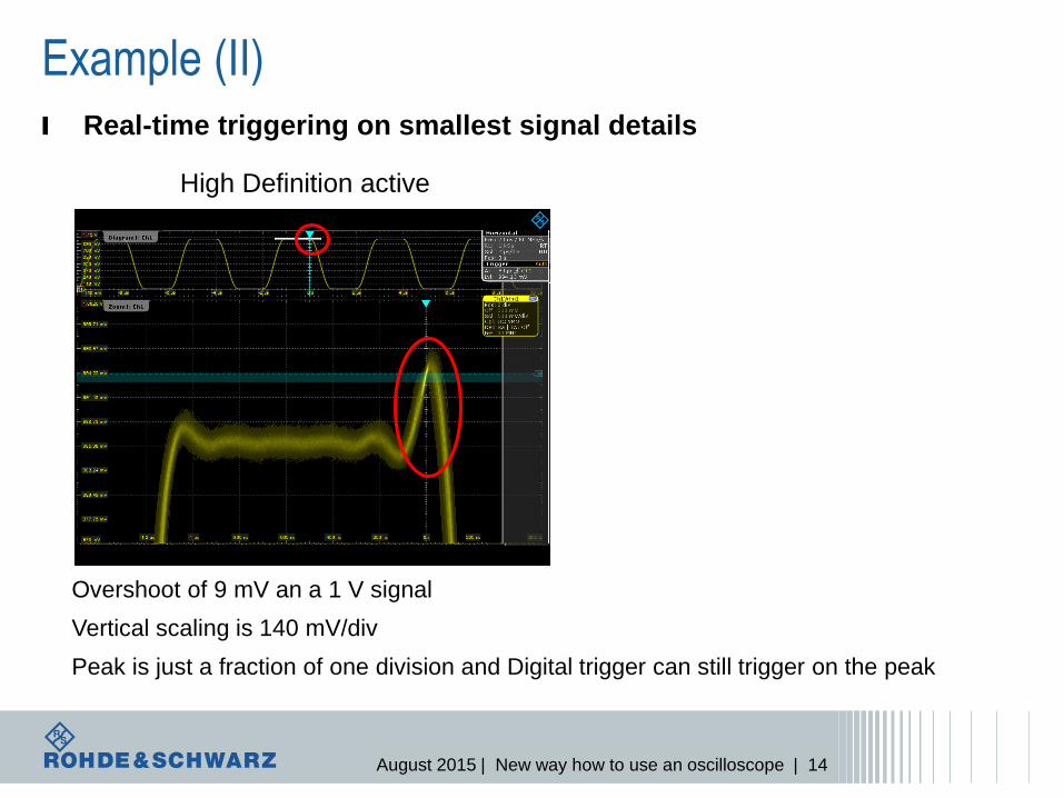
Example (II)
l Real-time triggering on smallest signal details
Overshoot of 9 mV an a 1 V signal
Vertical scaling is 140 mV/div
Peak is just a fraction of one division and Digital trigger can still trigger on the peak
High Definition active
August 2015 | New way how to use an oscilloscope | 15
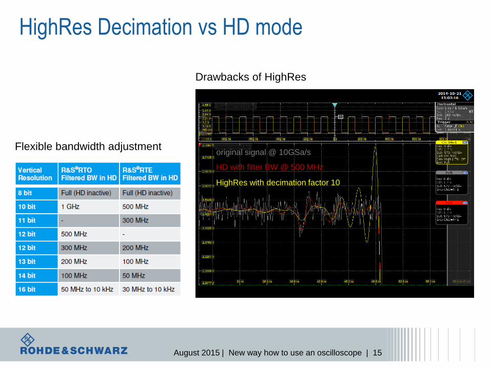
HighRes Decimation vs HD mode
Drawbacks of HighRes
HD with filter BW @ 500 MHz
original signal @ 10GSa/s
HighRes with decimation factor 10
Flexible bandwidth adjustment
August 2015 | New way how to use an oscilloscope | 16
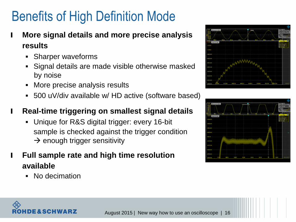
Benefits of High Definition Mode
l More signal details and more precise analysis
results
Sharper waveforms
Signal details are made visible otherwise masked
by noise
More precise analysis results
500 uV/div available w/ HD active (software based)
l Real-time triggering on smallest signal details
Unique for R&S digital trigger: every 16-bit
sample is checked against the trigger condition
enough trigger sensitivity
l Full sample rate and high time resolution
available
No decimation
August 2015 | New way how to use an oscilloscope | 17
Instrument
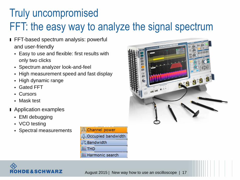
Truly uncompromised
FFT: the easy way to analyze the signal spectrum
ı FFT-based spectrum analysis: powerful
and user-friendly
Easy to use and flexible: first results with
only two clicks
Spectrum analyzer look-and-feel
High measurement speed and fast display
High dynamic range
Gated FFT
Cursors
Mask test
ı Application examples
EMI debugging
VCO testing
Spectral measurements
August 2015 | New way how to use an oscilloscope | 18
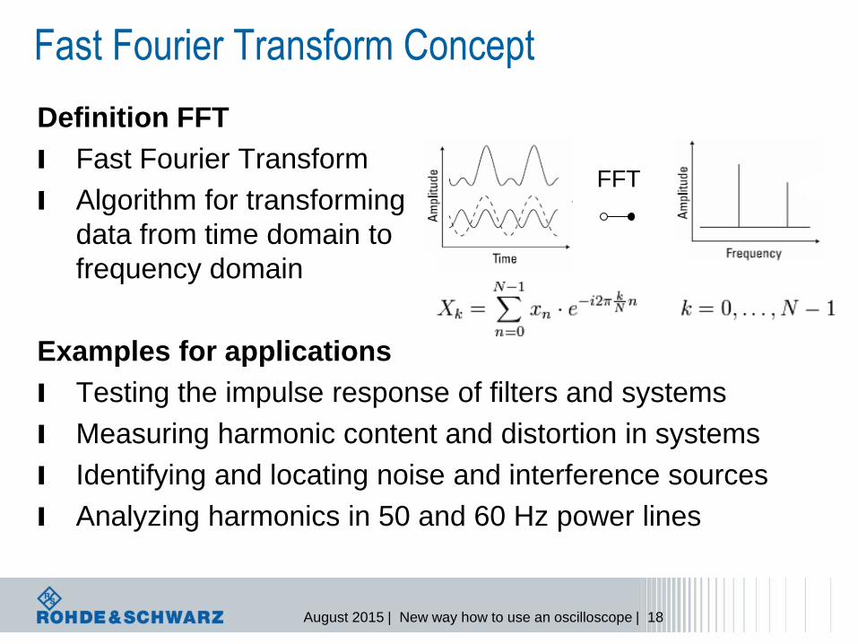
Fast Fourier Transform Concept
Definition FFT
l Fast Fourier Transform
l Algorithm for transforming
data from time domain to
frequency domain
Examples for applications
l Testing the impulse response of filters and systems
l Measuring harmonic content and distortion in systems
l Identifying and locating noise and interference sources
l Analyzing harmonics in 50 and 60 Hz power lines
FFT
August 2015 | New way how to use an oscilloscope | 19
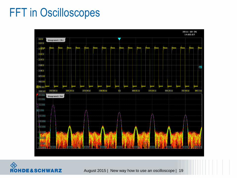
FFT in Oscilloscopes
August 2015 | New way how to use an oscilloscope | 20
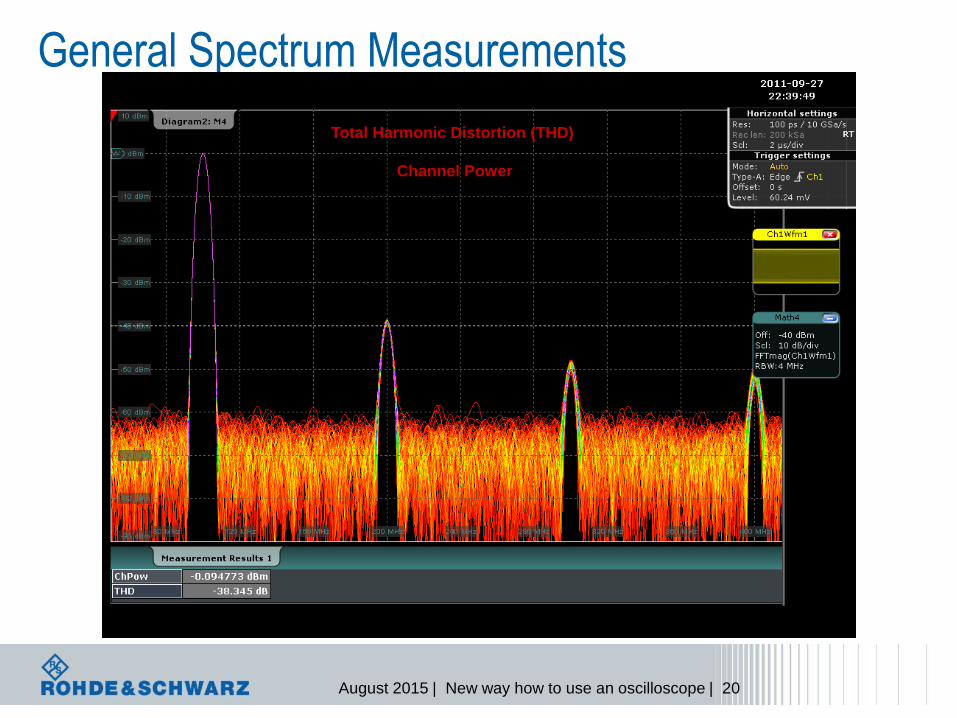
General Spectrum Measurements
Center = 2,4 GHz Span = 50 MHz
Total Harmonic Distortion (THD)
Channel Power
August 2015 | New way how to use an oscilloscope | 21
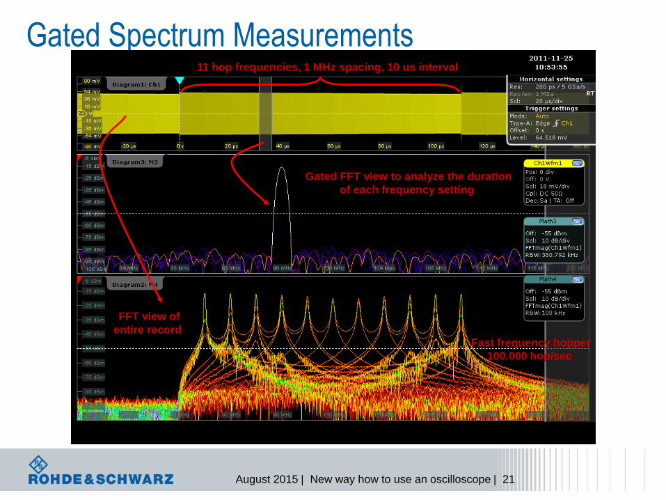
Gated Spectrum Measurements
Center = 2,4 GHz Span = 50 MHz
Fast frequency hopper
100.000 hop/sec
Gated FFT view to analyze the duration
of each frequency setting
11 hop frequencies, 1 MHz spacing, 10 us interval
FFT view of
entire record
August 2015 | New way how to use an oscilloscope | 22
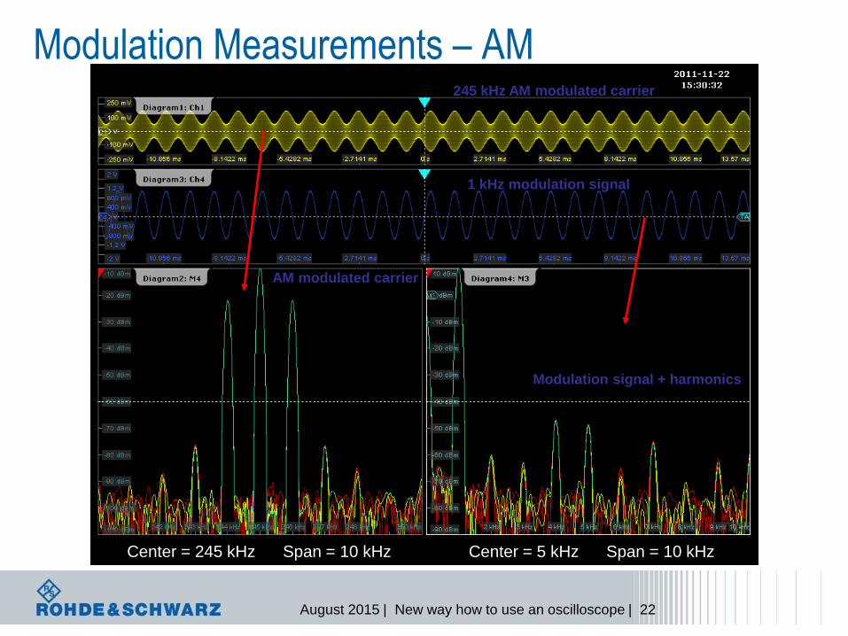
Modulation Measurements – AM
Center = 245 kHz Span = 10 kHz Center = 5 kHz Span = 10 kHz
245 kHz AM modulated carrier
1 kHz modulation signal
AM modulated carrier
Modulation signal + harmonics
August 2015 | New way how to use an oscilloscope | 23
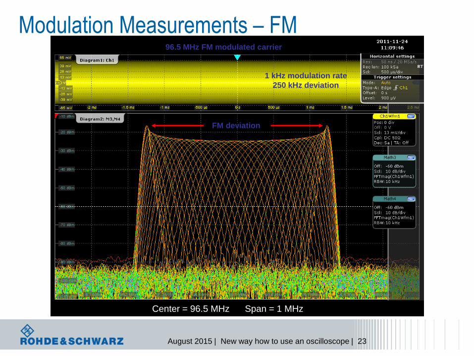
Modulation Measurements – FM
Center = 96.5 MHz Span = 1 MHz
96.5 MHz FM modulated carrier
1 kHz modulation rate
250 kHz deviation
FM deviation
August 2015 | New way how to use an oscilloscope | 24
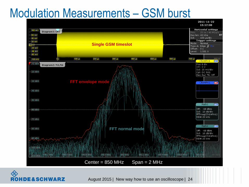
Modulation Measurements – GSM burst
Center = 850 MHz Span = 2 MHz
Single GSM timeslot
FFT envelope mode
FFT normal mode
August 2015 | New way how to use an oscilloscope | 25
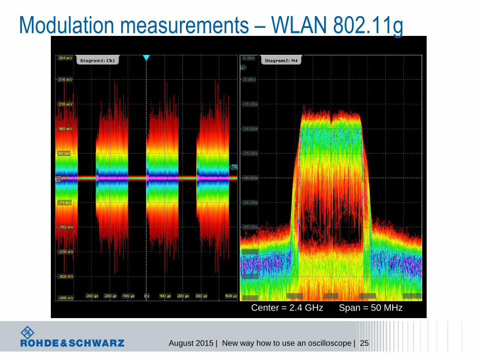
Modulation measurements – WLAN 802.11g
Center = 2.4 GHz Span = 50 MHz
August 2015 | New way how to use an oscilloscope | 26
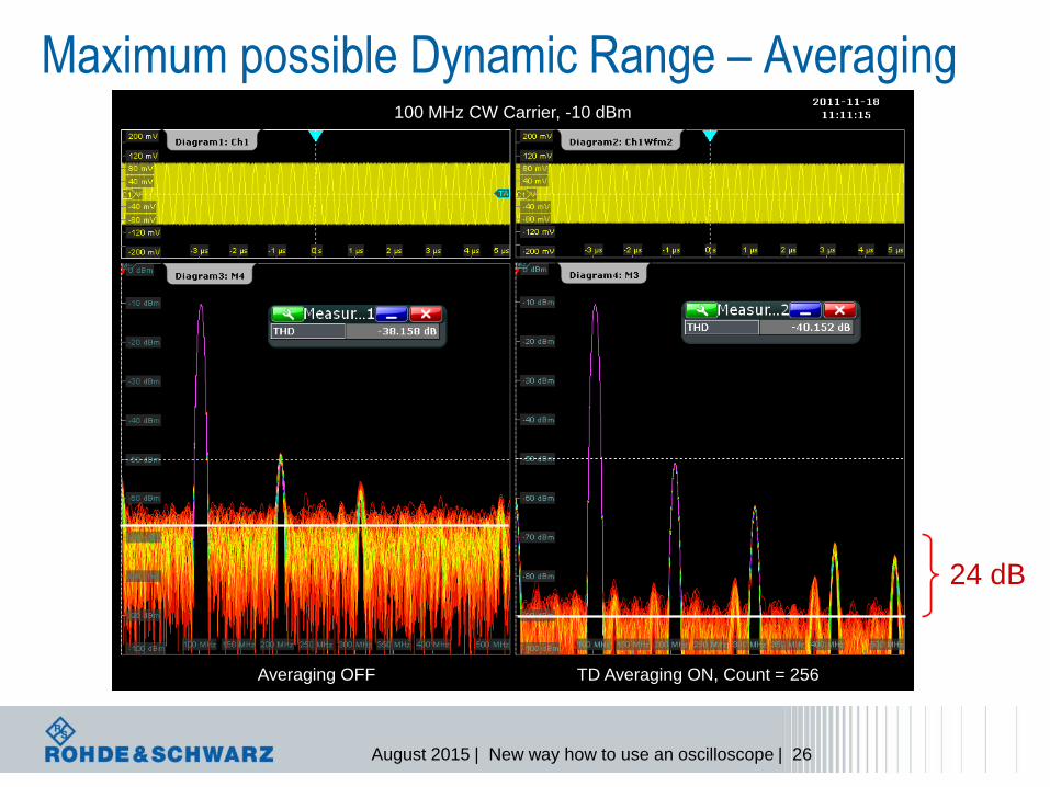
Maximum possible Dynamic Range – Averaging
Averaging OFF TD Averaging ON, Count = 256
100 MHz CW Carrier, -10 dBm
24 dB
August 2015 | New way how to use an oscilloscope | 27
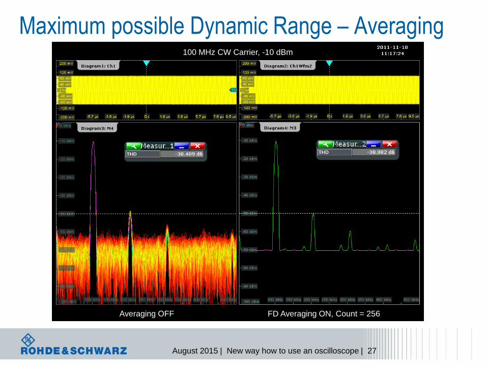
Maximum possible Dynamic Range – Averaging
Averaging OFF FD Averaging ON, Count = 256
100 MHz CW Carrier, -10 dBm
August 2015 | New way how to use an oscilloscope | 28
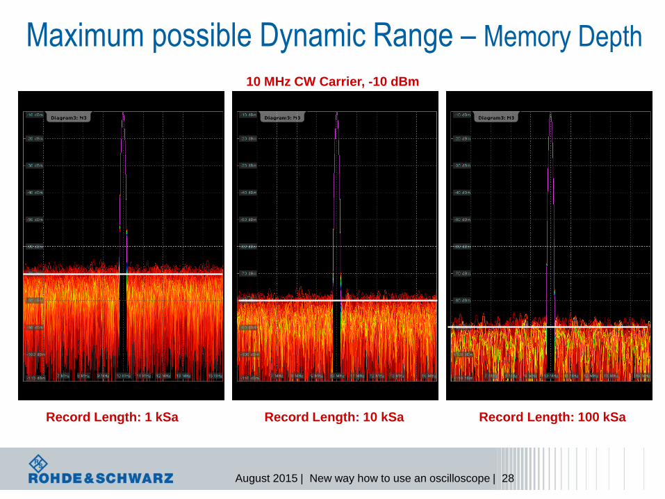
Maximum possible Dynamic Range – Memory Depth
Record Length: 1 kSa Record Length: 10 kSa Record Length: 100 kSa
10 MHz CW Carrier, -10 dBm

August 2015 | New way how to use an oscilloscope | 29
Instrument
FFT detection of low signals
l Signal -90 dBm (20mVP-P)
l Frequency 300MHz
August 2015 | New way how to use an oscilloscope | 30
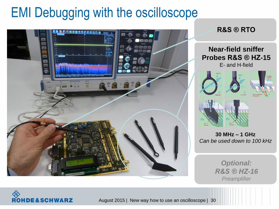
EMI Debugging with the oscilloscope
Near-field sniffer
Probes R&S ® HZ-15 E- and H-field
R&S ® RTO
30 MHz – 1 GHz
Can be used down to 100 kHz
Optional:
R&S ® HZ-16 Preamplifier
August 2015 | New way how to use an oscilloscope | 31
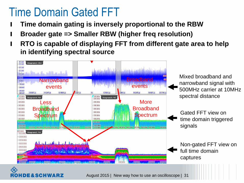
l Time domain gating is inversely proportional to the RBW
l Broader gate => Smaller RBW (higher freq resolution)
l RTO is capable of displaying FFT from different gate area to help
in identifying spectral source
Mixed broadband and
narrowband signal with
500MHz carrier at 10MHz
spectral distance
Narrowband
events
Broadband
events
Less
Broadband
Spectrum
More
Broadband
Spectrum Gated FFT view on
time domain triggered
signals
Non-gated FFT view on
full time domain
captures
Time Domain Gated FFT
August 2015 | New way how to use an oscilloscope | 32
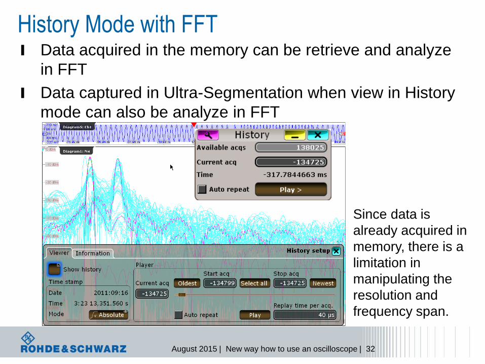
l Data acquired in the memory can be retrieve and analyze
in FFT
l Data captured in Ultra-Segmentation when view in History
mode can also be analyze in FFT
Since data is
already acquired in
memory, there is a
limitation in
manipulating the
resolution and
frequency span.
History Mode with FFT
August 2015 | New way how to use an oscilloscope | 33
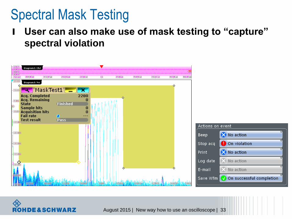
l User can also make use of mask testing to “capture”
spectral violation
Spectral Mask Testing
August 2015 | New way how to use an oscilloscope | 34
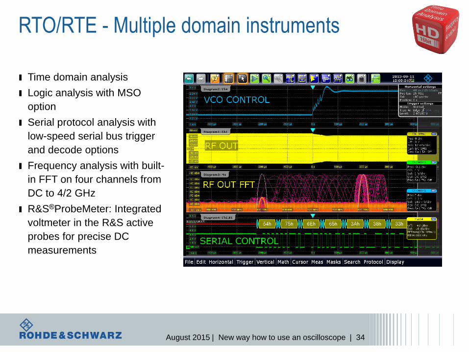
RTO/RTE - Multiple domain instruments
ı Time domain analysis
ı Logic analysis with MSO
option
ı Serial protocol analysis with
low-speed serial bus trigger
and decode options
ı Frequency analysis with built-
in FFT on four channels from
DC to 4/2 GHz
ı R&S®ProbeMeter: Integrated
voltmeter in the R&S active
probes for precise DC
measurements
August 2015 | New way how to use an oscilloscope | 35
Time for questions…