Embed Size (px)
Citation preview

Institute of Electrical Energy Conversion
Prof. A. Binder : New technologies of electric energy convertersand actuators
3_2/1
DARMSTADT UNIVERSITY OF TECHNOLOGY
3. Magnetic bearings („magnetic levitation“)
3.1 Basics of magnetic levitation
3.2 Electro-magnetic levitation
3.3 Electro-dynamic levitation
3.4 High speed trains with magnetic levitation
3.5 Superconducting magnetic bearings
New technologies of electric New technologies of electric energy converters and actuatorsenergy converters and actuators

Institute of Electrical Energy Conversion
Prof. A. Binder : New technologies of electric energy convertersand actuators
3_2/2
DARMSTADT UNIVERSITY OF TECHNOLOGY
3.3 Electro-dynamic levitation
Institute of Electrical Energy Conversion
Prof. A. Binder : New technologies of electric energy convertersand actuators
3_2/3
DARMSTADT UNIVERSITY OF TECHNOLOGY
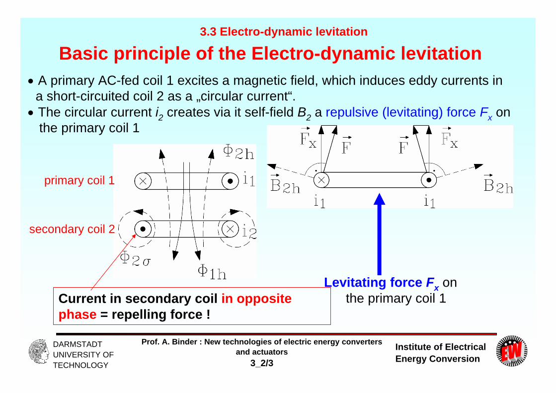
Basic principle of the Electro-dynamic levitation A primary AC-fed coil 1 excites a magnetic field, which induces eddy currents in a short-circuited coil 2 as a „circular current“.
The circular current i2 creates via it self-field B2 a repulsive (levitating) force Fx on the primary coil 1
3.3 Electro-dynamic levitation
Levitating force Fx on the primary coil 1 Current in secondary coil in opposite
phase = repelling force !
primary coil 1
secondary coil 2
Institute of Electrical Energy Conversion
Prof. A. Binder : New technologies of electric energy convertersand actuators
3_2/4
DARMSTADT UNIVERSITY OF TECHNOLOGY
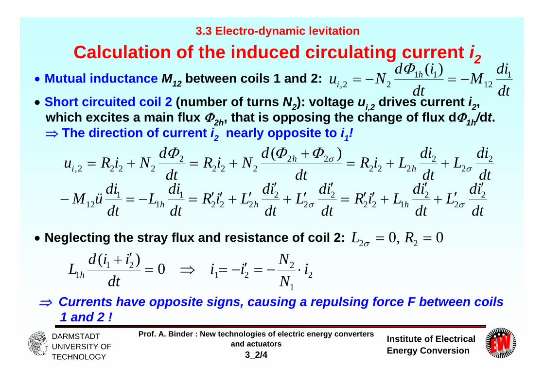
Calculation of the induced circulating current i2 Mutual inductance M12 between coils 1 and 2:
Short circuited coil 2 (number of turns N2): voltage ui,2 drives current i2,which excites a main flux 2h, that is opposing the change of flux d1h/dt. The direction of current i2 nearly opposite to i1!
dtdiM
dtidNu h
i1
1211
22,)(
dtdiL
dtdiLiR
dtdNiR
dtdNiRu h
hi
22
2222
22222
22222,
)(
dtidL
dtidLiR
dtidL
dtidLiR
dtdiL
dtdiüM hhh
22
2122
22
2222
11
112
Neglecting the stray flux and resistance of coil 2: 0,0 22 RL
21
221
211 0)( i
NNii
dtiidL h
Currents have opposite signs, causing a repulsing force F between coils 1 and 2 !
3.3 Electro-dynamic levitation

Institute of Electrical Energy Conversion
Prof. A. Binder : New technologies of electric energy convertersand actuators
3_2/5
DARMSTADT UNIVERSITY OF TECHNOLOGY
EML and EDL comparedElectro-magnetic levitation Electro-dynamic levitation
3.3 Electro-dynamic levitation
Attractive force due to ferromagnetism Repulsing force due to eddy currents

Institute of Electrical Energy Conversion
Prof. A. Binder : New technologies of electric energy convertersand actuators
3_2/6
DARMSTADT UNIVERSITY OF TECHNOLOGY
Mirror principle for calculating forces• Mirrored current flow in lower half space for calculation of EML and EDL forces
3.3 Electro-dynamic levitation
Mirrored current flow

Institute of Electrical Energy Conversion
Prof. A. Binder : New technologies of electric energy convertersand actuators
3_2/7
DARMSTADT UNIVERSITY OF TECHNOLOGY
Example for mirror calculation: Miyazaki track Infinitely long pair of parallel line conductors, distance 2a, distance d of
primary coil above the conducting surface yields a repulsing vertical force:
d
dIlF
4/
2
022 da
Example:Long moving superconducting DC excited coils as primary coils for the Japanesehigh speed train with EDL (7 km Miyazaki-test track, Kyushu)Coil length l = 1.7 m, width 2a = 0.5 m, number of turns/coil N = 1167, coil current i = 600 A, levitation distance d = 10 cm: = 0.269 m, I = N.i = 700.2 kA
269.01.0
1.0269.0
269.047002001047.1
27
F = 718.3 kN per coil side
Idealized levitation force per coil: 1436.5 kN (equals 146.4 tons)
3.3 Electro-dynamic levitation

Institute of Electrical Energy Conversion
Prof. A. Binder : New technologies of electric energy convertersand actuators
3_2/8
DARMSTADT UNIVERSITY OF TECHNOLOGY
Electro-dynamic levitation – Miyazaki-test track/Japan
MAGLEV train high speed test vehicle with aerodynamic emergency brakes,test track distance 7 km
Guiding and driving winding coils on both sides of the track
Short circuited coils in the track in driving direction for MAGLEV
Vehicle mass 20 t
Max. speed 420 km/h
3.3 Electro-dynamic levitation
Source: RTRI/Japan

Institute of Electrical Energy Conversion
Prof. A. Binder : New technologies of electric energy convertersand actuators
3_2/9
DARMSTADT UNIVERSITY OF TECHNOLOGY
D.C. operated levitated coil Moving coil, excited with DC current Is (e.g. superconducting current). Moves with velocity vs in x-direction over a conducting plate or a row of short-circuited fixed coils
Coil field Bs induces in the fixed short-circuited coils an eddy current Ip, which creates with Bs a levitation (repulsing) force Fz, that gives a stable levitation to the moving coil. A (disturbing) braking force Fx on the coil occurs a the same time.
3.3 Electro-dynamic levitation
Secondary: conducting plate
Secondary: row of short-circuited fixed coils
Komarek, P.: Teubner, Stuttgart, 1995
x
zy
z

Institute of Electrical Energy Conversion
Prof. A. Binder : New technologies of electric energy convertersand actuators
3_2/10
DARMSTADT UNIVERSITY OF TECHNOLOGY
Levitation force Fz and braking force Fx
Coils excited with DC current Is are moving with vs over a sequence of short-circuited fixed coils and induce an eddy current Ip per coil, which gives a levitation (repulsing) force Fzand braking force Fx.
Levitation force Fz Braking force Fx
3.3 Electro-dynamic levitation
Komarek, P.: Teubner, Stuttgart, 1995
vs/v0vs/v0 0 000 12
0.8Fmax
Fmax
Rm = vs/v0: magnetische Reynolds-Zahl

Institute of Electrical Energy Conversion
Prof. A. Binder : New technologies of electric energy convertersand actuators
3_2/11
DARMSTADT UNIVERSITY OF TECHNOLOGY
Braking force Fx and loss of energy P(vs) Frequency of induced voltage (in coils):
Moving DC coils replaced by non-moving AC coils: Current is with frequency fp:
)2/( psp vf
ppppshpppsshp ILjILjIRILj
Current in short circuited coil:)(
pshpp
sshpp LLjR
ILjI
I2R losses P in the secondary coil as current heat (L´p 0): Power balance Braking force Fx
sxsp
pshps
pshps
shpp
sshpppp vFIR
RLvRLv
LRILR
IRP
22
2
22
22
//1//
)()(
with gives:)/()/(0 pshp LRv 22
0
20
)/(1/
sps
sx IR
vvvv
F
3.3 Electro-dynamic levitation

Institute of Electrical Energy Conversion
Prof. A. Binder : New technologies of electric energy convertersand actuators
3_2/12
DARMSTADT UNIVERSITY OF TECHNOLOGY
Influence of coil dimensions on braking force Coil inductance: z: vertical distance of coilszlNL pssh /~ 2
0
)/()(2
)/( 2
pcoil
pppsp NA
lNNNR
Coil resistance:
Magnetic Reynolds-number Rm = vs/v0 : withlz
ALR
vcoil
pp
sh
p
00
2~
Magnetic Reynolds-number is free of units & describes relative coil velocity.
Braking force:
The braking force Fx is zero near very low and very high Rmand has its maximum at Rm = 1.
22
20
2
1~
1 m
ms
m
mspx
RRB
RR
vIR
F
3.3 Electro-dynamic levitation

Institute of Electrical Energy Conversion
Prof. A. Binder : New technologies of electric energy convertersand actuators
3_2/13
DARMSTADT UNIVERSITY OF TECHNOLOGY
Calculation of levitation force Fz Field of DC coil: , mathematical model as AC field for alternating current:
Short circuited current Ip´: Component I´p,real in phase with Bs: It creates arepulsing force Fz:
zIB ss /~ 0zIB ss /~ 0
)(2 , lBINF psrealpsz
With Lp 0 we get: 20
20
222
22
, )/(1)/(
)(Re
vvIvv
LR
ILLLjR
ILjI
s
ss
shpp
sshp
pshpp
sshprealp
Repulsing (levitating) force:
2
22
20
20
2
,0,1)/(1
)/(~)/(~~m
ms
s
sssrealpsrealpz
RR
zI
vvvv
zIzIIBIF
- High Rm : Maximum levitation force at Rm = 2 already 80% of max. force- v0 must be low: Low resistance Rp of secondary coils: Np = 1, high
conductivity , big coil conductor cross section ACu = Acoil.- High mutual inductance Lsh Low levitation distance z necessary
3.3 Electro-dynamic levitation

Institute of Electrical Energy Conversion
Prof. A. Binder : New technologies of electric energy convertersand actuators
3_2/14
DARMSTADT UNIVERSITY OF TECHNOLOGY
Condition for electro-dynamic levitation Levitation force depends on square of Is resp. flux density Bs:
high coil-flux density Bs e.g.: 5 – 6 T necessary for big z
Big Bs demands big excitation current Is: Therefore low-loss excitation essential: Solution: Superconducting DC coil excitation
“Magnetic spring curve” Fz(z) ~ 1/z. At low levitation distance strong rising of repulsing force: typical levitation distance z = 10 cm
Minimum speed of moving DC coils necessary for levitation
Magnetic rail way with electro-dynamic levitation needs wheels for acceleration and braking. „Take-off“ at minimum speed (Yamanashi: Take-off at about 100 km/h)
3.3 Electro-dynamic levitation

Institute of Electrical Energy Conversion
Prof. A. Binder : New technologies of electric energy convertersand actuators
3_2/15
DARMSTADT UNIVERSITY OF TECHNOLOGY
Self-stable electro-dynamic levitation3.3 Electro-dynamic levitation
Fz
z0
Fz= F0.z0/z
Fg= m.g
z0
z
gmzzFFFzm gz 0
0
gmzz
zFzm
0
00
1/ 00 zzzzzgmFzzFF gz 00 :0
Newton´s law of motion for vertical axis:Equilibrium point:
Small disturbance of equilibrium:
gmzzFzm )/1( 00
0)/( 00 zzFzm
Solution of homogeneous 2nd order linear differential equation: tZtz cosˆ)(
)/( 00 zmF
Un-damped, but stable oscillation of the levitated body after disturbance Zz ˆ)0(

Institute of Electrical Energy Conversion
Prof. A. Binder : New technologies of electric energy convertersand actuators
3_2/16
DARMSTADT UNIVERSITY OF TECHNOLOGY
Numerical field calculation for electro-dynamic levitation
Velocity of coil vx
Coil with DC current
Conductive Alu-plate
Lateral dislocation of the coil y
Model geometry Model dimensions
Source: AEG, Germany
Ele. conductivity 35 MS/m
z0: levitation distance
3.3 Electro-dynamic levitation
b =

Institute of Electrical Energy Conversion
Prof. A. Binder : New technologies of electric energy convertersand actuators
3_2/17
DARMSTADT UNIVERSITY OF TECHNOLOGY
Sketch of the distribution of the normal component of the magnetic field of the DC coil at the plate surface
vx
Coil with DC current
Conductive Alu-plate
Vx = 0Bz ~
/cm
Ampere-turns: = NI
Result:The DC excited coil field has at vx = 0 a symmetrical distribution!
So no longitudinal braking force exists!
3.3 Electro-dynamic levitation
Source: AEG, Germany

Institute of Electrical Energy Conversion
Prof. A. Binder : New technologies of electric energy convertersand actuators
3_2/18
DARMSTADT UNIVERSITY OF TECHNOLOGY
Repulsive normal force Fz in dependence of the coil velocity vx
Fz/N
Levitation distance z0 = 90 mm:a) Infinitely broad Alu plate
b) Alu plate breadth b = 160 mm
Maximum force at vx : a) 160 N, b) ca. 130 N
Levitation distance z0 = 70 mm:b) Alu plate breadth b = 160 mm
Maximum force at vx : ca. 330 N
3.3 Electro-dynamic levitation
Source: AEG, Germany

Institute of Electrical Energy Conversion
Prof. A. Binder : New technologies of electric energy convertersand actuators
3_2/19
DARMSTADT UNIVERSITY OF TECHNOLOGY
Braking longitudinal force Fx in dependence of the coil velocity vx
Fx/NLevitation distance z0 = 90 mm:b) Alu plate breath b = 160 mm
a) Infinitely broad Alu plate
Levitation distance z0 = 70 mm:b) Alu plate breadth b = 160 mm
Result: Maximum braking force at small velocities: ca. 8 … 12 m/s
3.3 Electro-dynamic levitation
Source: AEG, Germany

Institute of Electrical Energy Conversion
Prof. A. Binder : New technologies of electric energy convertersand actuators
3_2/20
DARMSTADT UNIVERSITY OF TECHNOLOGY
Calculate eddy current density in the Aluminum plate at rising coil velocities
Vx = 18 km/h
Vx = 36 km/h
Vx = 540 km/h
Direction of eddy currents opposite to the DC coil current direction!
Eddy current “tail” yields a resulting asymmetric total field, which causes the (maximum) braking force
3.3 Electro-dynamic levitation
Source: AEG, Germany
Institute of Electrical Energy Conversion
Prof. A. Binder : New technologies of electric energy convertersand actuators
3_2/21
DARMSTADT UNIVERSITY OF TECHNOLOGY
Summary: Electro-dynamic levitation
- Repulsive force due to induced eddy currents used as levitation force- No ferro-magnetics allowed due to their counteracting attracting force- AC or moving DC coils used as exciter- Self-stable levitation- Superconducting moving DC coils as exciter- With SC rather large levitation gaps possible
New technologies of electric energy converters and New technologies of electric energy converters and actuatorsactuators

Institute of Electrical Energy Conversion
Prof. A. Binder : New technologies of electric energy convertersand actuators
3_2/22
DARMSTADT UNIVERSITY OF TECHNOLOGY
3. Magnetic bearings („magnetic levitation“)
3.1 Basics of magnetic levitation
3.2 Electro-magnetic levitation
3.3 Electro-dynamic levitation
3.4 High speed trains with magnetic levitation
3.5 Superconducting magnetic bearings
New technologies of electric New technologies of electric energy converters and actuatorsenergy converters and actuators

Institute of Electrical Energy Conversion
Prof. A. Binder : New technologies of electric energy convertersand actuators
3_2/23
DARMSTADT UNIVERSITY OF TECHNOLOGY
3.4 High speed trains with magnetic levitation (MAGLEV)
Source: Siemens AG, Germany

Institute of Electrical Energy Conversion
Prof. A. Binder : New technologies of electric energy convertersand actuators
3_2/24
DARMSTADT UNIVERSITY OF TECHNOLOGY
Magnetic levitation railways (MAGLEV) - overview3.4 High speed trains with magnetic levitation
TRANSRAPID/Germany HSST/Japan Yamanashi/Japan
Long stator motor Short stator motor Long stator motor
Electromagnetic levitation Electro-dynamic levitation
Source: Thyssen Krupp,
Germany
Long linear motor in the track
Attractive force
Short linear motor in the vehicle
Attractive force
Long linear motor in the track
Repulsive self-stable force

Institute of Electrical Energy Conversion
Prof. A. Binder : New technologies of electric energy convertersand actuators
3_2/25
DARMSTADT UNIVERSITY OF TECHNOLOGY
3.4 High speed trains with magnetic levitation
3.4.1 Active magnetically levitated high-speed train TRANSRAPID
3.4.2 Japanese electro-dynamically levitated high-speed train YAMANASHI
New technologies of electric New technologies of electric energy converters and actuatorsenergy converters and actuators
Institute of Electrical Energy Conversion
Prof. A. Binder : New technologies of electric energy convertersand actuators
3_2/26
DARMSTADT UNIVERSITY OF TECHNOLOGY
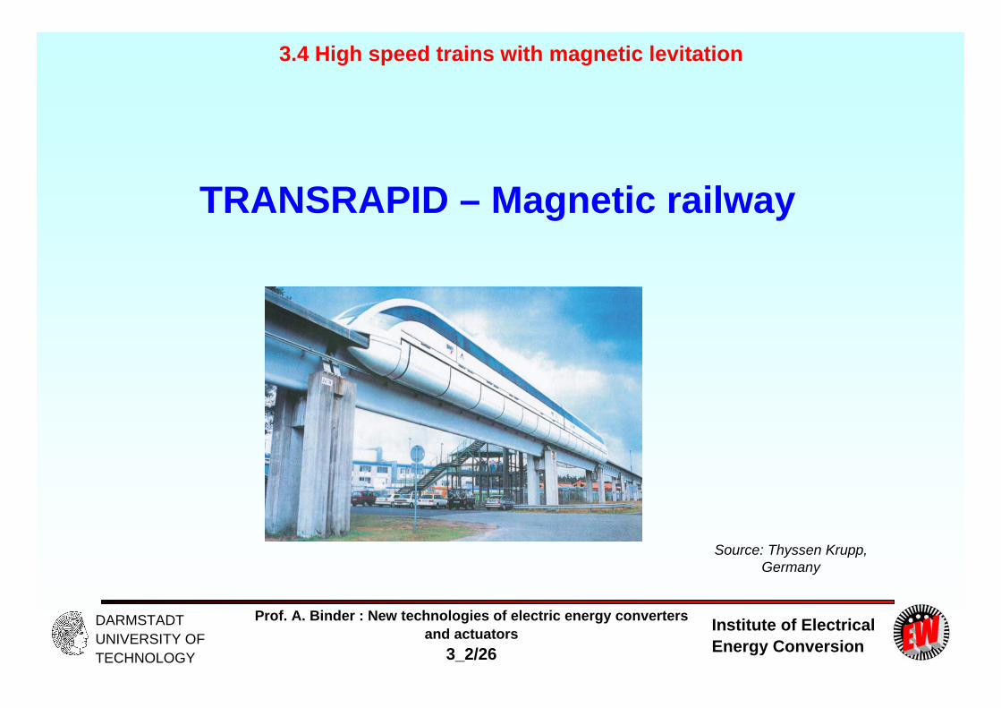
TRANSRAPID – Magnetic railway
3.4 High speed trains with magnetic levitation
Source: Thyssen Krupp, Germany

Institute of Electrical Energy Conversion
Prof. A. Binder : New technologies of electric energy convertersand actuators
3_2/27
DARMSTADT UNIVERSITY OF TECHNOLOGY
TRANSRAPID – System TR07 Electromagnetic levitation: DC magnets under T-formed vehicle
with levitation gap of about 10 mm. Vehicle distance to track 15 cm.
Levitation DC-excited magnets are electrical secondary excitation of asynchronous linear long-stator motor: Nf,Pol = 230 turns per coil/magnet.
Guiding side-magnetic forces to keep the vehicle on centre of the track
Long stator: Travelling wave long-stator 3-phase, AC winding q = 1, m = 3, Nc = 1 (cable winding) with stator iron core with open slots, winding section feeding by inverters, position detection of train via radio
Linear synchronous generator in „medium frequency"-layout: Generator 2-phase AC winding (q = 1, m = 2, single layer) in slots in the secondary magnet pole-shoes: the open stator slots "modulate" the secondary DC field, yielding a slot-frequent AC component, which induces the generator winding with a voltage with „slot frequency“. Above 85 km/h this rectified voltage is big enough for loading of the 440 V-board battery.
3.4 High speed trains with magnetic levitation

Institute of Electrical Energy Conversion
Prof. A. Binder : New technologies of electric energy convertersand actuators
3_2/28
DARMSTADT UNIVERSITY OF TECHNOLOGY
Magnetic levitation of high speed train TRANSRAPID
- Active controlled magnetic levitation and guidance system
- Electrical linear synchronous motor for thrust
3.4 High speed trains with magnetic levitation
Source: Thyssen Krupp, Germany
150 mm
10 mmLevitation magnet
Side magnet
Massive iron side rail
Source: Siemens AG, Germany

Institute of Electrical Energy Conversion
Prof. A. Binder : New technologies of electric energy convertersand actuators
3_2/29
DARMSTADT UNIVERSITY OF TECHNOLOGY
TRANSRAPID – Levitation, guidance and propulsion system
3.4 High speed trains with magnetic levitation
Source: Thyssen Krupp, Germany
Side magnet
Massive iron side rail
Levitation magnet
Institute of Electrical Energy Conversion
Prof. A. Binder : New technologies of electric energy convertersand actuators
3_2/30
DARMSTADT UNIVERSITY OF TECHNOLOGY
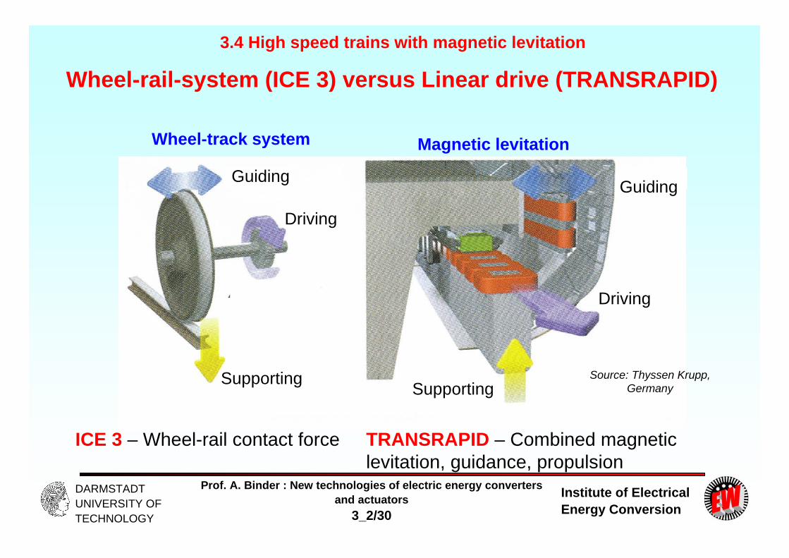
Wheel-rail-system (ICE 3) versus Linear drive (TRANSRAPID)
ICE 3 – Wheel-rail contact force TRANSRAPID – Combined magnetic levitation, guidance, propulsion
3.4 High speed trains with magnetic levitation
Source: Thyssen Krupp, Germany
Wheel-track system Magnetic levitation
Driving
Driving
Guiding Guiding
Supporting Supporting

Institute of Electrical Energy Conversion
Prof. A. Binder : New technologies of electric energy convertersand actuators
3_2/31
DARMSTADT UNIVERSITY OF TECHNOLOGY
Magnetic travelling field „pulls“ the vehicle „synchronously“
Instead of a rotary field in rotary motor, we have a travelling field of a „linear“long-stator winding
DC magnets of the magnetic bearing are the poles, that are pulled by the travelling stator field “synchronously“ = SYNCHRONOUS LINEAR MOTOR.
Velocity of stator travelling field wave = Speed of vehiclev = 2 f p = 2.215.0.258 = 111 m/s = 400 km/h (Shanghai / Pudong)
3.4 High speed trains with magnetic levitation
Source: Thyssen Krupp, Germany
travelling field wave

Institute of Electrical Energy Conversion
Prof. A. Binder : New technologies of electric energy convertersand actuators
3_2/32
DARMSTADT UNIVERSITY OF TECHNOLOGY
Levitation and guidance of TRANSRAPID
Levitation magnets pull from below at a gap distance 10 ...13 mm the vehicle to the stator iron of the linear motor, which lies fixed in the track. So the vehicle gets ABOVE the track a clearance of 150 mm.
Thrust force Guidance force
Levitation force
Levitation magnet
Guiding magnet
3.4 High speed trains with magnetic levitation
Source: Thyssen Krupp, Germany

Institute of Electrical Energy Conversion
Prof. A. Binder : New technologies of electric energy convertersand actuators
3_2/33
DARMSTADT UNIVERSITY OF TECHNOLOGY
Three phase long stator winding in stator iron stack
- Three-phase windings U, V, W: Wave-wound winding, made from aluminum MV cable
- Pole pitch: 258 mm, units of 4 poles = 1032 mm, 24 units = 1 section = 24.768 m, iron width 185 mm, two motors left and right of the track
- Several coupled sections create a “supply section”: In Shanghai: 0.9 ... 5.0 km
- About 180 poles fit under one total vehicle length ( = 46 m length)
UW
V
Stator iron stack
3.4 High speed trains with magnetic levitation
Source: ThyssenKrupp, Germany
Massive iron side railT-shaped track
Stator laminated iron stack
Stator stack fixation

Institute of Electrical Energy Conversion
Prof. A. Binder : New technologies of electric energy convertersand actuators
3_2/34
DARMSTADT UNIVERSITY OF TECHNOLOGY
TRANSRAPID-07-long stator winding
TRANSRAPID test track in Emsland, Germany
Synchronous long stator winding:
Laminated stator iron stack, open slots and three-phase AC travelling field wave winding, made of MV aluminum cables as wave winding = 1 coil per pole and phase
3.4 High speed trains with magnetic levitation
Source: Thyssen Krupp, Germany

Institute of Electrical Energy Conversion
Prof. A. Binder : New technologies of electric energy convertersand actuators
3_2/35
DARMSTADT UNIVERSITY OF TECHNOLOGY
Linear 3-ph. syn. motor and linear 2-ph. syn. generator3.4 High speed trains with magnetic levitation
Source: PhD Thesis Dr. Fürst, TU Berlin
Prototype 3-ph. long stator winding in Emsland of MV copper cable
Linear generator: Phase aPhase b
Coil width = half stator slot pitch Qs/6 = p/6
Laminated iron stack
Slot housing
Slot wedge
Stator winding
Motor cableCu screen
Cu conductor
Stator slot
Pole face of secondary magnet
Stator stack
Pole pitch
Stator winding
Linear generatorExcitation windingIron of secondary magnet

Institute of Electrical Energy Conversion
Prof. A. Binder : New technologies of electric energy convertersand actuators
3_2/36
DARMSTADT UNIVERSITY OF TECHNOLOGY
Design of the TRANSRAPID linear drive Pole pitch p small to have small flux per pole: Small iron yoke height = small iron masses, short winding overhangs = small conductor masses = saving of material. BUT: Small pole-pitch: High max. fundamental frequency fs for high train speed: p = 258 mm:
Air-gap flux density ca. 0.64 T demands exciting Ampere-turns Nf,pole.If.
km/h5002 max,max, pssyn fv Hz269max, sf
Vehicle length 46 m: 46/0.258 = about 180 pole pitches (= 90 pole pairs) covered by the vehicle.Number of turns per stator winding phase: 901/1190/ aNqpN c
Nominal current Is = 1200 A, electric loading:
Cable diameter 18mm: current density:
Thermal loading:Short time operation with natural air cooling by convection
A/cm5.1398.25902
1200903222
p
ss p
mNIA
22 A/mm7.4
4/181200
Cu
ss q
IJ2A/mmA/cm660 ss JA
3.4 High speed trains with magnetic levitation

Institute of Electrical Energy Conversion
Prof. A. Binder : New technologies of electric energy convertersand actuators
3_2/37
DARMSTADT UNIVERSITY OF TECHNOLOGY
Propulsion and levitation system of TRANSRAPID Electromagnetic thrust/surface:
Thrust force F per vehicle at 2x150 secondary magnets: lFe = 185 mm
Us = 4675V: Constant thrust up to vmax = 370 km/h:
Levitation system: Vehicle mass: m = 100 t Weight force: m.g = 981 kN
Levitation force per magnet:
(Pole surface A = 20 400 mm2)
Levitation force per vehicle: sufficient!
1N/m63132
64.0139502
2
ws
w kBA
k
kN4.902185.0258.0150631322 FeplpF
MW3.9maxmax vFP
kN3.310204001042
64.02
67
2
0
2
ABFLev
kN9903.32150, totLevF
A71334.101.010464.0
70
,
CfPolff kBINVExciting Ampere-turns:
A312307133
,
Polf
ff N
VIField current If per magnet:
3.4 High speed trains with magnetic levitation
Institute of Electrical Energy Conversion
Prof. A. Binder : New technologies of electric energy convertersand actuators
3_2/38
DARMSTADT UNIVERSITY OF TECHNOLOGY
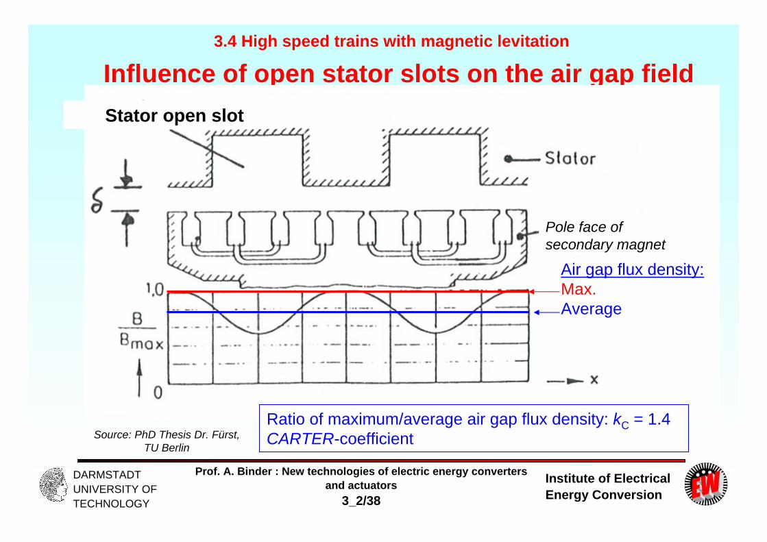
Influence of open stator slots on the air gap field3.4 High speed trains with magnetic levitation
Source: PhD Thesis Dr. Fürst, TU Berlin
Stator open slot
Air gap flux density:Max.Average
Ratio of maximum/average air gap flux density: kC = 1.4CARTER-coefficient
Pole face of secondary magnet

Institute of Electrical Energy Conversion
Prof. A. Binder : New technologies of electric energy convertersand actuators
3_2/39
DARMSTADT UNIVERSITY OF TECHNOLOGY
Secondary pole shifting to reduce force oscillations3.4 High speed trains with magnetic levitation
- Stator integer slot winding & secondary poles un-skewed, so slot openings cause field and hence force ripple, when the car is moving.
- A skewing by one slot pitch s is recommended to reduce this ripple.
- By having a secondary pole pitch f different to the stator pole pitch p, a pole shifting by one slot pitch per 12 poles occurs, which can also equalize the force ripple.
- A secondary pole module comprises 10 centre poles and 2 half end poles, with different pole pitch: centre poles: f = 266.5 mm, end poles: ´f = 262.5 mm
- Resulting shift: xshift = 9(f - p) + 2(´f - p) = 84.9 mm s = 86 mm Source: Thyssen Krupp, Germany
Institute of Electrical Energy Conversion
Prof. A. Binder : New technologies of electric energy convertersand actuators
3_2/40
DARMSTADT UNIVERSITY OF TECHNOLOGY
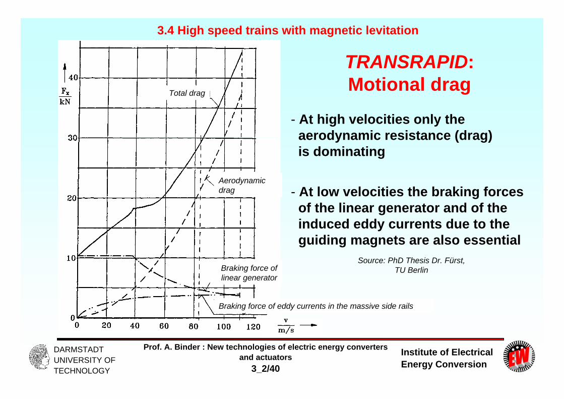
TRANSRAPID: Motional drag
- At high velocities only the aerodynamic resistance (drag) is dominating
- At low velocities the braking forces of the linear generator and of the induced eddy currents due to the guiding magnets are also essential
3.4 High speed trains with magnetic levitation
Source: PhD Thesis Dr. Fürst, TU Berlin
Total drag
Aerodynamic drag
Braking force of linear generator
Braking force of eddy currents in the massive side rails

Institute of Electrical Energy Conversion
Prof. A. Binder : New technologies of electric energy convertersand actuators
3_2/41
DARMSTADT UNIVERSITY OF TECHNOLOGY
Transrapid: On board current supply3.4 High speed trains with magnetic levitation
Source: PhD Thesis Dr. Fürst, TU Berlin
Linear generator
Diode rectifier bridge
Chopper for variable DC voltage
BatterySupply bus bar for emergency (now with contactless energy transfer via a 20 kHz-transformer arrangement)
Charging unit
Bus bar
Inverter
Levitation & Guiding magnets
Load e.g. Air condition Low voltage supply bar
Institute of Electrical Energy Conversion
Prof. A. Binder : New technologies of electric energy convertersand actuators
3_2/42
DARMSTADT UNIVERSITY OF TECHNOLOGY
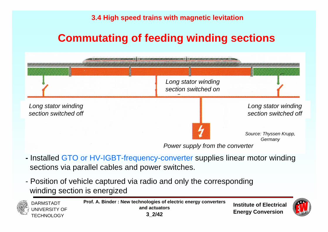
Commutating of feeding winding sections
- Installed GTO or HV-IGBT-frequency-converter supplies linear motor winding sections via parallel cables and power switches.
- Position of vehicle captured via radio and only the corresponding winding section is energized
3.4 High speed trains with magnetic levitation
Source: Thyssen Krupp, Germany
Long stator winding section switched on
Long stator winding section switched off
Long stator winding section switched off
Power supply from the converter

Institute of Electrical Energy Conversion
Prof. A. Binder : New technologies of electric energy convertersand actuators
3_2/43
DARMSTADT UNIVERSITY OF TECHNOLOGY
Radio security
Switch control
Track security
Radio security
Control area
Long distance system for train controlling and vehicle-securing
3.4 High speed trains with magnetic levitation
Source: Thyssen Krupp, Germany

Institute of Electrical Energy Conversion
Prof. A. Binder : New technologies of electric energy convertersand actuators
3_2/44
DARMSTADT UNIVERSITY OF TECHNOLOGY
Electrical supply of the linear stator winding3.4 High speed trains with magnetic levitation
Emsland test track: 50 Hz/110 kV-grid, 110 kV/20 kV-power transformers,along the track at different stations: Feeding points via PWM-voltage sourceconverters, built with GTO-modules
Converter transformers 20 kV/1120 V create two 30°el phase-shifted 3-ph. AC voltage systems, which are rectified = 12 pulse controlled rectification of the grid voltage via thyristors!
Voltage source inverter: DC link voltage 2.6 kV, PWM-output voltage up to55 Hz (= 102 km/h), 1170 V phase voltage (r.m.s.).
Between 55 … 270 Hz: Block-voltage operation, but phase shifted by the four output transformers to reduce the harmonic content of the output voltage and the stator current harmonic in the linear motor winding.Output voltage raised with these transformers up to 4x1170 = 4675 V up to 370 km/h constant thrust possible
Switching of feeding sections in “Alternate step mode”: Left and right linear motor winding changed from section to section time-shifted!

Institute of Electrical Energy Conversion
Prof. A. Binder : New technologies of electric energy convertersand actuators
3_2/45
DARMSTADT UNIVERSITY OF TECHNOLOGY
3.4 High speed trains with magnetic levitation
Source: Siemens AG, Germany
Energy supply of TRANSRAPID in
Emsland test track- 1995: GTO-converters
- Since 2006: Replaced by High-Voltage IGBT-technology
Sub-station
Supply grid
HV transformer 110 kV / 20 kV
3-winding transformers
Converter:-12-pulse Rectifier- DC link- DC braker- 3-phase inverter
Step-up transformer
AR: Drive control
Supply cable
Switch
Vehicle position detection Motor winding feeding section

Institute of Electrical Energy Conversion
Prof. A. Binder : New technologies of electric energy convertersand actuators
3_2/46
DARMSTADT UNIVERSITY OF TECHNOLOGY
3.4 High speed trains with magnetic levitation
Source: Siemens AG, Germany
Energy supply of TRANSRAPID in Emsland test track
High voltage switchgear with transformer
110 kV/20 kV
Input switchgear
Line side thyristorconverter for dual
power flow

Institute of Electrical Energy Conversion
Prof. A. Binder : New technologies of electric energy convertersand actuators
3_2/47
DARMSTADT UNIVERSITY OF TECHNOLOGY
3.4 High speed trains with magnetic levitation
Source: Siemens AG, Germany
Energy supply of TRANSRAPID in Emsland test trackconverter water cooling system
GTO motor converter
Epoxy-resin step-up transformer
Propulsion regulation and control system
20 kV vacuum contactor output switch gear

Institute of Electrical Energy Conversion
Prof. A. Binder : New technologies of electric energy convertersand actuators
3_2/48
DARMSTADT UNIVERSITY OF TECHNOLOGY
Slope climbing ability of TRANSRAPID up to 10%
TRANSRAPID: Drive system stationary inside the track
ICE: Drive system totally on board of the vehicle
10%
Max. 4%
TRANSRAPID has higher climbing capability than ICE3, because:
- No wheel rail system, so no friction contact force as limit
- Thrust power of converter inside the track, so locally higher power supply possible
3.4 High speed trains with magnetic levitation
Source: Thyssen Krupp, Germany

Institute of Electrical Energy Conversion
Prof. A. Binder : New technologies of electric energy convertersand actuators
3_2/49
DARMSTADT UNIVERSITY OF TECHNOLOGY
Maximum acceleration for ICE 3 and TRANSRAPID
ICE 3 TRANSRAPID
0 ... 250 km/h 0.59 ...0.18 m/s2 0.74 m/s2
300 ... 350 km/h 0.03 m/s2 0.57 m/s2
350 ... 400 km/h vmax already surpassed 0.44 m/s2
3.4 High speed trains with magnetic levitation
Source: Thyssen Krupp, Germany

Institute of Electrical Energy Conversion
Prof. A. Binder : New technologies of electric energy convertersand actuators
3_2/50
DARMSTADT UNIVERSITY OF TECHNOLOGY
Travelling time - ICE 3 compared to TRANSRAPID
ICE 3 TRANSRAPID
vmax 300 km/h 400 km/h
Distance 20 km 7 min 6 min
vmax 330 km/h 400 km/h (possible:
450 ... 500 km/h) Distance 200 km 44 min 35 min
(ca. 29 min)
3.4 High speed trains with magnetic levitation
Source: Thyssen Krupp, Germany

Institute of Electrical Energy Conversion
Prof. A. Binder : New technologies of electric energy convertersand actuators
3_2/51
DARMSTADT UNIVERSITY OF TECHNOLOGY
Surface level track
Mounted track
Track layout of TRANSRAPID
3.4 High speed trains with magnetic levitation
Source: Thyssen Krupp, Germany
Institute of Electrical Energy Conversion
Prof. A. Binder : New technologies of electric energy convertersand actuators
3_2/52
DARMSTADT UNIVERSITY OF TECHNOLOGY
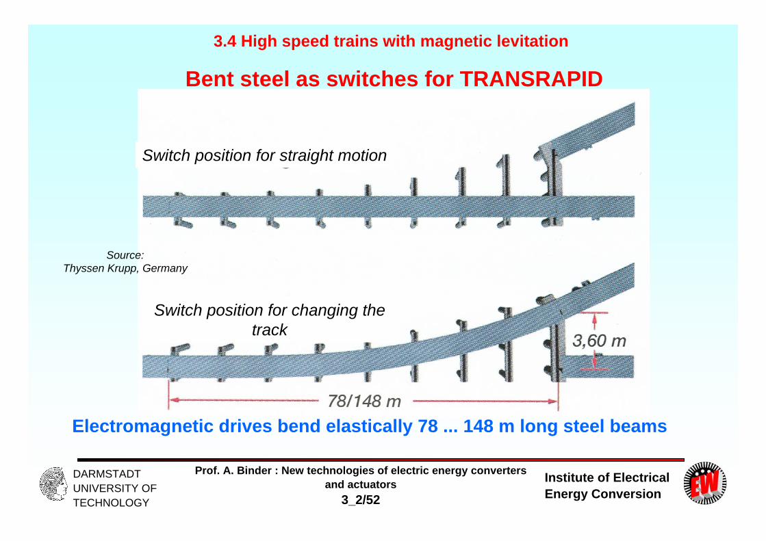
Bent steel as switches for TRANSRAPID
Electromagnetic drives bend elastically 78 ... 148 m long steel beams
3.4 High speed trains with magnetic levitation
Source: Thyssen Krupp, Germany
Switch position for straight motion
Switch position for changing the track
Institute of Electrical Energy Conversion
Prof. A. Binder : New technologies of electric energy convertersand actuators
3_2/53
DARMSTADT UNIVERSITY OF TECHNOLOGY
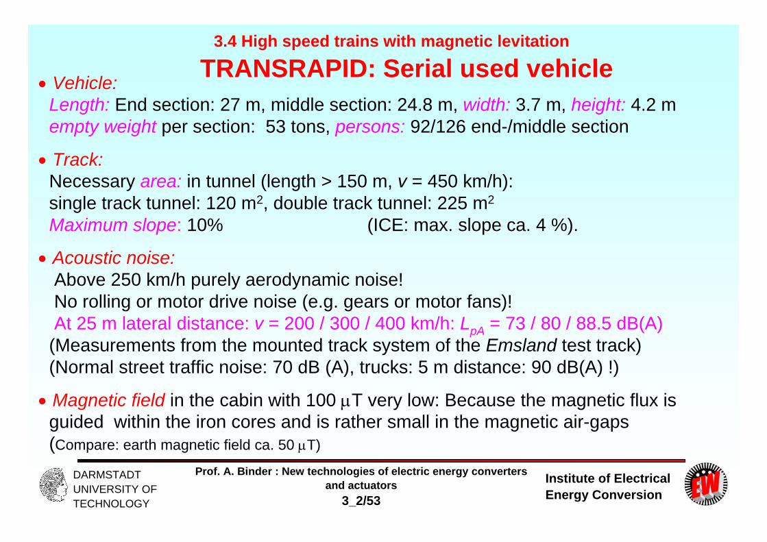
Vehicle:Length: End section: 27 m, middle section: 24.8 m, width: 3.7 m, height: 4.2 mempty weight per section: 53 tons, persons: 92/126 end-/middle section
Track:Necessary area: in tunnel (length > 150 m, v = 450 km/h):single track tunnel: 120 m2, double track tunnel: 225 m2
Maximum slope: 10% (ICE: max. slope ca. 4 %).
Acoustic noise:Above 250 km/h purely aerodynamic noise!No rolling or motor drive noise (e.g. gears or motor fans)!At 25 m lateral distance: v = 200 / 300 / 400 km/h: LpA = 73 / 80 / 88.5 dB(A)
(Measurements from the mounted track system of the Emsland test track)(Normal street traffic noise: 70 dB (A), trucks: 5 m distance: 90 dB(A) !)
Magnetic field in the cabin with 100 T very low: Because the magnetic flux is guided within the iron cores and is rather small in the magnetic air-gaps(Compare: earth magnetic field ca. 50 T)
3.4 High speed trains with magnetic levitation
TRANSRAPID: Serial used vehicle
Institute of Electrical Energy Conversion
Prof. A. Binder : New technologies of electric energy convertersand actuators
3_2/54
DARMSTADT UNIVERSITY OF TECHNOLOGY
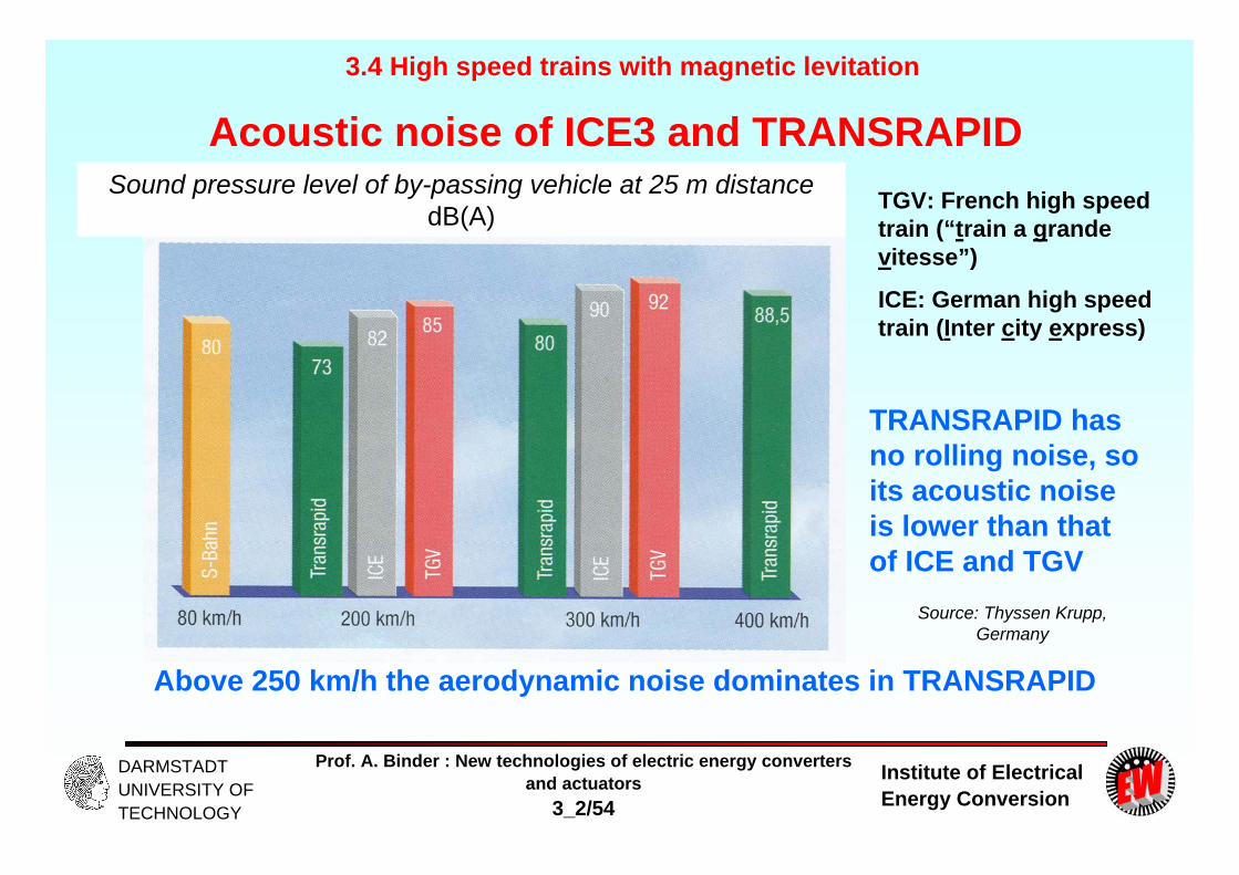
Acoustic noise of ICE3 and TRANSRAPIDTGV: French high speed train (“train a grandevitesse”)
ICE: German high speed train (Inter city express)
TRANSRAPID has no rolling noise, so its acoustic noise is lower than that of ICE and TGV
Above 250 km/h the aerodynamic noise dominates in TRANSRAPID
3.4 High speed trains with magnetic levitation
Source: Thyssen Krupp, Germany
Sound pressure level of by-passing vehicle at 25 m distance dB(A)

Institute of Electrical Energy Conversion
Prof. A. Binder : New technologies of electric energy convertersand actuators
3_2/55
DARMSTADT UNIVERSITY OF TECHNOLOGY
3.4 High speed trains with magnetic levitation
Comparison: Acoustic sound level of bypassing trains at 25 m distance
Acoustic sound level of bypassing trains in 25 m distance
Metro
Source: PhD Thesis Dr. Fürst, TU Berlin
Institute of Electrical Energy Conversion
Prof. A. Binder : New technologies of electric energy convertersand actuators
3_2/56
DARMSTADT UNIVERSITY OF TECHNOLOGY
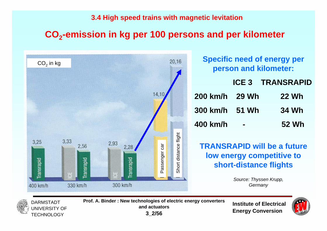
CO2-emission in kg per 100 persons and per kilometer
Specific need of energy per person and kilometer:
ICE 3 TRANSRAPID
200 km/h 29 Wh 22 Wh
300 km/h 51 Wh 34 Wh
400 km/h - 52 Wh
3.4 High speed trains with magnetic levitation
Source: Thyssen Krupp, Germany
TRANSRAPID will be a future low energy competitive to
short-distance flights
CO2 in kg
Pas
seng
er c
ar
Sho
rt di
stan
ce fl
ight

Institute of Electrical Energy Conversion
Prof. A. Binder : New technologies of electric energy convertersand actuators
3_2/57
DARMSTADT UNIVERSITY OF TECHNOLOGY
Comparison: Energy consumption per km & passenger3.4 High speed trains with magnetic levitation
w
Wh/(km*person)
with
1.5 persons
with
4 persons
Automotive vehicle
Modern railway
Source: PhD Thesis Dr. Fürst, TU Berlin

Institute of Electrical Energy Conversion
Prof. A. Binder : New technologies of electric energy convertersand actuators
3_2/58
DARMSTADT UNIVERSITY OF TECHNOLOGY
Need of area for the high speed track in m2 per m of vehicle length (inclusive substations)
3.4 High speed trains with magnetic levitation
Source: Thyssen Krupp, Germany
Surface level track
Mounted track
Institute of Electrical Energy Conversion
Prof. A. Binder : New technologies of electric energy convertersand actuators
3_2/59
DARMSTADT UNIVERSITY OF TECHNOLOGY
Summary: Active magnetically levitated high-speed train TRANSRAPID
- Synchronous long-stator linear motor at both sides of the track- Electromagnetic levitation with controlled air-gap- Motor secondary is also used as levitating magnet system- Up to 500 km/h until now feasible- Less energy consumption per person and km than competing air-plane- Well suited for long distance fast surface transport
New technologies of electric energy converters and New technologies of electric energy converters and actuatorsactuators

Institute of Electrical Energy Conversion
Prof. A. Binder : New technologies of electric energy convertersand actuators
3_2/60
DARMSTADT UNIVERSITY OF TECHNOLOGY
HSST – Magnetic railway
3.4 High speed trains with magnetic levitation
Source: Wikipedia: Maglev
Institute of Electrical Energy Conversion
Prof. A. Binder : New technologies of electric energy convertersand actuators
3_2/61
DARMSTADT UNIVERSITY OF TECHNOLOGY
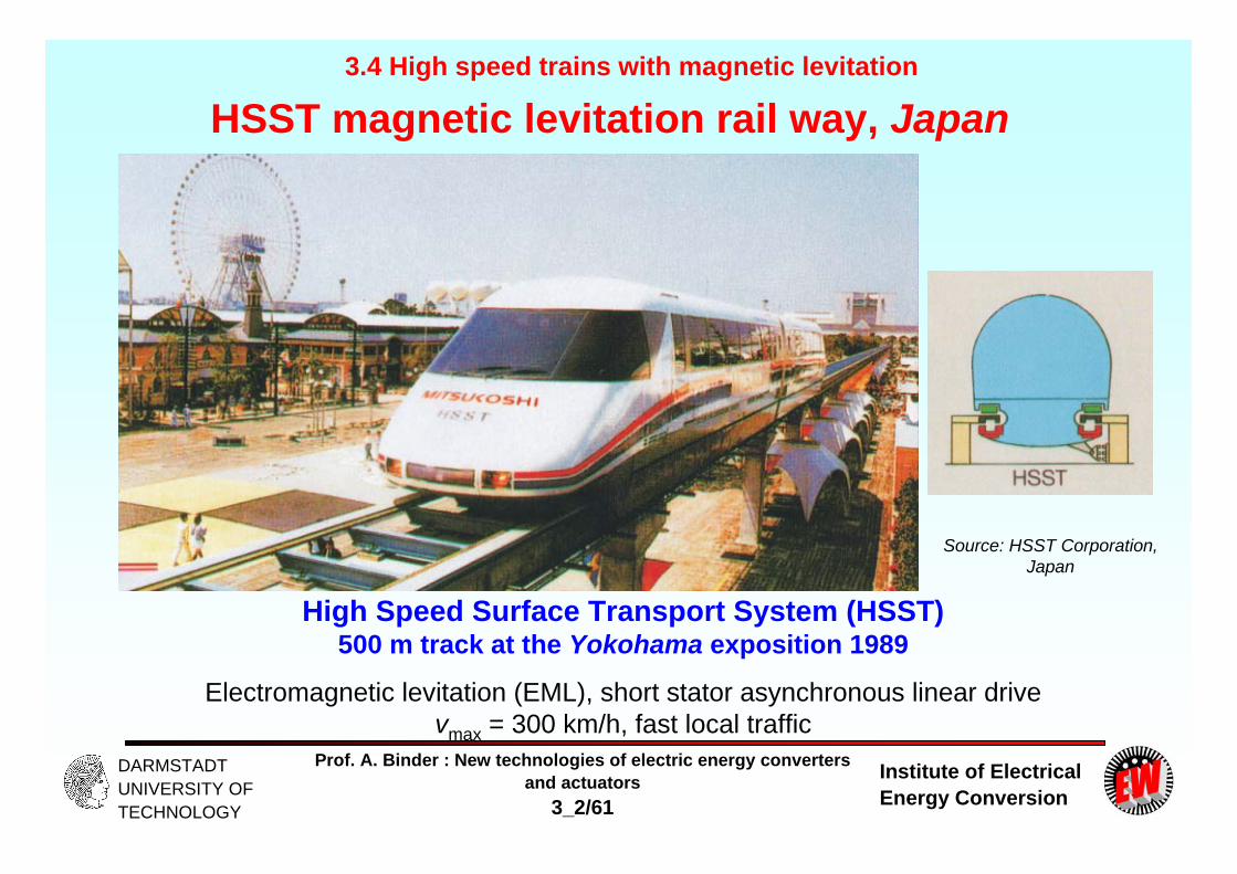
HSST magnetic levitation rail way, Japan
High Speed Surface Transport System (HSST)500 m track at the Yokohama exposition 1989
Electromagnetic levitation (EML), short stator asynchronous linear drivevmax = 300 km/h, fast local traffic
3.4 High speed trains with magnetic levitation
Source: HSST Corporation, Japan

Institute of Electrical Energy Conversion
Prof. A. Binder : New technologies of electric energy convertersand actuators
3_2/62
DARMSTADT UNIVERSITY OF TECHNOLOGY
HSST vehicle data
- Cheap short stator asynchronous linear drive on both sides with aluminum reaction rail as secondary
- Aluminum short stator three-phase windings
- Three-phase pantograph for stator current feeding limits maximum speed to vmax = 300 km/h; rigid aluminum conductor trolley
- 2-car train, 158 seats, 1.26 mio. passengers carried during 8 months, weight per car 15 tons
3.4 High speed trains with magnetic levitation
Source: HSST Corporation, Japan
Aluminum reaction rails
- DC magnets for levitation, 8 … 10 mm air gap
- Side stabilization via reluctance forces
- Gap sensors needed for gap control
Institute of Electrical Energy Conversion
Prof. A. Binder : New technologies of electric energy convertersand actuators
3_2/63
DARMSTADT UNIVERSITY OF TECHNOLOGY
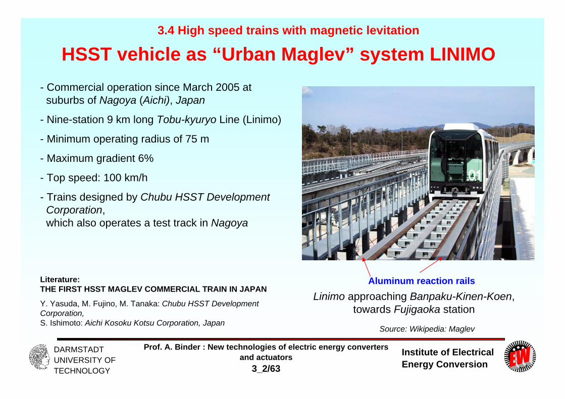
HSST vehicle as “Urban Maglev” system LINIMO- Commercial operation since March 2005 at
suburbs of Nagoya (Aichi), Japan
- Nine-station 9 km long Tobu-kyuryo Line (Linimo)
- Minimum operating radius of 75 m
- Maximum gradient 6%
- Top speed: 100 km/h
- Trains designed by Chubu HSST Development Corporation, which also operates a test track in Nagoya
3.4 High speed trains with magnetic levitation
Source: Wikipedia: Maglev
Aluminum reaction railsLinimo approaching Banpaku-Kinen-Koen,
towards Fujigaoka station
Literature: THE FIRST HSST MAGLEV COMMERCIAL TRAIN IN JAPAN
Y. Yasuda, M. Fujino, M. Tanaka: Chubu HSST Development Corporation, S. Ishimoto: Aichi Kosoku Kotsu Corporation, Japan

Institute of Electrical Energy Conversion
Prof. A. Binder : New technologies of electric energy convertersand actuators
3_2/64
DARMSTADT UNIVERSITY OF TECHNOLOGY
M-Bahn, Berlin
3.4 High speed trains with magnetic levitation
Source: Thyssen Krupp, Germany
Institute of Electrical Energy Conversion
Prof. A. Binder : New technologies of electric energy convertersand actuators
3_2/65
DARMSTADT UNIVERSITY OF TECHNOLOGY
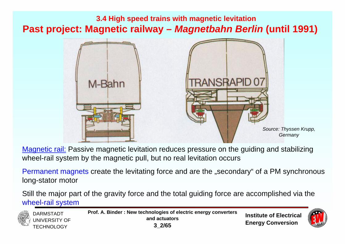
Past project: Magnetic railway – Magnetbahn Berlin (until 1991)
Magnetic rail: Passive magnetic levitation reduces pressure on the guiding and stabilizing wheel-rail system by the magnetic pull, but no real levitation occurs
Permanent magnets create the levitating force and are the „secondary“ of a PM synchronous long-stator motor
Still the major part of the gravity force and the total guiding force are accomplished via the wheel-rail system
3.4 High speed trains with magnetic levitation
Source: Thyssen Krupp, Germany
Institute of Electrical Energy Conversion
Prof. A. Binder : New technologies of electric energy convertersand actuators
3_2/66
DARMSTADT UNIVERSITY OF TECHNOLOGY
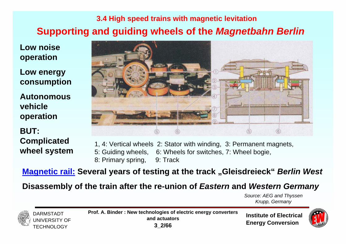
Supporting and guiding wheels of the Magnetbahn Berlin
Magnetic rail: Several years of testing at the track „Gleisdreieck“ Berlin West
Disassembly of the train after the re-union of Eastern and Western Germany
3.4 High speed trains with magnetic levitation
Source: AEG and ThyssenKrupp, Germany
Low noise operation
Low energy consumption
Autonomous vehicle operation
BUT: Complicated wheel system
1, 4: Vertical wheels 2: Stator with winding, 3: Permanent magnets, 5: Guiding wheels, 6: Wheels for switches, 7: Wheel bogie, 8: Primary spring, 9: Track