Embed Size (px)
Citation preview

ELECTRIC DRIVES
CONVERTERS IN ELECTRIC DRIVE SYSTEMSMODULE 2
Dr. Nik Rumzi Nik IdrisDept. of Energy Conversion, UTM
2009

CONVERTERS - Module 2
AC-DC controlled rectifier approximate model SIMULINK examples open-loop closed-loop
Switch Mode DC-DC converter2-Q and 4-Q converters Small signal modeling unipolar bipolarSIMULINK example
Current-controlled for SM convertersBridge converter hysteresis fixed frequency3-phase VSI hysteresis PI controller

Current-Controlled Converters
Current need to be controlled (in drives):
To control the torque To limit the current – protect the switching devices
Motor
Example of current control in cascade control structure
converterspeed
controllerposition
controller
+*
1/s
+ +
current
controller
T**
kTKt

Current-Controlled Converters
ON-OFF Controllers Separated PWM block
Hysteresis
Non-linearcontrollers
PI controllers
Linearcontrollers

Current-Controlled Converters
iref
+
Vdc
−
ia
ia
va
+
Va
ierr
ierr
q
q
Hysteresis-based

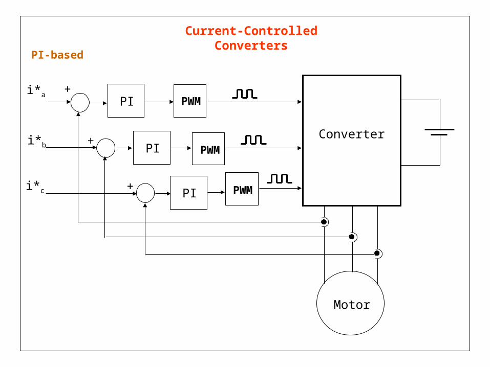
Current-Controlled Converters
Hysteresis-based - extending to 3-phase system
Motor
+
+
+
i*a
i*b
i*c
Converter

Current-Controlled Converters
Hysteresis-based - extending to 3-phase system
• High bandwidth, simple implementation, insensitive to parameter variations
• Variable switching frequency – depending on operating conditions
• Instantaneous error for isolated neutral load can reach double the band
For isolated neutral load, ia + ib + ic = 0control is not totally independent
id
iq
is
hh
hh

Current-Controlled Converters
Hysteresis-based – simulink block
References
Hysteresiscomparators
VSILoad

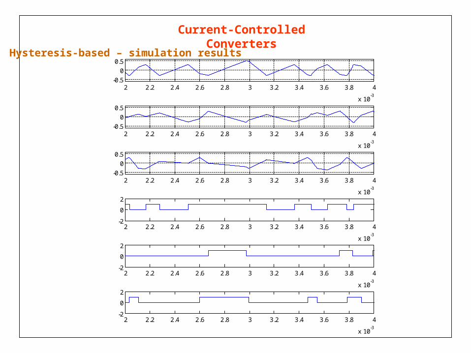
Current-Controlled Converters
Hysteresis-based – simulation results
-10 -5 0 5 10
-10
-5
0
5
10
0.005 0.01 0.015 0.02 0.025 0.03
-10
-5
0
5
10
Actual and reference currents Current error
Actual current locus
-0.5 -0.4 -0.3 -0.2 -0.1 0 0.1 0.2 0.3 0.4 0.5
-0.5
-0.4
-0.3
-0.2
-0.1
0
0.1
0.2
0.3
0.4
0.5
Current-Controlled Converters
Hysteresis-based – simulation results
2 2.2 2.4 2.6 2.8 3 3.2 3.4 3.6 3.8 4
x 10-3
-0.5
0
0.5
2 2.2 2.4 2.6 2.8 3 3.2 3.4 3.6 3.8 4
x 10-3
-0.5
0
0.5
2 2.2 2.4 2.6 2.8 3 3.2 3.4 3.6 3.8 4
x 10-3
-0.5
0
0.5
2 2.2 2.4 2.6 2.8 3 3.2 3.4 3.6 3.8 4
x 10-3
-2
0
2
2 2.2 2.4 2.6 2.8 3 3.2 3.4 3.6 3.8 4
x 10-3
-2
0
2
2 2.2 2.4 2.6 2.8 3 3.2 3.4 3.6 3.8 4
x 10-3
-2
0
2

Current-Controlled Converters
PI-based
vtri
Vdc
qvc
q
Vdc
Pulse widthmodulator
vc
Vdc
Pulse widthmodulator
vciref
PI+
q

Current-Controlled Converters
PI-based – extending to 3-phase
Motor
+
+
+
i*a
i*b
i*c
Converter
PWM
PWM
PWM
PWM
PWM
PWM
• Sinusoidal PWM
PI
PI
PI
• Interactions between phases only require 2 controllers• Tracking error

• Interactions between phases only require 2 controllers• Tracking error
Current-Controlled Converters
• Perform the control in synchronous frame - the current will appear as DC
• Perform the 3-phase to 2-phase transformation - only two controllers (instead of 3) are used
PI-based
Current-Controlled Converters
Motor
i*a
i*b
i*c
Converter
PWM
+
+
+
PWM
PWM
PI
PI
PI
PI-based

Current-Controlled Converters
Motor
i*a
i*b
i*c
Converter
3-2
3-2
SVM2-3
PI
PI
PI-based

Current-Controlled Converters
id*
iq*
PIcontroller
dqabc
abcdq
SVM or SPWM
VSIIM
va*
vb*
vc*
id
iq
+
+
PIcontroller
Synch speed estimator
s
s
PI-based

abc
sin_cosdq0
abc_to_dq0Transformation1
abc
sin_cosdq0
abc_to_dq0Transformation
v+-
Voltage Measurement
g
A
B
C
+
-
Universal Bridge
ia_s
To Workspace5
idref
To Workspace4
va
To Workspace1
Out1
Subsystem5
In1Out1
Subsystem3
Out1
Subsystem1
Step
Sine Wave2
Sine Wave1
Sine Wave
Series RLC Branch2
Series RLC Branch1
Series RLC Branch
Scope
Product2
Product1
Product
PID
PID Controller2
PID
PID Controller1
DC Voltage Sourcei+ -
Current Measurement2
i+ -
Current Measurement1
i+ -
Current Measurement
Current-Controlled Converters
Simulink and SimPowerSystems
References
32transformation
VSI 32transformation
PIcontrollers
Load
PI-based – simulation with control in stationary frame
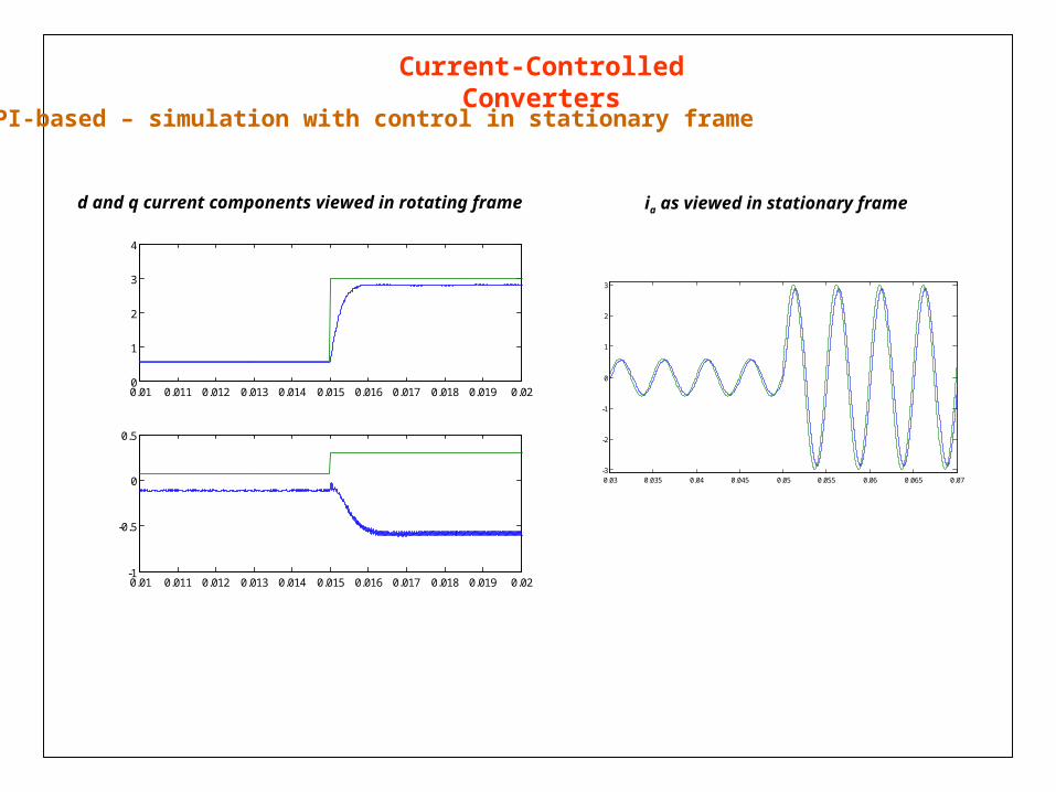
Current-Controlled Converters
d and q current components viewed in rotating frame ia as viewed in stationary frame
PI-based – simulation with control in stationary frame
0.01 0.011 0.012 0.013 0.014 0.015 0.016 0.017 0.018 0.019 0.020
1
2
3
4
0.01 0.011 0.012 0.013 0.014 0.015 0.016 0.017 0.018 0.019 0.02-1
-0.5
0
0.5
0.03 0.035 0.04 0.045 0.05 0.055 0.06 0.065 0.07-3
-2
-1
0
1
2
3
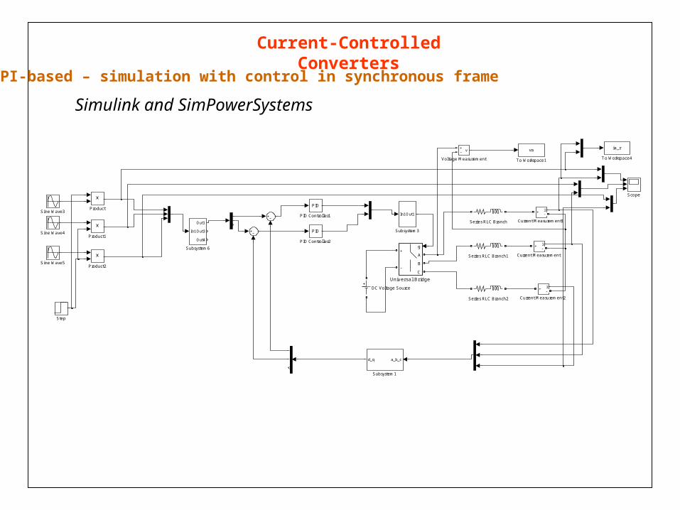
Current-Controlled Converters
Simulink and SimPowerSystems
PI-based – simulation with control in synchronous frame
v+-
Voltage Measurement
g
A
B
C
+
-
Universal Bridge
ia_r
To Workspace4
va
To Workspace1
In1
Out1
Out3
Out4
Subsystem6
In1Out1
Subsystem3
a_b_cd_q
Subsystem1
Step
Sine Wave5
Sine Wave4
Sine Wave3
Series RLC Branch2
Series RLC Branch1
Series RLC Branch
Scope
Product2
Product1
Product
PID
PID Controller2
PID
PID Controller1
DC Voltage Source i+ -
Current Measurement2
i+ -
Current Measurement1
i+ -
Current Measurement
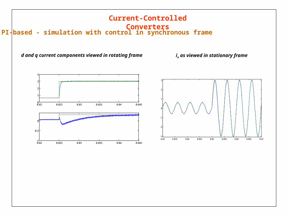
Current-Controlled Converters
PI-based - simulation with control in synchronous frame
d and q current components viewed in rotating frame ia as viewed in stationary frame
0.02 0.025 0.03 0.035 0.04 0.0450
1
2
3
4
0.02 0.025 0.03 0.035 0.04 0.045-1
-0.5
0
0.03 0.035 0.04 0.045 0.05 0.055 0.06 0.065 0.07-3
-2
-1
0
1
2
3