Embed Size (px)
Citation preview

New Technologies in Steel Buildings
Submission to the Canterbury Earthquakes Royal Commission
By Associate Professor G Charles CliftonMarch 13, 2012
ENG.CLI.0006A.1

2
Scope of Presentation
•
The earthquake series; timing and intensity•
Performance of existing steel buildings
•
General advice on achieving good performance•
Low damage steel solutions
•
Composite floor and heavy steel frame developments
•
Light steel frame developments•
Meeting other Building Code requirements
•
References
ENG.CLI.0006A.2

Christchurch Earthquake Series
Timing, Intensity, Expected Building Performance
ENG.CLI.0006A.3

4
The Earthquake Sequence: Impact on Christchurch CBD
Magnitude and Intensity of damaging events to date:4 Sept 2010: M 7.1, MM 7, ≈
0.7 x design*
26 Dec 2010: M 5.5?, MM 7 to 822 Feb 2011: M 6.3, MM 9 to 10, ≈
1.8 x design*
13 June, 2011: M 5.4?, MM 7 to 813 June 2011: M 6.3, MM 8 to 9, ≈
0.9 x design*
23 December 2011: M 5.5, MM 6 to 7, ≈
0.6 x design*
design* = design for ultimate limit state to current seismic loading standard
Cumulative effect ≡
close to maximum considered event in intensity and duration
ENG.CLI.0006A.4

5
Performance requirements of modern buildings in this level of event (>DLE)
For normal importance buildings to conventional ductile design, they:•Shall remain standing under DLE, should also under MCE•Structural and non structural damage will occur•Building will probably require replacement
ENG.CLI.0006A.5

Performance of Existing Multi-storey Steel Framed Buildings
ENG.CLI.0006A.6

7
Range of Buildings Affected
•
Ages from 1985 to 2010•
Number relatively low compared with precast concrete up to 2000; significant increase since then
•
Range in height from 3 to 22 storeys•
Systems used;–
Eccentrically braced frames (63%)
–
Moment resisting frames (50%)–
Shear walls (13%)
(some mixed systems hence > 100%)–
75% composite floors
–
25% precast concrete + topping floorsSee (Clifton et al, 2011)
ENG.CLI.0006A.7

8
Building Systems and Definitions: Moment Resisting Frame
Comprises beams and columns: •Rigid or semi-rigid connections (joints)•Rigid: beams first item to yield•Semi-rigid: connections first item to yield•Columns last item to yield in severe earthquake
ENG.CLI.0006A.8

9
Building Systems and Definitions: Eccentrically Braced FrameComprises active links, beams, braces and columns: •V braced or D braced•Active links first item to yield in earthquake•Columns last item to yield in severe earthquake
ENG.CLI.0006A.9

10
Building Systems and Definitions: Concentrically Braced FrameComprises collector beams, braces and columns: •V braced or X braced•Braces first item to buckle or yield in earthquake•Columns last item to yield in severe earthquake
ENG.CLI.0006A.10

11
Composite Floors
•
Assemblage of beams and column supporting floor slab
•
Typically beams simply supported off columns
•
Beams composite with concrete floor slab
•
See figure for terminology
ENG.CLI.0006A.11

12
Performance of Steel Framed Buildings in the Christchurch Earthquake Series•
Generally very good; minimal repair needed
•
Damage threshold higher than expected–
Damage threshold ≡
when structural repair is required
•
No significant changes to current design practice needed for conventional buildings
•
Current design practices readily adaptable to low damage solutions
•
Connections performed very well•
Poor details or low quality construction performed poorly–
Isolated examples only
–
Quality of construction generally very good
ENG.CLI.0006A.12

13
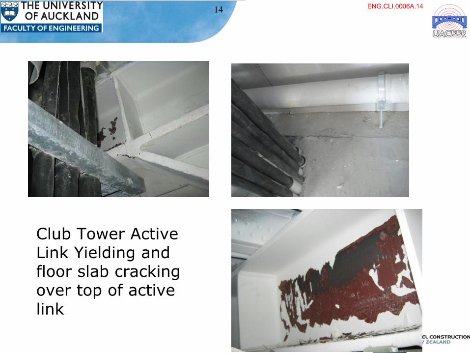
Case Study: Club Tower 12 storey mixed EBF and MRF, composite floors, torsionally irregular
•
Building has effectively self centred:–
45;35 mm out of plumb top; within construction tolerances
–
0.14% maximum residual deflection
•
Minimum damage–
Lift guide rail realignment required: this has cost approx $250k
–
No other structural or non structural repair or replacement needed
–
Building now fully occupied including CERA and CCC
–
The only (normal importance) high-rise building in Christchurch now in use
ENG.CLI.0006A.13
14
Club Tower Active Link Yielding and floor slab cracking over top of active link
ENG.CLI.0006A.14

15
Connections
•
When well designed and detailed, performed as intended–
No changes to design procedures required
–
First severe earthquake test of heavy bolted connections; excellent performance
•
Some failures due to poor design or detailing
•
Gusset plate connections: out of plane movement in endplates to column as intended
ENG.CLI.0006A.15

16
Pattern of Inelastic DemandAs intended for well detailed systems•Active link yielding in EBFs•No visible beam yielding in MRFs•Columns protected from inelastic demand
Less predictable for poorly detailed systems, eg•CBF brace weld fractures•EBF brace to beam fractures due to misalignment•Weld defect induced failures
ENG.CLI.0006A.16

17
Reasons for Good Performance
1. Good management and technical robustness–
Capacity design procedure accounts for whole system performance
–
Connection designs comprehensive and conservative•
Includes minimum forces on connections and splices
–
Continuous columns required in gravity and seismic- resisting systems
•
Assists with lateral stiffness and self-centering
ENG.CLI.0006A.17

18
Reasons for Good Performance2. Properties and quality of steel and steel construction
–
Steel has clearly defined yield point and only becomes inelastic under relatively high accelerations compared with concrete
–
Steels complying with NZS 3404 have good mechanical properties•
Continuous cast, controlled rolled
•
High ductility and charpy impact properties
•
Highly consistent yield and tensile strengths
–
Steel buildings generally well designed, detailed and constructed•
Not much independent inspection so industry must police the standards: this worked well in multi-storey buildings
ENG.CLI.0006A.18

19
Reasons for Good Performance
3. Excellent performance of composite floors–
Most robust of the floor systems in earthquake
–
More on this elsewhere in presentation
4.Good luck–
Capacity design procedure has accounted for whole system performance even with extra strengths from composite floor slabs that were not expressly accounted for in design; therefore
–
Overall system behaviour still as expected, but–
Inelastic demand lower than expected and
–
Damage threshold higher than expected
ENG.CLI.0006A.19

20
Excellent Performance of Composite FloorsThey have demonstrated:•Excellent diaphragm action•Excellent interconnection with frames•Elastic out of plane resistance (doubles strength and stiffness) which has self-centred conventional EBF/MRF systems •No repair required to any composite floor system in earthquakes
ENG.CLI.0006A.20
21
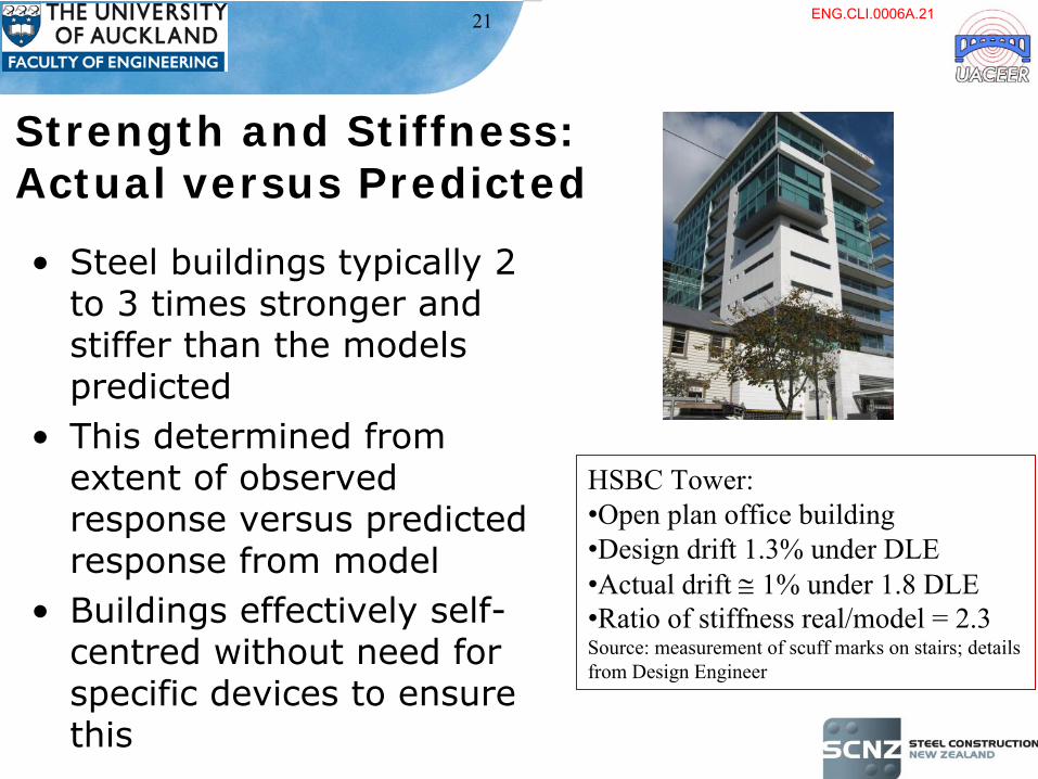
Strength and Stiffness: Actual versus Predicted
•
Steel buildings typically 2 to 3 times stronger and stiffer than the models predicted
•
This determined from extent of observed response versus predicted response from model
•
Buildings effectively self- centred without need for
specific devices to ensure this
HSBC Tower:•Open plan office building•Design drift 1.3% under DLE•Actual drift
1% under 1.8 DLE
•Ratio of stiffness real/model = 2.3Source: measurement of scuff marks on stairs; details from Design Engineer
ENG.CLI.0006A.21

22
Strength versus Stiffness: 10 Storey Building Transverse Direction •
Numerical modelling under 10 earthquake records
•
Floor slab precast TT with topping between frames
•
Without floor slab means as diaphragm
•
With floor slab means as TT with topping
Source (Lao, 2012)
ENG.CLI.0006A.22

23
Damage and Disruption to Contents and Non-Structural Components
•
Minimal in buildings that performed well–
most contents still in place
•
Proportional to observed inelastic drift–
more effects in buildings with higher drift (compare PWC and HSBC tower)
•
EBFs showed less damage than MRFs
•
Some effects of vertical acceleration seen, eg–
doors off hinges
ENG.CLI.0006A.23

24
Adequacy of Capacity Design Procedure
•
Objective: to concentrate inelastic response into selected components of the structure and suppress it in other components–
eg the active link in EBFs
•
Objective has been achieved–
Other components have remained elastic, despite
–
Structures being stronger than expected–
Upper limit shown to be adequate
ENG.CLI.0006A.24

Performance of Existing Light Steel Framed Buildings
ENG.CLI.0006A.25

26
LSF: Excellent performance•
Around 50 houses in strongly shaken areas
•
New construction (within last 10 years)
•
Typical construction comprises:–
Light steel frame walls, roof
–
Brick veneer cladding–
Long run steel roofing
•
In sites with good ground:–
One partially dislodged brick only damage reported (Darfield 09/2010)
–
No cracking of internal wall linings(Bruneau et al, 2010; Clifton et al, 2011)
Dislodged brick
ENG.CLI.0006A.26

General Advice on Maximising Damage Threshold in Multi-Storey Steel Framed Buildings
ENG.CLI.0006A.27

General Advice on Maximising Damage Threshold in Steel Buildings
•
Use composite concrete floor on steel deck on steel beam systems–
Long span solutions (up to 25m clear span)
–
Robust design procedures for fire, vibration, acoustic insulation
–
Fully tension all bolts in bolted connections to enhance out of plane strength and elastic stiffness
–
Promotes self-centering of the building
ENG.CLI.0006A.28

29
General Advice on Maximising Damage Threshold in Steel Buildings•
All columns continuous up full height of building–
Elastic columns aid self centering
–
Need moment resisting splices away from plastic hinge zone
•
Allow column base rotation without column hinging–
Semi-rigid or rigid base with endplate controlling moment capacity
–
Stepping or rocking bases
Combination of composite floor and elastic columns gives a linked elastic frame which promotes self-centering for rapid reoccupation
ENG.CLI.0006A.29

Low Damage Steel Building Solutions
ENG.CLI.0006A.30
31
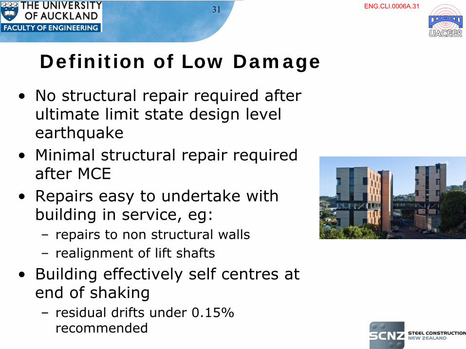
Definition of Low Damage
•
No structural repair required after ultimate limit state design level earthquake
•
Minimal structural repair required after MCE
•
Repairs easy to undertake with building in service, eg:–
repairs to non structural walls
–
realignment of lift shafts
•
Building effectively self centres at end of shaking–
residual drifts under 0.15% recommended
ENG.CLI.0006A.31

32
Format for Presentation of Each System•
Concept and details of system
•
Benefits and limitations•
Cost versus conventional construction–
Based approximately on the 4 storey building given next slide
–
The percentage differences are in the net cost of the structural system (ie frame, floors, roof), comprising approx. 25% total cost of building. Excludes foundations, cladding and fit-out
–
Also does not include benefits from speed of construction resulting in early occupation; these are typically greater than material cost differences
•
Status of design and detailing guidance•
Principal source of further information
ENG.CLI.0006A.32

33
Cost Comparison Building
•
Based on SCNZ study building see (SCNZ, 2012) for details
–
Concrete, steel, timber building options
–
Steel most cost-effective completed solution
•
4 storey, 5000 m2
total floor area
•
Screw piles into ground with concrete slab
•
Steel frame with MRFs and EBFs•
Composite floor system on trapezoidal decking–
1% more expensive book value than precast concrete floor, but
–
more dependable earthquake (and fire) performance and used as basis for conventional construction
ENG.CLI.0006A.33

34
Conventional MRFs and EBFs; Limits on Structural Ductility Factor, µ
•
Conventional EBFs, CBFs, MRFs with µactual
≤
2•
Benefit: well established
•
Limitations: not mechanism to force self centering but expected to dynamically self centre through linked elastic frame, comprising:–
Composite floor slab
–
Continuous columns in gravity and seismic resisting systems
•
Cost versus conventional: up to 2% greater•
Status: in-use
Design guidance: Feeney and Clifton, 2001 (HERA Report R4-76); SCNZ material
ENG.CLI.0006A.34

35
EBFs with Bolted Replaceable Active Links
•
Active links bolted in using MEP connections
•
Benefits: all the proven advantages of EBFs with easy link replacement if required
•
Limitations: none•
Cost versus conventional: same
•
Status: now available through SCNZ and recommended for new EBF systems
Design guidance: SCNZ; HERA Report R4-76 update on EBFs due mid 2012
Indicative Detail
ENG.CLI.0006A.35

36
EBFs with Rotational Bolted Active Links•
Active link using slotted bolts and rotating plates
•
Benefits: no active link replacement required; only bolts if necessary need replacing
•
Cost versus conventional: within 1% estimated
•
Status: concept only; requires development through research
•
Uses lessons learned from SCSHJ development–
Uses symmetric not asymmetric friction sliding
(Khan and Clifton, 2011)
ENG.CLI.0006A.36

37
MRFs with Flange Bolted Joints
•
MRF with semi-rigid connections•
Benefits: established, decouples strength and stiffness; allows long span beams
•
Limitations: low seismic zones and µ
≤
2 only
•
Cost versus conventional: same or slightly cheaper
•
Status: in-use, eg University of Auckland 2 major buildings
Design guidance: Clifton, 2005/2007; SCNZ material
Owen G Glenn Building, UofA
ENG.CLI.0006A.37

38
MRFs with Sliding Hinge Joints•
MRFs with asymmetric friction sliding semi-rigid connections for high ductility demand
•
Benefits: established, decouples strength and stiffness, allows long span beams, slab isolation, no beam or column damage, good self-
centering (especially with composite floor system)
•
Limitations: some loss of initial stiffness after severe shaking (this is easily taken account of in design)
•
Cost versus conventional MRF: same•
Status: in use, eg. Te Puni village, Victoria University
Design guidance: Clifton, 2005/2007; Hsen-Han Khoo, 2011sacrificialposition bolts
bottom flange bolts
beamcolumn
ENG.CLI.0006A.38

39
MRFs with Self Centering Sliding Hinge Joint
•
SHJ with dynamic self centering and restoration of stiffness after severe shaking
•
Cost versus conventional: approx 2 -
5 % greater
•
Status: under development, due end 2012
•
Put dynamic system on eg end columns only in frame to gain benefit, reduce cost
Hsen-Han Khoo, 2011; HHK thesis expected 2013
ENG.CLI.0006A.39

40
SCSHJ: Results
•
Increasing flag shaped moment-rotation behaviour with Ring Springs
better self-
centering•
Very limited floor
slab damage
-2.5-2
-1.5-1
-0.50
0.51
1.52
2.5
-35 -30 -25 -20 -15 -10 -5 0 5 10 15 20 25 30 35
M/M
des
Rotation (mrad)
SHJPR=40.2%PR=52.6%
4 cycles > 2% drift 32 cycles > 2% drift
ENG.CLI.0006A.40

41
CBFs with Uplifting Columns•
CBF with the columns allowed to uplift once tension load exceeds a pre-set limit; braces designed for actions from uplifted system at DLE displacement
•
Benefits: all members elastic at DLE•
Limitations: floor slab resistance to uplift must be included; column base shear maintained
•
Cost versus conventional CBF: 2 to 3% higher
•
Status: in-use
Designed to first principles in accordance with
NZS 3404; ring springs guidance (Clifton, 2005/2007)
ENG.CLI.0006A.41

42
CBFs with Buckling Restrained Braces•
Braces comprise yielding core encased to prevent bucking in compression
•
Benefits: delivers same strength and stiffness in tension and compression, so–
Can match capacity to demand closely
–
Stiff system, no build-up in inelastic drift–
Use with elastic frame and composite floor slab to enhance self centering
–
Excellent for retrofitting existing buildings
•
Limitations: brace manufacture more complex
•
Cost versus conventional; 2% more?•
Status: NZ based generic detail now experimentally tested; design and detailing procedure available
•
Wijanto, 2012; SCNZ, 2011; HERA Report R4-76
ENG.CLI.0006A.42

43
Low Damage Systems: CBFs with Sliding Braces
•
AFC application to CBF system under development at Uni. of Canterbury
•
Small scale testing completed•
Frame testing 2012
•
Likely benefits: similar to BRB•
Cost versus conventional: likely very similar
•
Design guidance 2012
(Golodrino et al, 2012a)
P
3.0 m
Laboratory Frame Model
Dynamic Testing on AFC
connection
ENG.CLI.0006A.43

44
H2FV Viscous Dampers •
Developed at University of Canterbury 2010
•
High capacity, small size viscous damper
•
Needs further development work before suitable for seismic rates of loading
•
Potential application in wide range of steel and concrete framed seismic-
resisting systems
(Golodrino et al, 2012b)
ENG.CLI.0006A.44
45
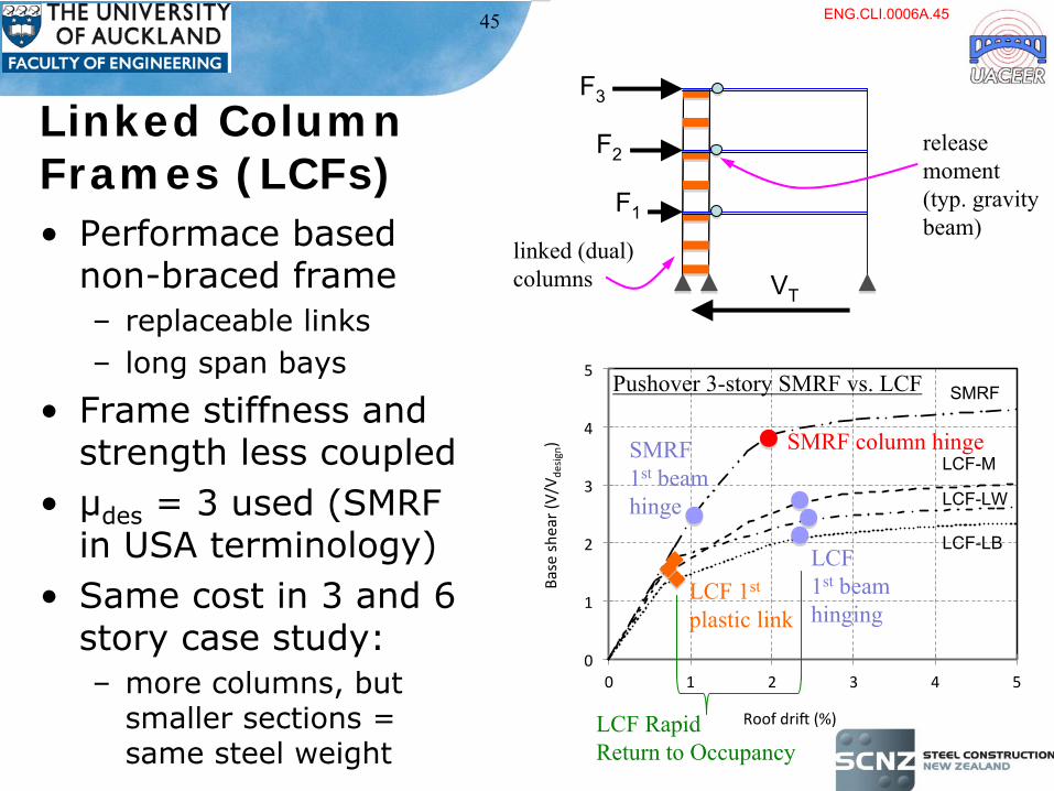
Linked Column Frames (LCFs)•
Performace based non-braced frame–
replaceable links
–
long span bays
•
Frame stiffness and strength less coupled
•
µdes
= 3 used (SMRF in USA terminology)
•
Same cost in 3 and 6 story case study:–
more columns, but smaller sections = same steel weight
VT
SMRF
LCF-M
LCF-LB
LCF-LW
release
moment(typ. gravity
beam)linked (dual)columns
Pushover 3-story SMRF vs. LCF
LCF 1st
plastic link
LCF
1st
beamhinging
SMRF1st
beamhinge
LCF RapidReturn to Occupancy
SMRF column hinge
F1
F2
F3
ENG.CLI.0006A.45

46
Protect gravity system including columns; i.e. no hinging at any column bases
•gravity columns ‘pinned’•linked columns ‘pinned’, with rigidity
provided by base link
Self-centering ability;•upon removal of damaged links, residual stiffness of frame
re-centers the building•frame is stable during this process•aftershocks will assist re-
centering
Cost effective beam-column;•connections detailed as fully elastic not overstrength based due to no inelastic demand at rapid return and low inelastic demands at collapse prevention levels
LCF Benefits 9.1m 9.1m 9.1m9.1m1.2m
1.2m
4m4m
4m4m
4m4m
ENG.CLI.0006A.46

47
LCF Replaceable Links
•
Full scale linked column replaceable link tests:–
p
to 9% rad (ie shear active link)
–
short and long links
•
More information:–
Dusicka et al (2012) STESSA –
design guides
–
Berman et al (in review) Eng. Structures –
time
history analysis–
Dusicka et al (2010) 9USN/10CCEE –
replacable links
-450
-300
-150
0
150
300
450
-2000-1500-1000-500
0500
100015002000
-0.15 -0.1 -0.05 0 0.05 0.1 0.15
Link
She
ar, V
(kip
)
Lin
k Sh
ear,
V (k
N)
Inelastic Rotation, γp (rad)
LCF material courtesy of Peter Dusicka, University of Portland, USA
ENG.CLI.0006A.47

48
Steel Shear Walls•
Current design uses thin plate tension field action in conjunction with a MRF;
•
Based principally on Canadian and U.S. research and implementations
•
Design/detailing guidance–
Ductile Design of Steel Structures (Bruneau et al, 2011)
–
AISC Design Guide 20 (AISC, 2007)
•
Status: in use, SCNZ design guidance–
(Fussell, 2009)
ENG.CLI.0006A.48

49
Steel Plate Shear Walls
•
Benefits: –
High stiffness, strength, and ductility
–
Rapid construction using simple detailing–
Result in more leasable square-foot per floor than for other systems (e.g. concrete walls)
•
Limitations: –
Requires replacement of plates following severe earthquake (fuse analogy)
•
Cost versus conventional construction–
Comparable (cheaper detailing, larger beams/columns)
–
Cheaper for given drift
ENG.CLI.0006A.49

50
UB NewZ-BREAKSS
Top Story Displacement (in)
Top Story Drift (%)
Bas
e Sh
ear
(kip
s)
NewZ-BREAKSS HysteresisFull Infill Plates
-5
-3.4
-4
-2.7
-3
-2.0
-2
-1.4
-1
-0.7
0
0.0
1
0.7
2
1.4
3
2.0
4
2.7
5
3.4
-60-50-40-30-20-10
0102030405060
-5
-3.4
-4
-2.7
-3
-2.0
-2
-1.4
-1
-0.7
0
0.0
1
0.7
2
1.4
3
2.0
4
2.7
5
3.4
-60-50-40-30-20-10
0102030405060
0.167y0.33y0.67 y1.0y2y3y
4y2% drift2.5% drift3% drift
•
Self-centering Steel Plate Shear Walls without beam-growth (theoretical and experimental results 2011-12)
Courtesy of Michel Bruneau, University at Buffalo
ENG.CLI.0006A.50

51
Steel Shear Walls: NZ Research
•
Proposed development of a stepping shear wall with active self centering; PhD project commencing 2012–
lighter construction
–
active self centering–
target low to medium rise buildings
ENG.CLI.0006A.51

52
Base Isolation •
Suited to stiff, strong, light superstructures, eg–
Steel MRFs with semi-rigid connections
–
CBF systems with distributing base beam
•
Composite floor system•
Relatively flat site
•
Low aspect ratio building (Height/width ≤
1)•
Soil classes B, C, D if careful
•
Reduces floor accelerations and hence damage and disruption to contents
•
Cost over conventional construction: 8 to 10 %
ENG.CLI.0006A.52

53
Other Solutions and Sources of Further Information•
See details in Chapter 8 of (Buchanan et al, 2011)
•
See also details in STESSA 2012 proceedings (Mazzolani and Herrera, 2012)
•
Excellent overview of steel’s performance in the Christchurch earthquakes and potential for the rebuilding is given in (SCNZ, 2012)
ENG.CLI.0006A.53

New Technologies for Composite Floor Systems and Heavy Steel Frames
ENG.CLI.0006A.54

55
Summary of New Technologies
•
All weather shear stud welding •
Long span beam with web openings
•
New steel decking systems•
Design for fire resistance with most support beams unprotected
Composite floor systems are the best performing system in these earthquakes. No repair required to any floor. They are stable at all stages of construction in aftershocks. Some major new advances are:
ENG.CLI.0006A.55

56
All Weather Shear Stud Welding•
Concrete slab made composite with supporting beams through shear studs welded through deck
•
This process is undertaken on site and typically exposed to weather
•
NZ companies pioneered all weather shear stud welding technology–
Can place studs in any weather including standing water
–
Record of weld quality each stud kept for inspection
–
Recognised by AS/NZS 1554.2
•
Now standard practice for NZ deck laying companies
ENG.CLI.0006A.56

57
Long Span Beams With Web Openings•
Two major fabricators provide this service–
Dixon and Haddon Ltd: Fabsec System
–
Grayson Engineering Ltd: Cellular beam System
•
Fabsec welds beams from plate
•
Cellular beams made from split and re-welded castellated hot rolled beams
•
Spans up to 25 metres•
I or box section beams
•
Depths up to 2m•
Flange thicknesses up to 100 mm
•
Optimised for strength and stiffness
For more information:
Fabsec: www.dhsteel.co.nzCellular: www.grayson-engineering.co.nz
ENG.CLI.0006A.57

58
New Steel Decking Systems•
All types shown opposite are available
•
Trapezoidal most common: in 60mm, 80mm and 100mm depths
•
Made from high strength steel to AS 1397, G550 with typically Z257 coating
•
Performance determined by comprehensive testing–
Static and high cycle dynamic–
Fire
For more info contact decking suppliers or SCNZ
Reinforcing mesh
65mm minimum
Fire emergency reinforcement
210mm Metal Deck
Reinforcing mesh
Clipped Pan Profile
Fire emergency reinforcement
Reinforcing mesh
Slab thickness
Trapezoidal (W) Profile
Reinforcing mesh
Joist
Light Steel Joist 75mm or 90mm
Negative reinforcement when required
(Comflor rib bars)
ENG.CLI.0006A.58

59
Design for Fire Resistance With Most Supporting Beams Unprotected
•
Slab Panel Method: design for dependable inelastic reserve of strength available from composite floor systems
•
Example of application shown opposite
•
Implements the tensile membrane model for slab behaviour (think of inverted dome: two way tension action and compression ring beam)
•
Current version published 2006–
SPM0306 software–
HERA Report R4-131:2006
•
Major new edition due 2012–
Software rewritten into more user-
friendly format
–
Significant enhancements to model•
More info: (Clifton GC, 2011)
ENG.CLI.0006A.59

60
Heavy Steel Frames: New Developments
•
Welded beams and columns including box columns
•
Designed and detailed standard connections for most applications backed by experimental testing and advanced numerical modelling (SCNZ, 2010)
•
Steel industry technical capability and capacity for the Christchurch rebuild (SCNZ, 2012)
ENG.CLI.0006A.60

Light Steel Frame New Developments
Summary and contact for further information only
ENG.CLI.0006A.61

62
LSF New Developments
•
Around 4% market share for houses
•
Up to 3 storeys now being built with lightweight and suspended concrete floors
•
Design guidance and standards now cover design, construction, durability
•
Excellent demonstrated performance in service and in earthquake and fire
•
Floor spans to 10 metres; portal frame spans to 40 metres
Source of more information:www.nashnz.org.nz
ENG.CLI.0006A.62

Meeting Other Building Code Requirements
ENG.CLI.0006A.63

64
NZBC Stipulates 7 Areas of Mandatory Building Performance: all must be met
•
Structural Stability–
earthquake is only one part
–
deflection limits–
in service vibration limits
•
Fire Safety•
Access
•
Moisture•
User Safety
•
Services and Facilities–
eg. airborne and impact sound
ENG.CLI.0006A.64

65
Performance of Steel Solutions in:
•
Fire:–
Commercial and retail multi-storey: if fire reaches full development likely to involve full floor at least
–
Fire severity very variable; building must cope with this without local or global collapse
–
Steel framed buildings with protected columns and composite floors very robust in fire and the only building system with whole building tested performance in fire
•
In service floor vibration:–
Can be critical in long span light weight floors ; good design solutions are available
•
Acoustics:–
Requires envelope solution for all floor system
–
Concrete only floors not suitable in new G6
ENG.CLI.0006A.65

66References 1 of 3
AISC (2007) Steel Plate Shear Walls (AISC Design Guide 20), American Institute of Steel Construction, Chicago, Illinois, 144 p.
Bruneau, M., Uang, C. M and Sabelli, R. 2011. Ductile Design of Steel Structures – Second Edition. McGraw-Hill Professional, New York, 921p.
Bruneau, M., Anagnostopoulou, M., MacRae, G., Clifton, C., & Fussell, A. (2010). Preliminary report on steel building damage from the Darfield earthquake of September 4, 2010. Bulletin of the New Zealand Society for Earthquake Engineering, 43(4), 351-359.
Buchanan, A.H., Bull, D., Dhakal, R., MacRae, G.A., Palermo, A and Pampanin, S. 2011. Base Isolation and Damage Resistant Technologies for Improved Seismic Performance of Buildings. University of Canterbury Research Report 2011 – 02. Christchurch, New Zealand
Clifton, G. C. (2011). Design of Composite Steel Floor Systems for Severe Fires: The Slab Panel Method: Presentation to The Steel in Fire Forum, UK,. In Steel in Fire Forum, UK, 20 September 2011 Meeting, Presentation No 1. [Downloadable slides in pdf format]. Steel in Fire Forum, UK. Retrieved from http://www.steelinfire.org.uk/
Clifton, G. C., Bruneau, M., MacRae, G. A., Leon, R., & Fussell, A. (2011). Steel Structures Damage from the Christchurch Earthquake Series of 2010 and 2011. New Zealand Society for Earthquake Engineering Bulletin, 44(4), 297-318. Retrieved from http://www.nzsee.org.nz/
Clifton, G. C. (2005/2007 update). Semi-Rigid Joints for Moment-Resisting Steel Framed Seismic-Resisting Systems. (PhD Thesis, The University of Auckland and HERA Report R4-134, with update 2007).
ENG.CLI.0006A.66

67References 2 of 3
Feeney, M. J., & Clifton, G. C. (2001). Seismic Design Procedures for Steel Structures including Tips on Seismic Design of Steel Structures: HERA Report on Seismic Design Procedures for Steel Structures. Manukau City, New Zealand: New Zealand Heavy Engineering Research Association.
Fussell, A., 2009. Design of Steel Plate Shear Walls. 2009. Steel Structures Seminar Series Spring 2009. Steel Construction New Zealand. Manukau City, New Zealand.
Golodrino, C.J., MacRae G. A., Chase, J.G., Rodgers, G.W., Munoz, A.M. and Clifton, G. C. 2012a. Design considerations for braced frames with asymmetrical friction connections - AFC. Proceedings of the 7th International Conference on Behaviour of Steel Structures in Seismically Active Areas. Santiago, Chile. 9 – 11 January, CRC Press.
Golodrino, C.J., Chase, J.G., Rodgers, G.W., MacRae G. A. and Clifton, G. C. 2012b. Force-displacement behaviour of HF2V dissipaters and possible applications on steel structures. Proceedings of the 7th International Conference on Behaviour of Steel Structures in Seismically Active Areas. Santiago, Chile. 9 – 11 January, CRC Press.
Hyland, C., Cowie, K., Bird, G. and Clifton G. C. 2010. Steel Connect: Structural Steelwork Connections Guide. Steel Construction New Zealand. Manukau City, New Zealand
Khan, M. H. and Clifton, G. C. (2011) Proposed Development of a Damage-Resisting Eccentrically Braced Frame with Rotational Active Links. New Zealand Society for Earthquake Engineering Bulletin, 44(2), 99 – 107
Khoo, H. H., Clifton, G. C., Butterworth, J., MacRae, G. A., & Ferguson, G. (2011). Influence of steel shim hardness on the Sliding Hinge Joint performance. Journal of Constructional Steel Research. doi:10.1016/j.jcsr.2011.11.009
ENG.CLI.0006A.67

68References 3 of 3
Khoo, H.H., Clifton, G.C., Butterworth, J., MacRae, G.A. & Mathieson, C.D. 2011. Development of the self-centering Sliding Hinge Joint. Ninth Pacific Conference of Earthquake Engineering. Auckland, New Zealand.
Khoo, H.H., Clifton, G.C., Butterworth, J. & MacRae, G.A. 2012. Shim and bolt size effect
on the asymmetric friction connection. Seventh STESSA Conference on Behaviour of Steel Structures in Seismic Areas. Santiago, Chile.
Lao, Y.P, 2012. Floor Slab Influence on the Seismic Behaviour of a Concentrically Braced Frame with Stepping Base. Master of Engineering Thesis. University of Auckland.
Mazzolani, F. and Herrera, R., editors. 2012. Proceedings of the 7th International Conference on Behaviour of Steel Structures in Seismically Active Areas. Santiago, Chile. 9 – 11 January, CRC Press.
NZS 3404: 1997/2001/2007. Steel Structures Standard, incorporating Amendments 1 and 2. Standards New Zealand. Wellington, New Zealand.
SCNZ. 2012. Steel: Proven Performer for a New Christchurch. Steel Construction New Zealand. Manukau City, New Zealand.
Wijanto, S.,2012. Behaviour and Design of Generic Buckling Restrained Brace Systems. Master of Engineering Thesis. University of Auckland.
ENG.CLI.0006A.68