Embed Size (px)
Citation preview
NEW RAILWAY BASE TUNNELS THROUGH THE EUROPEAN ALPS A. Busslinger1, Ch. Rudin2, P. Reinke3
1Dr.sc.nat., M.Sc. (geophys.),
2M.Sc. (phys.), M.Sc. (el. eng.),
3Dr.sc.tech., M.Sc. (mech.
eng.), HBI Haerter Ltd., Berne, Switzerland [email protected], [email protected], [email protected]
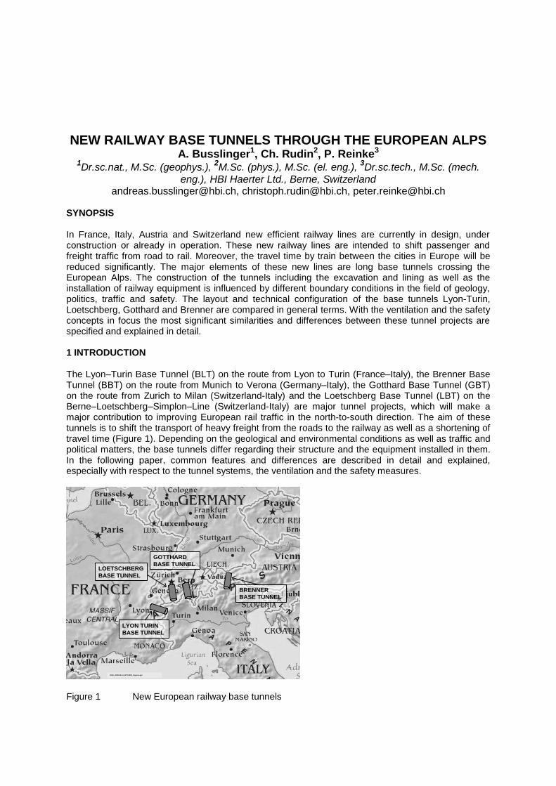
SYNOPSIS In France, Italy, Austria and Switzerland new efficient railway lines are currently in design, under construction or already in operation. These new railway lines are intended to shift passenger and freight traffic from road to rail. Moreover, the travel time by train between the cities in Europe will be reduced significantly. The major elements of these new lines are long base tunnels crossing the European Alps. The construction of the tunnels including the excavation and lining as well as the installation of railway equipment is influenced by different boundary conditions in the field of geology, politics, traffic and safety. The layout and technical configuration of the base tunnels Lyon-Turin, Loetschberg, Gotthard and Brenner are compared in general terms. With the ventilation and the safety concepts in focus the most significant similarities and differences between these tunnel projects are specified and explained in detail. 1 INTRODUCTION The Lyon–Turin Base Tunnel (BLT) on the route from Lyon to Turin (France–Italy), the Brenner Base Tunnel (BBT) on the route from Munich to Verona (Germany–Italy), the Gotthard Base Tunnel (GBT) on the route from Zurich to Milan (Switzerland-Italy) and the Loetschberg Base Tunnel (LBT) on the Berne–Loetschberg–Simplon–Line (Switzerland-Italy) are major tunnel projects, which will make a major contribution to improving European rail traffic in the north-to-south direction. The aim of these tunnels is to shift the transport of heavy freight from the roads to the railway as well as a shortening of travel time (Figure 1). Depending on the geological and environmental conditions as well as traffic and political matters, the base tunnels differ regarding their structure and the equipment installed in them. In the following paper, common features and differences are described in detail and explained, especially with respect to the tunnel systems, the ventilation and the safety measures.
LYON TURIN
BASE TUNNEL
BRENNER
BASE TUNNEL
LOETSCHBERG
BASE TUNNEL
GOTTHARD
BASE TUNNEL
DOK_2008-06-24_WTC2008_Figures.ppt
LYON TURIN
BASE TUNNEL
BRENNER
BASE TUNNEL
LOETSCHBERG
BASE TUNNEL
GOTTHARD
BASE TUNNEL
DOK_2008-06-24_WTC2008_Figures.ppt Figure 1 New European railway base tunnels
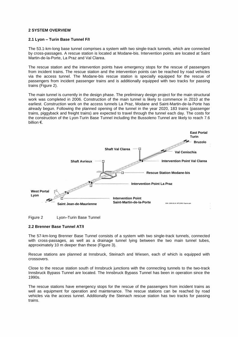
2 SYSTEM OVERVIEW 2.1 Lyon – Turin Base Tunnel F/I The 53.1-km-long base tunnel comprises a system with two single-track tunnels, which are connected by cross-passages. A rescue station is located at Modane-bis. Intervention points are located at Saint Martin-de-la-Porte, La Praz and Val Clarea. The rescue station and the intervention points have emergency stops for the rescue of passengers from incident trains. The rescue station and the intervention points can be reached by road vehicles via the access tunnel. The Modane-bis rescue station is specially equipped for the rescue of passengers from incident passenger trains and is additionally equipped with two tracks for passing trains (Figure 2). The main tunnel is currently in the design phase. The preliminary design project for the main structural work was completed in 2006. Construction of the main tunnel is likely to commence in 2010 at the earliest. Construction work on the access tunnels La Praz, Modane and Saint-Martin-de-la-Porte has already begun. Following the planned opening of the tunnel in the year 2020, 183 trains (passenger trains, piggyback and freight trains) are expected to travel through the tunnel each day. The costs for the construction of the Lyon-Turin Base Tunnel including the Bussoleno Tunnel are likely to reach 7.6 billion €.
Shaft Avrieux
Intervention Point La Praz
Saint Jean-de-Maurienne
West Portal
LyonIntervention Point
Saint-Martin-de-la-Porte
Shaft Val Clarea
Rescue Station Modane-bis
Intervention Point Val Clarea
Val Cenischia
East Portal
Turin
Bruzolo
DOK_2008-06-24_WTC2008_Figures.ppt
Shaft Avrieux
Intervention Point La Praz
Saint Jean-de-Maurienne
West Portal
LyonIntervention Point
Saint-Martin-de-la-Porte
Shaft Val Clarea
Rescue Station Modane-bis
Intervention Point Val Clarea
Val Cenischia
East Portal
Turin
Bruzolo
DOK_2008-06-24_WTC2008_Figures.ppt
Figure 2 Lyon–Turin Base Tunnel 2.2 Brenner Base Tunnel AT/I The 57-km-long Brenner Base Tunnel consists of a system with two single-track tunnels, connected with cross-passages, as well as a drainage tunnel lying between the two main tunnel tubes, approximately 10 m deeper than these (Figure 3). Rescue stations are planned at Innsbruck, Steinach and Wiesen, each of which is equipped with crossovers. Close to the rescue station south of Innsbruck junctions with the connecting tunnels to the two-track Innsbruck Bypass Tunnel are located. The Innsbruck Bypass Tunnel has been in operation since the 1990s. The rescue stations have emergency stops for the rescue of the passengers from incident trains as well as equipment for operation and maintenance. The rescue stations can be reached by road vehicles via the access tunnel. Additionally the Steinach rescue station has two tracks for passing trains.
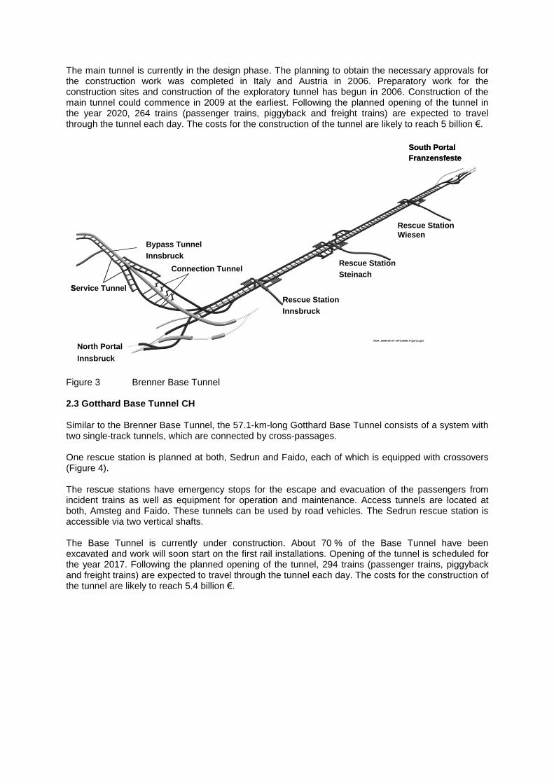
The main tunnel is currently in the design phase. The planning to obtain the necessary approvals for the construction work was completed in Italy and Austria in 2006. Preparatory work for the construction sites and construction of the exploratory tunnel has begun in 2006. Construction of the main tunnel could commence in 2009 at the earliest. Following the planned opening of the tunnel in the year 2020, 264 trains (passenger trains, piggyback and freight trains) are expected to travel through the tunnel each day. The costs for the construction of the tunnel are likely to reach 5 billion €.
North Portal
Innsbruck
South Portal
Franzensfeste
Bypass Tunnel
Innsbruck
Service Tunnel
Rescue Station
Innsbruck
Rescue Station
Steinach
Rescue Station
Wiesen
Connection Tunnel
DOK_2008-06-24_WTC2008_Figures.ppt
North Portal
Innsbruck
South Portal
Franzensfeste
Bypass Tunnel
Innsbruck
Service Tunnel
Rescue Station
Innsbruck
Rescue Station
Steinach
Rescue Station
Wiesen
Connection Tunnel
DOK_2008-06-24_WTC2008_Figures.ppt
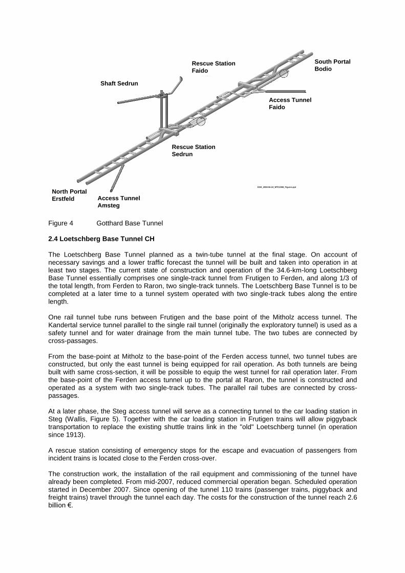
Figure 3 Brenner Base Tunnel 2.3 Gotthard Base Tunnel CH Similar to the Brenner Base Tunnel, the 57.1-km-long Gotthard Base Tunnel consists of a system with two single-track tunnels, which are connected by cross-passages. One rescue station is planned at both, Sedrun and Faido, each of which is equipped with crossovers (Figure 4). The rescue stations have emergency stops for the escape and evacuation of the passengers from incident trains as well as equipment for operation and maintenance. Access tunnels are located at both, Amsteg and Faido. These tunnels can be used by road vehicles. The Sedrun rescue station is accessible via two vertical shafts. The Base Tunnel is currently under construction. About 70 % of the Base Tunnel have been excavated and work will soon start on the first rail installations. Opening of the tunnel is scheduled for the year 2017. Following the planned opening of the tunnel, 294 trains (passenger trains, piggyback and freight trains) are expected to travel through the tunnel each day. The costs for the construction of the tunnel are likely to reach 5.4 billion €.
Rescue Station
Sedrun
Rescue Station
Faido
Access Tunnel
Amsteg
Shaft Sedrun
Access Tunnel
Faido
North Portal
Erstfeld
South Portal
Bodio
DOK_2008-06-24_WTC2008_Figures.ppt
Rescue Station
Sedrun
Rescue Station
Faido
Access Tunnel
Amsteg
Shaft Sedrun
Access Tunnel
Faido
North Portal
Erstfeld
South Portal
Bodio
DOK_2008-06-24_WTC2008_Figures.ppt
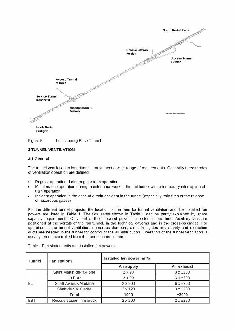
Figure 4 Gotthard Base Tunnel 2.4 Loetschberg Base Tunnel CH The Loetschberg Base Tunnel planned as a twin-tube tunnel at the final stage. On account of necessary savings and a lower traffic forecast the tunnel will be built and taken into operation in at least two stages. The current state of construction and operation of the 34.6-km-long Loetschberg Base Tunnel essentially comprises one single-track tunnel from Frutigen to Ferden, and along 1/3 of the total length, from Ferden to Raron, two single-track tunnels. The Loetschberg Base Tunnel is to be completed at a later time to a tunnel system operated with two single-track tubes along the entire length. One rail tunnel tube runs between Frutigen and the base point of the Mitholz access tunnel. The Kandertal service tunnel parallel to the single rail tunnel (originally the exploratory tunnel) is used as a safety tunnel and for water drainage from the main tunnel tube. The two tubes are connected by cross-passages. From the base-point at Mitholz to the base-point of the Ferden access tunnel, two tunnel tubes are constructed, but only the east tunnel is being equipped for rail operation. As both tunnels are being built with same cross-section, it will be possible to equip the west tunnel for rail operation later. From the base-point of the Ferden access tunnel up to the portal at Raron, the tunnel is constructed and operated as a system with two single-track tubes. The parallel rail tubes are connected by cross-passages. At a later phase, the Steg access tunnel will serve as a connecting tunnel to the car loading station in Steg (Wallis, Figure 5). Together with the car loading station in Frutigen trains will allow piggyback transportation to replace the existing shuttle trains link in the "old" Loetschberg tunnel (in operation since 1913). A rescue station consisting of emergency stops for the escape and evacuation of passengers from incident trains is located close to the Ferden cross-over. The construction work, the installation of the rail equipment and commissioning of the tunnel have already been completed. From mid-2007, reduced commercial operation began. Scheduled operation started in December 2007. Since opening of the tunnel 110 trains (passenger trains, piggyback and freight trains) travel through the tunnel each day. The costs for the construction of the tunnel reach 2.6 billion €.
Rescue Station
Mitholz
Rescue Station
Ferden
Access Tunnel
Mitholz
Access Tunnel
Ferden
North Portal
Frutigen
South Portal Raron
DOK_2008-06-24_WTC2008_Figures.ppt
Service Tunnel
Kandertal
Rescue Station
Mitholz
Rescue Station
Ferden
Access Tunnel
Mitholz
Access Tunnel
Ferden
North Portal
Frutigen
South Portal Raron
DOK_2008-06-24_WTC2008_Figures.ppt
Service Tunnel
Kandertal
Figure 5 Loetschberg Base Tunnel 3 TUNNEL VENTILATION 3.1 General The tunnel ventilation in long tunnels must meet a wide range of requirements. Generally three modes of ventilation operation are defined:
Regular operation during regular train operation
Maintenance operation during maintenance work in the rail tunnel with a temporary interruption of train operation
Incident operation in the case of a train accident in the tunnel (especially train fires or the release of hazardous gases)
For the different tunnel projects, the location of the fans for tunnel ventilation and the installed fan powers are listed in Table 1. The flow rates shown in Table 1 can be partly explained by spare capacity requirements. Only part of the specified power is needed at one time. Auxiliary fans are positioned at the portals of the rail tunnel, in the technical caverns and in the cross-passages. For operation of the tunnel ventilation, numerous dampers, air locks, gates and supply and extraction ducts are needed in the tunnel for control of the air distribution. Operation of the tunnel ventilation is usually remote controlled from the tunnel control centre. Table 1 Fan station units and installed fan powers
Tunnel Fan stations Installed fan power [m
3/s]
Air supply Air exhaust
BLT
Saint Martin-de-la-Porte 2 x 90 3 x ±200
La Praz 2 x 90 3 x ±200
Shaft Avrieux/Modane 2 x 200 6 x ±200
Shaft de Val Clarea 2 x 120 3 x ±200
Total 1000 ±3000
BBT Rescue station Innsbruck 2 x 200 2 x ±250
Tunnel Fan stations Installed fan power [m
3/s]
Air supply Air exhaust
Rescue station Steinach 2 x 200 2 x ±250
Rescue station Wiesen 2 x 200 2 x ±250
Total 1200 ±1500
GBT
Rescue station Sedrun 2 x 200 2 x ±250
Rescue station Faido 2 x 200 2 x ±250
Total 800 ±1000
LBT
Access tunnel Mitholz 2 x 150
Emergency station Ferden 2 x 200 2 x ±250
Total 700 ±500
Key: ± refers to reversible fans, i.e. operation with air supply and extraction
4 OBJECTIVES AND OPERATION OF TUNNEL VENTILATION 4.1 Regular operation In regular operation, safe and reliable tunnel operation must be guaranteed. For this purpose, independent of the season and the frequency of trains in the tunnel, the air temperature in the tunnel must be maintained below a limit of maximum 35°C. The tunnel air is heated naturally owing to the heat emitted by the surrounding rock. The original rock temperature reaches 45°C to 50°C at individual points in the tunnel with maximum rock coverage. Additional heat is generated by the train traffic and the heat emitted from the technical equipment installed in the tunnel. In all tunnels, the tunnel air is generally cooled in the rail tunnel by the piston effect of the moving trains. If this train-related air-change is not sufficient particularly during hot summer months, the air in the tunnel is cooled additionally by the tunnel ventilation system (BBT, GBT) or by a cooling water system fixed along the rail tunnel (Lyon– Turin Base Tunnel). 4.2 Maintenance operation During downtime for maintenance work in the rail tunnel, the tunnel ventilation systems must be activated to ensure favourable climatic conditions conforming to occupational health requirements in the maintenance areas. With the operation of supply and extraction fans the air-exchange at maintenance areas in the rail tunnel is established. In this way sufficient air renewal can be ensured and the requirements regarding occupational health and safety can be met. There is no difference in the ventilation principle in the tunnels. In certain tunnels (BBT, LBT), the effect of ventilation is temporarily increased by rail tunnel gates. 4.3 Incident operation The stopping of a burning passenger or freight train in the tunnel is relevant to the design of the incident ventilation. For incident operation, the following main ventilation objectives must be met:
Ensuring a protected waiting area for train passengers in the event of a fire in the emergency stop (overpressure in the waiting area with the supply of air from outside)
Support of self-rescue of the train passengers along the emergency stop (extraction of smoke along the emergency stop area)
Safeguarding an evacuation route via the non-incident tube as part of an evacuation concept (prevention of smoke propagation into the non-incident tube)
Support of the self-rescue of the train passengers in the incident tube in the case of a train fire outside the emergency stop (influencing the propagation of the smoke in the vicinity of the fire)
Depending on whether the incident train stops at the emergency stop or outside the emergency stop in the tunnel the following ventilation cases may apply:
Train stop at the emergency stop: With supply and extraction of air by the incident ventilation system, conditions for self-rescue and evacuation are optimized. In all tunnel projects, fresh air is supplied from outside via the access tunnels to prevent the ingress of smoke in the train passengers’ waiting area. By extraction of the smoky air from the emergency stop, the propagation of smoke is minimized. The smoke extraction strategy differs depending on the tunnel project (LBT, BLT, GBT: extraction near to the fire by means of controllable dampers; BBT: by a single extraction point in the middle of the emergency stop).
Train stop outside the emergency stop: Fresh air is supplied to the non-incident tunnel to prevent smoke ingress into the non-incident tube during the escape of the train passengers. To facilitate self-rescue of the train passengers in the incident tube, the propagation of smoke near the fire is minimized. In BBT, GBT and LBT, appropriate operational measures are implemented to improve the conditions (maintenance of possible smoke stratification by reduction of the train speeds of non-incident trains in the incident tunnel). In the Lyon–Turin Base Tunnel, depending on the location of the fire on the incident train, the incident ventilation system is used to influence the smoke propagation additionally (directed displacement of smoke, thinning of smoke, minimization of the smoke propagation near the fire).
In the case of a stop of the incident train at one of the intervention points in the Lyon– Turin Base Tunnel, the waiting area is kept smoke-free by the supply of fresh air through the access tunnels. By simultaneous smoke extraction at the centre of the intervention point, the smoke propagation in the incident tunnel is minimized.
In the event of an incident train stop along the single-track section of the Loetschberg Base Tunnel, the entire service and safety tunnel system running parallel to the rail tube is protected against the ingress of smoke by the supply of fresh air.
5 TUNNEL SAFETY CONCEPTS 5.1 Safety Measures The main common safety measures of the tunnel projects include:
Separated single-track tunnels with opposite travel direction
Cross-passages connecting the single-track tubes at regular intervals
Emergency stops accessible in the two rail tubes (especially for incident passenger trains), that make allowance for emergency running of the trains
Lyon–Turin Base Tunnel: additional intervention points accessible from both rail tunnels for the stop of incident freight trains
Loetschberg Base Tunnel: service tunnel parallel to the single-track tunnel section, accessible by cross-passages
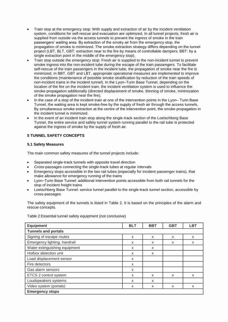
The safety equipment of the tunnels is listed in Table 2. It is based on the principles of the alarm and rescue concepts. Table 2 Essential tunnel safety equipment (not conclusive)
Equipment BLT BBT GBT LBT
Tunnels and portals
Signing of escape routes x x x x
Emergency lighting, handrail x x x x
Water extinguishing equipment x x
Hotbox detection unit x x
Load displacement sensor x
Fire detectors x
Gas alarm sensors x
ETCS 2 control system x x x x
Loudspeakers systems x x
Video system (portals) x x x x
Emergency stops
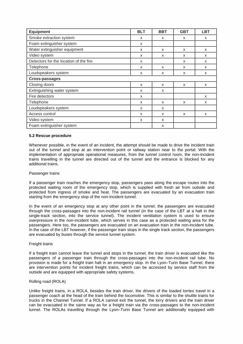
Equipment BLT BBT GBT LBT
Smoke extraction system x x x x
Foam extinguisher system x
Water extinguisher equipment x x x x
Video system x x x x
Detectors for the location of the fire x x x
Telephone x x x x
Loudspeakers system x x x x
Cross-passages
Closing doors x x x x
Extinguishing water system x x
Fire detectors x x
Telephone x x x x
Loudspeakers system x x
Access control x x x x
Video system x x
Foam extinguisher system x
5.2 Rescue procedure Whenever possible, in the event of an incident, the attempt should be made to drive the incident train out of the tunnel and stop at an intervention point or railway station near to the portal. With the implementation of appropriate operational measures, from the tunnel control room, the non-incident trains travelling in the tunnel are directed out of the tunnel and the entrance is blocked for any additional trains. Passenger trains If a passenger train reaches the emergency stop, passengers pass along the escape routes into the protected waiting room of the emergency stop, which is supplied with fresh air from outside and protected from ingress of smoke and heat. The passengers are evacuated by an evacuation train starting from the emergency stop of the non-incident tunnel. In the event of an emergency stop at any other point in the tunnel, the passengers are evacuated through the cross-passages into the non-incident rail tunnel (in the case of the LBT at a halt in the single-track section, into the service tunnel). The incident ventilation system is used to ensure overpressure in the non-incident tube, which serves in this case as a protected waiting area for the passengers. Here too, the passengers are evacuated on an evacuation train in the non-incident tube. In the case of the LBT however, if the passenger train stops in the single track section, the passengers are evacuated by buses through the service tunnel system. Freight trains If a freight train cannot leave the tunnel and stops in the tunnel, the train driver is evacuated like the passengers of a passenger train through the cross-passages into the non-incident rail tube. No provision is made for a freight train halt in an emergency stop. In the Lyon–Turin Base Tunnel, there are intervention points for incident freight trains, which can be accessed by service staff from the outside and are equipped with appropriate safety systems. Rolling road (ROLA) Unlike freight trains, in a ROLA, besides the train driver, the drivers of the loaded lorries travel in a passenger coach at the head of the train behind the locomotive. This is similar to the shuttle trains for trucks in the Channel Tunnel. If a ROLA cannot exit the tunnel, the lorry drivers and the train driver can be evacuated in the same way as for a freight train via the cross-passages to the non-incident tunnel. The ROLAs travelling through the Lyon–Turin Base Tunnel are additionally equipped with
diesel-powered systems for autonomous driving and for fast decoupling of the passenger coach from the rest of the train. This allows the coach to be driven independently out of the tunnel. The fire fighting in all the tunnels is carried out by the fire brigade on behalf of specially equipped fire extinguishing and rescue trains stationed close to the tunnel portals. The location of the incident is reached via the incident tube. 6 CONCLUSION The comparison of the civil and equipment-specific aspects of the major tunnel projects has revealed the following differences and common features. 6.1 General All base tunnels mentioned before have the following main characteristics in common:
The tunnel system consists of two single-track tunnels, connecting cross-passages, crossovers and rescue stations with emergency stops.
The gradient of the railway tunnels is small to enable both, high speed and high capacity train operation.
The operation concept foresees mixed traffic of passenger and freight trains. 6.2 Ventilation specific All base tunnels are equipped with efficient tunnel ventilation systems (e.g. cf. [1], [2]). The following main principles could be found:
The fan powers installed in the tunnels differ depending on the tunnel length and ventilation requirements.
New standards for railway tunnel ventilation (e.g. ventilation in rescue stations and cross-passages as well as the pressurisation of the non-incident tube) could be established within these projects.
The ventilation measures chosen have been evaluated during the commissioning phase of the Loetschberg base tunnel (cf. [1]).
The interaction of train operation, rescue scenarios and ventilation must be considered in the design of the tunnel ventilation systems.
Simple and therefore robust ventilation scenarios must be defined to admit a high reliability and safety in the tunnel system.
The ventilation design must be based not only on emergency but also on normal and maintenance operation of the tunnel system.
6.3 Safety specific The civil (e.g. rescue stations, cross-passages) and electromechanical (e.g. signing, video system, telephones) safety measures in the base tunnels are mainly identical. In addition, the following aspects may be highlighted:
The safety-relevant civil and equipment-related measures are based on the project specific alarm and rescue concepts for the tunnels.
There are differences in the design and location of the rescue stations in the tunnels of the specific projects.
The maximum distances between rescue stations or between portals and rescue stations respectively along the base tunnels is given by the typical rolling capability of an incident train.
Intervention stations in the tunnel especially for handling incident freight trains are only included in the Lyon–Turin Base Tunnel.
Beside technical and civil measures special interest must be drawn to the escape, rescue and intervention concept for the tunnel system.
7 REFERENCES [1] Rudin Ch., Busslinger A., Hagenah B., Nyfeler S., HBI Haerter Ltd., Switzerland, "Aerodynamics,
Climate and Ventilation of the Loetschberg Base Tunnel: First Results of the Measurements carried out during the Commissioning Phase", 4th International Conference ‘Tunnel Safety and Ventilation’ 2008, Graz
[2] Ferrazzini M., Rudin C., Shaha J., Galler R., “The current status of the tunnel ventilation design of the planned Brenner base tunnel between Austria and Italy” Risk reduction and safety in tunnelling projects, Torino, Italy, 2006
Andreas Busslinger graduated in Earth Sciences and Geophysics at the Swiss Federal Institute of Technology Zurich, Switzerland in 1994. He obtained a Ph.D. in Geophysics at the Swiss Federal Institute of Technology Zurich, Switzerland in 1998. Since 1999 he has been working for HBI Haerter Ltd. (Berne, Switzerland) as Project Manager and Principal Engineer specialised in Tunnel Ventilation, Tunnel Cooling, Tunnel Aerodynamics, Tunnel Thermodynamics and Tunnel Safety (e.g. Brenner, Gotthard, Ceneri and Loetschberg Base Tunnels).
Christoph Rudin graduated in Electrical Engineering at the Polytechnic of Brugg-Windisch, Switzerland in 1986. He obtained a Masters Degree in Physics at the University of Berne, Switzerland in 1994. Between 1986 and 1987 he was Development Engineer at Brown Boveri Ltd. In 1990 he joined Sprecher & Schuh Automation as Development Engineer. From 1992 to 1995 he worked for IBM Switzerland as Software Engineer. Since 1995 he has been working for HBI Haerter Ltd. (Berne, Switzerland) as Project Manager, Principal Engineer and Director (Board of Directors) specialised in Tunnel Ventilation, Aerodynamics and Safety (e.g. Brenner, Gotthard and Loetschberg Base Tunnels).
Peter Reinke graduated in Mechanical Engineering at the Technical University of Braunschweig, Germany in 1991. He obtained a Ph.D. in Mechanical Engineering at Swiss Federal Institute of Technology of Zurich, Switzerland in 1996. Since 1997 he has been working for HBI Haerter Ltd. (Berne, Switzerland) as Project Manager, Ventilation Engineer and Principal Engineer in the position of a Director (Board of Directors) specialised in Tunnel Ventilation, Tunnel Cooling, Tunnel Aerodynamics, Tunnel Thermodynamics, Mechanical Equipment and Tunnel Safety (e.g. Brenner, Gotthard and Loetschberg Base Tunnels).