Embed Size (px)
Citation preview
membranes
Review
New Perspectives on Fuel Cell Technology:A Brief Review
Norazlianie Sazali 1,* , Wan Norharyati Wan Salleh 2 , Ahmad Shahir Jamaludin 3 andMohd Nizar Mhd Razali 3
1 Faculty of Mechanical & Automotive Engineering Technology, Universiti Malaysia Pahang, Pekan 26600,Pahang, Malaysia
2 Advanced Membrane Technology Research Centre (AMTEC), School of Chemical and Energy,Faculty of Engineering, Universiti Teknologi Malaysia, Skudai 81310, Johor Darul Takzim, Malaysia;[email protected]
3 Faculty of Manufacturing & Mechatronic Engineering Technology, Universiti Malaysia Pahang, Pekan 26600,Pahang, Malaysia; [email protected] (A.S.J.); [email protected] (M.N.M.R.)
* Correspondence: [email protected]
Received: 16 April 2020; Accepted: 9 May 2020; Published: 13 May 2020�����������������
Abstract: Energy storage and conversion is a very important link between the steps of energyproduction and energy consumption. Traditional fossil fuels are a natural and unsustainable energystorage medium with limited reserves and notorious pollution problems, therefore demanding a betterchoice to store and utilize the green and renewable energies in the future. Energy and environmentalproblems require a clean and efficient way of using the fuels. Fuel cell functions to efficiently convertoxidant and chemical energy accumulated in the fuel directly into DC electric, with the by-productsof heat and water. Fuel cells, which are known as effective electrochemical converters, and electricitygeneration technology has gained attention due to the need for clean energy, the limitation of fossilfuel resources and the capability of a fuel cell to generate electricity without involving any movingmechanical part. The fuel cell technologies that received high interest for commercialization arepolymer electrolyte membrane fuel cells (PEMFCs), solid oxide fuel cells (SOFCs), and direct methanolfuel cells (DMFCs). The optimum efficiency for the fuel cell is not bound by the principle of Carnotcycle compared to other traditional power machines that are generally based on thermal cycles suchas gas turbines, steam turbines and internal combustion engines. However, the fuel cell applicationshave been restrained by the high cost needed to commercialize them. Researchers currently focus onthe discovery of different materials and manufacturing methods to enhance fuel cell performance andsimplify components of fuel cells. Fuel cell systems’ designs are utilized to reduce the costs of themembrane and improve cell efficiency, durability and reliability, allowing them to compete with thetraditional combustion engine. In this review, we primarily analyze recent developments in fuel cellstechnologies and up-to-date modeling for PEMFCs, SOFCs and DMFCs.
Keywords: fuel cell technology; energy; polymer electrolyte membrane fuel cells (PEMFCs); solidoxide fuel cells (SOFCs); direct methanol fuel cells (DMFCs)
1. Introduction
Energy is required in our everyday lives. Rapid increment in total population and stable personalincome growth are a few factors that cause a rising demand for energy. It is estimated that by the year2035, global population will exceed 8.7 billion, meaning that an additional of 1.6 billion people willneed energy [1]. The main problem faced is the rising energy demand and decreasing fossil fuel supply,along with issues concerning the implementation of traditional fossil fuels on human health. There is
Membranes 2020, 10, 99; doi:10.3390/membranes10050099 www.mdpi.com/journal/membranes

Membranes 2020, 10, 99 2 of 18
an immediate need to use green alternative and sustainable energy to replace existing non-renewablefossil fuels. It is noted that there is an increase in renewable energy generation produced globally.Based on literature review, renewable power capacity of approximately 1560 GW was utilized at theend of 2013, nearly double the 895 GW recorded at the beginning of 2004 [2]. Nevertheless, renewablepower plants were reported to have many disadvantages. One of the disadvantages is that renewablepower plants are typically located far from the demand site, which causes difficulty in transportingrenewable energy. With current centralized power generation and distribution networks, increasingdistributed renewable power plants, such as photovoltaic arrays and wind farms, results in a majoreffect on grid stability. Hence, the curtailment method was applied to resolve these expensive problemsand further escalating issues. Other than the storing energy technique, fuel cell technology is one ofthe recent technologies that provides a fast solution to the above-mentioned problems.
Fuel cells have potential in various applications, such as portable power, stationary electricitygeneration, vehicle propulsion and in large electrical plants [3,4]. The category of fuel cells is dependenton many elements, for example, conditions during operation (pressure, humidity, temperature), fuelcell structure (application system and scale), and the complexion of the fuel cell’s polymer electrolyte [5].DuPont Company produced a cation-exchange membrane, also known as Nafion® in the middle of1960s with a backbone of polytetrafluoroethylene, perfluorinated vinyl ether suspended side chainseliminated by ionic sulfonate groups [6]. Its properties of excellent chemical and thermal strengths, aswell as its high-proton-causing Nafion®, are now being used commercially. The structure of the Nafionmembrane consists the cluster channel that is labeled as the first unit for its component. The 4-nmstructure of the Nafion is linked together with the water structure that having the diameter of 1 nmthat are equally discrete within the hydrophobic backbones is imagined in Figure 1 [7].
Membranes 2020, 10, x FOR PEER REVIEW 2 of 18
fossil fuel supply, along with issues concerning the implementation of traditional fossil fuels on human health. There is an immediate need to use green alternative and sustainable energy to replace existing non-renewable fossil fuels. It is noted that there is an increase in renewable energy generation produced globally. Based on literature review, renewable power capacity of approximately 1560 GW was utilized at the end of 2013, nearly double the 895 GW recorded at the beginning of 2004 [2]. Nevertheless, renewable power plants were reported to have many disadvantages. One of the disadvantages is that renewable power plants are typically located far from the demand site, which causes difficulty in transporting renewable energy. With current centralized power generation and distribution networks, increasing distributed renewable power plants, such as photovoltaic arrays and wind farms, results in a major effect on grid stability. Hence, the curtailment method was applied to resolve these expensive problems and further escalating issues. Other than the storing energy technique, fuel cell technology is one of the recent technologies that provides a fast solution to the above-mentioned problems.
Fuel cells have potential in various applications, such as portable power, stationary electricity generation, vehicle propulsion and in large electrical plants [3,4]. The category of fuel cells is dependent on many elements, for example, conditions during operation (pressure, humidity, temperature), fuel cell structure (application system and scale), and the complexion of the fuel cell’s polymer electrolyte [5]. DuPont Company produced a cation-exchange membrane, also known as Nafion® in the middle of 1960s with a backbone of polytetrafluoroethylene, perfluorinated vinyl ether suspended side chains eliminated by ionic sulfonate groups [6]. Its properties of excellent chemical and thermal strengths, as well as its high-proton-causing Nafion®, are now being used commercially. The structure of the Nafion membrane consists the cluster channel that is labeled as the first unit for its component. The 4-nm structure of the Nafion is linked together with the water structure that having the diameter of 1 nm that are equally discrete within the hydrophobic backbones is imagined in Figure 1 [7].
Figure 1. Structure of the Nafion with the presented cluster [7].
Researchers attempts to obtain a robust polymer electrolyte membrane with properties of the high conductivity of protons, little water or fuel crossover, high chemical and thermal stability, and excellent mechanical characteristics [8]. Therefore, to overcome the disadvantages of Nafion® and to create brand-new membrane materials of better or similar quality for the application of fuel cells, scientists are manufacturing feasible PEMs via the polymeric materials functionalization [7].
Figure 1. Structure of the Nafion with the presented cluster [7].
Researchers attempts to obtain a robust polymer electrolyte membrane with properties of thehigh conductivity of protons, little water or fuel crossover, high chemical and thermal stability, andexcellent mechanical characteristics [8]. Therefore, to overcome the disadvantages of Nafion® andto create brand-new membrane materials of better or similar quality for the application of fuel cells,scientists are manufacturing feasible PEMs via the polymeric materials functionalization [7]. Previousstudies reported the sulfonated poly (arylene ether sulfone) (SPAES) fabrication and alteration viafunctionalization in modifying membrane morphology to enhance the features of fuel cells, such as the

Membranes 2020, 10, 99 3 of 18
conductivity of protons, the permeability of methanol and water absorption [9]. Moreover, the dataacquired from SCOPUS®, peer-reviewed literature’s citation database and the largest abstract showthat there are currently increasing interests in SPAES for fuel cells used [10].
In a hydrogen fuel cell engine, water and heat are the only components of the electrochemicalreactions. Carbon dioxide emission can be reduced using the superior energy efficiency of fuelcell engines if hydrogen is generated from hydrocarbons reforming or from electrolyzers poweredby fossil-based electricity [11,12]. Emissions can be reduced to zero if hydrogen is generated fromrenewable sources like wind, solar thermal and nuclear power. For portable devices powered bybatteries, fuel cells can be used effectively, from portable power tools needing a few hundred watts tocell phones needing a few watts of power. Hossain and groups mentioned that fuel cells are focused onthe studies regarding energy conversion. Meanwhile, the battery, such as a lithium ion battery, refers tothe energy storage. Both of these have managed to captive lots of attention [13]. Fuel cells are found tobe more cost-effective compared to batteries. This statement has been proven by Haghi et al. throughthe site analysis by using fuel-cell-powered and battery-powered forklifts for reducing greenhouse gas(GHG) emissions in the province of Ontario, Canada [14]. The comparison of the usage for both of thefuel cell and battery power has found that battery-powered forklifts are more cost-effective comparedto fuel cell-powered forklifts when lower levels of discounted power are available. However, with anincrease in social cost of carbon (SCC) and discounted power available, fuel-cell-powered forkliftsbecome more cost-effective. The benefit of fuel-cell-powered over battery-powered in higher levels ofavailable discounted power is due to the lower operation and maintenance cost of fuel cells comparedto batteries and the lower seasonal storage cost of hydrogen compared to batteries.
The power generation separation and energy storage units of a system are the significant benefitsof fuel cells compared to batteries. For certain application, a module with a larger cell area and morefuel storage will be used if more power and energy is needed. Fuel cells have the main benefits of theirability to work without disruption or recharging for a more extended period compared to rechargeablebatteries [15]. Unlike batteries, fast refueling with liquid methanol or hydrogen helps fuel cells toextend their operation. Recently, the application of fuel cells shows an increment in the sectors of gridconnection, domestic usage and most of it in automotive fields. The fuel cell systems functioned as thesupplier in terms of electric power in order to accommodate the electrical consumption for the localloads [16–18]. The standard blueprint of the grid-connected fuel cell is visualized in Figure 2. Thereare a few main components of the grid connected fuel-cell-based system, which are stacks, a DC-ACconverter, a step-up transformer, a filter and an AC grid.
Membranes 2020, 10, x FOR PEER REVIEW 3 of 18
Previous studies reported the sulfonated poly (arylene ether sulfone) (SPAES) fabrication and alteration via functionalization in modifying membrane morphology to enhance the features of fuel cells, such as the conductivity of protons, the permeability of methanol and water absorption [9]. Moreover, the data acquired from SCOPUS®, peer-reviewed literature’s citation database and the largest abstract show that there are currently increasing interests in SPAES for fuel cells used [10].
In a hydrogen fuel cell engine, water and heat are the only components of the electrochemical reactions. Carbon dioxide emission can be reduced using the superior energy efficiency of fuel cell engines if hydrogen is generated from hydrocarbons reforming or from electrolyzers powered by fossil-based electricity [11,12]. Emissions can be reduced to zero if hydrogen is generated from renewable sources like wind, solar thermal and nuclear power. For portable devices powered by batteries, fuel cells can be used effectively, from portable power tools needing a few hundred watts to cell phones needing a few watts of power. Hossain and groups mentioned that fuel cells are focused on the studies regarding energy conversion. Meanwhile, the battery, such as a lithium ion battery, refers to the energy storage. Both of these have managed to captive lots of attention [13]. Fuel cells are found to be more cost-effective compared to batteries. This statement has been proven by Haghi et al. through the site analysis by using fuel-cell-powered and battery-powered forklifts for reducing greenhouse gas (GHG) emissions in the province of Ontario, Canada [14]. The comparison of the usage for both of the fuel cell and battery power has found that battery-powered forklifts are more cost-effective compared to fuel cell-powered forklifts when lower levels of discounted power are available. However, with an increase in social cost of carbon (SCC) and discounted power available, fuel-cell-powered forklifts become more cost-effective. The benefit of fuel-cell-powered over battery-powered in higher levels of available discounted power is due to the lower operation and maintenance cost of fuel cells compared to batteries and the lower seasonal storage cost of hydrogen compared to batteries.
The power generation separation and energy storage units of a system are the significant benefits of fuel cells compared to batteries. For certain application, a module with a larger cell area and more fuel storage will be used if more power and energy is needed. Fuel cells have the main benefits of their ability to work without disruption or recharging for a more extended period compared to rechargeable batteries [15]. Unlike batteries, fast refueling with liquid methanol or hydrogen helps fuel cells to extend their operation. Recently, the application of fuel cells shows an increment in the sectors of grid connection, domestic usage and most of it in automotive fields. The fuel cell systems functioned as the supplier in terms of electric power in order to accommodate the electrical consumption for the local loads [16–18]. The standard blueprint of the grid-connected fuel cell is visualized in Figure 2. There are a few main components of the grid connected fuel-cell-based system, which are stacks, a DC-AC converter, a step-up transformer, a filter and an AC grid.
Figure 2. Standard design of a grid-connected fuel cell system [16]. Figure 2. Standard design of a grid-connected fuel cell system [16].
The fuel cell system usually starts with electrons being released from the anode fuel oxidation,protons (ions) move across an electrolyte layer, and electrons are needed to reduce the cathode oxidant.

Membranes 2020, 10, 99 4 of 18
The optimal output is the possible most massive electrons flow over the highest electrical potential [19].Even though oxidants like halogens have shown high-efficiency performance, oxygen is preferable dueto their availability. Besides, hydrogen from pure ammonia, hydrocarbon fuels (methanol, methane) orcarbon monoxide is typically used by fuel cells. In the grid connection of fuel cells systems, there area few design and different concepts of the systems that are sources from the basic principles of thefuel cells. Conferring to these features, there are six main kinds of fuel cell that are used to initiateelectrical power which are proton exchange membrane fuel cells (PEMFCs), solid-oxide fuel cells(SOFCs), alkaline fuel cells (AFCs), direct methanol fuel cells (DMFCs), phosphoric acid fuel cells(PAFCs) and molten carbonate fuel cells (MCFCs). Different classifications of the fuel cell together withthe power rating and the benefit for each types of the fuel cell is displayed in Figure 3.
Figure 3. Different groups of fuel cells based on their power ratings and advantages.
The term used to describe the fuel cell type depend on the type of conductor utilized for protons(ions) or electrolyte, except for DMFCs in which its nature is determined by the fuel employed [20–23].Usually, the electrolyte employed in DMFCs is a similar type of membrane utilized in a PEMFC, whichis known as a fuel cell using hydrogen-rich gas or hydrogen gas (hydrocarbon reformer production)as a fuel [24–26]. The first row is the electrolyte, while the second column is the chosen parametersin operating procedure. Alkaline fuel cells need pure hydrogen, while hydrogen-rich gas from ahydrocarbon reformer can be tolerated by the phosphoric acid fuel cell (PAFC) [16,27]. Different typesof fuel cell and their optimized process temperature have been widely studied by various researches.Molten carbonate fuel cells (MCFCs) operates at approximately 650 LC or above, which means that itneeds to be heated to nearly 650 LC before undergo the operating procedure [28,29]. Alkaline fuel cellsare capable of operating over a more comprehensive temperature range and do not generally requirethe heating process prior to operation. PEMFCs are currently operating at smaller than 100 LC, whichis constrained by the Nafion-based polymer electrolyte membrane operating temperature range [30].Higher temperature operation gives the advantages of decreasing the electrocatalyst’s sensitivity toCO in the anode stream and promoting water recovery and thermal management issues.
2. Materials and Methods
2.1. Fuel Cell Varieties and Development
The fuel cell is an energy conversion device that is functioned to convert chemical energy toelectrical energy as well as heat. The common fuel cell system consists of a few mains part (the anode,cathode, electrolyte and external circuit called the load). The operation of the fuel cell system is quitesimplel, regardless of the intricate layout. The anode will continuously be supplied with hydrogen fuel,meanwhile the cathode is nourished with the oxidant in the air. In the anode, the supplied hydrogen isdiverted into two types, the hydrogen positive ion, H+, and the negative ion, H−. Conceptually, thepathway between the anode and cathode is separated by electrolyte. The presence of the electrolyteonly allowed the movement of the H+ ions from the anode to cathode and inhibits the travel of the H−
ions by functioning as an insulator. In the fuel cell system, there are three main reactions steps thatoccur at the anode and cathode, which are represented in the equations below [16]:
Anode: H2→ 2H+ + 2e− (1)

Membranes 2020, 10, 99 5 of 18
Cathode:12
O2 + 2H+ + 2e−→ H2O (2)
Modeling fuel cell system is worthy as it is a convenient tool to gain a better understanding ofthe internal operating process to enhance the design of the fuel cell. Running a modeled fuel cell isfaster and cheaper than running a real-scale system and this helps to speed up the design process.The design of robust computational fuel cell models has been dedicated to extensive research effortsover the past ten years [31–35]. This study involved heat transfer modelling, numerical analysis andsimulation, material matters, species flow/mass transfer, electrochemical kinetics, system integrationand water management. Almost all fuel cell generates high-efficiency electrical energy in the rangebetween 40% and 60% depending on the fuel’s lower heating value (LHV) [36]. The efficiency of fuelconversion is higher compared to internal-combustion-engine-driven generators. At smaller scales,performance advantage is more important as the efficiency of fuel cells is almost constant with volume.However, fuel cells of high temperatures can be paired with gas turbines, thus surpassing the efficiencyof massive combined power plants while emitting lower levels of SOx, NOx and COx [37].
2.2. Direct Methanol Fuel Cell (DMFCs)
Intensive progress in polymer electrolyte membranes for DMFCs designs has been made in recentyears in the aspect of cost reduction and its practicality along with other related technological advances.An overview of the DMFC technology development indicates that some DMFC materials currently beingdeveloped met the Department of Environment (DOE) specifications [38,39]. Technological differencesbetween the DOE specifications and the current technology are: (i) cheap and robust membranes, forexample, polyfuel-produced hydrocarbon membranes (5000 h lifetime in passive DMFCs); (ii) lowplatinum anode catalysts or high-performance non-platinum (<0.2 mg cm−2); (iii) high-performancenon-platinum cathode catalysts with low metal load (0.2–0.5 mg cm−2), such as palladium alloys;(iv) more oxidation-resistant non-carbon cathode supports, for example, porous titanium. Currently,direct methanol fuel cell (DMFC) technologies are under an evolvement process and are considered tobe employed to replace or complement the Li-ion batteries in a variety of applications, for example,military uses, portable electronics, also small power range automotives such as forklifts, materialshandling vehicles (MHVs) and scooters [23,40].
Comprehensive research and development efforts were made to decrease primary losses in DMFCsby identifying durable and active catalysts that are capable of lessening kinetic losses, through materialselections, manufacturing and engineering aspects to reduce ohmic losses, also by choosing appropriateoperating conditions to mitigate mass transport losses. Due to increasing expertise in numerousinterests, DMFCs’ initial quality has risen to a level that is suitable for practical applications, eventhough there are still issues related to durability and cost. Recently, the literatures reported on DMFCslong-term activity is increasing [23]. A range of diagnostic tools is used to classify the mechanismsand routes of DMFCs performance degradation. Various aspects of research and development workhave focused on DMFCs’ durability and performance, such as polymer electrolyte membranes andcatalyst materials. Moreover, mass transport phenomena have been summarized in some reviewarticles [41–44]. However, available studies only addressed individual aspects of DMFC quality anddurability without providing a detailed image of mechanisms for degradation. It shows the need for adetailed report addressing entire DMFC deterioration problems in durability operations in accordancewith the different performance restoration methods used to rejuvenate performance losses [45,46].This overview paper briefly provides a review about recent studies from both industry and academiaon DMFCs’ lifetime operations, as well as a detailed analysis on the significant routes of performancedegradation, followed by proposed methods to restore performance losses. With the aim of gaininginsight into degradation mechanisms, durability studies of DMFCs were done at different periods.Specific in-situ electrochemical techniques as well as ex-situ analytical methods were also used toclassify membrane electrode assembly (MEAs) for life tests or failure to have a deep understanding ofthe MEA status and mechanisms for DMFC degradation [47].

Membranes 2020, 10, 99 6 of 18
Kulikovsky and co-workers successfully demonstrated a two-dimensional mathematical modelingfor DMFCs [48]. The model was based on the equations of mass and energy conservation. The liquidvelocity is controlled by the membrane phase potential, which is the electroosmotic effect and pressuregradients. Based on the findings, methanol is regulated by the pressure gradient near the fuel channel,and diffusion transport dominates in the membrane and active layers. Shaded zones were createdin front of the current collectors in which methanol is lacking. An observation made by a previousresearcher concluded that pulsed methanol feeding can result in a notable and sustained increase inthe time-averaged cell voltage combined with a significant reduction in the DMFC system’s overallmethanol consumption [49]. Their model has proven to be able to describe the DMFC’s stationarybehaviors quantitatively. In addition, even dynamic behavior can be described qualitatively dueto the changes in the concentration of methanol feed. Jeng and Chen have introduced the DMFCanode with a mathematical model [50]. This type of model takes consideration on the ohmic andkinetic resistance effects through the catalyst surface, especially the mass transport in the entire protonexchange membrane and the anode compartment. It investigates the effect of key parameters on theperformance of anode and methanol crossover. Methanol crossover causes an extensive volume ofwasted methanol being fed into the fuel cell for a DMFC operating under high a concentration ofmethanol feed also low current density condition, resulting in low fuel efficiency.
Kulikovsky produced a DMFC anode-side analytical model [51]. The model considers thenon-Tafel kinetics of methanol oxidation’s electrochemical reaction, methanol crossover, and methanoltransmission across the backing layer. The model provides an ideal resolution to the performanceissue of a DMFC’s anode catalyst layer. A semi-analytical DMFC model was developed by previousstudy [52]. This model can be quickly solved and able to be included in DMFC simulations at thereal-time system level. This model deems the kinetics of the anode’s multi-step methanol oxidationreaction and the cathode’s mixed oxygen potential because of methanol crossover. Argyropoulos andgroups analyzed a DMFC model for the estimation of cell voltage against a liquid feed DMFC’s currentdensity response [53]. The model is formed according to a semi-empirical method where methanoloxidation and kinetics of oxygen reduction are incorporated for the fuel cell electrodes with effectivemass transport coefficients. In the mathematical modeling of a DMFC by Chen and co-workers,efforts toward furthering model heat transfer have not been made; they focused on proving that theexperimental data supports the expected impact of operating temperature on diffusion coefficients [54].The conclusion obtained is the higher operating temperature results in higher power density. Thissupports the dependence of power density on temperature as the study is lacking a heat transfer model.
Membrane Electrode Assembly (MEA)
Membrane electrode assembly (MEA) includes a multi-layer structure. MEA is considered asthe DMFC core component system, functioning to host the main oxidant and fuel electrochemicalreactions to produce electricity [47,55,56]. A typical configuration of MEA consists of a polymerelectrolyte membrane (PEM), cathode and anode catalyst layers (CLs), gas diffusion layer (GDLs), andmicroporous layer (MPLs) that are also known as backing layers. MEA structure is delicately builtwith porosity in micro/nano-scale due to its ability to control many transportation processes in DMFC’selectrochemical reactions. There are several methods available for producing MEAs using variousprocedures and materials. MEAs’ durability and performance depend on the manufacturing processunder certain conditions.
MEA’s working environment is very harsh in DMFC [57]. Both catalyst layers and membranemust resist the intense oxidizing and reducing conditions, presence or formation of liquid water, theevolution of CO2 gas, the temperature at 80 ◦C and higher, high ionomer and acidic environment,and high electrical current passage. Electrodes’ delamination from the membrane and changes inmorphology, for instance, cracked and altered pore structure, resulting in increasing kinetic and masstransport losses, are generally the most typical degradation phenomena occurred in the MEA systemthrough long-term operations. Jiang et al. performed a DMFC durability procedure on MEAs for

Membranes 2020, 10, 99 7 of 18
5000 h using Nafion® bonded electrodes and Nafion® 117 membrane [58]. After 2000 h, an interfacialdelamination was discovered between membrane and anode, that degraded the performance of the cellleads to an increase in interfacial resistance. Electrodes were physically separated from the membrane.Liu et al. as well as other researchers stated that long-term testing on DMFCs causes electrodesinterfacial delamination [59].
2.3. Polymer Electrolyte Membrane Fuel Cell (PEMFCs)
Standard PEMFCs, as visualized in Figure 4, used the fuel of hydrogen gas, and are a competitorof DMFC in a remote or portable power generator [60]. Conceptually, the typical PEMFCs consist ofa few important units, including MEA that is located in between of flow fields plates (FFPs) of thecathode and anode, into which flow canal are fluted. However, PEMFC has a problem in term offuel delivery processes as pure hydrogen needs high-costs fuel transmission infrastructure; Moreover,on-site fuel processors employing liquid fuels require a long start-up time, as well as expensive andbulky [26,61].
Membranes 2020, 10, x FOR PEER REVIEW 7 of 18
MEA’s working environment is very harsh in DMFC [57]. Both catalyst layers and membrane must resist the intense oxidizing and reducing conditions, presence or formation of liquid water, the evolution of CO2 gas, the temperature at 80 °C and higher, high ionomer and acidic environment, and high electrical current passage. Electrodes’ delamination from the membrane and changes in morphology, for instance, cracked and altered pore structure, resulting in increasing kinetic and mass transport losses, are generally the most typical degradation phenomena occurred in the MEA system through long-term operations. Jiang et al. performed a DMFC durability procedure on MEAs for 5000 h using Nafion® bonded electrodes and Nafion® 117 membrane [58]. After 2000 h, an interfacial delamination was discovered between membrane and anode, that degraded the performance of the cell leads to an increase in interfacial resistance. Electrodes were physically separated from the membrane. Liu et al. as well as other researchers stated that long-term testing on DMFCs causes electrodes interfacial delamination [59].
2.3. Polymer Electrolyte Membrane Fuel Cell (PEMFCs)
Standard PEMFCs, as visualized in Figure 4, used the fuel of hydrogen gas, and are a competitor of DMFC in a remote or portable power generator [60]. Conceptually, the typical PEMFCs consist of a few important units, including MEA that is located in between of flow fields plates (FFPs) of the cathode and anode, into which flow canal are fluted. However, PEMFC has a problem in term of fuel delivery processes as pure hydrogen needs high-costs fuel transmission infrastructure; Moreover, on-site fuel processors employing liquid fuels require a long start-up time, as well as expensive and bulky [26,61].
Figure 4. Polymer electrolyte membrane fuel cell overview [60].
As expected, there are various technical challenges in the improvement of fuel cell technology. The maximum theoretical voltage where a fuel cell can work is influenced by operating temperature. Higher temperatures are associated with lower theoretical efficiency and lower theoretical maximum voltages. Higher temperature operation often improves waste heat efficiency [62,63]. It is important to highlight that there is a medium temperature range that works well and is reliable for a certain type of fuel cell. Therefore, in fuel cell systems, the aim of thermal management is to make sure that stack operation within the specific range of temperature.
Figure 4. Polymer electrolyte membrane fuel cell overview [60].
As expected, there are various technical challenges in the improvement of fuel cell technology.The maximum theoretical voltage where a fuel cell can work is influenced by operating temperature.Higher temperatures are associated with lower theoretical efficiency and lower theoretical maximumvoltages. Higher temperature operation often improves waste heat efficiency [62,63]. It is important tohighlight that there is a medium temperature range that works well and is reliable for a certain type offuel cell. Therefore, in fuel cell systems, the aim of thermal management is to make sure that stackoperation within the specific range of temperature.
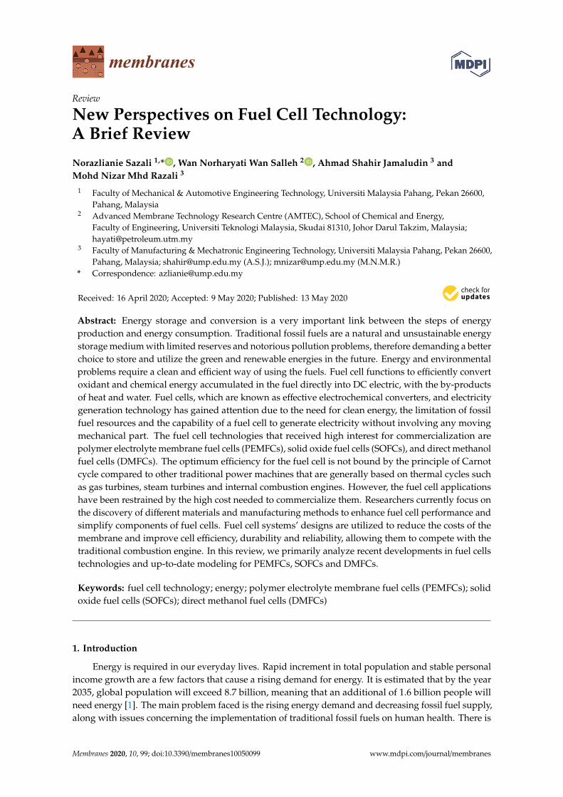
In PEMFCs, the generation of heat appeared due to the entropic heat reaction and the presence ofirredeemable that is connected to the hydrogen. Aside from that, the stimulation of the electrochemicalreaction and ohmic resistances in contradiction of pathway of proton and electron flow as well as theheat transport of hydrogen to anode also affect the heat present in PEMFCs systems as in Figure 5 [16,64].The total heat produced in the system can be measured by equating the voltage of single cell withoutput voltage of 100% effectual PEMFCs. Generally, the produced heat in the PEMFCs is about 60%
Membranes 2020, 10, 99 8 of 18
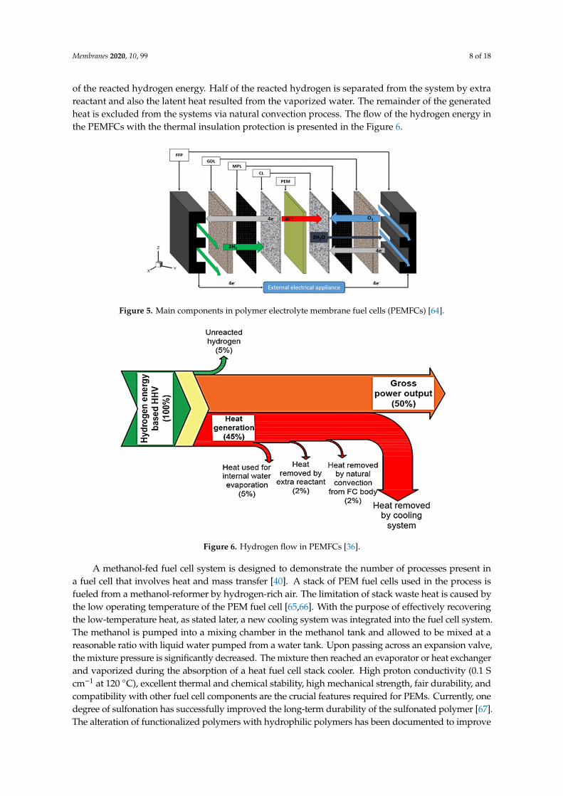
of the reacted hydrogen energy. Half of the reacted hydrogen is separated from the system by extrareactant and also the latent heat resulted from the vaporized water. The remainder of the generatedheat is excluded from the systems via natural convection process. The flow of the hydrogen energy inthe PEMFCs with the thermal insulation protection is presented in the Figure 6.
Membranes 2020, 10, x FOR PEER REVIEW 8 of 18
In PEMFCs, the generation of heat appeared due to the entropic heat reaction and the presence of irredeemable that is connected to the hydrogen. Aside from that, the stimulation of the electrochemical reaction and ohmic resistances in contradiction of pathway of proton and electron flow as well as the heat transport of hydrogen to anode also affect the heat present in PEMFCs systems as in Figure 5 [16,64]. The total heat produced in the system can be measured by equating the voltage of single cell with output voltage of 100% effectual PEMFCs. Generally, the produced heat in the PEMFCs is about 60% of the reacted hydrogen energy. Half of the reacted hydrogen is separated from the system by extra reactant and also the latent heat resulted from the vaporized water. The remainder of the generated heat is excluded from the systems via natural convection process. The flow of the hydrogen energy in the PEMFCs with the thermal insulation protection is presented in the Figure 6.
Figure 5. Main components in polymer electrolyte membrane fuel cells (PEMFCs) [64].
Figure 6. Hydrogen flow in PEMFCs [36].
A methanol-fed fuel cell system is designed to demonstrate the number of processes present in a fuel cell that involves heat and mass transfer [40]. A stack of PEM fuel cells used in the process is fueled from a methanol-reformer by hydrogen-rich air. The limitation of stack waste heat is caused by the low operating temperature of the PEM fuel cell [65,66]. With the purpose of effectively recovering the low-temperature heat, as stated later, a new cooling system was integrated into the fuel cell system. The methanol is pumped into a mixing chamber in the methanol tank and allowed to be mixed at a reasonable ratio with liquid water pumped from a water tank. Upon passing across
Figure 5. Main components in polymer electrolyte membrane fuel cells (PEMFCs) [64].
Membranes 2020, 10, x FOR PEER REVIEW 8 of 18
In PEMFCs, the generation of heat appeared due to the entropic heat reaction and the presence of irredeemable that is connected to the hydrogen. Aside from that, the stimulation of the electrochemical reaction and ohmic resistances in contradiction of pathway of proton and electron flow as well as the heat transport of hydrogen to anode also affect the heat present in PEMFCs systems as in Figure 5 [16,64]. The total heat produced in the system can be measured by equating the voltage of single cell with output voltage of 100% effectual PEMFCs. Generally, the produced heat in the PEMFCs is about 60% of the reacted hydrogen energy. Half of the reacted hydrogen is separated from the system by extra reactant and also the latent heat resulted from the vaporized water. The remainder of the generated heat is excluded from the systems via natural convection process. The flow of the hydrogen energy in the PEMFCs with the thermal insulation protection is presented in the Figure 6.
Figure 5. Main components in polymer electrolyte membrane fuel cells (PEMFCs) [64].
Figure 6. Hydrogen flow in PEMFCs [36].
A methanol-fed fuel cell system is designed to demonstrate the number of processes present in a fuel cell that involves heat and mass transfer [40]. A stack of PEM fuel cells used in the process is fueled from a methanol-reformer by hydrogen-rich air. The limitation of stack waste heat is caused by the low operating temperature of the PEM fuel cell [65,66]. With the purpose of effectively recovering the low-temperature heat, as stated later, a new cooling system was integrated into the fuel cell system. The methanol is pumped into a mixing chamber in the methanol tank and allowed to be mixed at a reasonable ratio with liquid water pumped from a water tank. Upon passing across
Figure 6. Hydrogen flow in PEMFCs [36].
A methanol-fed fuel cell system is designed to demonstrate the number of processes present ina fuel cell that involves heat and mass transfer [40]. A stack of PEM fuel cells used in the process isfueled from a methanol-reformer by hydrogen-rich air. The limitation of stack waste heat is caused bythe low operating temperature of the PEM fuel cell [65,66]. With the purpose of effectively recoveringthe low-temperature heat, as stated later, a new cooling system was integrated into the fuel cell system.The methanol is pumped into a mixing chamber in the methanol tank and allowed to be mixed at areasonable ratio with liquid water pumped from a water tank. Upon passing across an expansion valve,the mixture pressure is significantly decreased. The mixture then reached an evaporator or heat exchangerand vaporized during the absorption of a heat fuel cell stack cooler. High proton conductivity (0.1 Scm−1 at 120 ◦C), excellent thermal and chemical stability, high mechanical strength, fair durability, andcompatibility with other fuel cell components are the crucial features required for PEMs. Currently, onedegree of sulfonation has successfully improved the long-term durability of the sulfonated polymer [67].The alteration of functionalized polymers with hydrophilic polymers has been documented to improve
Membranes 2020, 10, 99 9 of 18
the thermal characteristics and organic phase interaction for thermal-specific applications [68]. Withal,polymer alteration with inorganic materials, for instance, silica, metal oxides, clays, carbon nanotubes,and others shows higher improvisation toward the fuel cell characteristics of PEM [69].
The fundamentals theory and the practical operation of a PEMFC involve various mathematicalmodels presented in this section. Peng and groups had constructed the equivalent modeling ofmembrane hydration dynamic inside PEMFC in order to minimize the membrane micro-flooding.From the results, it was found that the implementation of the studied model able to improve themaximum net power boost can be estimated as being up to 3.74%, which is essential for the optimaloperation of the integrated PEMFC system to achieve a higher system efficiency [70]. In anotherstudy by Salimi et al., the neural network modeling is found able to increase the power output of thePEMFC systems [71].Through the designated model named an artificial neural network (ANN), theoperating performance increased up to 28.9%. A comprehensive stack model is developed based onthe integration of a 1 + 1 dimensional multiphase stack sub-model and a flow distribution sub-modelhas been developed [72]. The purpose of the constructed model is to study the flow distributionsas well as reactions, phase changes, and transport processes inside the PEMFC. From the obtaineddata analysis, the uniform flow assumption not only overestimates the stack output performancebut also underestimates the fuel cell voltage variations. Besides, neglecting the non-uniform flowdistribution may lead to higher predictions of the overall stack temperature and lower predictions ofthe temperature variations among different fuel cells. In other approaches by Chugh and colleagues,the low temperature of PEMFC performance is deeply studied via the mathematical modeling, whichis MATLAB. The model predicts an increase in PEMFC performance with an increase in operatingtemperature, pressure and reactant humidity. An increase in stack operating temperature from 50to 80 ◦C was seen to increase the stack voltage by 25%, because of lowering the activation potentialand ohmic resistance. However, a further increase in operating temperature results in membranedehydration. Similarly, a 30% increase in stack output power was observed upon increasing theoperating pressure from 0 to 100 kPag. The further increase in pressure to 200 kPag showed a 60%increase in the output power [73]. In PEMFC, the water transport behavior in the gas diffusion layer(GDL) and bipolar plate (BPP) affected by the nonuniform compression on the GDL. Thus, Xu et al.studied these effects via the constructed model to obtain the relationship between the GDL deformationand assembly clamping force based on the energy method [74]. From the proposed model, the resultsshow that drainage pressure increases monotonically with the assembly clamping force. In addition,thin GDL is conducive to improving drainage capacity. However, due to the combined effect ofthrough-plane and in-plane mass transport in GDL, the maximum pressure first decreases and thenincreases with the thickness of GDL. GDL with a thickness of 0.2 mm is regarded as the best size toguarantee good water transport for the baseline case.
The introduction of combination between inorganic materials and PEMs, resulting in thedevelopment of nanocomposite membranes, in which the nanostructures lead to the improvement ofmechanical and thermal stability of the membranes [75]. Proton conduction is the dominant aspect inthe membrane’s analysis for fuel cell potential applications in which high conductivity is important.The two main mechanisms can elucidate the protons’ transfer in a hydrated polymer membrane, whichis vehicular and Grotthus [76,77]. The Grotthus mechanism performs through the migration of protonsacross polymer matrices from one hydrolyzed ion to another [78]. The protons generated at the anodeby hydrogen oxidation are added to water molecules to produce hydronium ions. The result of theGrotthus mechanism is the conductivity of a perfluorinated sulfonic acid membrane, for instance,Nafion®. The value of the ion exchange capacity (IEC) affects the transfer of Grotthus type due to therecommended loading quantity of ionizable groups in the membrane of fuel cells [79]. Hydroniumions pass through either the aqueous medium with one or more methanol or water molecules viaelectro-osmotic drag in the membrane for the vehicle mechanism. Consequently, the molecules ofmethanol or water function as vehicles for the diffusion of protons in the polymeric membrane. Cationiccomplexes are created after joining protons with molecules of water or methanol. An integral feature

Membranes 2020, 10, 99 10 of 18
in the vehicular mechanism is the free volume existence in polymeric chains of proton exchangemembranes [80]. This method can be employed to choose inorganic additives to enhance polymericmembrane proton conductivity at low RH conditions and high temperatures [81].
2.4. Solid Oxide Fuel Cell (SOFCs)
The capability of the SOFCs to act as the sustainable energy supply has been explored andscientifically reported since 1990s. The pros and cons of the SOFCs is tabulated in Table 1 [82,83].SOFCs are high-temperature fuel cells that have recently attracted the most attention for applicationsin cooling, heating and power generation systems. There are two types of electrolytes in SOFCs, whichare oxygen ion-conducting (SOFC–O2−) and proton-conducting (SOFC–H+). Both the modeling forSOFC–O2− and SOFC–H+ is illustrated in Figure 7. As can be seen in Figure 7, in SOFC–O2, the oxygenmolecules freely pass through the electrolyte and react with hydrogen gas at anode side. By reacting theion of oxygen with the proton, the steam forms at anode side. Meanwhile, the steam is produced andexits the cathode side as the hydrogen molecules from the anode reacts SOFC–H+ electrolyte. Li et al.cited that SOFC–H+ offers a low working temperature to prolong the lifetime of the cell [84]. The authorsmentioned that the poor chemical stability of BaCeO3-based SOFC–H+ limits the practical applications.Thus, BaZrO3-based proton-conducting oxides are intensively studied because they are chemicallystable while offering high bulk conductivity. Xu et al. mentioned that the first-generation SOFCcathodes, including La1-xSrxMO3 (M = Mn and Fe), show good chemical stability as well as excellentchemical and thermal compatibility with electrolyte materials. However, these cathodes are not fullypractical in certain applications due to their low performance. Thus, La0.5Sr0.5FeO3-δ with Pr-dopingwere successfully fabricated in order to minimize the existing limitations [85]. The complex oxide ofBaCe0.7−xZr0.2Y0.1Fex03−δ was successfully designed by Tarutina et al. for SOFC–H+ [86]. Based onthe findings, the Fe-doping has a positive effect on the densification of the materials which leading toimprove grain growth at reduced sintering temperature. Working from a different perspective, forMojaver and colleagues, the energy efficiency of an SOFC–O2-based system, is higher, which is 60.20%compared to SOFC–H+ with 54.06%. The sum of the unit cost of the product (SUPC) of SOFC–O2− islower (48.24 $/GJ compared to 48.75 $/GJ) rather than SOFC–H+. In addition, the power produced bySOFC–O2− is 18 kW greater than SOFC–H+. Directly, this led to improving the system power from147.9 kW for SOFC–H+ and 156.4 kW in the case of the SOFC–O2− [87].
Membranes 2020, 10, x FOR PEER REVIEW 10 of 18
Grotthus type due to the recommended loading quantity of ionizable groups in the membrane of fuel cells [79]. Hydronium ions pass through either the aqueous medium with one or more methanol or water molecules via electro-osmotic drag in the membrane for the vehicle mechanism. Consequently, the molecules of methanol or water function as vehicles for the diffusion of protons in the polymeric membrane. Cationic complexes are created after joining protons with molecules of water or methanol. An integral feature in the vehicular mechanism is the free volume existence in polymeric chains of proton exchange membranes [80]. This method can be employed to choose inorganic additives to enhance polymeric membrane proton conductivity at low RH conditions and high temperatures [81].
2.4. Solid Oxide Fuel Cell (SOFCs)
The capability of the SOFCs to act as the sustainable energy supply has been explored and scientifically reported since 1990s. The pros and cons of the SOFCs is tabulated in Table 1 [82,83]. SOFCs are high-temperature fuel cells that have recently attracted the most attention for applications in cooling, heating and power generation systems. There are two types of electrolytes in SOFCs, which are oxygen ion-conducting (SOFC–O2-) and proton-conducting (SOFC–H+). Both the modeling for SOFC–O2− and SOFC–H+ is illustrated in Figure 7. As can be seen in Figure 7, in SOFC–O2, the oxygen molecules freely pass through the electrolyte and react with hydrogen gas at anode side. By reacting the ion of oxygen with the proton, the steam forms at anode side. Meanwhile, the steam is produced and exits the cathode side as the hydrogen molecules from the anode reacts SOFC–H+ electrolyte. Li et al. cited that SOFC–H+ offers a low working temperature to prolong the lifetime of the cell [84]. The authors mentioned that the poor chemical stability of BaCeO3-based SOFC–H+ limits the practical applications. Thus, BaZrO3-based proton-conducting oxides are intensively studied because they are chemically stable while offering high bulk conductivity. Xu et al. mentioned that the first-generation SOFC cathodes, including La1-xSrxMO3 (M = Mn and Fe), show good chemical stability as well as excellent chemical and thermal compatibility with electrolyte materials. However, these cathodes are not fully practical in certain applications due to their low performance. Thus, La0.5Sr0.5FeO3-δ with Pr-doping were successfully fabricated in order to minimize the existing limitations [85]. The complex oxide of BaCe0.7−xZr0.2Y0.1Fex03−δ was successfully designed by Tarutina et al. for SOFC–H+ [86]. Based on the findings, the Fe-doping has a positive effect on the densification of the materials which leading to improve grain growth at reduced sintering temperature. Working from a different perspective, for Mojaver and colleagues, the energy efficiency of an SOFC–O2-based system, is higher, which is 60.20% compared to SOFC–H+ with 54.06%. The sum of the unit cost of the product (SUPC) of SOFC–O2− is lower (48.24 $/GJ compared to 48.75 $/GJ) rather than SOFC–H+. In addition, the power produced by SOFC–O2− is 18 kW greater than SOFC–H+. Directly, this led to improving the system power from 147.9 kW for SOFC–H+ and 156.4 kW in the case of the SOFC–O2− [87].
Figure 7. Modeling of (A) Oxygen ion-conducting SOFC–O2− and (B) Proton-conducting SOFC–H+
[88]. Figure 7. Modeling of (A) Oxygen ion-conducting SOFC–O2− and (B) Proton-conducting SOFC–H+ [88].
This subtopic discusses the SOFC’s models and operations, considering the thermal managementrequirements and material-based restrictions. The fundamental theory and the practical operationof an SOFC involve various mathematical models presented by researchers. The basic interest ofmodels is the ideal efficiency of combined cycle plants from SOFC. Chan et al. studied to constructa thermodynamic model for simple hydrogen and methane fed SOFC power systems in which heatrecovered was used to pre-heat air and fuel [89]. Winkler and Lorenz hypothesized that the simplycombined efficiency of the SOFC and the gas turbine cycle ranges from 60% to 70% [90]. Besides, they

Membranes 2020, 10, 99 11 of 18
proposed a cycle of RH–SOFC–GT–ST which stands for ReHeat–SOFC–Gas Turbine–Steam Turbinethat was proven to have more than 80 percent efficiency and supports the theoretical thermodynamicmodel’s predictions. Jurado developed a dynamic model to compute low-order linear system modelsof SOFCs from the time domain to study the potential effects of fuel cells on future distributionsystems [91,92].
Table 1. Benefits and the limitations of solid oxide fuel cells (SOFCs) [82,83].
Benefits
The consistency of the size and air flow in SOFC stack size is maintained.Pressure value is maintained along with the pressured existing SOFC stacks.Turbine inlet temperature values close to stack discharge conditions.Available air temperature values near to SOFC cathode inlet.Promising electrical integration at continuous current level.
Limitations
Commercial microturbines not specially premeditated for SOFC.Substantial impact of ambient temperature value.Plant exhaust flow temperature unable to decrease less than 200 to 250 ◦C.The controllability of dynamic issues.
This model applied the Box–Jenkins algorithm for calculating a linear system’s transfer functionfrom input and output samples, which is able to modulate reactive and real power regarding of changesin frequency and voltage on the grid. The analysis of energy balance was carried out by Van Herleet al. on a biogas-fed SOFC combined with heat and a small gas engine system [93]. A numericalmodel for SOFC was developed by Petruzzi et al. [94]. This is built for the convenience of luxurycars as an auxiliary power unit (APU). The model functions to simulate the thermal-electrochemicalbehaviour during operation in all possible conditions. A simulation model of an SOFC power plant wasdeveloped by Padullés et al. to be used in common commercial power system simulation package [95].Many researchers have studied chemical equilibrium issues for an SOFC using internal reformingalso shifting reactions in situations where there is the usage of natural gas, methane or biogas as fuel.Pre-reformer fuel gas consists of H2, CO2, CO, CH4 and H2O (vapour). In the cell, a combination ofshifting and reforming reactions occurs. A fuel plug-flow model (natural gas surrogate) at the anodechannels was studied by Walters et al. [96]. The model developed takes into account the basic gas-phasechemical kinetics of oxidation and pyrolysis of oil, also the limiting case of local chemical balance.
Guo et al. carried out a study on the efficiency of methane oxidative coupling affected by thedifferent operating parameters [97]. Two mathematical models focusing on plug flow and well-mixedflow was implemented to explain SOFCs behavior. Intensive studies have been done related to thepotential electrical losses in an SOFC’s operation, involving ohmic loss, activation polarization andlosses because of mass transportation resistance. SOFC systems operate between 900 and 1000 ◦C,higher than any other type of fuel cell system [98]. Virkar et al. analyzed the overall SOFC stackresistance dependency quantitatively as a function of transport characteristics, cathode thickness,interconnecting contact area, anode thickness, electrolyte thickness and interconnecting contact spacingassociated with interfaces and each region (resistance of charge transfer) [99]. A ladder networkapproach was used to study the closed-form analytical expressions. From a mathematical model andexperimental research, Fukunaga et al. studied the relation between the three-phase boundary (TPB)distance and the over-potential [100]. They found that values less than 20 lm is the effective thicknessof (TPB) length. Based on an analytical model, the optimization of cermet SOFC electrodes and limitingbehavior have been explained. The absence of a liquid phase causes the modeling of heat transfer in anSOFC to become more tractable.
Iwata et al. presented their SOFC model, which discussed the relationship between the profile ofhigh temperature and the current density [101]. The studies revealed that temperature depends onpower density. Numerical methods were used to analyze the coupled flow processes, mass/heat transfer,electrochemistry and chemical reaction. A tubular SOFC thermal transport model was developed byHaynes and Wepfer, and they stated that the primary heat transfer mechanism between the cell and

Membranes 2020, 10, 99 12 of 18
the air supply tube was radiation [102]. Larrain et al. implemented a parameter estimation approachto investigate parameters for a simple kinetic and thermal model used for small SOFC (20 cm2 ofanode-supported electrolyte with an active area of 1 cm2) [103]. Khaleel et al. incorporated MARC,a commercial finite element analysis code, with an electrochemical (EC) module formed in-house tosimulate SOFCs of the planar type [104]. This EC module measures the distribution of heat generation,current density as well as oxidant and fuel concentration, including MARC’s temperature profile.MARC conducts thermal and flow evaluation according to the boundary and initial of flow and thermalconditions, as well as the heat generation measured by the EC module. The operating conditionsof a rectangular planar SOFC with an integrated air preheater were examined by Costamagna andco-workers [105].
The fuel cell system is built with the purpose of reducing the high-cost preheater for external airusing lower airflow rates along with lower inlet temperature. An analytical form for the gas-flowdistribution in a planar SOFC stack, assuming that the stack is seen as a hydraulic resistance network,has been reported by Boersma and Sammes [106,107]. Research has directed towards minimizing itsthickness and searching new ion conductors to lower the electrolyte’s resistivity. Dotelli et al. employeda digital simulation technique based on images to simulate the composite electrolyte’s electricalbehavior [108]. Voronoi tessellation is used to convert the two-phase polyhedral microstructures into arandom electrical network [109]. The actual and imaginary part of the electrical network impedancewas calculated by the method of the transfer matrix. Scott et al. formed a mathematical modelexplaining the distribution along with the electrolyte thickness of the electron holes and electronsconcentration as well as the potential [110].
Interest in research on modeling SOFCs has also been growing over the past couple of years [111–113].Modeling works in a fuel cell usually focused on an area or factor. There are also other conditionstabulated in the table. Spatial dimensions, for example, could be in the range of simple zero dimensionsto complex three dimensions. The model’s state is known to be a steady or transient state. At elevatedoperating temperatures, only gas remains in SOFCs. In order to study the integration of fuel cellswith other energy storage components and power, modeling is required to be performed at themacrosystem level.
3. Conclusions
The fuel cell system design can be seen as a decision-making process that comprises of identifyingpotential design alternatives and selecting the most appropriate one. It can be classified as gooddesign if it meets the design specifications as well as a trade-off between the various design goals.The specifications and goals for a fuel cell system consist of performance, dimension, which is weightand size, emissions, output power, rapid start-up and rapid response to changes in load, lifetime,and operability in intense environments and noise, which will be important in certain applications.Considerable attention is being paid to the utilization of computer-based and modeling optimizationin fuel cell systems design. One advantage of this method is the positive effect on high cost anddesign cycle time savings, as well as its improved operation and design. The performance of optimumdevelopment depends primarily on the method by which the prototype is developed. It is crucialto identify the important factors and those that can be compromised without having an adverseeffect on the design. Modeling is carried out to capture the designer’s interest aspects of the fuel cellsystem. A mathematical model that represents particular fuel cell system aspects and estimates itscharacteristics can be in a form of algebraic equations, differential equations, or a process or subroutinebased on a computer. The model can involve various alternatives to the design that can be achieved bychanging parameters, variables, constraints or conditions. The principle explained in the precedingstep contributes to the basis for comparing the various alternatives to design. Then, the prototypecan be combined with a numerical optimization algorithm to produce improved designs iteratively.This can lead to one or more optimal solutions. Modeling and optimization will assist the designer infurther consideration of shortlisting the designs. However, optimization will not always produce a

Membranes 2020, 10, 99 13 of 18
better design appropriate for manufacturing. In this situation, the iteration of the preceding points isrequired to confirm that suitable fuel cell phenomena are captured in the model and exact governingequations are employed, the assumptions’ validity employed in modeling is analyzed, as well as toconfirm that the design specifications and goals are modified and altered if necessary. The final designwill result in either a final prototype or an improvement of an existing design to be developed inthe future.
Funding: This research was funded by Internal Research Grant Scheme [grant number; RDU1803133].
Acknowledgments: The authors would like to thank the Ministry of Higher Education and UniversityMalaysia Pahang for the financial support provided under the Internal Research Grant Scheme (Project Number:RDU1803133) in completing this work.
Conflicts of Interest: The authors declare no conflict of interest.
References
1. Senjyu, T.; Howlader, A.M. Operational aspects of distribution systems with massive DER penetrations.Integr. Distrib. Energy Resour. Power Syst. 2016, 51–76. [CrossRef]
2. Bilgili, M.; Özbek, A.; Sahin, B.; Kahraman, A. An overview of renewable electric power capacity andprogress in new technologies in the world. Renew. Sustain. Energy Rev. 2015, 49, 323–334. [CrossRef]
3. Ajanovic, A.; Haas, R. Economic prospects and policy framework for hydrogen as fuel in the transport sector.Energy Policy 2018, 123, 280–288. [CrossRef]
4. Hames, Y.; Kaya, K.; Baltacioglu, E.; Turksoy, A. Analysis of the control strategies for fuel saving in thehydrogen fuel cell vehicles. Int. J. Hydrog. Energy 2018, 43, 10810–10821. [CrossRef]
5. Salleh, M.T.; Jaafar, J.; Mohamed, M.A.; Norddin, M.; Ismail, A.F.; Othman, M.; Rahman, M.A.; Yusof, N.;Aziz, F.; Salleh, W.N.W. Stability of SPEEK/Cloisite®/TAP nanocomposite membrane under Fenton reagentcondition for direct methanol fuel cell application. Polym. Degrad. Stab. 2017, 137, 83–99. [CrossRef]
6. Kim, D.J.; Jo, M.J.; Nam, S.Y. A review of polymer–nanocomposite electrolyte membranes for fuel cellapplication. J. Ind. Eng. Chem. 2015, 21, 36–52. [CrossRef]
7. Karimi, M.B.; Mohammadi, F.; Hooshyari, K. Recent approaches to improve Nafion performance for fuel cellapplications: A review. Int. J. Hydrog. Energy 2019, 44, 28919–28938. [CrossRef]
8. Li, H.; Zhang, G.; Wu, J.; Zhao, C.; Jia, Q.; Lew, C.M.; Zhang, L.; Zhang, Y.; Han, M.; Zhu, J.; et al. A facileapproach to prepare self-cross-linkable sulfonated poly(ether ether ketone) membranes for direct methanolfuel cells. J. Power Sources 2010, 195, 8061–8066. [CrossRef]
9. Kim, K.; Heo, P.; Han, J.; Kim, J.; Lee, J.-C. End-group cross-linked sulfonated poly(arylene ether sulfone) viathiol-ene click reaction for high-performance proton exchange membrane. J. Power Sources 2018, 401, 20–28.[CrossRef]
10. Pan, L.; Ott, S.; Dionigi, F.; Strasser, P. Current challenges related to the deployment of shape-controlledPt alloy oxygen reduction reaction nanocatalysts into low Pt-loaded cathode layers of proton exchangemembrane fuel cells. Curr. Opin. Electrochem. 2019, 18, 61–71. [CrossRef]
11. Liu, X.; Reddi, K.; Elgowainy, A.; Lohse-Busch, H.; Wang, M.; Rustagi, N. Comparison of well-to-wheelsenergy use and emissions of a hydrogen fuel cell electric vehicle relative to a conventional gasoline-poweredinternal combustion engine vehicle. Int. J. Hydrog. Energy 2020, 45, 972–983. [CrossRef]
12. Sun, T.; Zhang, X.; Chen, B.; Liu, X. Coordination control strategy for the air management of heavy vehiclefuel cell engine. Int. J. Hydrog. Energy 2019. [CrossRef]
13. Hossain, S.; Abdalla, A.M.; Suhaili, S.B.H.; Kamal, I.; Shaikh, S.P.S.; Dawood, M.K.; Azad, A.K. Nanostructuredgraphene materials utilization in fuel cells and batteries: A review. J. Energy Storage 2020, 29, 101386.[CrossRef]
14. Haghi, E.; Shamsi, H.; Dimitrov, S.; Fowler, M.; Raahemifar, K. Assessing the potential of fuel cell-poweredand battery-powered forklifts for reducing GHG emissions using clean surplus power; a game theoryapproach. Int. J. Hydrog. Energy 2020. [CrossRef]
15. Cano, Z.P.; Banham, D.; Ye, S.; Hintennach, A.; Lu, J.; Fowler, M.; Chen, Z. Batteries and fuel cells foremerging electric vehicle markets. Nat. Energy 2018, 3, 279–289. [CrossRef]

Membranes 2020, 10, 99 14 of 18
16. Inci, M.; Turksoy, O. Review of fuel cells to grid interface: Configurations, technical challenges and trends. J.Clean. Prod. 2019, 213, 1353–1370. [CrossRef]
17. Widera, B. Renewable hydrogen implementations for combined energy storage, transportation and stationaryapplications. Therm. Sci. Eng. Prog. 2020, 16, 100460. [CrossRef]
18. Wang, Y.; Diaz, D.F.R.; Chen, K.S.; Wang, Z.; Adroher, X.C. Materials, technological status, and fundamentalsof PEM fuel cells—A review. Mater. Today 2020, 32, 178–203. [CrossRef]
19. Siwal, S.S.; Thakur, S.; Zhang, Q.; Thakur, V. Electrocatalysts for electrooxidation of direct alcohol fuel cell:Chemistry and applications. Mater. Today Chem. 2019, 14, 100182. [CrossRef]
20. Mallick, R.; Thombre, S.B.; Shrivastava, N.K. Vapor feed direct methanol fuel cells (DMFCs): A review.Renew. Sustain. Energy Rev. 2016, 56, 51–74. [CrossRef]
21. Jaafar, J.; Ismail, A.F.; Matsuura, T.; Nagai, K. Performance of SPEEK based polymer–nanoclay inorganicmembrane for DMFC. J. Membr. Sci. 2011, 382, 202–211. [CrossRef]
22. Kamarudin, S.K.; Achmad, F.; Daud, W.R.W. Overview on the application of direct methanol fuel cell (DMFC)for portable electronic devices. Int. J. Hydrog. Energy 2009, 34, 6902–6916. [CrossRef]
23. Kamarudin, S.K.; Daud, W.R.W.; Ho, S.L.; Hasran, U. Overview on the challenges and developments ofmicro-direct methanol fuel cells (DMFC). J. Power Sources 2007, 163, 743–754. [CrossRef]
24. Asensio, F.J.; Martin, J.I.S.; Zamora, I.; Saldaña, G.; Oñederra, O. Analysis of electrochemical and thermalmodels and modeling techniques for polymer electrolyte membrane fuel cells. Renew. Sustain. Energy Rev.2019, 113, 109283. [CrossRef]
25. Moreno, N.G.; Molina, M.C.; Gervasio, D.; Robles, J.F.P. Approaches to polymer electrolyte membrane fuelcells (PEMFCs) and their cost. Renew. Sustain. Energy Rev. 2015, 52, 897–906. [CrossRef]
26. Chandan, A.; Hattenberger, M.; El-Kharouf, A.; Du, S.; Dhir, A.; Self, V.; Pollet, B.G.; Ingram, A.; Bujalski, W.High temperature (HT) polymer electrolyte membrane fuel cells (PEMFC)—A review. J. Power Sources 2013,231, 264–278. [CrossRef]
27. Alcaide, F.; Cabot, P.-L.; Brillas, E. Fuel cells for chemicals and energy cogeneration. J. Power Sources 2006,153, 47–60. [CrossRef]
28. Arshad, A.; Ali, H.M.; Habib, A.; Bashir, M.A.; Jabbal, M.; Yan, Y. Energy and exergy analysis of fuel cells: Areview. Therm. Sci. Eng. Prog. 2019, 9, 308–321. [CrossRef]
29. Wee, J.-H. Carbon dioxide emission reduction using molten carbonate fuel cell systems. Renew. Sustain.Energy Rev. 2014, 32, 178–191. [CrossRef]
30. Rahman, S.; Masdar, M.S.; Rosli, M.; Majlan, E.; Husaini, T.; Kamarudin, S.; Daud, W. Overview biohydrogentechnologies and application in fuel cell technology. Renew. Sustain. Energy Rev. 2016, 66, 137–162. [CrossRef]
31. Jeon, D.H. Computational fluid dynamics simulation of anode-supported solid oxide fuel cells withimplementing complete overpotential model. Energy 2019, 188, 116050. [CrossRef]
32. Wang, H.-N.; Zhu, X.; Zhang, B.; Ye, D.; Chen, R.; Liao, Q.; Sui, P.-C.; Djilali, N. Two-phase computationalmodelling of a membraneless microfluidic fuel cell with a flow-through porous anode. J. Power Sources 2019,420, 88–98. [CrossRef]
33. Ly, H.; Birgersson, E.; Vynnycky, M. Computationally efficient multi-phase models for a proton exchangemembrane fuel cell: Asymptotic reduction and thermal decoupling. Int. J. Hydrog. Energy 2011, 36,14573–14589. [CrossRef]
34. Vorobev, A.; Zikanov, O.; Shamim, T. A computational model of a PEM fuel cell with finite vapor absorptionrate. J. Power Sources 2007, 166, 92–103. [CrossRef]
35. Sharma, A.K.; Birgersson, E.; Khor, S. Computationally-efficient hybrid strategy for mechanistic modeling offuel cell stacks. J. Power Sources 2014, 247, 481–488. [CrossRef]
36. Nguyen, H.Q.; Shabani, B. Proton exchange membrane fuel cells heat recovery opportunities for combinedheating/cooling and power applications. Energy Convers. Manag. 2020, 204, 112328. [CrossRef]
37. Amoatey, P.; Omidvarborna, H.; Baawain, M.S.; Al-Mamun, A. Emissions and exposure assessments of SOX,NOX, PM10/2.5 and trace metals from oil industries: A review study (2000–2018). Process. Saf. Environ. Prot.2019, 123, 215–228. [CrossRef]
38. Kamarudin, S.; Hashim, N. Materials, morphologies and structures of MEAs in DMFCs. Renew. Sustain.Energy Rev. 2012, 16, 2494–2515. [CrossRef]
39. Sharma, S.; Pollet, B.G. Support materials for PEMFC and DMFC electrocatalysts—A review. J. Power Sources2012, 208, 96–119. [CrossRef]

Membranes 2020, 10, 99 15 of 18
40. Akbari, E.; Buntat, Z.; Nikoukar, A.; Kheirandish, A.; Khaledian, M.; Afroozeh, A.; Khaledian, M. Sensorapplication in Direct Methanol Fuel Cells (DMFCs). Renew. Sustain. Energy Rev. 2016, 60, 1125–1139.[CrossRef]
41. Deng, R.; Xia, Z.; Sun, R.; Wang, S.; Sun, G. Nanostructured ultrathin catalyst layer with ordered platinumnanotube arrays for polymer electrolyte membrane fuel cells. J. Energy Chem. 2020, 43, 33–39. [CrossRef]
42. Zhao, J.; Shahgaldi, S.; Ozden, A.; Alaefour, I.E.; Li, X.; Hamdullahpur, F. Effect of catalyst deposition onelectrode structure, mass transport and performance of polymer electrolyte membrane fuel cells. Appl.Energy 2019, 255, 113802. [CrossRef]
43. Star, A.G.; Wang, G.; Medina, S.; Pylypenko, S.; Neyerlin, K. Mass transport characterization of platinum groupmetal-free polymer electrolyte fuel cell electrodes using a differential cell with an integrated electrochemicalsensor. J. Power Sources 2020, 450, 227655. [CrossRef]
44. Lee, C.; Lee, J.; Zhao, B.; Fahy, K.; Lamanna, J.; Baltic, E.; Hussey, D.; Jacobson, D.; Schulz, V.; Bazylak, A.Temperature-dependent gas accumulation in polymer electrolyte membrane electrolyzer porous transportlayers. J. Power Sources 2020, 446, 227312. [CrossRef]
45. Tiwari, J.N.; Tiwari, R.N.; Singh, G.; Kim, K.S. Recent progress in the development of anode and cathodecatalysts for direct methanol fuel cells. Nano Energy 2013, 2, 553–578. [CrossRef]
46. Wang, J. System integration, durability and reliability of fuel cells: Challenges and solutions. Appl. Energy2017, 189, 460–479. [CrossRef]
47. Brouzgou, A.; Song, S.; Tsiakarasbcd, P. Low and non-platinum electrocatalysts for PEMFCs: Current status,challenges and prospects. Appl. Catal. B Environ. 2012, 127, 371–388. [CrossRef]
48. Kulikovsky, A. Direct methanol–hydrogen fuel cell: The mechanism of functioning. Electrochem. Commun.2008, 10, 1415–1418. [CrossRef]
49. Pramanik, H.; Basu, S. Modeling and experimental validation of overpotentials of a direct ethanol fuel cell.Chem. Eng. Process. Process. Intensif. 2010, 49, 635–642. [CrossRef]
50. Jeng, K.; Chen, C. Modeling and simulation of a direct methanol fuel cell anode. J. Power Sources 2002, 112,367–375. [CrossRef]
51. Kulikovsky, A. Analytical model of the anode side of DMFC: The effect of non-Tafel kinetics on cellperformance. Electrochem. Commun. 2003, 5, 530–538. [CrossRef]
52. Rosenthal, N.S.; Vilekar, S.A.; Datta, R. A comprehensive yet comprehensible analytical model for the directmethanol fuel cell. J. Power Sources 2012, 206, 129–143. [CrossRef]
53. Kulikovsky, A. Comment on “A one dimensional model of a methanol fuel cell anode” [K. Scott, P.Argyropoulos, J. Power Sources 137 (2004) 228]. J. Power Sources 2005, 148, 54. [CrossRef]
54. Chen, R.; Zhao, T. Mathematical modeling of a passive-feed DMFC with heat transfer effect. J. Power Sources2005, 152, 122–130. [CrossRef]
55. Theodosiou, P.; Greenman, J.; Ieropoulos, I. Towards monolithically printed Mfcs: Development of a3d-printable membrane electrode assembly (mea). Int. J. Hydrog. Energy 2019, 44, 4450–4462. [CrossRef]
56. Sun, W.; Zhang, W.; Su, H.; Leung, P.; Xing, L.; Xu, L.; Yang, C.; Xu, Q. Improving cell performance andalleviating performance degradation by constructing a novel structure of membrane electrode assembly(MEA) of DMFCs. Int. J. Hydrog. Energy 2019, 44, 32231–32239. [CrossRef]
57. Wang, Z.; Shao, Y.; Zuo, P.-J.; Wang, X.-P.; Yin, G.-P. Durability studies of unsupported Pt cathodic catalystwith working time of direct methanol fuel cells. J. Power Sources 2008, 185, 1066–1072. [CrossRef]
58. Jiang, R.; Rong, C.; Chu, D. Fuel Crossover and Energy Conversion in Lifetime Operation of Direct MethanolFuel Cells. J. Electrochem. Soc. 2007, 154, B13. [CrossRef]
59. Liu, J.; Zhou, Z.; Zhao, X.; Xin, Q.; Sun, G.; Yi, B. Studies on performance degradation of a direct methanolfuel cell (DMFC) in life test. Phys. Chem. Chem. Phys. 2004, 6, 134. [CrossRef]
60. Wang, Y.; Chen, K.S.; Mishler, J.; Cho, S.C.; Adroher, X.C. A review of polymer electrolyte membrane fuel cells:Technology, applications, and needs on fundamental research. Appl. Energy 2011, 88, 981–1007. [CrossRef]
61. Iulianelli, A.; Basile, A. Sulfonated PEEK-based polymers in PEMFC and DMFC applications: A review. Int.J. Hydrog. Energy 2012, 37, 15241–15255. [CrossRef]
62. Slater, J.; Chronopoulos, T.; Panesar, R.; Fitzgerald, F.; Garcia, M. Review and techno-economic assessment offuel cell technologies with CO2 capture. Int. J. Greenh. Gas Control 2019, 91, 102818. [CrossRef]
63. Valente, A.; Iribarren, D.; Dufour, J. End of life of fuel cells and hydrogen products: From technologies tostrategies. Int. J. Hydrog. Energy 2019, 44, 20965–20977. [CrossRef]

Membranes 2020, 10, 99 16 of 18
64. Xing, L.; Shi, W.; Su, H.; Xu, Q.; Das, P.; Mao, B.; Scott, K. Membrane electrode assemblies for PEM fuel cells:A review of functional graded design and optimization. Energy 2019, 177, 445–464. [CrossRef]
65. Abdel-Rehim, A.A. The influence of electromagnetic field on the performance and operation of a PEM fuelcell stack subjected to a relatively low electromagnetic field intensity. Energy Convers. Manag. 2019, 198,111906. [CrossRef]
66. Niroumand, A.M.; Homayouni, H.; Goransson, G.; Olfert, M.; Eikerling, M. In-situ diagnostic tools forhydrogen transfer leak characterization in PEM fuel cell stacks part III: Manufacturing applications. J. PowerSources 2020, 448, 227359. [CrossRef]
67. Haragirimana, A.; Ingabire, P.B.; Zhu, Y.; Lu, Y.; Li, N.; Hu, Z.; Chen, S. Four-polymer blend protonexchange membranes derived from sulfonated poly(aryl ether sulfone)s with various sulfonation degrees forapplication in fuel cells. J. Membr. Sci. 2019, 583, 209–219. [CrossRef]
68. Pasini, D.; Nitti, A. Free radical cyclopolymerization: A tool towards sequence control in functional polymers.Eur. Polym. J. 2020, 122, 109378. [CrossRef]
69. Simya, O.K.; Radhakrishnan, P.; Ashok, A. Engineered Nanomaterials for Energy Applications. In Handbookof Nanomaterials for Industrial Applications; Elsevier BV: Amsterdam, The Netherlands, 2018.
70. Peng, F.; Ren, L.; Zhao, Y.; Li, L. Hybrid dynamic modeling-based membrane hydration analysis for thecommercial high-power integrated PEMFC systems considering water transport equivalent. Energy Convers.Manag. 2020, 205, 112385. [CrossRef]
71. Nanadegani, F.S.; Lay, E.N.; Iranzo, A.; Salva, J.A.; Sundén, B. On neural network modeling to maximize thepower output of PEMFCs. Electrochim. Acta 2020, 348, 136345. [CrossRef]
72. Yang, Z.; Jiao, K.; Liu, Z.; Yin, Y.; Du, Q. Investigation of performance heterogeneity of PEMFC stack basedon 1+1D and flow distribution models. Energy Convers. Manag. 2020, 207, 112502. [CrossRef]
73. Chugh, S.; Chaudhari, C.; Sonkar, K.; Sharma, A.; Kapur, G.; Ramakumar, S. Experimental and modellingstudies of low temperature PEMFC performance. Int. J. Hydrog. Energy 2020, 45, 8866–8874. [CrossRef]
74. Xu, Y.; Qiu, D.; Yi, P.; Lan, S.; Peng, L. An integrated model of the water transport in nonuniform compressedgas diffusion layers for PEMFC. Int. J. Hydrog. Energy 2019, 44, 13777–13785. [CrossRef]
75. Wu, J.; Yuan, X.Z.; Martin, J.J.; Wang, H.; Zhang, J.; Shen, J.; Wu, S.; Mérida, W. A review of PEM fuelcell durability: Degradation mechanisms and mitigation strategies. J. Power Sources 2008, 184, 104–119.[CrossRef]
76. Zhang, J.; Liu, Y.; Lv, Z.; Zhao, T.; Li, P.; Sun, Y.; Wang, J. Sulfonated Ti3C2Tx to construct proton transferpathways in polymer electrolyte membrane for enhanced conduction. Solid State Ion. 2017, 310, 100–111.[CrossRef]
77. Yu, L.; Yue, B.; Yan, L.; Zhao, H.; Zhang, J. Proton conducting composite membranes based onsulfonated polysulfone and polysulfone-g-(phosphonated polystyrene) via controlled atom-transfer radicalpolymerization for fuel cell applications. Solid State Ion. 2019, 338, 103–112. [CrossRef]
78. Delemotte, L.; Van Keulen, S.; Roethlisberger, U.; Gianti, E.; Carnevale, V.; Klein, M.L. Does Proton Conductionin the Voltage-Gated Proton Channel hH V 1 Involve Grotthus Hopping via Acidic Residues? Biophys. J.2017, 112, 163a–164a. [CrossRef]
79. Vijayakumar, V.; Son, T.Y.; Kim, H.J.; Nam, S.Y. A facile approach to fabricate poly(2,6-dimethyl-1,4-phenyleneoxide) based anion exchange membranes with extended alkaline stability and ion conductivity for fuel cellapplications. J. Membr. Sci. 2019, 591, 117314. [CrossRef]
80. Yadav, V.; Rajput, A.; Sharma, P.P.; Jha, P.K.; Kulshrestha, V. Polyetherimide based anion exchange membranesfor alkaline fuel cell: Better ion transport properties and stability. Colloids Surf. A Physicochem. Eng. Asp.2020, 588, 124348. [CrossRef]
81. Wang, Y.; Wang, S.; Liu, S.; Li, H.; Zhu, K. Optimization of reactants relative humidity for high performanceof polymer electrolyte membrane fuel cells with co-flow and counter-flow configurations. Energy Convers.Manag. 2020, 205, 112369. [CrossRef]
82. Damo, U.M.; Ferrari, M.; Turan, A.; Massardo, A. Solid oxide fuel cell hybrid system: A detailed review of anenvironmentally clean and efficient source of energy. Energy 2019, 168, 235–246. [CrossRef]
83. Raza, R.; Zhu, B.; Rafique, A.; Naqvi, M.R.; Lund, P. Functional ceria-based nanocomposites for advancedlow-temperature (300–600 ◦C) solid oxide fuel cell: A comprehensive review. Mater. Today Energy 2020, 15,100373. [CrossRef]

Membranes 2020, 10, 99 17 of 18
84. Li, J.; Wang, C.; Wang, X.; Bi, L. Sintering aids for proton-conducting oxides—A double-edged sword? Amini review. Electrochem. Commun. 2020, 112, 106672. [CrossRef]
85. Xu, X.; Wang, H.; Ma, J.; Liu, W.; Wang, X.; Fronzi, M.; Bi, L. Impressive performance of proton-conductingsolid oxide fuel cells using a first-generation cathode with tailored cations. J. Mater. Chem. A 2019, 7,18792–18798. [CrossRef]
86. Tarutina, L.R.; Vdovin, G.K.; Lyagaeva, J.G.; Medvedev, D.A. BaCe0.7–xZr0.2Y0.1FexO3–δ derived fromproton-conducting electrolytes: A way of designing chemically compatible cathodes for solid oxide fuel cells.J. Alloys Compd. 2020, 831, 154895. [CrossRef]
87. Mojaver, P.; Chitsaz, A.; Sadeghi, M.; Khalilarya, S. Comprehensive comparison of SOFCs withproton-conducting electrolyte and oxygen ion-conducting electrolyte: Thermoeconomic analysis andmulti-objective optimization. Energy Convers. Manag. 2020, 205, 112455. [CrossRef]
88. Xu, X.; Bi, L. Proton-conducting electrolyte materials. Intermed. Temp. Solid Oxide Fuel Cells 2020, 81–111.[CrossRef]
89. Mehrpooya, M.; Sadeghzadeh, M.; Rahimi, A.; Pouriman, H. Technical performance analysis of a combinedcooling heating and power (CCHP) system based on solid oxide fuel cell (SOFC) technology—A buildingapplication. Energy Convers. Manag. 2019, 198, 111767. [CrossRef]
90. Winkler, W.; Lorenz, H. Design studies of mobile applications with SOFC–heat engine modules. J. PowerSources 2002, 106, 338–343. [CrossRef]
91. Jurado, F. Modeling SOFC plants on the distribution system using identification algorithms. J. Power Sources2004, 129, 205–215. [CrossRef]
92. Jurado, F.; Valverde, M.; Cano, A. Effect of a SOFC plant on distribution system stability. J. Power Sources2004, 129, 170–179. [CrossRef]
93. Van Herle, J.; Wang, L.; Leuenberger, S.; Favrat, D. Energy balance model of a SOFC cogenerator operatedwith biogas. J. Power Sources 2003, 118, 375–383. [CrossRef]
94. Petruzzi, L.; Cocchi, S.; Fineschi, F. A global thermo-electrochemical model for SOFC systems design andengineering. J. Power Sources 2003, 118, 96–107. [CrossRef]
95. Padulles, J.; Ault, G.; McDonald, J. An integrated SOFC plant dynamic model for power systems simulation.J. Power Sources 2000, 86, 495–500. [CrossRef]
96. Walters, K.M.; Dean, A.; Zhu, H.; Kee, R.J. Homogeneous kinetics and equilibrium predictions of cokingpropensity in the anode channels of direct oxidation solid-oxide fuel cells using dry natural gas. J. PowerSources 2003, 123, 182–189. [CrossRef]
97. Guo, Z.; Liu, W.; Yang, C.; Gao, L.; Thangavel, S.; Wang, L.; He, Z.; Cai, W.; Wang, A. Computational andexperimental analysis of organic degradation positively regulated by bioelectrochemistry in an anaerobicbioreactor system. Water Res. 2017, 125, 170–179. [CrossRef]
98. Sammes, N.; Galloway, K.; Serincan, M.; Suzuki, T.; Yamaguchi, T.; Awano, M.; Colella, W. Solid Oxide FuelCells. In Handbook of Climate Change Mitigation; Springer Science and Business Media LLC: New York, NY,USA, 2012; pp. 1703–1727.
99. Virkar, A.V.; Chen, J.; Tanner, C.W.; Kim, J.-W. The role of electrode microstructure on activation andconcentration polarizations in solid oxide fuel cells. Solid State Ion. 2000, 131, 189–198. [CrossRef]
100. Fukunaga, H.; Ihara, M.; Sakaki, K.; Yamada, K. The relationship between overpotential and the three phaseboundary length. Solid State Ion. 1996, 86, 1179–1185. [CrossRef]
101. Iwata, M.; Hikosaka, T.; Morita, M.; Iwanari, T.; Ito, K.; Onda, K.; Esaki, Y.; Sakaki, Y.; Nagata, S. Performanceanalysis of planar-type unit SOFC considering current and temperature distributions. Solid State Ion. 2000,132, 297–308. [CrossRef]
102. Haynes, C.; Wepfer, W.J. ‘Design for power’ of a commercial grade tubular solid oxide fuel cell. EnergyConvers. Manag. 2000, 41, 1123–1139. [CrossRef]
103. Larrain, D.; Van Herle, J.; Wang, L.; Favrat, D. Generalized model of planar SOFC repeat element for designoptimization. J. Power Sources 2004, 131, 304–312. [CrossRef]
104. Khaleel, M.; Lin, Z.; Singh, P.; Surdoval, W.; Collin, D. A finite element analysis modeling tool for solid oxidefuel cell development: Coupled electrochemistry, thermal and flow analysis in MARC®. J. Power Sources2004, 130, 136–148. [CrossRef]
105. Costamagna, P.; De Giorgi, A.; Moser, G.; Pellaco, L.; Trucco, A. Data-driven fault diagnosis in SOFC-basedpower plants under off-design operating conditions. Int. J. Hydrog. Energy 2019, 44, 29002–29006. [CrossRef]

Membranes 2020, 10, 99 18 of 18
106. Boersma, R.; Sammes, N. Computational analysis of the gas-flow distribution in solid oxide fuel cell stacks.J. Power Sources 1996, 63, 215–219. [CrossRef]
107. Boersma, R.; Sammes, N. Distribution of gas flow in internally manifolded solid oxide fuel-cell stacks.J. Power Sources 1997, 66, 41–45. [CrossRef]
108. Dotelli, G.; Sora, I.N.; Schmid, C.; Mari, C. Composite materials as electrolytes for solid oxide fuel cells:Simulation of microstructure and electrical properties. Solid State Ion. 2002, 152, 509–515. [CrossRef]
109. Rong, G.; Jin, M.; Shuai, L.; Guo, X. Centroidal Voronoi tessellation in universal covering space of manifoldsurfaces. Comput. Aided Geom. Des. 2011, 28, 475–496. [CrossRef]
110. Scott, K.; Taama, W.; Cruickshank, J. Performance and modelling of a direct methanol solid polymerelectrolyte fuel cell. J. Power Sources 1997, 65, 159–171. [CrossRef]
111. Siegel, C. Review of computational heat and mass transfer modeling in polymer-electrolyte-membrane(PEM) fuel cells. Energy 2008, 33, 1331–1352. [CrossRef]
112. Radenahmad, N.; Azad, A.T.; Saghir, M.; Taweekun, J.; Abu Bakar, M.S.; Reza, S.; Azad, A.K. A review onbiomass derived syngas for SOFC based combined heat and power application. Renew. Sustain. Energy Rev.2020, 119, 109560. [CrossRef]
113. Saied, M.; Ahmed, K.; Nemat-Alla, M.; Ahmed, M.; El-Sebaie, M. Performance study of solid oxide fuel cellwith various flow field designs: Numerical study. Int. J. Hydrog. Energy 2018, 43, 20931–20946. [CrossRef]
© 2020 by the authors. Licensee MDPI, Basel, Switzerland. This article is an open accessarticle distributed under the terms and conditions of the Creative Commons Attribution(CC BY) license (http://creativecommons.org/licenses/by/4.0/).