Embed Size (px)
Citation preview
New Models and Super-Resolution Techniques forShort-Range Radar: Theory and Experiments
B. Mamandipoor(1), A. Arbabian(2) and U. Madhow(1)
(1) ECE Department, University of California, Santa Barbara, CA, USA(2) EE Department, Stanford University, Stanford, CA, USA
Emails: {bmamandi, madhow}@ece.ucsb.edu, [email protected]
Abstract—Short-range millimeter (mm) wave radar imaginghas significant potential for emerging applications such ashandheld-based gesture recognition and vehicular situationalawareness. In this paper, we develop a theoretical frameworkfor an array of monostatic elements for this purpose. We showthat we must account for form factor and complexity constraintsin a manner that is quite different from that of conventionalradar, and introduce new models and algorithms validated byexperimental results. Our main results include (a) identificationof the number of degrees of freedom as a function of scene andarray geometry, (b) demonstrating that grating lobes seen for theconventional point scatterer model when we employ sparse arrayscan be eliminated by using spatial aggregation, using patch-basedscatterer models as our dictionary, (c) optimization of patch sizebased on estimation-theoretic bounds, (d) super-resolution usinga recently developed algorithm combining Newton methods withgreedy pursuit.
I. INTRODUCTION
While the long-range radar systems used in avionics anddefense systems today are bulky and expensive, recent ad-vances in silicon offer the possibility of low-cost, highlyintegrated radar systems at mm wave and beyond [1]. Thelatter are particularly well matched to emerging short-rangeactive radar imaging applications such as autonomous vehiclenavigation, and human gesture recognition on a handhelddevice. In this paper, we consider real-time imaging usingan array of transceiver elements. In order to minimize costand complexity, we wish to use as few elements as possible,while enforcing minimal or no cooperation between the arrayelements during data acquisition. Specifically, we considera “sparse monostatic” array architecture in which there isno synchronization between the transceiver elements that arespatially separate. The constraints on spatial extent for thearray and the scene, together with the sparsity of array, impliesthat the standard framework for long-range radar does notapply, and motivates the effort in this paper to develop newmodels and algorithms.Contributions: Our contributions are summarized as follows.We first show that constraints on array form factor and sceneextent limit the number of degrees of freedom. Employingmore array elements than the number of degrees of freedomcan improve signal-to-noise ratio (SNR), but does not improvenormalized measures of target discrimination. Second, weexplore the effect of sparse arrays with number of elementssignificantly smaller than the degrees of freedom. For the
conventional point scatterer primitive, it is well known thatsparse arrays create grating lobes (i.e., targets in spatiallyseparated locations can have highly correlated responses),thereby creating fundamental ambiguities. At short ranges,however, targets contain extended features (consisting of acontinuum of points), and are not well-modeled by a smallnumber of point scatterers. We introduce the concept of “spa-tial aggregation,” which provides the flexibility of constructinga dictionary in which each atom corresponds to a collectionof point scatterers. Specifically, we show that a patch-basedprimitive alleviates the problem of grating lobes with sparsearrays, and show how to choose the patch size based onestimation-theoretic bounds: elimination of grating lobes isrelated to the SNR threshold at which the Ziv-Zakai bound(ZZB) converges to the Cramer-Rao bound (CRB). Third,we show that, while spatial aggregation helps with standard“matched filter” style imaging, it also provides an effectivebasis for sparse reconstruction techniques. We illustrate theefficacy of our ideas and algorithms using a testbed in whicha monostatic transceiver at 60 GHz (wavelength of λ = 0.5cm) is used to emulate (for static scenes) a two-dimensional(2D) array using a movable platform.Related work: The deterioration of imaging performance dueto grating lobes caused by undersampling is well known [2],[3]. Prior approaches for grating lobe suppressing include theuse of shaped waveforms and aperture diversity [2], employinga multistatic array (synchronization) [4], frequency diversity(wideband) [5], and incorporating Doppler information frommoving targets [6]. However, to our knowledge, there is littleprior work done on improving scene modeling to combatgrating lobes. Our spatial aggregation approach, however,may be viewed as falling within the general framework ofsynthesis-based sparse signal representation, which has beenan active area of research for the past decade or so [7],[8]. One of the main advantages of this approach is thatit explicitly incorporates the prior information regarding thenature of the aperture (e.g., sparsity level and the geometry ofthe array), and the nature of the scene (e.g., shape/size/typeof targets in the scene) in constructing the dictionary andforming the image. An implicit assumption behind our patch-based primitive is that the scene reflectivity is lowpass (i.e,it varies slowly in space). Finally, the sparse reconstructionframework is based on a variant of the Newtonized Orthogonal
Matching Pursuit algorithm developed in [9], [10]. While thisalgorithm was shown to represent the state of the art in termsof empirical performance for a classical frequency estimationproblem, more detailed comparison with competing algorithmsfor alternative models such as the one in this paper remainsan open issue beyond our current scope.
II. DEGREES OF FREEDOM AND GRATING LOBES
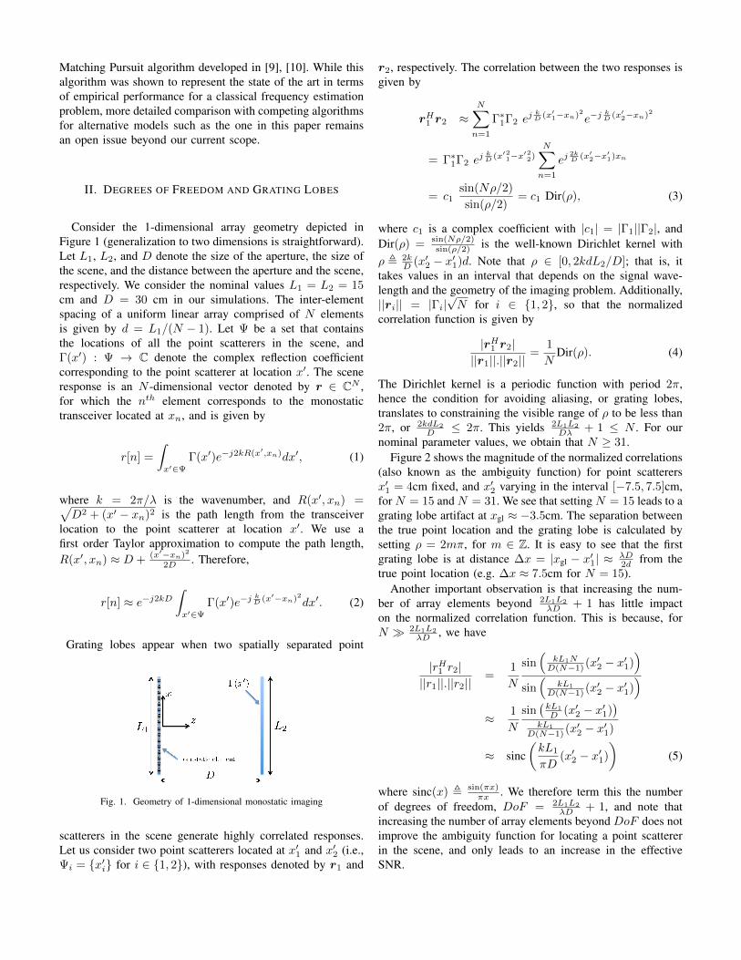
Consider the 1-dimensional array geometry depicted inFigure 1 (generalization to two dimensions is straightforward).Let L1, L2, and D denote the size of the aperture, the size ofthe scene, and the distance between the aperture and the scene,respectively. We consider the nominal values L1 = L2 = 15cm and D = 30 cm in our simulations. The inter-elementspacing of a uniform linear array comprised of N elementsis given by d = L1/(N − 1). Let Ψ be a set that containsthe locations of all the point scatterers in the scene, andΓ(x′) : Ψ → C denote the complex reflection coefficientcorresponding to the point scatterer at location x′. The sceneresponse is an N -dimensional vector denoted by r ∈ CN ,for which the nth element corresponds to the monostatictransceiver located at xn, and is given by
r[n] =
∫x′∈Ψ
Γ(x′)e−j2kR(x′,xn)dx′, (1)
where k = 2π/λ is the wavenumber, and R(x′, xn) =√D2 + (x′ − xn)2 is the path length from the transceiver
location to the point scatterer at location x′. We use afirst order Taylor approximation to compute the path length,R(x′, xn) ≈ D + (x′−xn)2
2D . Therefore,
r[n] ≈ e−j2kD∫x′∈Ψ
Γ(x′)e−jkD (x′−xn)2dx′. (2)
Grating lobes appear when two spatially separated point
Fig. 1. Geometry of 1-dimensional monostatic imaging
scatterers in the scene generate highly correlated responses.Let us consider two point scatterers located at x′1 and x′2 (i.e.,Ψi = {x′i} for i ∈ {1, 2}), with responses denoted by r1 and
r2, respectively. The correlation between the two responses isgiven by
rH1 r2 ≈N∑n=1
Γ∗1Γ2 ej kD (x′1−xn)2e−j
kD (x′2−xn)2
= Γ∗1Γ2 ej kD (x′21−x
′22)
N∑n=1
ej2kD (x′2−x
′1)xn
= c1sin(Nρ/2)
sin(ρ/2)= c1 Dir(ρ), (3)
where c1 is a complex coefficient with |c1| = |Γ1||Γ2|, andDir(ρ) = sin(Nρ/2)
sin(ρ/2) is the well-known Dirichlet kernel withρ , 2k
D (x′2 − x′1)d. Note that ρ ∈ [0, 2kdL2/D]; that is, ittakes values in an interval that depends on the signal wave-length and the geometry of the imaging problem. Additionally,||ri|| = |Γi|
√N for i ∈ {1, 2}, so that the normalized
correlation function is given by
|rH1 r2|||r1||.||r2||
=1
NDir(ρ). (4)
The Dirichlet kernel is a periodic function with period 2π,hence the condition for avoiding aliasing, or grating lobes,translates to constraining the visible range of ρ to be less than2π, or 2kdL2
D ≤ 2π. This yields 2L1L2
Dλ + 1 ≤ N . For ournominal parameter values, we obtain that N ≥ 31.
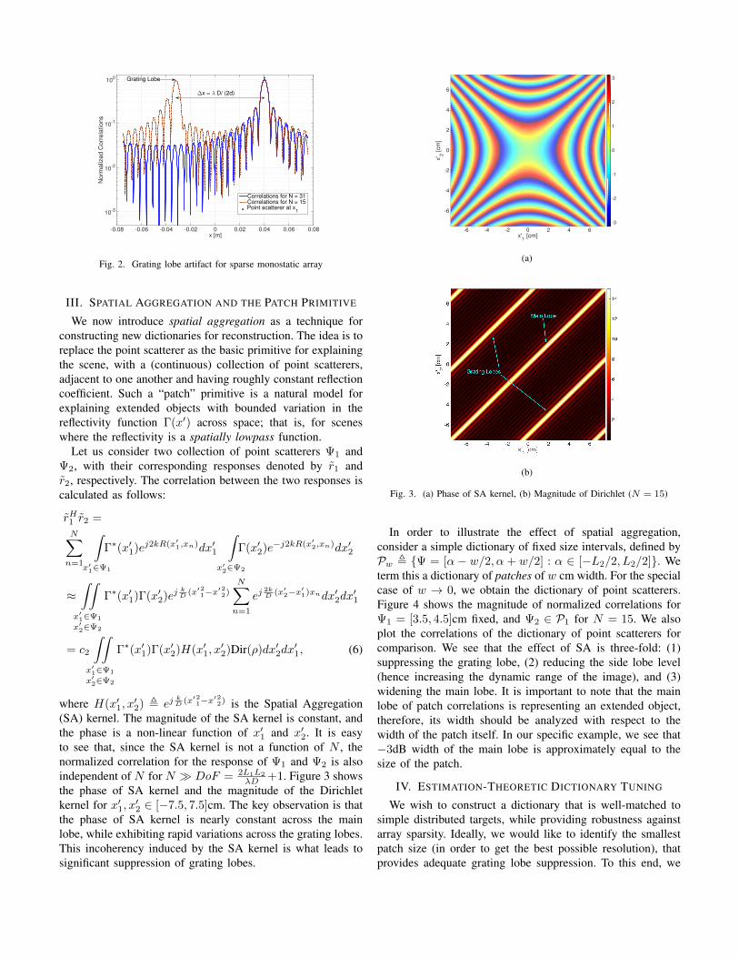
Figure 2 shows the magnitude of the normalized correlations(also known as the ambiguity function) for point scatterersx′1 = 4cm fixed, and x′2 varying in the interval [−7.5, 7.5]cm,for N = 15 and N = 31. We see that setting N = 15 leads to agrating lobe artifact at xgl ≈ −3.5cm. The separation betweenthe true point location and the grating lobe is calculated bysetting ρ = 2mπ, for m ∈ Z. It is easy to see that the firstgrating lobe is at distance ∆x = |xgl − x′1| ≈ λD
2d from thetrue point location (e.g. ∆x ≈ 7.5cm for N = 15).
Another important observation is that increasing the num-ber of array elements beyond 2L1L2
λD + 1 has little impacton the normalized correlation function. This is because, forN � 2L1L2
λD , we have
|rH1 r2|||r1||.||r2||
=1
N
sin(
kL1ND(N−1) (x′2 − x′1)
)sin(
kL1
D(N−1) (x′2 − x′1))
≈ 1
N
sin(kL1
D (x′2 − x′1))
kL1
D(N−1) (x′2 − x′1)
≈ sinc(kL1
πD(x′2 − x′1)
)(5)
where sinc(x) , sin(πx)πx . We therefore term this the number
of degrees of freedom, DoF = 2L1L2
λD + 1, and note thatincreasing the number of array elements beyond DoF does notimprove the ambiguity function for locating a point scattererin the scene, and only leads to an increase in the effectiveSNR.
x [m]-0.08 -0.06 -0.04 -0.02 0 0.02 0.04 0.06 0.08
No
rma
lize
d C
orr
ela
tio
ns
10-3
10-2
10-1
100
Correlations for N = 31Correlations for N = 15Point scatterer at x
1
∆x = λ D/ (2d)
Grating Lobe
Fig. 2. Grating lobe artifact for sparse monostatic array
III. SPATIAL AGGREGATION AND THE PATCH PRIMITIVE
We now introduce spatial aggregation as a technique forconstructing new dictionaries for reconstruction. The idea is toreplace the point scatterer as the basic primitive for explainingthe scene, with a (continuous) collection of point scatterers,adjacent to one another and having roughly constant reflectioncoefficient. Such a “patch” primitive is a natural model forexplaining extended objects with bounded variation in thereflectivity function Γ(x′) across space; that is, for sceneswhere the reflectivity is a spatially lowpass function.
Let us consider two collection of point scatterers Ψ1 andΨ2, with their corresponding responses denoted by r1 andr2, respectively. The correlation between the two responses iscalculated as follows:
rH1 r2 =N∑n=1
∫x′1∈Ψ1
Γ∗(x′1)ej2kR(x′1,xn)dx′1
∫x′2∈Ψ2
Γ(x′2)e−j2kR(x′2,xn)dx′2
≈∫∫
x′1∈Ψ1
x′2∈Ψ2
Γ∗(x′1)Γ(x′2)ejkD (x′21−x
′22)
N∑n=1
ej2kD (x′2−x
′1)xndx′2dx
′1
= c2
∫∫x′1∈Ψ1
x′2∈Ψ2
Γ∗(x′1)Γ(x′2)H(x′1, x′2)Dir(ρ)dx′2dx
′1, (6)
where H(x′1, x′2) , ej
kD (x′21−x
′22) is the Spatial Aggregation
(SA) kernel. The magnitude of the SA kernel is constant, andthe phase is a non-linear function of x′1 and x′2. It is easyto see that, since the SA kernel is not a function of N , thenormalized correlation for the response of Ψ1 and Ψ2 is alsoindependent of N for N � DoF = 2L1L2
λD +1. Figure 3 showsthe phase of SA kernel and the magnitude of the Dirichletkernel for x′1, x
′2 ∈ [−7.5, 7.5]cm. The key observation is that
the phase of SA kernel is nearly constant across the mainlobe, while exhibiting rapid variations across the grating lobes.This incoherency induced by the SA kernel is what leads tosignificant suppression of grating lobes.
x'1 [cm]
-6 -4 -2 0 2 4 6
x' 2
[cm
]
-6
-4
-2
0
2
4
6
-3
-2
-1
0
1
2
3
(a)
(b)
Fig. 3. (a) Phase of SA kernel, (b) Magnitude of Dirichlet (N = 15)
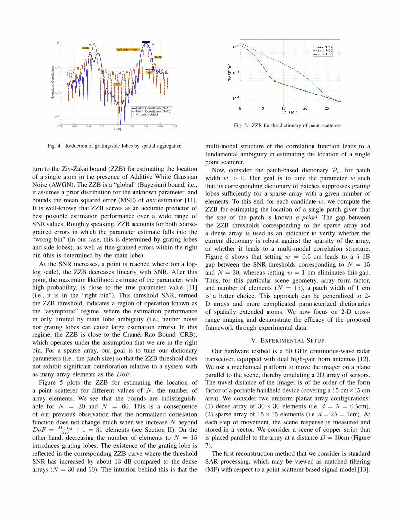
In order to illustrate the effect of spatial aggregation,consider a simple dictionary of fixed size intervals, defined byPw , {Ψ = [α − w/2, α + w/2] : α ∈ [−L2/2, L2/2]}. Weterm this a dictionary of patches of w cm width. For the specialcase of w → 0, we obtain the dictionary of point scatterers.Figure 4 shows the magnitude of normalized correlations forΨ1 = [3.5, 4.5]cm fixed, and Ψ2 ∈ P1 for N = 15. We alsoplot the correlations of the dictionary of point scatterers forcomparison. We see that the effect of SA is three-fold: (1)suppressing the grating lobe, (2) reducing the side lobe level(hence increasing the dynamic range of the image), and (3)widening the main lobe. It is important to note that the mainlobe of patch correlations is representing an extended object,therefore, its width should be analyzed with respect to thewidth of the patch itself. In our specific example, we see that−3dB width of the main lobe is approximately equal to thesize of the patch.
IV. ESTIMATION-THEORETIC DICTIONARY TUNING
We wish to construct a dictionary that is well-matched tosimple distributed targets, while providing robustness againstarray sparsity. Ideally, we would like to identify the smallestpatch size (in order to get the best possible resolution), thatprovides adequate grating lobe suppression. To this end, we
x [m]-0.08 -0.06 -0.04 -0.02 0 0.02 0.04 0.06 0.08
Norm
aliz
ed C
orr
ela
tions
10-3
10-2
10-1
100
Patch Correlation (N=15)Point Correlation (N=15)Ψ
1 patch object
4.5dB-3dB width ≈ 1cm
1cm
10dB
10dB
Fig. 4. Reduction of grating/side lobes by spatial aggregation
turn to the Ziv-Zakai bound (ZZB) for estimating the locationof a single atom in the presence of Additive White GaussianNoise (AWGN). The ZZB is a “global” (Bayesian) bound, i.e.,it assumes a prior distribution for the unknown parameter, andbounds the mean squared error (MSE) of any estimator [11].It is well-known that ZZB serves as an accurate predictor ofbest possible estimation performance over a wide range ofSNR values. Roughly speaking, ZZB accounts for both coarse-grained errors in which the parameter estimate falls into the“wrong bin” (in our case, this is determined by grating lobesand side lobes), as well as fine-grained errors within the rightbin (this is determined by the main lobe).
As the SNR increases, a point is reached where (on a log-log scale), the ZZB decreases linearly with SNR. After thispoint, the maximum likelihood estimate of the parameter, withhigh probability, is close to the true parameter value [11](i.e., it is in the “right bin”). This threshold SNR, termedthe ZZB threshold, indicates a region of operation known asthe “asymptotic” regime, where the estimation performancein only limited by main lobe ambiguity (i.e., neither noisenor grating lobes can cause large estimation errors). In thisregime, the ZZB is close to the Cramer-Rao Bound (CRB),which operates under the assumption that we are in the rightbin. For a sparse array, our goal is to tune our dictionaryparameters (i.e., the patch size) so that the ZZB threshold doesnot exhibit significant deterioration relative to a system withas many array elements as the DoF .
Figure 5 plots the ZZB for estimating the location ofa point scatterer for different values of N , the number ofarray elements. We see that the bounds are indistinguish-able for N = 30 and N = 60. This is a consequenceof our previous observation that the normalized correlationfunction does not change much when we increase N beyondDoF = 2L1L2
λD + 1 = 31 elements (see Section II). On theother hand, decreasing the number of elements to N = 15introduces grating lobes. The existence of the grating lobe isreflected in the corresponding ZZB curve where the thresholdSNR has increased by about 13 dB compared to the densearrays (N = 30 and 60). The intuition behind this is that the
Fig. 5. ZZB for the dictionary of point-scatterers
multi-modal structure of the correlation function leads to afundamental ambiguity in estimating the location of a singlepoint scatterer.
Now, consider the patch-based dictionary Pw for patchwidth w > 0. Our goal is to tune the parameter w suchthat its corresponding dictionary of patches suppresses gratinglobes sufficiently for a sparse array with a given number ofelements. To this end, for each candidate w, we compute theZZB for estimating the location of a single patch given thatthe size of the patch is known a priori. The gap betweenthe ZZB thresholds corresponding to the sparse array anda dense array is used as an indicator to verify whether thecurrent dictionary is robust against the sparsity of the array,or whether it leads to a multi-modal correlation structure.Figure 6 shows that setting w = 0.5 cm leads to a 6 dBgap between the SNR thresholds corresponding to N = 15and N = 30, whereas setting w = 1 cm eliminates this gap.Thus, for this particular scene geometry, array form factor,and number of elements (N = 15), a patch width of 1 cmis a better choice. This approach can be generalized to 2-D arrays and more complicated parameterized dictionariesof spatially extended atoms. We now focus on 2-D cross-range imaging and demonstrate the efficacy of the proposedframework through experimental data.
V. EXPERIMENTAL SETUP
Our hardware testbed is a 60 GHz continuous-wave radartransceiver, equipped with dual high-gain horn antennas [12].We use a mechanical platform to move the imager on a planeparallel to the scene, thereby emulating a 2D array of sensors.The travel distance of the imager is of the order of the formfactor of a portable handheld device (covering a 15 cm×15 cmarea). We consider two uniform planar array configurations:(1) dense array of 30 × 30 elements (i.e. d = λ = 0.5cm),(2) sparse array of 15× 15 elements (i.e. d = 2λ = 1cm). Ateach step of movement, the scene response is measured andstored in a vector. We consider a scene of copper strips thatis placed parallel to the array at a distance D = 30cm (Figure7).
The first reconstruction method that we consider is standardSAR processing, which may be viewed as matched filtering(MF) with respect to a point scatterer based signal model [13].

(a)
(b)
Fig. 6. ZZB for estimating the location of a single patch in the dictionary of(a) patches of size w = 0.5 cm (b) patches of size w = 1 cm.
Fig. 7. Experimental data collection using 60 GHz radar system.
The second approach is based on computing the correlation ofthe measured response with the responses of 1cm×1cm squarepatches; that is, the collection of patches obtained by slidinga 1cm × 1cm window over the entire scene. We refer to thisapproach as patch-based MF.
Figure 8 (left column) show the results of point-based MF.We see that grating lobes lead to significant deteriorationin image quality for the sparse array. Figure 8 (right col-umn) shows the result of patch-based MF. We see significantimprovement in the image quality, in terms of suppressingthe grating lobes and increasing the dynamic range (e.g. thehorizontal strip at the bottom of the scene becomes visible forthe dense array deployment). In the next section, we investi-gate a new technique for image reconstruction that leveragesthe “sparse representation” of the scene in the dictionary ofpatches. This parsimonious signal model, with appropriatelydesigned estimation algorithms, allows us to “super-resolve”
beyond the limits of conventional radar theory [14].
Point MF: dense array
Point MF: sparse array Patch MF: sparse array
Patch MF: dense array
x [m]-0.1 -0.08 -0.06 -0.04 -0.02 0 0.02 0.04 0.06 0.08 0.1
y [
m]
-0.1
-0.08
-0.06
-0.04
-0.02
0
0.02
0.04
0.06
0.08
0.1Point MF: 30x30 array
0.05
0.1
0.15
0.2
0.25
0.3
0.35
15cm
✦ x � 15cm
x [m]-0.1 -0.08 -0.06 -0.04 -0.02 0 0.02 0.04 0.06 0.08 0.1
y [
m]
-0.1
-0.08
-0.06
-0.04
-0.02
0
0.02
0.04
0.06
0.08
0.1Point MF: 15x15 array
0.02
0.04
0.06
0.08
0.1
0.12
0.14
0.16
✁ x ✂ 7.5cm
Fig. 8. Point-based v.s. patch-based matched filtering
VI. SPARSE RECONSTRUCTION
We formulate image formation as sparse reconstruction [15],approximating the scene response by a linear combinationof a few patch responses from our previously constructeddictionary D. To this end, we use a greedy iterative algorithmnamed Newtonized Orthogonal Matching Pursuit (NOMP) [9],[10], which is a generalization of the well-known OrthogonalMatching Pursuit (OMP) [16] to a continuously parametrizedovercomplete basis using Newton refinements. We note thatin [9], [10], the NOMP algorithm has been applied to es-timation of frequencies in a mixture of sinusoids, however,the algorithm is applicable for sparse approximation in anycontinuously parametrized overcomplete dictionary. Greedyiterative approaches (e.g., OMP and NOMP) are particularlyattractive due to their low computational complexity and easeof implementation [15].
For a scene containing K patches, the overall response ismodeled as
y =
K∑i=1
gαi rαi + z, (7)
where gαi ∈ C denotes the complex gain for ith patch, andz ∼ CN (0, σ2IN ) is the AWGN. We now present a high-level description of NOMP for sparse recovery in the radarimaging problem. Let Λ be the set of detected patches. Ineach iteration of the algorithm, an atom that yields the greatestimprovement in the approximation quality is identified andadded to Λ. After that, a cyclic refinement step is applied toall the atoms in Λ (i.e., the atoms that have been estimatedin the previous iterations), therefore giving them a chance tore-evaluate their estimates to incorporate the effect of newly

detected atom. We do not make a priori assumptions on thenumber of patches, and set the stopping criterion based onthe relative energy reduction of the residual signal (i.e., theportion of the signal not explained by the currently estimatedset of patches). We stop looking for further patches whenthe relative energy reduction of the residual goes below athreshold, denoted by ε. The iterative sparse reconstructionalgorithm is stated as follows:
1) Let q0 = y, εq0 = ||q0||2, and loop counter i← 1.
2) Find λ = arg maxβ{|qHi−1rβ |
||qi−1||.||rβ ||: rβ ∈ D}. Set
gλ =(rHλ qi−1)
||rλ||2 , and update Λ← Λ ∪ {(λ, gλ)}.3) Cyclicly refine centers/gains for all the patches in Λ.4) Update all gains by least squares for best approximation
of y with the atoms chosen so far.5) Find the new residual qi = y −
∑λ∈Λ
gλrλ, and compute
its energy εqi = ||qi||2.6) If |εqi − εqi−1
|/εq0 > ε, then set i ← i + 1, and goback to Step 2, otherwise, declare Λ as the output ofthe program.
Figure 9 shows the result of patch detection algorithm forthe same scene of copper strips, with only 15×15 equispacedemulated array elements (sparse array). The dictionary Dcontains all the 1.5cm×1.5cm square patches. We see that thealgorithm is able to detect the horizontal strip at the bottomof the scene, despite the sparsity of the array, which is asignificant improvement over the MF processing results inFigure 8.
Fig. 9. Image reconstruction using NOMP algorithm in the sparse arrayconfiguration. The patch sizes are fixed (1.5cm×1.5cm), and we only refinethe location of patches.
VII. GENERALIZATIONS
We now briefly discuss potential avenues for generalizingthe proposed framework. In the construction of the dictionaryof spatially extended atoms, we explicitly incorporate informa-tion about the array geometry in computing the response foreach atom. This approach allows for the design of a dictionarythat is well-matched to both the geometry of the array, and thenature of the scene being imaged, and can be easily extendedto other settings, such as non-uniform arrays.
Dynamic Dictionaries: One of the problems associatedwith scene-based dictionary design is that the number of atomsin the dictionary may become excessively large in order tocapture various shapes and sizes of the targets in the scene.This may lead to computational bottlenecks, especially forreal-time applications. One approach to alleviate this problemis to construct a dynamic dictionary by bootstrapping from abase dictionary characterized with a few parameters, with a rel-atively small number of atoms. Additional atoms could then beadded to this base dictionary during image reconstruction. Forexample, the dictionary of fixed-size square patches employedin Section VI can be augmented by allowing modification ofpatch sizes to better approximate the response to a given scene.This is easily accomplished by refining the width of patchesalong with their centers and gains in Step (3) of the NOMPalgorithm. Figure 10 shows the output of NOMP where westart with the dictionary of 1.5cm×1.5cm patches as the base,and then refine the sizes of the detected patches throughoutthe reconstruction process.
Fig. 10. Image reconstruction using NOMP algorithm in the sparse arrayconfiguration. We refine both the location and size of rectangular patches.
As another example, consider a dictionary of circularpatches. Figure 11 shows the output of NOMP algorithmwhere we use the collection of 1cm radius atoms as thebase dictionary, but then allow for both center and radiusrefinements. We see that the general structure of the sceneis reflected in the image, including the horizontal strip at thebottom of the scene. An advantage of the circular dictionaryis that the spatial size of the atoms is controlled by asingle parameter (radius), hence dynamic adaptation is morecomputationally efficient compared to reconstruction using adictionary of square patches.
VIII. CONCLUSIONS
We have shown that short-range radar imaging requires newmodels that account for scene and transceiver geometry, aswell as the number of transceiver elements. For sparse arrays,the patch-based models introduced here suppress grating lobes,while being compatible with the spatially lowpass nature oftypical scenes. An important topic for future work, especiallyfor sparse arrays, is to extract and employ Doppler informationas well.
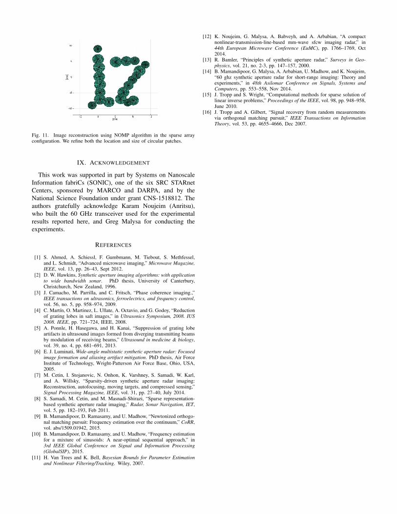
Fig. 11. Image reconstruction using NOMP algorithm in the sparse arrayconfiguration. We refine both the location and size of circular patches.
IX. ACKNOWLEDGEMENT
This work was supported in part by Systems on NanoscaleInformation fabriCs (SONIC), one of the six SRC STARnetCenters, sponsored by MARCO and DARPA, and by theNational Science Foundation under grant CNS-1518812. Theauthors gratefully acknowledge Karam Noujeim (Anritsu),who built the 60 GHz transceiver used for the experimentalresults reported here, and Greg Malysa for conducting theexperiments.
REFERENCES
[1] S. Ahmed, A. Schiessl, F. Gumbmann, M. Tiebout, S. Methfessel,and L. Schmidt, “Advanced microwave imaging,” Microwave Magazine,IEEE, vol. 13, pp. 26–43, Sept 2012.
[2] D. W. Hawkins, Synthetic aperture imaging algorithms: with applicationto wide bandwidth sonar. PhD thesis, University of Canterbury,Christchurch, New Zealand, 1996.
[3] J. Camacho, M. Parrilla, and C. Fritsch, “Phase coherence imaging.,”IEEE transactions on ultrasonics, ferroelectrics, and frequency control,vol. 56, no. 5, pp. 958–974, 2009.
[4] C. Martın, O. Martinez, L. Ullate, A. Octavio, and G. Godoy, “Reductionof grating lobes in saft images,” in Ultrasonics Symposium, 2008. IUS2008. IEEE, pp. 721–724, IEEE, 2008.
[5] A. Ponnle, H. Hasegawa, and H. Kanai, “Suppression of grating lobeartifacts in ultrasound images formed from diverging transmitting beamsby modulation of receiving beams,” Ultrasound in medicine & biology,vol. 39, no. 4, pp. 681–691, 2013.
[6] E. J. Luminati, Wide-angle multistatic synthetic aperture radar: Focusedimage formation and aliasing artifact mitigation. PhD thesis, Air ForceInstitute of Technology, Wright-Patterson Air Force Base, Ohio, USA,2005.
[7] M. Cetin, I. Stojanovic, N. Onhon, K. Varshney, S. Samadi, W. Karl,and A. Willsky, “Sparsity-driven synthetic aperture radar imaging:Reconstruction, autofocusing, moving targets, and compressed sensing,”Signal Processing Magazine, IEEE, vol. 31, pp. 27–40, July 2014.
[8] S. Samadi, M. Cetin, and M. Masnadi-Shirazi, “Sparse representation-based synthetic aperture radar imaging,” Radar, Sonar Navigation, IET,vol. 5, pp. 182–193, Feb 2011.
[9] B. Mamandipoor, D. Ramasamy, and U. Madhow, “Newtonized orthogo-nal matching pursuit: Frequency estimation over the continuum,” CoRR,vol. abs/1509.01942, 2015.
[10] B. Mamandipoor, D. Ramasamy, and U. Madhow, “Frequency estimationfor a mixture of sinusoids: A near-optimal sequential approach,” in3rd IEEE Global Conference on Signal and Information Processing(GlobalSIP), 2015.
[11] H. Van Trees and K. Bell, Bayesian Bounds for Parameter Estimationand Nonlinear Filtering/Tracking. Wiley, 2007.
[12] K. Noujeim, G. Malysa, A. Babveyh, and A. Arbabian, “A compactnonlinear-transmission-line-based mm-wave sfcw imaging radar,” in44th European Microwave Conference (EuMC), pp. 1766–1769, Oct2014.
[13] R. Bamler, “Principles of synthetic aperture radar,” Surveys in Geo-physics, vol. 21, no. 2-3, pp. 147–157, 2000.
[14] B. Mamandipoor, G. Malysa, A. Arbabian, U. Madhow, and K. Noujeim,“60 ghz synthetic aperture radar for short-range imaging: Theory andexperiments,” in 48th Asilomar Conference on Signals, Systems andComputers, pp. 553–558, Nov 2014.
[15] J. Tropp and S. Wright, “Computational methods for sparse solution oflinear inverse problems,” Proceedings of the IEEE, vol. 98, pp. 948–958,June 2010.
[16] J. Tropp and A. Gilbert, “Signal recovery from random measurementsvia orthogonal matching pursuit,” IEEE Transactions on InformationTheory, vol. 53, pp. 4655–4666, Dec 2007.
![Super-Resolution Imaging of MammogramsBased on the Super ... · hancement, such as denoising [22], deblurring [23], and super-resolution. The super-resolution convolutional neural](https://img.pdfslide.us/doc/110x75/5eb6748572cabc4dbb1b094d/super-resolution-imaging-of-mammogramsbased-on-the-super-hancement-such-as.jpg)


![Adaptive Large Scale Artifact Reduction in Edge-based ...€¦ · 1) Single-frame super-resolution, and 2) Multi-frame super-resolution. Single-frame super-resolution techniques [6],](https://img.pdfslide.us/doc/110x75/5f9d9a03c179a476d32d84a7/adaptive-large-scale-artifact-reduction-in-edge-based-1-single-frame-super-resolution.jpg)