Embed Size (px)
Citation preview
New Method for Analytical Photovoltaic Parameter Extraction
Javier Cubas
Santiago Pindado Assal Farrahi
Instituto de Microgravedad Ignacio da Riva Universidad Politecnica de Madrid
Madrid, Spain
Abstract— Correct modeling of the equivalent circuits regarding solar cell and panels is today an essential tool for power optimization. However, the parameter extraction of those circuits is still a quite difficult task that normally requires both experimental data and calculation procedures, generally not available to the normal user. This paper presents a new analytical method that easily calculates the equivalent circuit parameters from the data that manufacturers usually provide. The analytical approximation is based on a new methodology, since methods developed until now to obtain the aforementioned equivalent circuit parameters from manufacturer's data have always been numerical or heuristic. Results from the present method are as accurate as the ones resulting from other more complex (numerical) existing methods in terms of calculation process and resources.
Keywords-component; Solar panel; electric circuit; parameters.
solar cell; equivalent
I. INTRODUCTION
Photovoltaic energy is a growing industry available to an increasing number of users. The average user has changed within the past years, currently is not linked to any research or engineering project and does not have the ability or equipment to perform tests with solar panels. Nevertheless, a quite deep knowledge of the solar cells/panels behavior remains highly desirable to maximize power extraction. This knowledge is usually based on equivalent circuit modeling of the mentioned solar cells/panels from experimental results or manufacturers' data. In any case, to obtain this circuit, that is, to extract the equivalent circuit parameters, a complicated process is required. Existing numerical methods to obtain the mentioned circuit parameters from the manufacturer's data are iterative and non-straight forward methods. The aim of the present work is to develop a new analytical and non-iterative method that easily calculates the equivalent circuit parameters from manufacturer data. The calculated equivalent electric circuit accurately reproduces the I-V (current-voltage) curve of the panel. The proposed analytical method could be a useful tool for different applications such as power extraction optimization, solar panels selection, or development of new MPPT (Maximum Peak Power Tracking) methods.
II. EQUIVALENT CIRCUIT
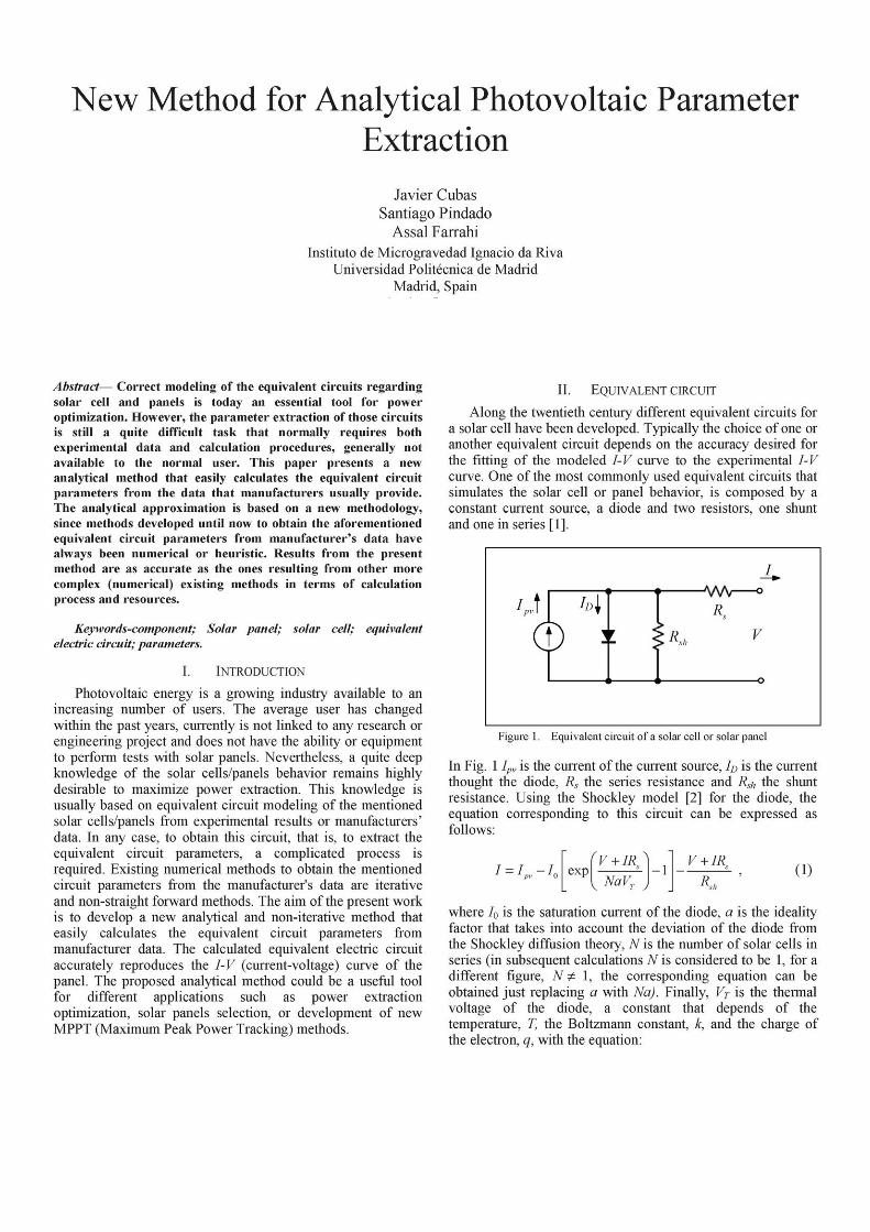
Along the twentieth century different equivalent circuits for a solar cell have been developed. Typically the choice of one or another equivalent circuit depends on the accuracy desired for the fitting of the modeled I-V curve to the experimental I-V curve. One of the most commonly used equivalent circuits that simulates the solar cell or panel behavior, is composed by a constant current source, a diode and two resistors, one shunt and one in series [1].
Figure 1. Equivalent circuit of a solar cell or solar panel
In Fig. 1 Ipy is the current of the current source, ID is the current thought the diode, Rs the series resistance and Rsh the shunt resistance. Using the Shockley model [2] for the diode, the equation corresponding to this circuit can be expressed as follows:
/ = / -L pv 0
exp
rV + IR:^
v NaVT j - 1 v + iR
(1)
where I0 is the saturation current of the diode, a is the ideality factor that takes into account the deviation of the diode from the Shockley diffusion theory, N is the number of solar cells in series (in subsequent calculations N is considered to be 1, for a different figure, N^ 1, the corresponding equation can be obtained just replacing a with Na). Finally, VT is the thermal voltage of the diode, a constant that depends of the temperature, T, the Boltzmann constant, k, and the charge of the electron, q, with the equation:

v^ (2)
The equivalent circuit model on Fig. 1 contains five unknown parameters: Ipv, Rs, Rsh, I0 and a; to be estimated from experimental data of the I-V curve.
III. PARAMETER IDENTIFICATION
In general, the main disadvantage of these equivalent circuit models is the determination of the parameters. This determination often gives inaccurate results because of the great simplifications made in equations [3]. Most of the not simplified methods are iterative or imply methods for solving multiple equations like the minimum least squares method [4-7]. However, as discussed in this section, an adequate approximation to the problem, with justified and appropriate simplification, allows to reduce it to a series of decoupled equations, so the circuit parameters can be then determined in a simple, precise, and noniterative way.
A. Boundary conditions and available information
As discussed in Section II, the equivalent circuit selected in the present work requires the determination of five parameters for representing the I-V curve. This implies that at least 5 boundary conditions of the curve must be identified. These boundary conditions can be obtained from experimental tests or from the information provided by the manufacturer. This second option is more interesting from the standpoint of cost savings, but has the problem that the manufacturer does not always provide comprehensive information with regard to the I-V curve.
Most solar cell manufacturers usually provide the values of at least three points of the I-V curve. Open circuit (Voc; 0), short circuit (0; Isc) and maximum power point (Imp, Vmp). That provides four known data and four boundary conditions. Nevertheless, these four equations are not enough to identify the five mentioned parameters, for this reason, in absence of more information, one of the five parameters has to be estimated. The value of the diode constant, a, is normally within the bracket [1, 1.5] for a single junction solar cell [4]. Some authors [4], [8], [9] propose to give it an initial value in order to reduce the number of parameters to four. This allows to obtain a full set of parameters that satisfies the boundary conditions of the manufacturer. The estimated value of a will affect the curvature of the I-V curve, so, if further information of the curve is available, its value may be adjusted in order to obtain a better fit.
B. Equations from boundary conditions
In this subsection the equations for the four boundary conditions usually provided by the manufacturer will be simplified and adequately combined to obtain a set of decoupled equations. All simplifications have been made taking into account the value of other equivalent circuit parameters taken from different authors [10-12], in order to determine the order of magnitude of the different terms in the equations.
Equation (1) at short circuit point can be rewritten as:
* sc * pv '-a exp (l„R.
I aVT
I«R.
and simplified to [8], [13]:
J = Rsh + Rs J
pv u s,
(3)
(4)
• Also, at open circuit point, equation (1) can be rewritten as:
o = /„-/„ ''£'• R, (5)
that, using (4), can be simplified to [14], [15]:
h = - ^ — • (6)
RA exp aVT
• Finally, equation (1) can be derived, at maximum power point, to:
I =1 -h mp pv (J
exp V +1 R
mp mp s I i
aVT
V +1 R mp mp s (H\
R.i,
that, using (4) and (6), can be simplified to:
sc sc
V -R I j I r oc s sc
R„ exp
V +1 R -V mp mp s oc
V +1 R — T R mp mp s sc s
(8)
• The condition of zero derivative for the power at maximum power point can be mathematically expressed as [10]:
dv 7 v ~ mp ' mp
m\
V (9)
Using the above condition in (1), introducing (4), (6) and (8) and then simplifying, it is possible to obtain:
"VTVmp{2Imp-Isc)
[r*t„+rAI~-I-)){v-*-I-*R')-aVT(v-*I*-v~I-») (10)
= exp V +1 R -V
mp mp s oc
aVT
Finally, from (8) and (10) a more convenient expression of the shunt resistor, Rsh can be derived:
{Vmp-LpRs)(Vmp-Rs{isc-Lp)-aVT,
(V -I R)(I -I )-aVTI \ mp mp s } \ sc mp } I mp
C. Resolution process
In the previous section four decoupled equations that solve the calculation of the remaining four parameters in a linear way
have been derived. The process to calculate the parameters of the equivalent circuit, from the four boundary conditions given at a certain temperature, is then as follows:
• Estimate the parameter a. Its value is supposed to be in the bracket [1, 1.5]. For a better approach existing data referred to the considered cell type, may be considered.
• Obtain the value of inform equation (10).
• Obtain the value of Rsh form equation (11).
• Obtain the value of I0 form equation (6).
• Obtain the value of Ipv form equation (4).
If additional information about the I-V curve is available, it can be used to re-estimate the parameter a.
IV. COMPARISON WITH OTHER METHODS
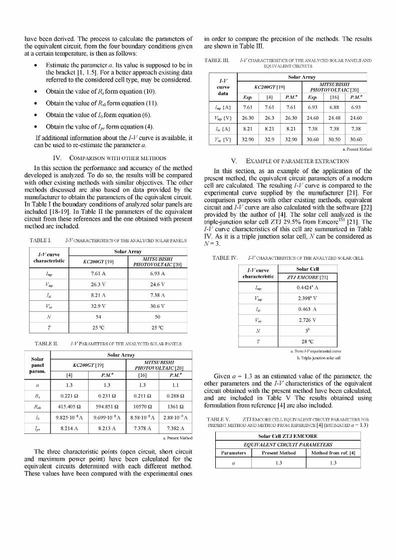
In this section the performance and accuracy of the method developed is analyzed. To do so, the results will be compared with other existing methods with similar objectives. The other methods discussed are also based on data provided by the manufacturer to obtain the parameters of the equivalent circuit. In Table I the boundary conditions of analyzed solar panels are included [18-19]. In Table II the parameters of the equivalent circuit from these references and the one obtained with present method are included.
T A B L E I. I-V CHARACTERISTICS OF THE ANALYCED SOLAR PANELS
I-V curve characterist ic
Imp
' mp
±sc
v„
N
T
Solar Ar r ay
KC200GT [19]
7.61 A
26.3 V
8.21 A
32.9 V
54
25 °C
MITSUBISHI PHOTOVOLTAIC [20]
6.93 A
24.6 V
7.38 A
30.6 V
50
25 °C
TABLE II. I-V PARAMETERS OF THE ANAL YCED SOLAR PANELS
111
a
Rs
Rsh
h
ipv
Solar Ar r ay
KC200GT [19]
[4]
1.3
0.221 Q
415.405 Q
9.825-10~8A
8.214 A
P.M."
1.3
0.231 il
594.851 il
9.699-10~8A
8.213 A
MITSUBISHI PHOTOVOLTAIC [20]
[16]
1.3
0.211 Q
10570 Q
8.58-10~8A
7.378 A
P.M."
1.1
0.288 il
1361 il
2.88-10_9A
7.382 A
a. Present Method
The three characteristic points (open circuit, short circuit and maximum power point) have been calculated for the equivalent circuits determined with each different method. These values have been compared with the experimental ones
in order to compare the precision of the methods. The results are shown in Table III.
T A B L E III. I- V CHARACTERISTICS OF THE ANALYCED SOLAR PANELS AND EQUIVALENT CIRCUITS
I-V curve da ta
Imp {A}
Vmp {V}
he {A}
Voc{\}
Solar Ar r ay
KC200GT [19]
Exp.
7.61
26.30
8.21
32.90
[4]
7.61
26.3
8.21
32.9
P.M."
7.61
26.30
8.21
32.90
MITSUBISHI PHOTOVOLTAIC [20]
Exp.
6.93
24.60
7.38
30.60
[16]
6.88
24.48
7.38
30.50
P.M.11
6.93
24.60
7.38
30.60
a. Present Method
V. EXAMPLE OF PARAMETER EXTRACTION
In this section, as an example of the application of the present method, the equivalent circuit parameters of a modern cell are calculated. The resulting I-V curve is compared to the experimental curve supplied by the manufacturer [21]. For comparison purposes with other existing methods, equivalent circuit and I-V curve are also calculated with the software [22] provided by the author of [4]. The solar cell analyzed is the triple-junction solar cell ZTJ 29.5% from Emcore™ [21]. The I-V curve characteristics of this cell are summarized in Table IV. As it is a triple junction solar cell, N can be considered as N=7>.
T A B L E IV. I-V CHARACTERISTICS OF THE ANALYZED SOLAR CELL
I-V curve characterist ic
Imp
' mp
±sc
v„
N
T
Solar Cell
ZTJ EMCORE [21]
0.4424s A
2.398 aV
0.463 A
2.726 V
3b
28 °C
a. From I-V experimental curve
b. Triple-junction solar cell
Given a = 1.3 as an estimated value of the parameter, the other parameters and the I-V characteristics of the equivalent circuit obtained with the present method have been calculated, and are included in Table V The results obtained using formulation from reference [4] are also included.
T A B L E V. ZTJ EMCORE CELL EQUIVALENT CIRCUIT PARAMETERS FOR PRESENT METHOD AND METHOD FROM REFERENCE [4] (ESTIMATED a = 1.3)
Solar Cell Z T J E M C O R E
EQUIVALENT CIRCUIT PARAMETERS
Parameters
a
Present Method
1.3
Method from ref. [4]
1.3

Solar Cell ZTJ EMCORE
EQUIVALENT CIRCUIT PARAMETERS
Parameters
Rs
R.sh
h
ipx
Present Method
7.38- 1(T4 il
1238.21 il
9.249-10~13A
0.463 A
Method from ref. [4]
1 . 9 8 - l C i i
944.59 il
9.236-10~13A
0.463 A
The experimental I-V curve of the manufacturer and the I-V curves of the equivalent circuits obtained with the present method and method from reference [4] are shown in Fig. 2. The differences between experimental and estimated curves are also shown for both methods in the same figure.
0.5 /(A) O W H H K -O-O O O
0.4 --Eq. Circuit [4]
O Experimental 0 . 3 "H D |I Exp. -1 Eq. C. PM
A |I Exp. -1 Eq. C. [4]
0.2
0.1
• Eq Circuit PM
0 J M i t t f l ^ f l a a
0.020 AI (A)
- 0.015
- 0.010
- 0.005
0.000
comparison. The equivalent circuit has been calculated for values of parameters a within the bracket [1-1.5]. Using the procedure defined in Chapter III, Section C. For each set of parameters the value of the parameter RAISE has been calculated obtaining a minimum value for a = 1.1794, see Fig. 3.
RAISE 0.001
0.006
0.005
0.004
0.003
0.002
0.001
0
1
1 1 1
RMSE of Equivalent circuit
S_ r \ s \ ,
\ s > \ "*
-U - /
1.1 1.2 1.3 1.4 1.5 a
V(V)
Figure 3. RMSE of the equivalent circuit, calculated with present method, depending on the estimated value for the parameter a. ZTJ EMCORE solar
cells.
The parameters of the optimized equivalent circuit are included in Table VI. In Fig. 4 the experimental I-V curve of the manufacturer and the I-V curve of the optimized equivalent circuit obtained with the present method are shown, together with the difference between both curves.
Figure 2. Left scale: Experimental (manufacturer supplied) /-Kcurve. estimated curves with present method and method [4] for a = 1.3; Right scale: absolute differences between experimental and estimated I for both methods.
ZTJ EMCORE solar cells.
The simplicity of the method makes it a powerfull tool for multiple calculations of equivalent circuits, with different temperature and illumination conditions. Also, in presence of additional information about the I-V curve the method can be used to optimize the equivalent circuit, for example by obtaining the optimal value of a that minimizes the difference between experimental and calculated I-V curve. Varying the value of parameter a, the resulting I-V curve maintains the tree operating points but changes its curvature slightly. This particular manufacturer, Emcore, provides a complete experimental I-V curve of the solar cell analyzed. With this additional information it is possible to estimate a better value of parameter a, improving the fitting of the equivalent circuit behavior to the experimental I-V curve. To quantify the accuracy of the fitting, the root-mean-squared difference to the experimental results, RAISE:
TABLE VI. ZTJ EMCORE CELL EQUIVALENT CIRCUIT PARAMETERS FOR ESTIMATED a = 1 .1794
1 m
(12)
has been used previously by other authors [17]. In the above expression/, and/cai, are respectively the experimental current and the calculated current (from the equivalent circuit) at the same voltage level, and m is the number of points used in the
Solar Cell
ZTJ EMCORE
Parameters
a
Rs
R.sh
h
±P\
1.1794
5.7255-10~2£2
671.66 il
5.865M0~1 4A
0.46304 A
I-Vchar.
imp
" mp
isc
v„
N
0.4424 A
2.398 V
0.463 A
2.726 V
3

/(A) U.J T
0.4 --
0.3 --
U.Z "
o *
J i l l
Eq. Circuit PM a=l .3
Eq Circuit a=1.1794
0 Experimental
D |IExp. -IEq. C.|a-1.3
• |IExp. -IEq. C.|a=l. 1794
J y r JJ >-
r̂ -> "o
"1
n U
_
n n ,
0.020
AI(K)
-- 0.015
0.010
0.005
0.000
0 1 2 F ( V ) 3
Figure 4. Left scale: Experimental (manufacturer supplied) I-Vcurve. estimated for a = 1.3 and a = 1.1794; Right scale: absolute difference between
experimental and estimated I. ZTJ EMCORE solar cells.
VI. CONCLUSIONS
The aim of this work is to present an easy and accurate method to calculate the equivalent circuit parameters of a solar cell or solar panel from only the data that manufacturers usually provide. For that, an analytical method has been chosen. The analytical approximation to this particular problem is a novel approach, since methods developed until now to obtain the equivalent circuit parameters from manufacturer data have always been numerical or heuristic [18]. The result is a simple, non-iterative and straightforward method. Compared to similar methods from the available literature, the accuracy of the results seems to be high, the difference with experimental results being less than 1% in terms of current around the maximum power point. There are several possible applications for this method. From the authors' point of view, its simplicity and accuracy would make it interesting for end users with little calculation and testing resources. Also, the procedure described in the present work seems to be very appropriate for multiple calculations of equivalent circuits or determination of initial values for numerical methods.
REFERENCES
[1] M. Wolf and H. Rauschenbach, "Series resistance effects on solar cell measurements," Advanced Energy Conversion, vol. 3, pp. 455-479. 1963.
[2] W. Shocley, "The Theory of p-n Junctions in Semiconductors and p-n Junction Transistors.," Bell System TechnicalJournal, vol. 28, pp. 435-489, 1949.
[3] D. S. H. Chan and J. C. H. Phang, "Analytical methods for the extraction of solar-cell single- and double-diode model parameters from I-V characteristics," IEEE Transactions on Electron Devices, vol. 34, no. 2, pp. 286-293, Feb. 1987.
[4] M. G. Villalva, J. R. Gazoli, and E. R. Filho, "Modeling and circuit-based simulation of photovoltaic arrays," 2009 Brazilian Power Electronics Conference, pp. 1244-1254, Sep. 2009.
[5] A. H. Alqahtani, "A Simplified and Accurate Photovoltaic Module Parameters Extraction Approach using Matlab," Electrical Engineering, pp. 1748-1753, 2012.
[6] A. Orioli and A. Di Gangi, "A procedure to calculate the five-parameter model of crystalline silicon photovoltaic modules on the basis of the tabular performance data," Applied Energy, vol. 102, pp. 1160-1177, Feb. 2013.
[7] M. Averbukh, S. Lineykin, and A. Kuperman, "Obtaining small photovoltaic array operational curves for arbitrary cell temperatures and solar irradiation densities from standard conditions data I," Methodology, 2012.
[8] M. G. Villalva, J. R. Gazoli, and E. R. Filho, "Comprehensive Approach to Modeling and Simulation of Photovoltaic Arrays," IEEE Transactions on Power Electronics, vol. 24, no. 5, pp. 1198-1208, May 2009.
[9] S. Lineykin, "Five-Parameter Model of Photovoltaic Cell Based on STC Data and Dimensionless," Electrical engineering and electronics, pp. 1-5,2012.
[10] K. L. Kennerud, "Analysis of Perform- ance Degradation in," Ieee Transactions On Aerospace And Electronic Systems, no. 6, 1969.
[11] V. Lo Brano, A. Orioli, G. Ciulla, and A. Di Gangi, "An improved five-parameter model for photovoltaic modules," Solar Energy Materials and Solar Cells, vol. 94, no. 8, pp. 1358-1370, Aug. 2010.
[12] J. P. Charles, "A practical method of analysis of the current-voltage characteristics of solar cells," Solar Cells, vol. 4, pp. 169-178, 1981.
[13] D. Sera, R. Teodorescu, and P. Rodriguez, "PV panel model based on datasheet values," Electrical Engineering, no. 4, pp. 2392-2396, 2007.
[14] G. Walker, "Evaluating MPPT Converter Topologies Using a Matlab PV Model," Journal of Electrical & Electronics Engineering, Australia, vol. 21, no. l,pp. 49-55, 2001.
[15] W. Xiao, W. G. Dunford, and A. Capel, "A novel modeling method for photovoltaic cells," 2004 IEEE 35th Annual Power Electronics Specialists Conference (IEEE Cat. No.04CH37551), pp. 1950-1956, 2004.
[16] A. H. Alqahtani, "A Simplified and Accurate Photovoltaic Module Parameters Extraction Approach using Matlab," Industrial Electronics (ISIE), 2012 IEEE International Symposium on, 1748-1753, 2012.
[17] A. Askarzadeh and A. Rezazadeh, "Parameter identification for solar cell models using harmony search-based algorithms," Solar Energy, vol. 86, no. 11, pp. 3241-3249, Nov. 2012.
[18] M. C. Di Piazza and G. Vitale, Photovoltaic Sources. London: Springer London, 2013.
[19] Kyocera Solar Panels, http://www.kyocerasolar.com/ [20] Mitsubishi Electric Solar, http://www.mitsubishielectricsolar.com/ [21] Emcore, http://www.emcore.com/ [22] https://sites.google.com/site/mvillalva/pvmodel


![[Second Draft]One-diode photovoltaic model parameter](https://img.pdfslide.us/doc/110x75/61d546dc3a8ea93daa6d0915/second-draftone-diode-photovoltaic-model-parameter-.jpg)