Embed Size (px)
Citation preview
New generation of thermistor motor protection relays - CM-MSS rangeProtecting your motors from overheating
2 2CDC112213B0201
Benefits of the CM-MSS rangeRely on us wherever you need us
With ABB as a partner for the installation of your application you can be sure to have not only a competent partner regarding the safety of your application but as well a partner with a large variety of products which allows you to get all products by one supplier. Especially the assortment of electronic products and relays offers a bunch of innovative products for each specific customers' needs due to the large spectrum of innovative and cost saving products. In addition to provide cost effective solutions and a high functionality you can count on plenty of values like support wherever you are due to our global techn ical support or an easy to use product which allows a fast installation and startup.
Harsh environment protectionOur engineers thrive on the challenge to develop products that need to operate in the most difficult electrical, mechanical and environmental conditions. Our thermistor motor protection relays protect your application from overheating and therefore prevent motor damage ensuring your peace of mind. The new thermistor motor protection relays CM-MSS protect your application due to the coverage of many internationally valid approvals and markings and therefore ensure best quality and compliance to the most international safety standards. Additionally by installing a CM-MSS device you are in compliance with the latest version of the product standard DIN EN 60947-8:2013-07 and IEC/EN 60947-8 concerning control units for built-in thermal protection for rotating electrical machines.
Improve installation efficiencyIn everything we do, we think of the customer and the application first. Our engineers constantly look for ways to simplify the installation process by developing innovative product designs which facilitate the product assembly and avoid mounting errors and reduce maintaince cost.The CM-MSS range is easy to use due to the newest innovation: the possibility to distinquish between different operational states and faults. You can easily check the status of the application by reading the front-face LEDs. The excellent documentation in terms of data sheets, instruction sheets and the EPR catalog provides all necessary information to select, install and configure these products. By using the push-in variant of the CM-MSS range a fast wiring is possible while avoiding mounting errors. The completely tool free mounting and de-mounting simplifies the installation process as well. Adjustments can be done by the front faced DIP switches which are covered by the marker lable.
Reliable in harsh conditionsYou will find ABB control products in any application and corner of the world. They are in skyscrapers or windfarms, in offshore platforms or industrial areas which power the world. Approved by local and international standards. We believe in the strength of our brand and products - which is supported by our global service network to ensure your peace of mind.The ABB thermistor motor protection relays give you access to world wide markets and are approved by local and international standards for many applications such as industry, renewable energies, the marine sector and dangerous and explosive ATEX environments. At the same time, our customers can rely on ABB´s global technical support which is supported by our global service network to provide quick help when needed.
2CDC112213B0201 3
The reliable solution to protect your motors against overheating
FunctionalityMany motor protection devices protect motors from overheating and overload based on the motor current information. The real temperature though is not detected by these devices. This temperature in the thermal hot spots of a motor can be higher than expected due to – motor location in a high temperature area – or insufficient cooling.
To avoid this, motors should be protected against high temperatures. This can be done by measuring the temperature with PTC sensors in the motor windings and/or bearings and monitoring this signals with a CM-MSS thermistor motor protection relay.
High standards for application wherever you areThe new thermistor motor protection relay CM-MSS is already designed according the current product standards DIN EN 60947-8:2013-07 and IEC/EN 60947-8. In this product standard the dynamic interrupted wire detection is already mentioned.
ATEX approval for safe use in hazardous locationABB’s assortment of thermistor motor protection relays are also available with ATEX approval. Short-circuit detection as well as manual reset are essential.
Dynamic interrupted wire detectionDuring the operation the measuring circuit is permanently monitored by the device. If the resistance in the measuring circuit changes, the device recognizes on the basis of the velocity of change if there is an interrupted wire.
High EMC resistance to protect your applicationMotors and their cabling are typically used in a harsh industrial environment. Even strong disturbances from other devices like drives should not disturb the functionality of a motor protection device. By using the CM-MSS you do not need to differentiate anymore the length of the wires regarding the usage of shielded or unshielded wires.
Comfortable wiring for an easy to use productBeneath ensuring a good and reliable functionality, a product should also offer a comfortable wiring. All CM-MSS relays are available with two wiring technologies. – Double-chamber cage connection technology – Easy Connect Technology (Push-in)
Trouble shooting by status indication via LEDsThe thermistor motor protection relay is now able to distinguish between different causes of error and shows the error by a clear LED code.
4 2CDC112213B0201
Principle of thermistor motor protectionOne setup ensuring safety for your application
Direct temperature meausuringGenerally, motor damages caused by overload or overheating situations can be prevented in different ways. Compared to the indirect temperature measuring which monitors the current flowing into the motor, the temperature inside the motor could be measured by direct temperature measuring.This enables direct control and evaluation of the following operating conditions like: – Heavy duty starting – Increased switching frequency – Single phase operation – Phase unbalance – High ambient temperature – Insufficient cooling – Breaking operation
Therefore the consequences from overheating like abrasion as well as electrical failures can be prevented.The direct measuring principle is carried out by a combination of the thermistor motor protection relay and 3 PTC sensors which are installed directly in the motor by the manufacturer. Those 3 PTC sensors are placed directly at the thermal hotspots, the motor windings.
The thermistor motor protection relays of the CM-MSS range monitor the winding temperature of motors which have PTC temperature sensors equipped. These sensors are incorporated in the motor windings thus measuring the motor heat directly.
Monitoring the motorThe thermistor motor protection relay measures the resistance of the PTC sensors which reflects the internal motor temperature permanently. If the temperature in the motor windings rises excessively and reaches the nominal response temperature (NRT), the thermistor motor protection relay detects this situation and the output relay switches off.By doing so the motor contactor gets triggered and switches off the motor.As soon as the motor cools down and the temperature reaches the reset threshold it is possible to reset the thermistor motor protection relay. The yellow LED signals the possibility to reset with blinking with a high frequency.After the reset, the relay closes again thus triggering the motor contactor to re-start the motor.
CM-MSS functionality video
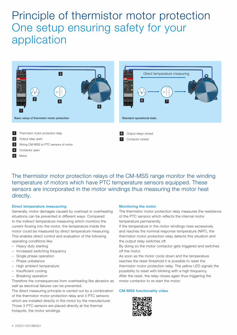
Basic setup of thermistor motor protection Standard operational state
1
3
24
5
6 7
1 Thermistor motor protection relay
2 Output relay open
3 Wiring CM-MSS to PTC sensors of motor
4 Contactor open
5 Motor
6 Output relays closed
7 Contactor closed
Direct temperature measuring
2CDC112213B0201 5
Technical overviewCharacteristics and features
Characteristics 1)
– Different types of contacts available – 1 x 2 c/o (SPDT) contacts – 2 x 1 c/o (SPDT) contact – 1 n/o and 1 n/c contact
– 1-2 measuring circuits – Different types of reset functions
– Automatic – Manual – Remote
– Rated control supply voltages – 24 V AC/DC – 24-240 V AC/DC – 110-130 V AC, 220-240 V AC
Features 1)
– Additional functions: – Dynamic interrupted wire detection – Short-circuit monitoring of the sensor circuit – Non-volatile fault storage – Single or sum evaluation
– Easy configuration via DIP switches – LEDs to distinguish between different failure causes – Screw connection technology or Easy Connect Technology
available – Test/Reset button available
1) Depending on device the characteristics vary, for detailled overview see page 7 “Selection table”
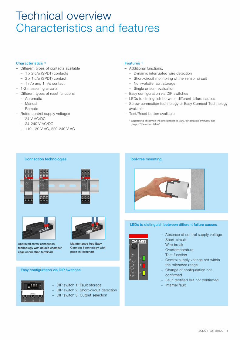
Maintenance free Easy Connect Technology with push-in terminals
Approved screw connection technology with double-chamber cage connection terminals
Easy configuration via DIP switches
LEDs to distinguish between different failure causes
Tool-free mountingConnection technologies
– Absence of control supply voltage – Short-circuit – Wire break – Overtemperature – Test function – Control supply voltage not within
the tolerance range – Change of configuration not
confirmed – Fault rectified but not confirmed – Internal fault – DIP switch 1: Fault storage
– DIP switch 2: Short-circuit detection – DIP switch 3: Output selection
6 2CDC112213B0201
Applicable all over the world according to highest standards for various segments
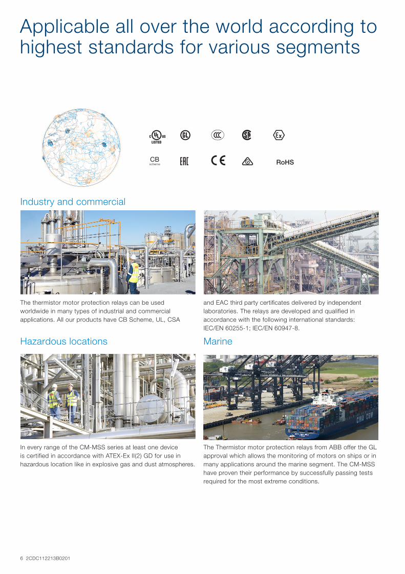
A C E F I
K R a b RoHS
The thermistor motor protection relays can be used worldwide in many types of industrial and commercial applications. All our products have CB Scheme, UL, CSA
Industry and commercial
In every range of the CM-MSS series at least one device is certified in accordance with ATEX-Ex II(2) GD for use in hazardous location like in explosive gas and dust atmospheres.
The Thermistor motor protection relays from ABB offer the GL approval which allows the monitoring of motors on ships or in many applications around the marine segment. The CM-MSS have proven their performance by successfully passing tests required for the most extreme conditions.
Hazardous locations Marine
and EAC third party certificates delivered by independent laboratories. The relays are developed and qualified in accordance with the following international standards: IEC/EN 60255-1; IEC/EN 60947-8.
2CDC112213B0201 7
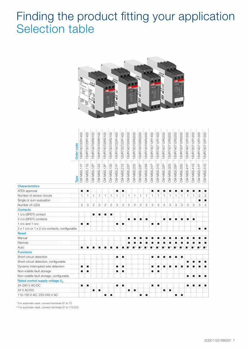
Finding the product fitting your applicationSelection table
Ord
er c
od
e
1SV
R74
0720
R14
00
1SV
R73
0720
R14
00
1SV
R74
0700
R01
00
1SV
R73
0700
R01
00
1SV
R74
0700
R21
00
1SV
R73
0700
R21
00
1SV
R74
0722
R14
00
1SV
R73
0722
R14
00
1SV
R74
0700
R02
00
1SV
R73
0700
R02
00
1SV
R74
0700
R22
00
1SV
R73
0700
R22
00
1SV
R74
0712
R14
00
1SV
R73
0712
R14
00
1SV
R74
0712
R02
00
1SV
R73
0712
R02
00
1SV
R74
0712
R22
00
1SV
R73
0712
R22
00
1SV
R74
0712
R12
00
1SV
R73
0712
R12
00
1SV
R74
0712
R13
00
1SV
R73
0712
R13
00
Typ
e
CM
-MS
S.1
1P
CM
-MS
S.1
1S
CM
-MS
S.1
2P
CM
-MS
S.1
2S
CM
-MS
S.1
3P
CM
-MS
S.1
3S
CM
-MS
S.2
1P
CM
-MS
S.2
1S
CM
-MS
S.2
2P
CM
-MS
S.2
2S
CM
-MS
S.2
3P
CM
-MS
S.2
3S
CM
-MS
S.3
1P
CM
-MS
S.3
1S
CM
-MS
S.3
2P
CM
-MS
S.3
2S
CM
-MS
S.3
3P
CM
-MS
S.3
3S
CM
-MS
S.4
1P
CM
-MS
S.4
1S
CM
-MS
S.5
1P
CM
-MS
S.5
1S
Characteristics
ATEX approval n n n n n n n n n n n n n n
Number of sensor circuits 1 1 1 1 1 1 1 1 1 1 1 1 1 1 1 1 1 1 1 1 2 2
Single or sum evaluation n n
Number of LEDs 3 3 2 2 2 2 3 3 2 2 2 2 3 3 3 3 3 3 3 3 3 3
Contacts
1 c/o (SPDT) contact n n n n
2 c/o (SPDT) contacts n n n n n n n n n n
1 n/c and 1 n/o n n n n n n
2 x 1 c/o or 1 x 2 c/o contacts, configurable n n
Reset
Manual n n n n n n n n n n n n n n
Remote n n n n n n n n n n n n n n
Auto n n n n n n n n n1) n1) n1) n1) n1) n1) n1) n1) n1) n1) n1) n1) n2) n2)
Functions
Short-circuit detection n n n n n n n n
Short-circuit detection, configurable n n n n
Dynamic interrupted wire detection n n n n n n n n n n n n n n
Non-volatile fault storage n n n n n n
Non-volatile fault storage, configurable n n n n
Rated control supply voltage US
24-240 V AC/DC n n n n n n n n n n
24 V AC/DC n n n n n n
110-130 V AC, 220-240 V AC n n n n n n
1) For automatic reset, connect terminals S1 to T2.2) For automatic reset, connect terminals S1 to 1T2/2T2.

Samaratel. +7 846 273 95 [email protected]
Yekaterinburgtel. +7 343 287 19 [email protected]
St. Petersburgtel. +7 812 327 [email protected]
Moscowtel. +7 495 641 [email protected]
Helsinkitel. +358 9 540 [email protected]
Vilniustel. +370 5 215 [email protected]
Rigatel. +371 6738 [email protected]
Мinsktel. +375 17 200 [email protected]
Tallinntel. +372 668 [email protected]
Кievtel. +38 044 495 33 [email protected]