Embed Size (px)
Citation preview

B R E A K I N G A N D P R O T E C T I O N D E V I C E S
DPX
moulded case
circuit breakers
DPX “moulded case circuit breakers” offer opti-
mum solutions for the protection requirements
of commercial and industrial installations.
They can be installed:
- On 2 rail or plate up to 250 A
- On plate up to 1600 A
Circuit breakers are available in thermal magne-
tic and electronic versions with nominal currents
from 16 to 1600 A and breaking capacities from
16 to 70 kA. The main characteristics of DPX circuit
breakers are their optimised dimensions, their ease
of installation, use and accessorisation, and their
undisputed reliability.
Mounting on 2 rail (or plate) with modular faceplate Mounting on plate with special faceplate
DPX 125 DPX 160 DPX 250 ER DPX 250 DPX 630 DPX 1600
Thermal-magnetic releases Thermal-magnetic and electronic releases
Ratings from 16 to 250 A Ratings from 63 to 1600 A
The DPX range also includes DPX-I trip-free
circuit breakers (see p. 121)
DPX 125, 160 and 250 ER and their side-moun-
ted earth leakage modules can be installed on
a 2 rail and under a modular faceplate with
window.
Height spacer Cat. No. 262 99 can be used to
combine modular circuit breakers and DPX on
the same rail.
THE DPX RANGE
www.klinkmann.com10 / 2011
– 1 –

1 THERMAL MAGNETIC DPX
Circuit breakers equipped with thermal magnetic
releases are used to set the thermal intervention
thresholds for protection against overloads and
the magnetic intervention thresholds for protection
against short-circuits.
The magnetic threshold setting option is available on
all devices from the DPX 250 upwards. This threshold
is fixed on equipment for DIN rail mounting (DPX 125,
DPX 160 and DPX 250 ER).
Thermal magnetic DPXs are available from 16 to 1250
A with breaking capacities from 16 to 70 kA.
2 ELECTRONIC DPX
DPXs equipped with microprocessor-based electronic
releases offer the option, depending on the version,
of precise setting of both the time and current inter-
vention thresholds for overloads, short-circuits and
also for earth faults.
Electronic DPXs are available from 40 to 1600 A with
breaking capacities from 36 to 100 kA.
Electronic releases are available in 2 versions:
- S1: adjustment of Ir and Im
- S2: adjustment of Ir, Tr, Im and Tm
Electrical performance and standard references
Marker holdersCharacteristics- Cat No.- Breaking capacity- Nominal current (rating)- Standard
Test button
Setting the releases (cf. p. 59)
Dynamic selectivity- Low- High
Sealing of settingsTest socket
Indicator lamps - Green: normal operation- Continuous red: I < 0,9 Ir - Flashing red: I > 1,05 Ir
Trip indicator lamps
Adjustment of the neutral (0 - 0.5 - 1)
Identification of the type- Yellow DPX - H
DPX-H 630 - Electronic release Sg
www.klinkmann.com10 / 2011
– 2 –

B R E A K I N G A N D P R O T E C T I O N D E V I C E S
DPX moulded case circuit breakers (continued)
DPX-E 125DPX 125 DPX 160 DPX 250 ER
Number of poles 1P 3P - 4P - 3P+N/2 3P - 4P - 3P+N/2 3P - 4P - 3P+N/2
Type of MCCB 16 kA 16 kA 25 kA 36 kA 25 kA 36 kA 50 kA 25 kA 36 kA 50 kA
Nominal rating In (A) 16-125 16-125 16-125 16-125 63-160 63-160 40-160 100-250 100-250 100-250
Rated insulation voltage Ui (V) 290 500 500 500 500 500 500 500 500 500
Rated impulse withstand
voltage Uimp (kV)6 6 6 6 6 6 6 6 6 6
Rated operating
voltage Ue (V)
AC 50/60 Hz 230 500 500 500 500 500 500 500 500 500
DC(1) 250 250 250 250 250 250 250 250 250
Ultimate
breaking
capacity Icu
(kA)
230/240 V AC 16 22 35 40 40 50 65 40 50 65
400/415 V AC 16 25 36 25 36 50 25 36 50
440 V AC 10 18 20 20 25 30 20 25 30
480/500 V AC 8 12 14 10 12 15 10 12 15
600 V AC
690 V AC
2 poles in series 250 V DC(1) 16 25 30 25 36 45 25 36 45
Service breaking capacity
Ics (% Icu)50 100 50 75 100 75 50 100 75 50
Rating closing capacity on short
circuit Icm (kA) at 400 V AC32 32 52.5 75.6 52.5 75.6 105 52.5 75.6 105
Category of use A A A A A A A A A A
Isolation capability • • • • • • • • • •
Release
thermal magnetic • • • • • • • • • •
electronic S1
electronic S2
Earth leakage
modules(2)
side by side • • • • • • • • •
underneath • • • • • • • • •
Endurance
(o.c. cycle)
mechanical 25000 25000 25000 20000 20000 20000 20000 20000 20000
electrical (at In) 8000 8000 8000 8000 8000 8000 8000 8000 8000
electrical (at 0.5 In) 10000 10000 10000 10000 10000 10000 10000 10000 10000
Dimensions
L x H x D (mm)
1P25 x 120
x 74
3P 75.6 x 120 x 74 90 x 150 x 74 90 x 176 x 74
4P 101 x 120 x 74 120 x 150 x 74 120 x 176 x 74
Weight (kg)3P 1 1.2 1.2
4P 1.2 1.6 1.6
(1) For voltages greater than 250 V DC: please contact us
(2) Above 630 A, use of a relay with separate cores
CHARACTERISTICS
www.klinkmann.com10 / 2011
– 3 –

DPX 250 DPX 250electronic DPX 630 DPX 630
electronic DPX 1250 DPX 1600electronic
3P - 4P - 3P+N/2 3P - 4P - 3P+N/2 3P - 4P - 3P+N/2 3P - 4P - 3P+N/2 3P - 4P - 3P+N/2 3P - 4P - 3P+N/2
36 kA 70 kA 36 kA 70 kA 36 kA 70 kA 36 kA 70 kA 100 kA 50 kA 70 kA 50 kA 70 kA
40-250 40-250 40-250 40-250 250-630 320-630 250-630 400-630 400-630 800-1250 800-1250 800-1600 800-1600
690 690 690 690 690 690 690 690 690 690 690 690 690
8 8 8 8 8 8 8 8 8 8 8 8 8
690 690 690 690 690 690 690 690 690 690 690 690 690
250 250 - - 250 250 - - - 250 250 - -
60 100 60 100 60 100 60 100 170 80 100 80 100
36 70 36 70 36 70 36 70 100 50 70 50 70
30 60 30 60 30 60 30 60 70 45 65 45 65
25 40 25 40 25 40 25 40 45 35 45 35 45
20 25 20 25 20 25 20 25 28 25 35 25 35
16 20 16 20 16 20 16 20 22 20 25 20 25
36 40 36 40 50 50
100 75 100 75 100 75 100 75 50 100 75 100 75
75.6 154 75.6 154 75.6 154 75.6 154 220 105 154 105 154
A A A A A A A(250-400) / B(630 A) A A A A
• • • • • • • • • • • • •
• • • • • •
• • • • • •
• • • • • • •
• • • • • • • • •
20000 20000 20000 20000 15000 15000 15000 15000 15000 10000 10000 10000 10000
8000 8000 8000 8000 5000 5000 5000 5000 5000 4000 4000 3000 3000
10000 10000 10000 10000 8000 8000 8000 8000 8000 8000 8000 6000 6000
105 x 200 x 105 105 x 200 x 105 140 x 260 x 105 140 x 260 x 105 210 x 320 x 140 210 x 320 x 140
140 x 200 x 105 140 x 200 x 105 183 x 260 x 105 183 x 260 x 105 280 x 320 x 140 280 x 320 x 140
2.5 2.5 from 4.5 to 5.8 from 5.3 to 5.8 18 18
3.7 3.7 from 6.4 to 7.4 from 6.8 to 7.4 23.4 23.4
www.klinkmann.com10 / 2011
– 4 –

DPXTM 125thermal magnetic MCCBs from 16 to 125 A
250 18
250 45 + 260 13
MCCBs for switching, control isolation and protection of low voltage electrical linesCan be fitted with auxiliaries (p. 86)Can be used with earth leakage modules or with residual current relays (p. 87)Supplied complete with:- cage terminals 70 mm2 max.- terminal shieldsThermal release adjustable from 0.7 to 1 In and sealableFixed magnetic at 10 In in factory (p. 96)Conform to IEC 60947-2Can be mounted on rail 2 or on plate in XL3 cabinets and enclosures
Pack Cat.Nos DPX-E 125 - fixed version
Breaking capacity Icu 16 kA (230 V±)
1P In
1 250 00 16 A 1 250 01 20 A 1 250 02 25 A 1 250 03 32 A 1 250 04 40 A 1 250 05 50 A 1 250 06 63 A 1 250 07 80 A 1 250 08 100 A 1 250 09 125 A
Breaking capacity Icu 16 kA (400 V±)
3P 4P In
1 250 16 250 24 16 A 1 250 17 250 25 25 A 1 250 18 250 26 40 A 1 250 19 250 27 63 A 1 250 20 250 28 100 A 1 250 21 250 29 125 A
3P + N/2 In
1 250 23 125 A
DPX 125 - fixed version
Breaking capacity Icu 25 kA (400 V±)
3P 4P In
1 250 36 250 44 16 A 1 250 37 250 45 25 A 1 250 38 250 46 40 A 1 250 39 250 47 63 A 1 250 40 250 48 100 A 1 250 41 250 49 125 A
3P + N/2 In
1 250 43 125 A
Breaking capacity Icu 36 kA (400 V±)
3P 4P In
1 250 50 250 58 16 A 1 250 51 250 59 25 A 1 250 52 250 60 40 A 1 250 53 250 61 63 A 1 250 54 250 62 100 A 1 250 55 250 63 125 A
3P + N/2 In
1 250 57 125 A
Pack Cat.Nos Electronic earth leakage modules
Can be fitted onto DPX/DPX-I 125 Adjustable, sealable sensitivity: 0.03 - 0.3 - 1 - 3 A Adjustable, tripping: 0 - 0.3 - 1 - 3 s Test push-button Reset push-button Remote earth fault signalling contact Switch for mechanical tests (installation insulation test) 230-500 V±
Mounted side by side (at right-hand side)
3P 4P In
1 260 02 260 03 63 A 1 260 12 260 13 125 A
Mounted underneath
1 260 04 63 A 1 260 14 125 A
Accessories
3P 4P Sealable terminal shields
1 262 05 262 06 Set of 2
Rear terminals
Used to connect fixed version with front terminals into fixed version with rear terminal
1 263 00 263 01 Set of upstream or downstream rear terminals
Dimensions (p. 88)Electrical characteristics (p. 94 to 103)
250 59 262 01
Rotary handles
Direct on DPX
1 262 01 Standard (grey) 1 262 03 For emergency use (red/yellow)
Vari-depth handle IP 55
Comprising: connection rod, bracket, drilling template, fixing accessories, door lock mechanism
1 262 75 Standard (grey) 1 262 76 For emergency use (red/yellow)
Locking accessories
1 262 92 Eurolocks for vari-depth handle 1 262 93 Profalux for vari-depth handle 1 262 94 Ronis for vari-depth handle 1 262 25 Eurolocks for direct handle
www.klinkmann.com10 / 2011
– 5 –

DPXTM 160thermal magnetic MCCBs from 40 to 160 A
Accessories
3P 4P Sealable terminal shields
1 262 15 262 16 Set of 2
Cage terminals
Set of 4 1 262 18 For cable without lug 95 mm2 (rigid)
or 70 mm2 (flexible) 1 262 19 For cable without lug 120 mm2 (rigid)
or 95 mm2 (flexible)
Adaptator for lug
1 262 17 Set of 4 (upstream or downstream) Supplied with insulated shield
Rear terminals
Used to connect a fixed version with front terminals into fixed version with
3P 4P rear terminals
1 263 10 263 11 Set of upstream and downstream rear terminals
251 33 + 260 21
251 25 251 72 262 11
MCCBs for switching, control isolation and protection of low voltage electrical linesCan be fitted with auxiliaries (p. 86)Can be used with earth leakage modules or with residual current relays (p. 87)Supplied complete with:- connection plates for bars- upstream and downstream connection devices for lugs (max. width 20 mm)- terminal shieldsConform to IEC 60947-2Can be mounted on rail 2 or on plate in XL3 cabinets and enclosures
Pack Cat.Nos Fixed version
Thermal adjustable from 0.64 to 1 In and sealable Fixed magnetic at 10 In in factory (p. 96)
Breaking capacity Icu 25 kA (400 V±)
3P 4P In
1 251 23 251 31 63 A 1 251 24 251 32 100 A 1 251 25 251 33 160 A
3P + N/2 In
1 251 27 160 A
Breaking capacity Icu 36 kA (400 V±)
3P 4P In
1 251 49 251 57 63 A 1 251 50 251 58 100 A 1 251 51 251 59 160 A
3P + N/2 In
1 251 53 160 A
Breaking capacity Icu 50 kA (400 V±)
3P 4P In
1 251 62 251 70 40 A 1 251 63 251 71 63 A 1 251 64 251 72 100 A 1 251 65 251 73 160 A
3P + N/2 In
1 251 67 160 A
Dimensions (p. 89)Electrical characteristics (p. 94 - 103)
Supply invertor type
Mounting plate
1 264 01 For mechanical interlocking of 2 DPX of the same size for use in normal or automatic modes
Mounting accessories and common accessories (p. 77)
Electronic earth leakage modules
Can be fitted onto DPX/DPX-I 160 Adjustable, sealable sensitivity:
0.03 - 0.3 - 1 - 3 A Adjustable, tripping: 0 - 0.3 - 1 - 3 s Test push-button Reset push-button Remote earth fault signalling contact Switch for mechanical tests (installation insulation test) 230-500 V±
3P 4P Mounted side by side (at right-hand side)
1 260 20 260 21 160 A
Mounted underneath
1 260 22 160 A
Pack Cat.Nos Rotary handles
Direct on DPX
1 262 11 Standard (grey) 1 262 13 For emergency use (red/yellow)
Vari-depth handle IP 55
Comprising: connecting rod, bracket, drilling template, fixing accessories, door lock mechanism
1 262 77 Standard (grey) 1 262 78 For emergency use (red/yellow)
Locking accessories
1 262 92 Eurolocks for vari-depth handle 1 262 93 Profalux for vari-depth handle 1 262 94 Ronis for vari-depth handle 1 262 25 Eurolocks for direct handle
www.klinkmann.com10 / 2011
– 6 –

DPXTM 250 ERthermal magnetic MCCBs from 100 to 250 A
252 56 + 260 36252 55 262 11Protective cover for Cat.No 265 13
265 17
MCCBs for switching, control isolation and protection of low voltage electrical linesCan be fitted with auxiliaries (p. 86)Can be used with earth leakage modules or with residual current relays (p. 87)Supplied complete with:- connection plates for bars- upstream and downstream connection devices for lugs (max. width 20 mm)- terminal shieldsCan be mounted on rail 2 or on plate in XL3 cabinets and enclosures Conform to IEC 60947-2
Pack Cat.Nos Fixed version
Thermal adjustable from 0.64 to 1 In and sealable Fixed magnetic at 10 In in factory (p. 96)
Breaking capacity Icu 25 kA (400 V±)
3P 4P In
1 252 04 252 14 100 A 1 252 05 252 15 160 A 1 252 06 252 16 250 A
3P + N/2 In
1 252 09 250 A
Breaking capacity Icu 36 kA (400 V±)
3P 4P In
1 252 24 252 34 100 A 1 252 25 252 35 160 A 1 252 26 252 36 250 A
3P + N/2 In
1 252 29 250 A
Breaking capacity Icu 50 kA (400 V±)
3P 4P In
1 252 44 252 54 100 A 1 252 45 252 55 160 A 1 252 46 252 56 250 A
3P + N/2 In
1 252 49 250 A
Dimensions (p. 90)Electrical characteristics (p. 94 - 103)
Plug-in version
A plug-in is a DPX fitted with tulip contacts mounted on a base
3P 4P Tulip contacts
1 265 12 265 13 Set of tulip contacts (supplied with an incoming/outgoing protective cover)
Bases
Can accept DPX and DPX-I fitted with tulip contacts For DPX only
1 265 14 265 15 Front terminal mounting base 1 265 16 265 17 Rear terminal mounting base
Connectors
For connecting the auxiliaries included in the DPX
1 263 99 Set of connectors (8-pin)
Supply invertor type
Mounting plate
1 264 02 For mechanical interlocking of 2 DPX of the same size for use in normal or automatic modes
Pack Cat.Nos Electronic earth leakage modules
Can be fitted onto DPX/DPX-I 250 ER Adjustable, sealable sensitivity:
0.03 - 0.3 - 1 - 3 A Adjustable, tripping: 0.03 - 0.3 - 1 - 3 s
Test push-button Reset push-button
Remote earth fault signalling contact Switch for mechanical tests (installation
insulation test)
4P Mounted side by side (at right-hand side)
1 260 31 160 A 1 260 36 250 A
Mounted underneath
1 260 33 160 A 1 260 38 250 A
Rotary handles
Direct on DPX
1 262 11 Standard (grey) 1 262 13 For emergency use (red/yellow)
Vari-depth handle IP 55
Comprising: connecting rod, bracket, drilling template, fixing accessories, door lock mechanism
1 262 77 Standard (grey) 1 262 78 For emergency use (red/yellow)
Locking accessories
1 262 92 Eurolocks for vari-depth handle 1 262 93 Profalux for vari-depth handle 1 262 94 Ronis for vari-depth handle 1 262 25 Eurolocks for direct handle
Accessories
3P 4P Sealable terminal shields
1 262 85 262 86 Set of 2
Cage terminals
1 262 88(1) Set of 4 For cable without lug 185 mm2 (rigid) or
150 mm2 (flexible) for DPX 250 ER and DPX-IS 250
3P 4P Spreaders
1 262 90 262 91 Set of incoming or outgoing spreaders
Rear terminals
Used to convert the fixed version with front terminals to the fixed version with rear terminals
1 265 10 265 11 Set of upstream and downstream rear terminals(1) Can not be mounted on side by side mounted earth leakage modules 160 A
www.klinkmann.com10 / 2011
– 7 –
DPXTM 125, 160 and 250 ERconnection
DPXTM 125, 160 and 250 ERmounting accessories
048 67262 08
048 68 262 00
Pack Cat.Nos Fixing plates
For fixing devices on rail
1 262 08 For DPX 125
1 262 09 For DPX 160/250 ER
Padlocks
For locking in "off" position
1 262 00 For DPX 125
1 262 10 For DPX 160 and DPX 250 ER
Insulated shields
Insulated shields
Used to isolated the connection between each pole
1 262 07 Set of 3
Distribution terminals
1 048 67 160 A - 6 outputs 25 mm2 flexible - Isc peak 30 k Can be fitted directly onto downstream terminal of DPX 165/160, Vistop 100/160 A and DX H 125 A
1 048 68 250 A - 4 outputs 35 mm2 flexible and 2 outputs 25 mm2 flexible- Isc peak 36 k Can be fitted directly onto downstream terminal of DPX 250/250 ER and DX-IS 250
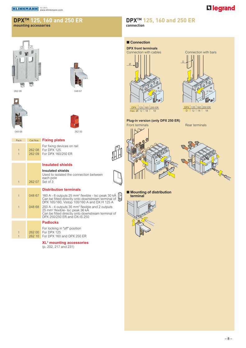
Connection
DPX front terminals
Connection with cables Connection with bars
6 Nm
Ø
Plug-in version (only DPX 250 ER)
Front terminals Rear terminals
6 Nm
D
Mounting of distribution terminal
DPX 125 160 250 ER
max. Ø 12 18 18
DPX 125 160 250 ER
D 12 18 18
XL3 mounting accessories (p. 202, 217 and 231)
www.klinkmann.com10 / 2011
– 8 –

DPXTM 250thermal magnetic and electronic release MCCBs from 40 to 250 A
253 49 253 52 254 23
Moulded case MCCBs for switching, control isolation and protection of low voltage electrical linesCan be fitted with auxiliaries (p. 86)Can be used with earth leakage modules (opposite) or with residual current relays (p. 87)Supplied complete with:- connection plates for bars- upstream and downstream connection devices for lugs (width max. 20 mm)- terminal shields Conform to IEC 60947-2Sealable adjustmentCan be mounted on plate in XL3 cabinets and enclosures
Dimensions (p. 91)Electrical characteristics (p. 94 - 103)
Pack Cat.Nos DPX 250 thermal magnetic
Thermal adjustable from 0.64 to 1 In Magnetic adjustable from 3.5 to 10 In
DPX 250 36 kA
Breaking capacity Icu 36 kA (400 V±) 3P 4P In
1 253 28 253 45 40 A
1 253 29 253 46 63 A
1 253 30 253 47 100 A
1 253 31 253 48 160 A
1 253 32 253 49 250 A
3P + N/2 In
1 253 41 160 A
1 253 42 250 A
DPX-H 250 70 kA
Breaking capacity Icu 70 kA (400 V±) 3P 4P In
1 253 52 253 69 40 A
1 253 53 253 70 63 A
1 253 54 253 71 100 A
1 253 55 253 72 160 A
1 253 56 253 73 250 A
3P + N/2 In
1 253 66 250 A
Im
Ir
t
I
Pack Cat.Nos DPX 250 electronic release S1
Adjustment of Ir and Im (p. 96) Instantaneous protection If = 4 kA Indicator lamp
Minimum current for indicator lamp operation (30 % of In) - green: normal - fixed red: I ≥ 0.9 Ir - flushing red: I ≥ 1.05 Ir Connector for test unit Dynamic selectivity 4P version: adjustment of neutral on front panel
DPX 250 36 kA
Breaking capacity Icu 36 kA (400 V±) 3P 4P In
1 254 01 254 07 40 A
1 254 03 254 09 100 A
1 254 04 254 10 160 A
1 254 05 254 11 250 A
DPX-H 250 70 kA
Breaking capacity Icu 70 kA (400 V±) In
1 254 13 254 19 40 A
1 254 15 254 21 100 A
1 254 16 254 22 160 A
1 254 17 254 23 250 A
Im If
Ir t
I
www.klinkmann.com10 / 2011
– 9 –

Red catalogue numbers : New products
DPXTM 250thermal magnetic and electronic release MCCBs from 40 to 250 A (continued)
260 55 260 53 265 32 265 46
Electronic earth leakage modules
Can be fitted onto DPX/DPX-I 250 Adjustable, sealable sensitivity:
0.03 - 0.3 - 1 - 3 A Adjustable, time delay: 0 - 0.3 - 1 - 3 s Test push-buttons
Reset push-button Remote earth fault signalling contact Switch for mechanical tests (installation insulation test)
Mounted underneath
Standard
3P 4P In
1 260 51 160 A
1 260 54 260 55 250 A
LED version
Monitors the isolation state of the installation via a series of LEDs
4P In
1 260 53 160 A
1 260 57 250 A
Draw-out version
A DPX draw-out version is a plug-in DPX fitted with a "Debro-lift" mechanism which can be used to withdraw the DPX while keeping it on its base
"Debro-lift" mechanism
Supplied with a rigid slide and handle for 3P 4P drawing-out
1 265 45 265 46 For DPX base only 1 265 47 For DPX base with earth leakage module
Key lock for "Debro-lift" mechanism
Enable locking of DPX in drawn-out position
1 265 76 1 key Ronis for DPX only 1 265 78 1 key Ronis for motorised DPX or with
rotary handle
Accessories for "Debro-lift" mechanism
1 265 75 Isolated handle for drawing-out 1 265 74 Signalling contact (plugged-in/drawn-out)
Supply invertor type
A supply invertor type is composed of one plate with interlock for 2 devices
1 264 08 Plate for MCCB or trip-free switch fixed version
1 264 03 Plate for MCCB or trip-free switch plug-in and draw-out version
Pack Cat.Nos Plug-in version
A plug-in is a DPX fitted with tulip contacts mounted on a base
3P 4P Tulip contacts
1 265 29 265 30 Set of tulip contacts (supplied with an incoming/outgoing protective cover)
Bases for DPX only
Accept DPX/DPX-I fitted with tulip contacts
1 265 31 265 32 Front terminal mounting base 1 265 33 265 34 Rear terminal mounting base with
threaded rod 1 265 35 265 36 Flat rear terminal mounting base
4P
Bases for DPX with earth leakage module
1 265 37 Front terminal mounting base 1 265 38 Rear terminal mounting base with
threaded rod 1 265 39 Flat rear terminal mounting base
Accessories
1 263 99 Set of connectors (8-pin) 1 098 19 Set of connectors (6-pin) 1 263 43 Set of 2 extractor handle
Pack Cat.Nos DPX 250 electronic release S2
Adjustment of Ir, Im, Tr, Tm (p. 96) Instantaneous protection If = 4 kA Indicator lamp
Minimum current for indicator lamp operation (30 % of In) - green: normal - fixed red: I ≥ 0.9 Ir - flushing red: I ≥ 1.05 Ir Connector for test unit Dynamic selectivity 4P version: adjustment of neutral on front panel
DPX 250 36 kA
Breaking capacity Icu 36 kA (400 V±) 3P 4P In
1 254 40 254 45 40 A
1 254 41 254 46 100 A
1 254 42 254 47 160 A
1 254 43 254 48 250 A
DPX-H 250 70 kA
Breaking capacity Icu 70 kA (400 V±) In
1 254 50 254 55 40 A
1 254 51 254 56 100 A
1 254 52 254 57 160 A
1 254 53 254 58 250 A
Im Tm
Tr
Ir t
I
www.klinkmann.com10 / 2011
– 10 –

DPXTM 250equipment and accessories
262 22 262 79 262 80 261 30
Motor-driven handles
Front operated
1 261 30 24 V±/= 1 261 34 230 V± Accessory
1 261 59 Ronis locking accessory
Pack Cat.Nos Rotary handles
Direct on DPX
1 262 22 Standard (grey) 1 262 24 For emergency use (red/yellow) - can be fitted on
Cat.Nos 262 22, 262 41 or 262 81
Vari-depth handle IP 55
Comprising: connection rod, bracket, self-adhesive drilling template, mounting accessories and door lock mechanism
1 262 79 Standard (black) 1 262 80 Conversion kit for emergency use
Can be fitted on Cat.No 262 79
Locking accessories
1 262 92 Eurolocks for vari-depth handle 1 262 93 Profalux for vari-depth handle 1 262 94 Ronis for vari-depth handle 1 262 25 Eurolocks for direct handle
Pack Cat.Nos Accessories
Insulated shields
1 262 30 Set of 3
3P 4P Sealable terminal shields
1 262 26 262 27 Set of 2 long terminal shields 1 262 28 262 29 Set of 2 short terminal shields
Padlock
1 262 21 For locking in "open" position
Cage terminals
1 262 35 Set of 4 terminals for cable 185 mm2 max. or 150 mm2 max. (flexible)
Adaptor for lug
For connecting bare cables with wide lug
1 262 31 Set of 1 adaptor + insulated shields
Extended front terminals
1 262 32 Set of 4
3P 4P Spreaders
1 262 33 262 34 Set of spreaders incoming or outgoing
Rear terminals
Used to convert the fixed version with front terminals to the fixed version with rear terminals
1 263 31 263 32 Set of rear terminals, incoming or outgoing
1 265 27 265 28 Set of flat rear terminals, incoming or outgoing
Distribution terminal 250 A
1 048 68 250 A - 4 outputs 35 mm2 flexible and 2 outputs 25 mm2 flexible - Isc peak 36 k Can be fitted directly onto downstream terminal of DPX 250/250 ER and DPX-IS 250
www.klinkmann.com10 / 2011
– 11 –

DPXTM 630thermal magnetic and electronic release MCCBs from 250 to 630 A
255 53255 40 256 07
Green indicator lamp (only S1): normal operation
minimum current for indicator lamp operation (30 % of In)
Fixed red indicator lamp: ≥ 0.9 Ir
Flushing red indicator lamp: I ≥ 1.05 Ir connector for test unit
Dimensions (p. 92)Electrical characteristics (p. 94 - 103)
Moulded case MCCBs for switching, control isolation and protection of low voltage electrical linesCan be fitted with auxiliaries (p. 86)Can be used with earth leakage modules or with residual current relays (p. 87)Supplied complete with:- connection plates for bars- terminal shieldsConform to IEC 60947-2 - Sealable adjustmentCan be mounted on plate in XL3 cabinets and enclosures
Pack Cat.Nos DPX 630 electronic release S1
Adjustment of Ir, Im, (p. 96) Instantaneous protection If = 5 kA
Green indicator lamp Connector for test unit Dynamic selectivity 4P version: adjustement of neutral on front panel
DPX 630 36 kA
Breaking capacity Icu 36 kA (400 V±) 3P 4P In
1 256 01 256 05 250 A
1 256 02 256 06 400 A
1 256 03 256 07 630 A
DPX-H 630 70 kA
Breaking capacity Icu 70 kA (400 V±) In
1 256 10 256 14 400 A
1 256 11 256 15 630 A
Pack Cat.Nos DPX 630 thermal magnetic
Thermal adjustable from 0.8 to 1 In Magnetic adjustable from 5 to 10 In
DPX 630 36 kA
Breaking capacity Icu 36 kA (400 V±) 3P 4P In
1 255 21 255 36 250 A
1 255 22 255 37 320 A
1 255 23 255 38 400 A
1 255 25 255 39 500 A
1 255 24 255 40 630 A
3P + N/2 In
1 255 32 320 A
1 255 33 400 A
1 255 35 500 A
1 255 34 630 A
DPX-H 630 70 kA
Breaking capacity Icu 70 kA (400 V±) 3P 4P In
1 255 42 255 57 320 A
1 255 43 255 58 400 A
1 255 45 255 59 500 A
1 255 44 255 60 630 A
3P + N/2 In
1 255 52 320 A
1 255 53 400 A
1 255 55 500 A
1 255 54 630 A
Im
Ir
t
I
Im If
Ir t
I
www.klinkmann.com10 / 2011
– 12 –

DPXTM 630thermal magnetic and electronic release MCCBs from 250 to 630 A (continued)
DPXTM 630
Pack Cat.Nos DPX 630 electronic release S2
Adjustment of Ir, Im, Tr, Tm (opposite) Instantaneous protection If = 5 kA Green indicator lamp Connector for test unit Logic and dynamic selectivity 4P version: adjustement of neutral on front panel
DPX 630 36 kA
Breaking capacity Icu 36 kA (400 V±) 3P 4P In
1 256 26 256 30 250 A 1 256 27 256 31 400 A 1 256 28 256 32 630 A
DPX-H 630 70 kA
Breaking capacity Icu 70 kA (400 V±) In
1 256 35 256 39 400 A 1 256 36 256 40 630 A
DPX-L 630 100 kA
Breaking capacity Icu 100 kA (400 V±) In
1 256 43 256 47 400 A 1 256 44 256 48 630 A
260 63256 35
Im Tm
Tr
Ir t
I
Earth leakage modules
Can be fitted onto DPX/DPX-I 630 Adjustable, sealable sensitivity:
0.03 - 0.3 - 1 - 3 A Adjustable, time delay: 0 - 0.3 - 1 - 3 s
Test push-button Reset push-button Remote earth fault signalling contact Switch for mechanical tests (installation insulation test)
Mounted underneath 230-500 V±
Standard
3P 4P In
1 260 60 260 61 400 A 1 260 64 260 65 630 A
LED version
Monitors the isolation state of the installation via a series of LEDs
4P In
1 260 63 400 A 1 260 67 630 A
If
Im
Ir t
I
based on the rms value of the current:Ir = 0.4 - 0.5 - 0.7 - 0.8 - 0.95 - 1 x In (8 steps)Tr = 5 s (fixed at 6 tr)
threshold:Im = 1.5 - 2 - 3 - 4 - 5 - 6 - 8 - 10 x Ir (8 steps)Tm = 0.05 s (fixed)
if with fixed threshold: If = 5 kA
S2 - Adjustment of Ir, Tr, Im, Tm
If
Im
Tm
Tr
Ir t
I
based on the rms value of the current:Ir = 0.4 - 0.5 - 0.7 - 0.8 - 0.9 - 0.95 - 1 x In (8 steps)Tr = 5 - 10 - 20 - 30 s (at 6 Ir) (4 steps)
threshold:Im = 1.5 - 2 - 3 - 4 - 5 - 6 - 8 - 10 x Ir (8 steps)Tm = 0 - 0.1 - 0.2 - 0.3 s (4 steps)Tm = 0.01 - 0.1 - 0.2 - 0.3 s at 12 x Ir (I2 t constant) (4 steps)
with fixed threshold: If = 5 kA
Performance data
S1 - Adjustment of Ir, Im
www.klinkmann.com10 / 2011
– 13 –

DPXTM 630equipment and accessories
265 57 265 67 262 51 262 48262 50
Pack Cat.Nos Plug-in version
A plug-in is a DPX fitted with tulip contacts mounted on a base
3P 4P Tulip contacts
1 265 50 265 51 Set of tulip contacts (supplied with an incoming/outgoing protective cover)
Bases for DPX only
Accept DPX/DPX-I fitted with tulip contacts 1 265 52 265 53 Front terminal mounting base 1 265 54 265 55 Rear terminal mounting base with
threaded rod 1 265 56 265 57 Flat rear terminal mounting base
4P Bases for DPX with earth leakage module
1 265 58 Front terminal mounting base 1 265 59 Rear terminal mounting base with
threaded rod 1 265 60 Flat rear terminal mounting base
Accessories
1 263 68 Set of 2 extractor handle 1 263 99 Set of connectors (8-pin)
Draw-out version
A DPX draw-out version is a plug-in DPX fitted with a "Debro-lift" mechanism which can be used to withdraw the DPX while keeping it on its base
"Debro-lift" mechanism
Supplied with a rigid slide and handle for 3P 4P drawing-out
1 265 66 265 67 For DPX base only 1 265 68 For DPX base with earth leakage module
Key-lock for "Debro-lift" mechanism
Enable locking of DPX in drawn-out position
1 265 76 1 key Ronis for DPX only 1 265 78 1 key Ronis for motorised DPX or with
rotary handle
Accessories for "Debro-lift" mechanism
1 265 75 Isolated handle for drawing-out 1 265 74 Signalling contact (plugged-in/drawn-out)
Pack Cat.Nos Rotary handles (continued)
Vari-depth handle IP 55
Comprising: connection rod, bracket, self-adhesive drilling template, mounting accessories and door lock mechanism
1 262 81 Standard (grey) 1 262 82 For emergency use (red/yellow) can be
fitted on Cat.Nos 262 81 or 262 41
Locking accessories
1 262 92 Eurolocks for vari-depth handle 1 262 93 Profalux for vari-depth handle 1 262 94 Ronis for vari-depth handle 1 262 25 Eurolocks for direct handle
Accessories
Insulated shields
1 262 30 Set of 3
3P 4P Sealable terminal shields
1 262 44 262 45 Set of 2
Padlock
1 262 40 For locking in "OPEN" position
Cage terminals
1 262 50 Set of 4 terminals for cable 300 mm2 max. (rigid) or 240 mm2 max. (flexible)
1 262 51 Set of 4 high-capacity terminals for cable 2 x 240 mm2 (rigid) or 2 x 185 mm2 (flexible)
Adaptor for lug
For connecting bare cables with wide lugs
1 262 46 Set of 4 adaptors + insulated shields
Extended front terminals
1 262 47 Set of 4
3P 4P Spreaders
1 262 48 262 49 Set of incoming or outgoing spreaders
Rear terminals
Used to convert the fixed version with front terminals to the fixed version with rear terminals
1 263 50 263 51 Set of incoming or outgoing swivel terminals
1 263 52 265 53 Set of incoming or outgoing flat terminals
Motor-driven handles
Front operated
1 261 40 24 V±/= 1 261 44 230 V± Accessory
1 261 59 Ronis locking accessory
Supply invertor type
Factory assembled A supply invertor type is composed of one
plate with interlock for 2 devices
1 264 09 Plate for MCCB or trip-free switch fixed version
1 264 04 Plate for MCCB or trip-free switch plug-in and draw-out version
Rotary handles
Direct on DPX
1 262 41 Standard (grey) 1 262 24 For emergency use (red/yellow) - can be
fitted on Cat.Nos 262 22, 262 41 or 262 81
www.klinkmann.com10 / 2011
– 14 –

DPXTM 1250 - 1600thermal magnetic and electronic release MCCBs from 800 to 1600 A
258 04 257 08
Pack Cat.Nos DPX 1250 thermal magnetic
Thermal adjustable from 0.8 to 1 In Magnetic adjustable from: 5 to 10 In
DPX 1250 50 kA
Breaking capacity Icu 50 kA (400 V±) 3P 4P In 1 258 02 258 09(1) 800 A 1 258 03 258 10(1) 1000 A 1 258 04 258 11(1) 1250 A
DPX-H 1250 70 kA
Breaking capacity Icu 70 kA (400 V±) In 1 258 16 258 23(1) 800 A 1 258 17 258 24(1) 1000 A 1 258 18 258 25(1) 1250 A
Dimensions (p. 93)Electrical characteristics (p. 94 - 103)
Moulded case MCBs for switching, control isolation and protection of low voltage electrical linesCan be fitted with auxiliaries (integrated terminal blocks)Can be used with earth leakage modules or with residual current relays (p. 87)Supplied complete with:- connection plates for bars- terminal shieldsConform to IEC 60947-2Fixed version - Sealable adjustment
(1) Neutral without protection (2) Neutral settings 0 - 0.5 - 1 N (0 - 50% - 100% Neutral)
Im
Ir
t
I
Pack Cat.Nos DPX 1600 electronic release S1
Adjustment of Ir, Im Instantaneous protection If = 20 kA Indicator lamp Minimum current for indicator lamp operation (30 % In): green: normal; fixed red: I ≥ 0.9 Ir; flashing red: I ≥ 1.05 Ir Connector for test unit Dynamic selectivity
DPX 1600 50 kA
Breaking capacity Icu 50 kA (400 V±) 3P 4P In 1 257 02 257 06(2) 800 A 1 257 03 257 07(2) 1250 A 1 257 04 257 08(2) 1600 A
DPX-H 1600 70 kA
Breaking capacity Icu 70 kA (400 V±) In 1 257 10 257 14(2) 800 A 1 257 11 257 15(2) 1250 A 1 257 12 257 16(2) 1600 A
DPX 1600 electronic release S2
Adjustment of Ir, Im, Tr, Tm Instantaneous protection If = 20 kA Indicator lamp Minimum current for indicator lamp operation (30 % In): green: normal; fixed red: I ≥ 0.9 Ir; flashing red: I ≥ 1.05 Ir Connector for test unit Logic and dynamic selectivity
DPX 1600 50 kA
Breaking capacity Icu 50 kA (400 V±) 3P 4P In 1 257 26 257 30(2) 800 A 1 257 27 257 31(2) 1250 A 1 257 28 257 32(2) 1600 A
DPX-H 1600 70 kA
Breaking capacity Icu 70 kA (400 V±) In 1 257 34 257 38(2) 800 A 1 257 35 257 39(2) 1250 A 1 257 36 257 40(2) 1600 A
Im Tm
Tr
Ir t
I
Im If
Ir t
I
www.klinkmann.com10 / 2011
– 15 –

Red catalogue numbers : New products
DPXTM 1250 - 1600equipment and accessories
265 84 (supplied assembled) 262 60 262 70 262 67 + 262 68
Pack Cat.Nos Draw-out version
A DPX draw-out version is a plug-in DPX fitted with a "Debro-lift" mechanism which can be used to withdraw the DPX while keeping it on its base
Draw-out base
Base for DPX 1600 supplied with "Debro-lift" assembled a rigid slide and 3P 4P handle for drawing-out
1 265 82 265 83 Front terminals 1 265 84 265 85 Rear terminals
Key lock for "Debro-lift" mechanism
Enable locking of DPX in drawn-out position
1 265 76 One key Ronis for DPX only 1 265 80 Two key Ronis (one key supplied) for
motorised DPX or with rotary handle
Accessories for "Debro-lift" mechanism
1 265 75 Isolated handle for drawing-out 1 265 74 Signalling contact (plugged-in/drawn-out)
Supply invertor type
A supply invertor type is composed of one plate with interlock for 2 devices
1 264 10 Plate for MCCBs or trip-free switch fixed version
1 264 05 Plate for MCCBs or trip-free switch plug-in and draw-out version
Rotary handles
Direct on DPX
1 262 61 Standard (black)
Vari-depth handle IP 55
Comprising: connection rod, bracket, self-adhesive drilling template, mounting accessories and door lock mechanism
1 262 83 Standard (black) 1 262 84 For emergency use (red/yellow)
Locking accessories
1 262 92 Eurolocks for vari-depth handle 1 262 93 Profalux for vari-depth handle 1 262 94 Ronis for vari-depth handle 1 262 25 Eurolocks for direct handle
Pack Cat.Nos Motor-driven handles
Factory assembled
Front operated
1 261 54 230 V± Customer assembled
Front operated
1 261 24 24 V±/= 1 261 25 48 V±/= 1 261 26 110 V±/= 1 261 23 230 V±/= for ratings up to 1250 A
(In ≤ 1250 A)
1 261 27 230 V±/= for 1600 A (In ≤ 1600 A)
Locking accessory
1 261 59 Ronis locking accessory
Accessories
Insulated shields
Used to isolate the connections between each pole
1 262 66 Set of 3
3P 4P Sealable terminal shields
1 262 64 262 65 Set of 2
Padlock
1 262 60 For locking in "open" position
Cage terminals
1 262 69 Set of 1 terminal for cables without lug 2 x 240 mm2 for rigid cable or 2 x 185 mm2 for flexible cable
1 262 70 Set of 1 high-capacity terminal for cables without lug 4 x 240 mm2 for rigid cable 4 x 185 mm2 for flexible cable
Extended front terminals
Set of 4
1 262 67 Short terminals for 630 - 1250 A (2 bars max. per pole)
1 262 68 Long terminals for 1600 A (3 bars max. per pole)
3P 4P Spreaders
1 262 73 262 74 Set of incoming or outgoing spreaders
Rear terminals
Used to convert the fixed version with front terminals to the fixed version with rear
terminals Set of incoming or outgoing rear terminals
1 263 80 263 82 Short terminals 1 263 81 263 83 Long terminals
www.klinkmann.com10 / 2011
– 16 –

DPXTM auxiliaries DPXTM auxiliaries
261 85
Pack Cat.Nos Auxiliary contact or fault signal
1 261 60 For signalling the state of the contacts or opening of the MCCB on a fault
For DPX/DPX-I/DPX-IS Changeover switch 3 A - 240 V±
Releases
Allow remote tripping of a DPX
Shunt releases
For DPX-IS/DPX-I and DPX Shunt inrush power 300 VA
1 261 64 Coil voltage 24 V±/= 1 261 65 Coil voltage 48 V±/= 1 261 66 Coil voltage 110 V±/= 1 261 67 Coil voltage 230 V±/= 1 261 68 Coil voltage 400 V±/=
For DPX/DPX-I 160
DPX/DPX-I 125 250ER, 630,
Undervoltage releases
DPX-IS 250, 1250, 1600 and For DPX-IS/DPX-I and DPX 630 DPX-IS 1600 Undervoltage power consumption 5 VA
1 261 70 261 80 Coil voltage 24 V= 1 261 71 261 81 Coil voltage 24 V± 1 261 72 261 82 Coil voltage 48 V= 1 261 76 261 86 Coil voltage 110 V± 1 261 73 261 83 Coil voltage 230 V± 1 261 74 261 84 Coil voltage 400 V± Time-lag (ms) undervoltage releases Allow remote tripping of a DPX
Prevent false tripping in the event of AC supply microbreaks Require a time-lag module connected to the undervoltage releases below
1 261 90 Time-lag modules 230 V± 3
1 261 91 Time-lag modules 400 V± 3
1 261 75 Undervoltage releases For DPX/DPX-I 125, DPX -IS 250,630
1 261 85 Undervoltage releases For DPX/DPX-I 160, 250ER, 630, 1250, 1600 and DPX -IS 1600
Number ofmodules
261 93
Automation control unit
For setting the conditions for supply inversion, generator on loft status acquisition for DMX and DPX circuit-breakers, open/closed Power supply: 230 V± and 12-24-48 V= Connection by plug-in terminals
1 261 93 Standard unit
1 261 94 Communicating unit, enabling data transmission (RS 485 port)
Auxiliary contact or fault signal
A singly Cat.No 261 60 auxiliary contact or fault signal
Undervoltage releases
Shunt releases
Time-lag undervoltage releases
AC = auxiliary contactEBAC = "early" auxiliary contactFS = break on trip contact
Max. number of contacts per DPX-IS device
Auxiliary contact Shunt release
Device AC EBAC FS or undervoltage release
Without DPX-IS 250 1 2 – –
release
With DPX-IS 250 1 1 1 1
release
Max. number of contacts per DPX device
Device
Auxiliary contact Shunt release
AC FS or undervoltage release
DPX 125 1 1 1
DPX 160 1 1 1
DPX 250 ER 1 1 1
DPX 250 2 1 1
DPX 630 2 2 1
DPX 1600 3 1 1
Electronic test unit
1 261 97 Test connector and software for connecting DPX to a PC Supplied with test software
www.klinkmann.com10 / 2011
– 17 –

Red catalogue numbers: New products
residual current relay and coilsresidual current relay and coils
260 88 260 93 coil for use with relay260 98
Add residual current protection to DPX trip-free switches and DPX MCCBs equipped with release
Pack Cat.Nos Residual current relay
Detects fault currents, and, when used with a shunt trip or an undervoltage release, it gives the trip command to a MCCB or a switch
- a tinged, sealable window - an auxiliary contact - a green Led indicating energisation - 3 yellow Leds indicating respectively the max. phase earth insulation current: 20, 40 and 60 % - a red Led indicating Fixed: exceeding of the insulation fault current value Flashing: breaking of one of the connections between coils and relays
- Ø35 and 80 mm Adjustable sensitivity: 0.03, 0.05, 0.075, 0.1, 0.15, 0.2, 0.3, 0.5, 0.75, 1, 1.5, 2, 3, 5, 7.5, 10, 15, 20, 30 A - Ø110 to 210 mm Adjustable sensitivity: 0.3, 0.5, 0.75, 1, 1.5, 2, 3, 5, 7.5, 10, 15, 20, 30 A - Ø150 mm Adjustable sensitivity: 0.5, 0.75, 1, 1.5, 2, 3, 5, 7.5, 10, 15, 20, 30 A - Ø300 mm Adjustable sensitivity: 1, 1.5, 2, 3, 5, 7.5, 10, 15, 20, 30 A
1 260 88 Residual current relay to clip on rail 2 2
Coils
For use with residual current relay Cat.No 260 88 1 coil per DPX
1 260 92 Coil Ø35 mm 1 260 93 Coil Ø80 mm 1 260 94 Coil Ø110 mm 1 260 95 Coil Ø140 mm 1 260 96 Coil Ø210 mm 1 260 97 Coil Ø150 mm - open 1 260 98 Coil Ø300 mm - open
Viking 3 disconnector block for measurement 1 connection
With its accessories, allows intervention (measurement, maintenance, etc) on a current, voltage and power measuring circuit by keeping the current transformer secondary circuit closed
Colour Nominal Capacity Pitch cross rigid Flexible (mm) section wire wire (mm2) (mm2) (mm2)
25 371 92 Grey 4 0.25 to 4 0.25 to 4 8
Number ofmodules
Residual current relay
Cat.No 260 88
60
35 446
35
45
90
88
Coils
Cat.Nos 260 92/93/94/95/96 Cat.No 260 97
6
22
LE
5.5
B
D
C
523 H M
A
B
A
M DL
C
3445
79E
H
Cat.No 260 98
310
368
400
30
58
57
21
Cat.Nos A B C D E H L M
260 92 35 75 85 42 92 36 43 56
260 93 80 108 132 67 125 36 65 56
260 94 110 148 170 86 165 36 84 56
260 95 140 177 206 104 200 36 102 56
260 96 210 270 295 150 290 44 145 64
260 97 150 225 259 133 245 275 95 113
www.klinkmann.com10 / 2011
– 18 –

DPXTM 125
Fixed version, front terminals with earth leakage module mounted side by side(1)
Dimensions
Fixed version, front terminals
Fixed version, rear terminals
Fixed version, front terminals with earth leakage module mounted underneath
Fixed version, rear terminals with earth leakage module mounted underneath
Rotary handle-direct on DPX
(1) Dimensions of 3-pole earth leakage modules are the same as 4-pole earth leakage modules(2) 70 mm without mechanical system
Rotary handle-vari-depth on door
Mounting with flexible seal
451
20
25.4
12
101
M4
97
74
32
8
8
101
37.8
45 101
120
25.4
1275.6
81
39
45
45 101
120
101
10
25.4
M8
M4
25.4
75.6 101 97
74 8
25.425.425.4
202
12.7
113.7
120
103
8
45
101
37.8 25.4
101
10
97
74
10
81
39
101
M8
21
0
45
19
1
32
.2545
25.425.4 25.4
74 8
97
M4
101
210
45
193
32.2
5
193
45
25.4
7410 8
9750.8
Ø 4.3 or M4
Terminal shields
A
8 74 48
6075.5
25.4
12.7
80
103
20
80
20
11.2
40.2
M4
70
7
103
M4
8 74
62.5
0.8/2 358.5 max.
173.5 min.(2)
A
DPX 125 170
DPX 125 + earth leakage module mounted underneath
260
www.klinkmann.com10 / 2011
– 19 –

DPXTM 160
Fixed version, front terminals with earth leakage module mounted side by side(1)
135
45
15
30
30
120
240
120
15
0
95
60
X
Y
Y
==
45
8748
97
86
13
2
M4
==
Dimensions
Fixed version, front terminals
Fixed version, rear terminals
48
95
15
0
45
90 120
30 30 30 30 30
97
74 8
Fixed version, rear terminals with earth leakage module mounted underneath
Rotary handle direct on DPX
(1) Dimensions of 3-pole earth leakage modules are the same as 4-pole earth leakage modules(2) 70 mm without mechanical system
Rotary handle-vari-depth on door
Mounting with flexible seal
Fixed version, front terminals with earth leakage module mounted underneath
120
30
26
5
14 30 30
45
45
45
24
7
978
9
23M4
74 8
15
01
15
Terminal shields
A
15
0
45
30
M4
23
90
97
238
74 8
18 max.
15
0
45
120
45
30
15
01
15
16
1
26
5
24
7
45
55
45
45
55
.524
1
15
8
97
7430 30
120
30
45
M10
8
95
48
8
M4
X
Y
80
30
75.5
15
35
1.5 max.
60
38.5
11.2
5
115
8 74 48M4
62.5
0.8/2
115
8 74 358.5 max.
141.5 min.(2)
M45 70
A
DPX 160 278
DPX 160 + earth leakage module mounted underneath
393
www.klinkmann.com10 / 2011
– 20 –

DPXTM 250 ER
Dimensions
Fixed version, front terminals
Fixed version, front terminals with earth leakage module mounted side by side(1)
250 A
160 A
45
53.5
115
145
176
38.5
69
270
30 30 30
30 30 30
30 30
30 30
30
20 max.
15150
215.5
Terminal shields
Fixed version with earth leakage module mounted underneath
Rotary handle-direct on DPX
Rotary handle-vari-depth on door
Mounting flexible seal
Front terminals Rear terminals
30 30
120
90
145
176
115
38.5
45
53.5
69
M4
10 m
ax.
30
8 18 Ømax.
18
30 30 30
45 74
97
18 11.5
1.6
20 max.
135
45
15
30
30
120240
120
176
95
60
X
Y
Y
==
115 76.5
M 4
A
97
7491.5
18
181.6
74
97
11.5
8 Ø18 max.120
30 30 30
30 30 30
4520 max.
237
67.8
52.8
62.7
45
M 4
10 m
ax.
10 m
ax.
45
83.3
267
298
107.7
74
97
11.5
62.7
45
M 4
8
45
62.5
0.8/2
115
8 74 358.5 max.
141.5 min.(2)
M45 70
80
30
75.5
15
35
1.5 max
60
38.5
11.2
5
115
8 74 48M4
(1) Dimensions of 3-pole earth leakage modules are the same as 4-pole earth leakage modules(2) 75 mm without mechanical system
A
DPX 250 ER 296
DPX 250 ER + earth leakage module
418
www.klinkmann.com10 / 2011
– 21 –

DPXTM 250
Dimensions
Fixed version, front terminals
Fixed version with earth leakage module mounted underneath(1)
Front terminals Rear terminals
Plug-in version, rear terminals
Draw-out version, rear terminals
Draw-out version, front terminals
Plug-in version, front terminals
Rotary handle-vari-depth on door
Mounting with flexible seal
Rotary handle-direct on DPX Terminal shields
(1) Dimensions of 3-pole earth leakage modules are the same as 4-pole earth leakage modules(2) 75 mm without mechanical system
A
200
94
170
10
25
35 35
35
11
17
138.5
105
364 min.
M5
27
100
105
173.5
140
70
17.5
35 35 35
52.5
140
24 52.5
100
94
308
35
70
17.5
M5
11 36
105
138.5
10
278
10
27
281.5
138.5
105 4 min.
105
35 35
173.5
173.5
942
00
100
35
140
35 35 35
52.5
186.5
153
4 min.
153
66.5
90
105 (3P)
140 (4P)
124.5
192.7
5
449.5
5 20 52.35
34
313
144.7
5
353.5
Ø9
Y
3535 35
X
187
32.5
34
45.534
34155
24.7
5
94
66.5
90
99.5
105
20
35 35
341.5
140 186.5
4 min.4
32.5
15335 35 35
94 245.5
200
90 66.5
33
Ø9
90
99.5
155
24.7
5
94
343445.5
187
108.7
5
173.5
66.5
47.5
47.5
93.5
93.5
35
M12 M12
35 35 35 35
Ø9
90
99.5
155
24.7
5
94
343445.5
187
108.7
5
173.5
66.5
81
37
10
35
19
35
26
Ø9
81
37
10
35
19
3535
26
62.5
18.5
132
105 0.8/2348 max.
131 min.(2)
25
94
100
50
5840
2.5 maxi.
A
DPX 250 330
DPX 250 + earth leakage module
438
www.klinkmann.com10 / 2011
– 22 –

DPXTM 630
Draw-out version, rear terminals
Rear terminal with threaded rod
A
DPX 630 390
DPX 630 + earth leakage
542
module
Plug-in version, front terminals
Plug-in version, rear terminals
Draw-out version, front terminals
183
260
220
32
94
94
15 m
ax.
15 m
ax.
M5
27
144
105 4 min.
501770
140
32 70
100 100
8743.5
43.5 43.543.543.5 43.5
183
32
94
70
100
21.75
412
372
87
43.543.5 43.5 27
Ø6 or
M5
17 50
105
144
4 min.
105 4 min.
372
144
398
302
220
94
140
32 29
100 100
43.5 43.5 43.5 43.5 43.5
183 153
192
70
4 min.
94
130
Ø14
X
153
X
192
4 min.
130
220
265
140 183
70
94
94
100 100
43.5 43.5 43.5
34
X
Y187
2934
45.5 34
5265
302
398
265
130
130 183
155
94
24.7
14
34
187
43.5 43.5 43.5
M 16
45.5 34
130
220
155
94
103
58
24.7
34
187
29
843.5 43.5
15
45.5 34
130
220
155
94
124
59
24.7
Flat rear terminal
Rotary handle-vari-depth handle on door
Mounting with flexible seal
Rotary handle-direct on DPX
Dimensions
Fixed version, front terminals
Fixed version with earth leakage module mounted underneath
Front terminals Rear terminals
62.5
18.5
132
105 0.8/2348 max.
131 min.(1)
47
94
100
505840
2.5 max.
A
(1) 75 mm without mechanical system
Terminal shields
www.klinkmann.com10 / 2011
– 23 –

DPXTM 1250 - DPXTM 1600
Fixed version, rear terminals
Rotary handle-direct on DPX Rotary handle-vari-depth handle on door
Mounting with flexible seal
Dimensions
Fixed version, front terminals
Draw-out version, rear terminals Terminal shields480
278 2
5 m
ax.
215
29
8
13 min.
M8
5 140
20
70
210
50
70
70
M10
25
100
M12
280
149
Y
XX
280
35
70 7070
140
320
169
94
298
158
Y
Y
280 (4P)
210 (3P)
100
94
105
169
320
X
Y
Y
90 40
1323
145.5
273
M8
118
13
32
14
68
238
2.5 max.
140
3
145.5
12
273
12.5
6
56
94
3
188
98
163
X
238
2.5 max.6
32
40
140
12.5
364
34.5325
299
256
325
360
253
218.5
70 70707070
125
62.5
125 66.5
67.5 49
2.5 max.
27
132
62.5
140 0.8/2359.5 max.
142.5 min.(1)
(1) 75 mm without mechanical system
Vertical Horizontal
www.klinkmann.com10 / 2011
– 24 –

DEVICES DPX 125 DPX 160 DPX 250 ER
Type of MCCB DPX-E DPX DPX DPX DPX DPX DPX DPX DPX 16 kA 25 kA 36 kA 25 kA 36 kA 50 kA 25 kA 36 kA 50 kA
Number of poles 1P 3P - 3P + N/2 - 4P 3P - 3P + N/2 - 4P 3P - 3P + N/2 - 4P
Nominal rating (A) 16 - 125 16 - 125 63 - 160 63 - 160 40 - 160 100 - 250
Breaking capacity (kA) (EN 60947-2 and IEC 60947-2)
400 V± - 16 25 36 25 36 50 25 36 50
230 V± 16 22 35 40 40 50 65 40 50 65
Breaking capacity Ics (% Icu) 50 100 50 75 100 75 50 100 75 50
Characteristics of use
Nominal frequency 50/60 Hz
Maximum rated operating voltage Ue (V) 230 V± 500 V± - 250 V= 500 V± - 250 V= 500 VV± - 250 V=
Category of use A A A
Thermal-magnetic adjustment
Thermal 0.7 to 1 In 0.64 to 1 In 0.64 to 1 In
Magnetic fixed fixed fixed
Electronic protection adjustment
S1
- - -
- - -
S2
- - -
- - -
Maximum cable cross-section
Rigid cable 70 mm2 95 mm2 185 mm2
Flexible cable 50 mm2 70 mm2 150 mm2
Copper bar and lug width 12 mm(1) 18 mm(1) 22 mm(1)
Tightening torque 6 Nm 10 Nm 10 Nm
Nominal current (In) at 40 °C (A)
In (A) 16 25 40 63 100 125 40 63 100 160 100 160 250
Phase 16 25 40 63 100 125 40 63 100 160 100 160 250
N 16 25 40 63 100 125 40 63 100 160 100 160 250
N/2 - - - - - 63 - - - 100 - - 160
Magnetic threshold (Im) (A)(2) Fixed
In (A) 16 25 40 63 100 125 40 63 100 160 100 160 250
Phase 480 625 800 950 1250 1250 400 630 1000 1600 1000 1600 2500
N 480 625 800 950 1250 1250 400 630 1000 1600 1000 1600 2500
N/2 950 1000 1600
DPXTM MCCBselectrical characteristics
(1) Copper bar only(2) Trip current for 50/60 Hz. For direct current, multiply by 1.5
www.klinkmann.com10 / 2011
– 25 –

DPX 250 DPX 250 DPX 630 DPX 630 DPX 1250 DPX 1600
Electronic trip Electronic trip Electronic trip
DPX DPX-H 50 kA 70 kA
Number of poles
Nominal rating (A)
Breaking capacity (kA)
400 V ±
230 V ±
Characteristics of use
Maximum rated
operating voltage Ue (V)
Category of use
Thermal-magnetic
adjustment
Thermal
Magnetic
Electronic protection
adjustment
S1
S2
Maximum cable
cross-section
Rigid cable
Flexible cable
Tightening torque
Nominal current
In (A)
Phase
N
N/2
In (A)
Phase
N
N/2
(1) Copper bar only(2) Trip current for 50/60 Hz. For direct current, multiply by 1.5
DEVICES
Type of MCCB
Breaking capacity Bre Ics (% Icu)
Magnetic threshold
Copper bar and lug width
3P - 4P
800 - 1600
(EN 60947-2 and IEC 60947-2)
50 70
80 100
100 75
Nominal frequency 50/60 Hz
690 V± - 250 V= 690 V± 690 VV± - 250 V= 690 V± 690 V± - 250 V= 690 V±
A A A A: In 630 A A B B: In 200 to 400 A
0.64 to 1 In - 0.8 to 1 In - 0.8 to 1 In -
3.5 to 10 In - 5 to 10 In -
5 to 10 In
-
- Ir: 0.4 to 1 In - Ir: 0.4 to 1 In - Ir: 0.4 to 1 In
- Im: 1.5 / 10 Ir - Im: 1.5 / 10 Ir - Im: 1.5 / 10 Ir
- Ir: 0.4 to 1 In - Ir: 0.4 to 1 In - Ir: 0.4 to 1 In Tr: 5 to 30 s Tr: 5 to 30 s Tr: 5 to 30 s
- Im: 1.5 / 10 Ir - Im: 1.5 / 10 Ir - Im: 1.5 / 10 In Tm: 0.01 to 0.3 s Tm: 0.01 to 0.3 s Tm: 0.01 to 0.3 s
185 mm2 185 mm2 300 mm2 or 2 x 240 mm2 300 mm2 or 2 x 240 mm2 2 or 4 x 240 mm2 2 or 4 x 240 mm2
150 mm2 150 mm2 240 mm2 or 2 x 185 mm2 240 mm2 or 2 x 185 mm2 2 or 4 x 185 mm2 2 or 4 x 185 mm2
25 mm 25 mm 32 mm 32 mm 50 mm 50 mm
15 Nm 15 Nm 15 Nm 15 Nm 20 Nm 20 Nm
40 63 100 160 250 40 100 160 250 250 320 400 500 630 250 400 630 800 1000 1250 800 1250 1600
40 63 100 160 250 40 100 160 250 250 320 400 500 630 250 400 630 800 1000 1250 800 1250 1600
40 63 100 160 250 0 - 50 - 100 % of phase value 320 400 500 630 0 - 50 - 100 % of phase value 800 1000 1250 0 - 50 - 100 % of phase value
40 63 63 100 160 250 250 250 320 500 500 630
Adjustable
63 100 160 250 250 400 630 800 1000 1250
220 - 350 - 560 - 900 - 1250 - 2000 - 3150 - 4000 - 5000 - 6250 -
630 1000 1600 2500 2500 4000 6300 8000 10000 12500
220 - 350 - 560 - 900 - 1250 - 2000 - 3150 - 4000 - 5000 - 6250 - 630 1000 1600 2500 2500 4000 6300 8000 10000 12500
220 - 220 - 350 - 560 - 800 - 1250 - 2000 - 630 630 1000 1600 1600 2500 4000
DPX 36 kA
DPX-H 70 kA
3P - 3P + N/2 - 4P
40 - 250
36 70
60 100
100 75
DPX 36 kA
DPX-H 70 kA
3P - 4P
40 - 250
36 70
60 100
100 75
DPX 36 kA
DPX-H 70 kA
3P - 4P
250 - 630 320 - 630
36 70
60 100
100 75
DPX 36 kA
DPX-H 70 kA
3P - 3P + N/2 - 4P
250 - 630 400 - 630
36 70
60 100
100 75
DPX 36 kA
DPX-H 70 kA
3P - 4P
800 - 1250
50 70
80 100
100 75
at 40 °C (A)
(Im) (A) (2)
www.klinkmann.com10 / 2011
– 26 –

DPXTM
reading DPX characteristic curves and adjustment ranges
I: actual currentIr: thermal protection against overloads (setting: Ir = x In)Im: magnetic protection against short-circuits (setting: Im = x In or Im = x Ir)As the abscissa of the curves represents the ratio I/Ir, modifying the setting of Ir will not change the graphical representation of the thermal trip. However, the magnetic setting can be read directly (between 3.5 and 10 in the example).
Tripping curve for a DPX thermal-magnetic trip
I: actual currentIr: long delay protection against overloads (setting: Ir = x In)Tr: long delay protection operation time (fixed value: 5 to 30 s)Im: short delay protection against short-circuits (setting: Im = x Ir, between 1.5 and 10 Ir in the example)Tm: short delay protection operation time (setting: 0 to 0.3 s)I2t constant (adjustable via Tm)If: fixed threshold instantaneous protection (4 to 20 kA depending on model)
Tripping curve for a DPX electronic release S2, adjustable Ir, Im, Tr and Tm
I: actual currentIr: long delay protection against overloads (setting: Ir = x In)Tr: long delay protection operation time (fixed value: 5 s at 6 Ir)Im: short delay protection against short-circuits (setting: Im = x Ir, between 1.5 and 10 Ir in the example)Tm: short delay protection operation time (fixed value: 0.1 s)If: fixed threshold instantaneous protection (4 to 20 kA depending on model)
Tripping curve for a DPX electronic release S1, adjustable Ir and Im
10 000
1 000
100
10
1
0.01
0.001
0.1
t (s)
1 32 4 5 10 20 30 50 100
Thermal realease zone
when cold
Thermal realease zone
when hot
Adjustable magnetic
realease zone
I/Ir
Im
I2t = K
Tr = 30 s 20 %
Tr = 20 s 20 %
Tr = 10 s 20 %
Tr = 5 s 20 %
1 32 4 5 100.2 10 10 10 20 3020 3020 304050
I/Ir
0.001
10 000
1 000
100
10
0.01
0.1
t (s)
1Im
Tm
Isf = 250 A Isf = 160 A
Isf = 100 A
Isf = 40 A
Isf = 630 A Isf = 1600 A Isf = 400 A Isf = 1250 A
Isf = 250 A Isf = 800 A
Isf = 160 A Isf = 630 A
I/In I/In I/In
10 20 30 40 50 701 32 4 56 100.2
I/In I/In I/InI/Ir
0.001
10 000
1 000
100
10Tr = 5 s
0.01
0.1
t (s)
1
Im
Isf = 250 A
Isf = 630 A
Isf = 400 A
Isf = 160 A
Isf = 250 A
Isf = 160 A
Isf = 100 A
Isf = 40 A
10 20 30 10 20
Isf = 1250 A
Isf = 800 A
Isf = 630 A
Isf = 1600 A
Adjustment for DPX electronic release
Setting DPX 250 / 630 / 1600 S1 DPX 250 / 630 / 1600 S2
Ir overload trip threshold (long delay)
0.4 - 0.5 - 0.6 - 0.7 - 0.8 - 0.9 - 0.95 - 1) x In
Tr long delay
trip timefixed: 5 s (to 6 Ir) 5 - 10 - 20 - 30 s (to 6 Ir)
Im short-circuit trip threshold (short delay)
(1.5 - 2 - 3 - 4 - 5 - 6 - 8 - 10) x Ir(1)
Tm Short delay
trip timefixed: 0.05 s 0 - 0.1 - 0.2 - 0.3 s
Adjustment for thermal-magnetic DPX
DPX 160
Setting
DPX 125 DPX 250 ER
DPX 250 DPX 630 DPX 1250
Ir overload trip threshold 0.7 to 1 In 0.64 to 1 In 0.64 to 1 In 0.8 to 1 In 0.8 to 1 In (thermal)
Im short-circuit fixed: 10 In trip threshold (100 and fixed: 10 In 3.5 to 10 In 5 to 10 In 5 to 10 In (magnetic) 125 rating)
(1) 7.9 Ir for DPX 630 In 630 A
www.klinkmann.com10 / 2011
– 27 –

selectivity table DPXTM / DPXTM thermal-magnetic
Limits of selectivity (three phase circuit at 400 V)
(1) Selectivity low
Upstream MCCB
DPX
DPX 125 (16 kA) DPX 160 (25 kA) DPX 250ER (25 kA) DPX 250 DPX 630 DPX 1250
DPX 125 (25 kA) DPX 160 (36 kA) DPX 250ER (36 kA) DPX-H 250 DPX-H 630 DPX-H 1250
Downstream MCCB DPX 125 (36 kA) DPX 160 (50 kA) DPX 250ER (50 kA)
In (A) 40 63 100 125 63 100 160 250 63 100 160 250 250 320 400 500 630 800 1000 1250
DPX Ist. (kA) 0.8 0.95 1.25 1.25 0.63 1 1.6 2.5 0.63 1 1.6 2.5 2.5 3.2 4 5 6.3 8 6 7.5
DPX 125 (16 kA)
16 0.8 1 1.2 1.2 0.63 1 1.6 2.5 0.63 1 1.6 2.5 6 6 6 6 8 T T T
25 0.8 1 1.2 1.2 1 1.6 2.5 1 1.6 2.5 6 6 6 6 8 T T T
40 1 1.2 1.2 1 1.6 2.5 1 1.6 2.5 6 6 6 6 8 T T T
63 1.2 1.2 1.6 2.5 1.6 2.5 6 6 6 6 8 T T T
100 1.6 2.5 1.6 2.5 4 4 4 6 8 T T T
125 1.6 2.5 1.6 2.5 4 4 4 6 8 T T T
DPX 125 (25 kA)
16 0.8 1 1.2 1.2 0.63 1 1.6 2.5 0.63 1 1.6 2.5 6 6 6 6 8 16 16 16
25 0.8 1 1.2 1.2 1 1.6 2.5 1 1.6 2.5 6 6 6 6 8 16 16 16
40 1 1.2 1.2 1 1.6 2.5 1 1.6 2.5 6 6 6 6 8 16 16 16
63 1.2 1.2 1.6 2.5 1.6 2.5 6 6 6 6 8 16 16 16
100 1.6 2.5 1.6 2.5 4 4 4 6 8 16 16 16
125 1.6 2.5 1.6 2.5 4 4 4 6 8 16 16 16
DPX 125 (36 kA)
16 0.8 1 1.2 1.2 0.63 1 1.6 2.5 0.63 1 1.6 2.5 6 6 6 6 8 16 16 16
25 0.8 1 1.2 1.2 1 1.6 2.5 1 1.6 2.5 6 6 6 6 8 16 16 16
40 1 1.2 1.2 1 1.6 2.5 1 1.6 2.5 6 6 6 6 8 16 16 16
63 1.2 1.2 1.6 2.5 1.6 2.5 6 6 6 6 8 16 16 16
100 1.6 2.5 1.6 2.5 4 4 4 6 8 16 16 16
125 1.6 2.5 1.6 2.5 4 4 4 6 8 16 16 16
DPX 160 DPX 250ER (25 kA)
63 1 1.6 2.5 1 1.6 2.5 2.5 3.2 4 5 6.3 16 16 16
100 1.6 2.5 1.6 2.5 2.5 3.2 4 5 6.3 16 16 16
160 2.5 2.5 2.5 3.2 4 5 6.3 16 16 16
250 3.2 4 5 6.3 16 16 16
DPX 160 DPX 250ER (36 kA)
63 1 1.6 2.5 1 1.6 2.5 2.5 3.2 4 5 6.3 16 16 16
100 1.6 2.5 1.6 2.5 2.5 3.2 4 5 6.3 16 16 16
160 2.5 2.5 2.5 3.2 4 5 6.3 16 16 16
250 3.2 4 5 6.3 16 16 16
DPX 160 DPX 250ER (50 kA)
40 0.63 1 1.6 2.5 0,63 1 1.6 2.5 2.5 3.2 4 5 6.3 16 16 16
63 1 1.6 2.5 1 1.6 2.5 2.5 3.2 4 5 6.3 16 16 16
100 1.6 2.5 1.6 2.5 2.5 3.2 4 5 6.3 16 16 16
160 2.5 2.5 2.5 3.2 4 5 6.3 16 16 16
250 3.2 4 5 6.3 16 16 16
DPX 250 (36 kA)
40 2.5 3.2 4 5 6.3 16 16 16
63 1 1.6 2.5 2.5 3.2 4 5 6.3 16 16 16
100 1.6 2.5 2.5 3.2 4 5 6.3 16 16 16
160 2.5 2.5 3.2 4 5 6.3 16 16 16
250 3.2 4 5 6.3 16 16 16
DPX 250 S1/S2 (36 kA)
40 3.2 4 5 6.3 16 16 16
100 3.2 4 5 6.3 16 16 16
160 3.2 4 5 6.3 16 16 16
250 3.2 4 5 6.3 16 16 16
DPX-H/L 250 (70/100 kA)
40 0,63 1 1.6 2.5 2.5 3.2 4 5 6.3 16 16 16
63 1 1.6 2.5 2.5 3.2 4 5 6.3 16 16 16
100 1.6 2.5 2.5 3.2 4 5 6.3 16 16 16
160 2.5 2.5 3.2 4 5 6.3 16 16 16
250 3.2 4 5 6.3 16 16 16
DPX-H/L 250 S1/S2 (70/100 kA)
40 3.2 4 5 6.3 16 16 16
100 3.2 4 5 6.3 16 16 16
160 3.2 4 5 6.3 16 16 16
250 3.2 4 5 6.3 16 16 16
DPX 630 (36 kA)
250 3.2 4 5 6.3 10 10 10
320 4 5 6.3 10 10 10
400 5 6.3 10 6 7.5
500 6.3 10 6 7.5
630 10 6 7.5
DPX-H/L 630 (70/100 kA)
250 3.2 4 5 6.3 10 10 10
320 4 5 6.3 10 10 10
400 5 6.3 10 6 7.5
500 6.3 10 6 7.5
630 10 6 7.5
DPX 630 S1/S2 (36 kA)(1)
250 6.3 8 6 8
400 6.3 8 6 8
630 8 6 8
DPX-H/L 630 S1/S2 (70/100 kA)(1)
400 6.3 8 6 8
630 8 6 8
DPX 1250 (50 kA)
800 7.5 7.5
1000 7.5
1250
DPX-H 1250 (70 kA)
800 7.5 7.5
1000 7.5
1250
www.klinkmann.com10 / 2011
– 28 –

selectivity table DPXTM / DPXTM electronic S1/S2
Limits of selectivity low (three-phase circuit at 400 V) Limits of selectivity high (three phase circuit at 400 V)
(1) Selectivity low
For S2 tripping unit possibility of logic selectivity (total selectivity)(1) Selectivity low
Upstream MCCB electronic SEL: LOW
DPXDPX 250 S1/S2 (36 kA) DPX 600 S1/S2 (36 kA) DPX/DPX-H 1600
S1 (50/70 kA)DPX/DPX-H 1600
S2 (50/70 kA)DPX/DPX-H 1600 S1,S2 (50/70 kA)Downstream MCCB DPX-H 250 S1/S2 (70 kA) DPX-H 630 S1/S2 (70 kA)
DPXIn (A) 40 100 160 250 250 400 630 800 800 1250 1600
Ist. (kA) 3.5 3.5 3.5 3.5 5 5 5 10 10 15 20
DPX 125 (16 kA)
16 3.5 3.5 3.5 3.5 8 8 8 T T T T
25 3.5 3.5 3.5 3.5 8 8 8 T T T T
40 3.5 3.5 3.5 6 6 6 T T T T
63 3.5 3.5 3.5 6 6 6 T T T T
100 3.5 3.5 6 6 6 T T T T
125 3.5 3.5 6 6 6 T T T T
DPX 125 (25 kA)
16 3.5 3.5 3.5 3.5 8 8 8 T T T T
25 3.5 3.5 3.5 3.5 8 8 8 T T T T
40 3.5 3.5 3.5 6 6 6 T T T T
63 3.5 3.5 3.5 6 6 6 T T T T
100 3.5 3.5 6 6 6 T T T T
125 3.5 3.5 6 6 6 T T T T
DPX 125 (36 kA)
16 3.5 3.5 3.5 3.5 8 8 8 25 T T T
25 3.5 3.5 3.5 3.5 8 8 8 25 T T T
40 3.5 3.5 3.5 6 6 6 25 T T T
63 3.5 3.5 3.5 6 6 6 25 T T T
100 3.5 3.5 6 6 6 25 T T T
125 3.5 3.5 6 6 6 25 T T T
DPX 160 DPX 250ER(25 kA)
63 3.5 3.5 3.5 6 6 6 20 T T T
100 3.5 3.5 6 6 6 20 T T T
160 3.5 6 6 6 20 T T T
250 6 6 20 T T T
DPX 160 DPX 250ER(36 kA)
63 3.5 3.5 3.5 6 6 6 20 T T T
100 3.5 3.5 6 6 6 20 T T T
160 3.5 6 6 6 20 T T T
250 3.5 3.5 6 6 20 T T T
DPX 160 DPX 250ER(50 kA)
40 3.5 3.5 3.5 8 8 8 20 T T T
63 3.5 3.5 3.5 6 6 6 20 T T T
100 3.5 3.5 6 6 6 20 T T T
160 3.5 6 6 6 20 T T T
250 6 6 20 T T T
DPX 250 (36 kA)
40 3.5 3.5 3.5 8 8 8 20 T T T
63 3.5 3.5 3.5 8 8 8 20 T T T
100 3.5 3.5 8 8 8 20 T T T
160 3.5 8 8 8 20 T T T
250 6 6 20 T T T
DPX 250 S1/S2 (36 kA)
40 1 1.6 2.5 8 8 8 20 T T T
100 1.6 2.5 6 8 8 20 T T T
160 2.5 6 8 8 20 T T T
250 6 6 20 T T T
DPX-H 250(70 kA)
40 3.5 3.5 3.5 8 8 8 20 30 30 36
63 3.5 3.5 3.5 8 8 8 20 30 30 36
100 3.5 3.5 8 8 8 20 30 30 36
160 3.5 8 8 8 20 30 30 36
250 6 6 20 30 30 36
DPX-H 250 S1/S2(70 kA)
40 1 1.6 2.5 8 8 8 20 30 30 36
100 1.6 2.5 6 6 6 20 30 30 36
160 2.5 6 6 6 20 30 30 36
250 6 6 20 30 30 36
DPX 630 (36 kA)
250 6 6 15 20 20 T
400 6 15 20 20 T
500 10 20 20 T
630 10 20 20 T
DPX-H 630(70 kA)
250 6 6 15 20 20 36
320 6 6 15 20 20 36
400 6 15 20 20 36
500 10 20 20 36
630 10 20 20 36
DPX 630 S1/S2 (36 kA)(1)
250 5 5 15 20 20 T
400 5 15 20 20 T
630 15 20 20 T
DPX-H 630 S1/S2 (70 kA)(1)
400 5 15 20 20 36
630 15 20 20 36
DPX 1250(50 kA)
800 20 20
1000 20 20
1250 20
DPX-H 1250(70 kA)
500 15 20 20 20
630 15 20 20 20
800 20 20
1000 20 20
1250 20
DPX/DPX-H 1600 S1(50/70 kA)(1) 800 15 20
DPX/DPX-H 1600 S2(50/70 kA)(1) 800 15 20
DPX/DPX-H 1600 S1/S2(50/70 kA)(1)
1250 20
1600
Upstream MCCB electronic SEL: HIGH
DPXDPX 250 S1/S2 (36 kA) DPX 630 S1/S2 (36 kA) DPX/DPX-H 1600
S1 (50/70 kA)DPX/DPX-H 1600
S2 (50/70 kA)DPX/DPX-H 1600 S1,S2 (50/70 kA)Downstream MCCB DPX-H 250 S1/S2 (70 kA) DPX-H 630 S1/S2 (70 kA)
DPXIn (A) 40 100 160 250 250 400 630 800 800 1250 1600
Ist. (kA) 3.5 3.5 3.5 3.5 5 5 5 10 10 15 20
DPX 125 (16 kA)
16 T T T T T T T T T T T
25 T T T T T T T T T T T
40 T T T T T T T T T T
63 T T T T T T T T T T
100 T T T T T T T T T
125 T T T T T T T T T
DPX 125 (25 kA)
16 T T T T T T T T T T T
25 T T T T T T T T T T T
40 T T T T T T T T T T
63 T T T T T T T T T T
100 T T T T T T T T T
125 T T T T T T T T T
DPX 125 (36 kA)
16 25 25 25 25 T T T T T T T
25 25 25 25 25 T T T T T T T
40 25 25 25 T T T T T T T
63 25 25 25 T T T T T T T
100 25 25 T T T T T T T
125 25 25 T T T T T T T
DPX 160 DPX 250ER(25 kA)
63 25 25 25 T T T T T T T
100 25 25 T T T T T T T
160 25 T T T T T T T
250 T T T T T T
DPX 160 DPX 250ER(36 kA)
63 25 25 25 T T T T T T T
100 25 25 T T T T T T T
160 25 T T T T T T T
250 T T T T T T
DPX 160 DPX 250ER(50 kA)
40 25 25 25 36 36 36 36 36 36 36
63 25 25 25 36 36 36 36 36 36 36
100 25 25 36 36 36 36 36 36 36
160 25 36 36 36 36 36 36 36
250 36 36 36 36 36 36
DPX 250 (36 kA)
40 36 36 36 T T T T T T T
63 36 36 36 T T T T T T T
100 36 36 T T T T T T T
160 36 T T T T T T T
250 T T T T T T
DPX 250 S1/S2 (36 kA)
40 T T T T T T T T T T
100 T T T T T T T T T
160 T T T T T T T T
250 T T T T T T
DPX-H 250(70 kA)
40 36 36 36 36 36 36 36 36 36 36
63 36 36 36 36 36 36 36 36 36 36
100 36 36 36 36 36 36 36 36 36
160 36 36 36 36 36 36 36 36
250 36 36 36 36 36 36
DPX-H 250 S1/S2(70 kA)
40 36 36 36 36 36 36 36
100 36 36 36 36 36 36 36
160 36 36 36 36 36 36 36
250 36 36 36 36 36 36
DPX 630 (36 kA)
250 T T T T
400 T T T T
500 T T T T
630 T T T T
DPX-H 630(70 kA)
250 25 25 36 36 36 36
320 25 25 36 36 36 36
400 25 36 36 36 36
500 25 36 36 36 36
630 36 36 36 36
DPX-H 630 S1/S2 (36 kA)(1)
250 T T(1) T(1) T(1)
400 T T(1) T(1) T(1)
630 T T(1) T(1) T(1)
DPX 630 S1/S2 (70 kA)(1)
400 25 36 36(1) 36(1) 36(1)
630 36 36(1) 36(1) 36(1)
DPX 1250(50 kA)
800 36 36
1000 36 36
1250 36
DPX-H 1250(70 kA)
500 36 36 36 36
630 36 36 36 36
800 36 36
1000 36 36
1250 36
DPX/DPX-H 1600 S1(50/70 kA)(1) 800 36 36
DPX/DPX-H 1600 S2(50/70 kA)(1) 800 36(1) 36(1)
DPX/DPX-H 1600 S1/S2(50/70 kA)(1)
1250 36(1)
1600
www.klinkmann.com10 / 2011
– 29 –

Upstream MCBs
DPX 125 (16 kA) DPX 160 (25 kA) DPX 250 ER (25 kA)DPX 250 (36 kA)
DPX-H 250 (70 kA)DPX 630 (36 kA)
DPX-H 630 (70 kA)DPX 1250/1600 (50 kA)
DPX-H 1250/1600 (70 kA)DPX 125 (25 kA) DPX 160 (36 kA) DPX 250 ER (36 kA)
DPX 125 (36 kA) DPX 160 (50 kA) DPX 250 ER (50 kA)
Downstream MCBs In 16 A 25 A 40 A 63 A 100 A 125 A 63 A 100 A 160 A 100 A 160 A 250 A 40 A 63 A 100 A 160 A 250 A 250 A 400 A 630 A 800 A 1000 A 1250 A
LR 6000
DX 6000 6 kA
DX 6000 10 kA
DX-H 10000 25 kA(1)
B and C curves
1 A T T T T T T T T T T T T T T T T T T T T T T T
2 A T T T T T T T T T T T T T T T T T T T T T T T
3 A T T T T T T T T T T T T T T T T T T T T T T T
4 A T T T T T T T T T T T T T T T T T T T T T T T
6 A 6000 6000 6000 6000 T T T T T T T T 6000 6000 T T T T T T T T T
10 A 5000 5000 5000 5000 7500 7500 7500 7000 T T T T 5000 5000 T T T T T T T T T
16 A 4000 4000 4000 6000 6000 6000 6000 T T T T 4000 4000 T T T T T T T T T
20 A 3000 3000 3000 5000 5000 5000 5000 T 8000 T T 4000 4000 8000 T T T T T T T T
25 A 3000 3000 4500 4000 4500 4500 8500 6000 8500 T 3000 3000 6000 T T T T T T T T
32 A 2000 4000 4000 4000 4000 7000 5000 7000 T 2000 5000 T T T T T T T T
40 A 2000 3000 3000 3000 3000 6000 4000 6000 T 5000 T T T T T T T T
50 A 3000 3000 3000 3000 5500 4000 5500 7000 4000 8000 T T T T T T T
63 A 3000 3000 3000 3000 5000 3000 5000 6000 4000 8000 T T T T T T T
80 A 2000 2000 2000 5000 2500 5000 6000 8000 T T T T T T T
100 A 4000 4000 5000 7500 T T T T T T T
125 A 2000 2000 3000 3000 8000 T T T T T T
DX-D 6000
1 A T T T T T T T T T T T T T T T T T T T T
2 A T T T T T T T T T T T T T T T T T T T T
3 A T T T T T T T T T T T T T T T T T T T T
6 A 6000 6000 T T T T T T T T 6000 T T T T T T T T T
10 A 5000 5000 7500 7500 7500 7500 T T T T 5000 T T T T T T T T T
16 A 4000 4000 6000 6000 6000 6000 T 6000 T T 4000 T T T T T T T T T
20 A 3000 3000 5000 5000 5000 5000 T 6000 T T 4000 8000 T T T T T T T T
25 A 3000 3000 4500 4500 4500 4500 8500 5500 8500 T 3000 6000 T T T T T T T T
32 A 2000 4000 4000 4000 4000 7000 4500 7000 T 2000 5000 T T T T T T T T
40 A 2000 3000 3000 3000 3000 6000 4500 6000 T 2000 5000 T T T T T T T T
50 A 3000 3000 3000 3000 5500 3500 5500 T 4000 8000 T T T T T T T
63 A 3000 3000 3000 3000 5000 3500 5000 6000 4000 8000 T T T T T T T
80 A 1500 4000 4000 5000 7000 T T T T T T T
100 A 3000 3000 4000 6500 T T T T T T T
125 A 1500 1500 2000 2000 7000 T T T T T T
DX-L 50 kA
C curve
10 A T T T T T T T T T T T T T T T T
16 A T T T T T T 40000 T T T T T T T T
20 A 20000 20000 T 22000 T T 33000 T T T T T T T T
25 A 15000 15000 T 18000 T T 28000 T T T T T T T T
32 A 10000 10000 20000 13000 T T 20000 T T T T T T T T
40 A 7000 7000 17000 8000 20000 20000 13000 T T T T T T T T
50 A 3000 3000 8000 4000 10000 20000 8000 20000 T T T T T T T
63 A 3000 3000 8000 4000 10000 15000 8000 20000 T T T T T T T
selectivity tablesxxxxxxMCCBs/MCBs
Upstream fuse
MCCBs
gG type
downstream 250 A 400 A 1000 A
DPX 125 7500
DPX 160 10000
DPX 250 ER 10000
DPX 250 10000
DPX 630 50000
T: total selectivity, up to downstream circuit breaker breaking capacity according to IEC 60947-2(1) For breaking capacity of DX-H MCBs, according to IEC 60947-2 (see p. 150)
www.klinkmann.com10 / 2011
– 30 –

MCBs/MCCBs upstream
DX-H 10000 - 25 kAB and C curves
DX-LDPX-E
125DPX 125
DPX/DPX-H 160
DPX 250 ER DPX/H/L 250DPX/H/L
630DPX/H/L 630
electronicDPX/H/L
1250DPX/H/L
1600
MCBs downstream 2 to 32 A 40 to 125 A 10 to 32 A 40 to 63 A 16 to 125 A 16 to 125 A 25 to 160 A 63 A 100 A 160 A 250 A 160 A 250 A 250 to 400 A 160 & 400 A 630 A500 to 1250 A
800 to 1600 A
DX 6000 - 10 kA
B and C curves
1 to 20 A 25(1) 12.5 50 25 16 25 25 25 25 25 25 25 25 25 25 25 25 25
25 A 25(1) 12.5 50 25 16 25 25 25 25 25 25 25 25 25 25 25 20 20
32 A 12.5 25 16 25 25 25 25 25 25 25 25 25 25 25 15 15
40 A 12.5 25 16 25 25 25 25 25 25 25 20 20 20 20 15 15
50 A 25 16 25 20 25 25 20 20 20 15 15 15 15 12.5 12.5
63 A 16 25 15 20 15 15 15 15 15 15 15 12.5 12.5
80 A 20 25 20 20 20 20 20 20 15
100 A 20 25 20 20 20 20 20 20 15
125 A 25 15 15 15 15 15 15 10
DX-H 10000 - 25 kA
B and C curves
DX 6000 - 15 kA
D curve
1 to 16 A 50 25 16 25 25 25 25 25 25 25 25 25 25 25 25 25
20 A 50 25 16 25 20 25 25 25 25 25 25 25 25 25 25 25
25 A 25 16 25 15 25 25 25 25 25 25 25 25 25 20 20
32 A 25 16 25 20 25 25 25 25 25 25 25 25 25 15 15
40 A 25 16 25 20 25 25 25 25 25 20 20 20 20 15 15
50 A 25 16 25 15 25 25 20 20 20 15 15 15 15 12.5 12.5
63 A 16 25 25 25 20 15 15 15 15 15 15 15 12.5 12.5
DX-L - 50 kA
C curve10 to 63 A 50 50 50 50 50 50 50 50 50 50 50 50 50 50
MCBs/MCCBs upstream
DX-H 10000 - 25 kAB and C curves
DX-LDPX-E
125DPX 125
DPX/DPX-H 160
DPX 250 ER DPX/H/L 250DPX/H/L 630
electronicDPX/H/L
1250DPX/H/L
1600
MCBs downstream 2 to 32 A 40 to 63 A 80 to 125 A 10 to 32 A 40 to 63 A 16 to 125 A 16 to 125 A 25 to 160 A 63 A 100 A 160 A 250 A 160 A 250 A 250 to 400 A 160 & 400 A 630 A500 to 1250 A
800 to 1600 A
DX 6000 - 10 kA
B and C curves
1 to 20 A 50 25 20 50 25 22 35 35 50 50 50 50 50 50 50 50 50 50 50
32 & 40 A 25 20 25 22 35 35 50 50 50 50 50 50 50 50 50 50 50
50 A 25 16 25 25 36 36 36 36 36 30 30 30 25 25 25
63 A 16 25 15 30 30 30 30 30 30 30 25 25 25
80 A 16 25 25 25 25 25 25 25 25 25 20
100 A 16 25 25 25 25 25 25 25 25 20
125 A 25 25 25 25 25 25 25 20
DX-H 10000 - 25 kA
B and C curves
DX 6000 - 15 kA
D curve
1 to 40 A 50 25 22 35 35 50 50 50 50 50 50 50 50 50 50 50
50 A 25 16 25 25 36 36 36 36 36 30 30 30 25 25 25
63 A 16 25 25 30 30 30 30 30 30 30 25 25 25
DX-L - 50 kA
C curve10 to 63 A 70 70 70 70 70 70 70 70 70 70 70 70 70
back up between MCCBs and MCBs (in kA)
TT or TN neutral earthing systems:For a 230/400 V supply in order to determine the breaking capacity of a 2 P MCB used as L + N (230 V) downstream a 2 P or 4 P circuit breaker use values indicated in the table for 230/240 V
In 3 phases networks + N 400/415 V according to IEC 60947-2
In 3 phases networks + N 230/240 V according to IEC 60947-2
In 3 phases networks (+ N) 400/415 V according to IEC 60947-2
In 3 phases networks (+ N) 230/240 V according to IEC 60947-2
Fuses upstream
gG type
MCBs downstream 20 to 32 A 63 to 160 A
1 A
to 100 100
DX 40 A
6000 - 10 kA
C and D curves 50 A
to 100
125 A
2 A
to 100 100
DX-H 40 A
10000 - 25 kA
B and C curves 50 A
to 100
63 A
10 A
to 100 100
40 A
DX-L - 50 kA
C curve 50 A
to 100
63 A
Fuses upstream
gG type
MCBs downstream 20 to 50 A 63 to 160 A
1 A
to 100 100
DX 40 A
6000 - 10 kA
C and D curves 50 A
to 100
125 A
2 A
to 100 100
DX-H 40 A
10000 - 25 kA
B and C curves 50 A
to 100
63 A
10 A
to 100 100
40 A
DX-L - 50 kA
C curve 50 A
to 100
63 A
(1) The breaking capacity value of DX-H 25 A and 32 A is 25 kA, only when DX-H MCB is backed-up by an upstream DX-L or DPX MCCB (3 back-up levels)In any other situation the breaking capacity values of DX-H are 20 kA for DX-H 25 A and 15 kA for DX-H 32 A (see p. 150)
www.klinkmann.com10 / 2011
– 31 –

Legrand_Protection_DPX-125-1600_en_0811.pdf
Samaratel. +7 846 273 95 [email protected]
Yekaterinburgtel. +7 343 376 [email protected]
St. Petersburgtel. +7 812 327 [email protected]
Moscowtel. +7 495 641 [email protected]
Helsinkitel. +358 9 540 [email protected]
Vilniustel. +370 5 215 [email protected]
Rigatel. +371 6738 [email protected]
Мinsktel. +375 17 200 [email protected]
Tallinntel. +372 668 [email protected]
Кievtel. +38 044 495 33 [email protected]
www.klinkmann.com
– 32 –


![MCCBs: DPX TM - Electroshops.roelectroshops.ro/blog/wp-content/uploads/2014/02/Disjunctoare-DPX-L... · TM] MCCBs: DPX TM The compact range of ... Type of MCCB E Ultimate breaking](https://img.pdfslide.us/doc/110x75/5adc8ef37f8b9ae1408bb720/mccbs-dpx-tm-mccbs-dpx-tm-the-compact-range-of-type-of-mccb-e-ultimate-breaking.jpg)