Embed Size (px)
Citation preview

© National Institute of Information and Communications Technology
New Generation Network New Generation Network Architecture Design Architecture Design andand Optical Optical Grid over Wavelength Switched Grid over Wavelength Switched Optical NetworkOptical Network
FuturICTFuturICT 20092009June 29, 2009June 29, 2009Hiroaki Harai (Hiroaki Harai ([email protected]@nict.go.jp))http://{http://{akariakari--project, project, nag}.nict.go.jpnag}.nict.go.jp//

2
Why New Generation Network?• Current & near-future situation
– The Internet has grown as the most important worldwide ICT infrastructure.– Telephone network will be renovated by NGN (Next Generation Network), of
which transport is constructed by IP network system.– NGN is expected to provide sophisticated solutions for solving the problems
in the Internet, e.g. QoS, Security, etc.• However, we have still many problems. For example:
– Large capacity of transmission/exchange (x103 by 2020 (1 Pbps))– Electric power consumption of core router (1 nuclear plant power
generation per 100 devices of 1Pbps electronic router)– Difficulty of guarantee of bandwidth (limit of packet switching system)– Difficulty of congestion control (bw-delay problem, fairness of users)– Difficulty of avoidance or fast recovery of break down (several tens
of seconds’ order needed for rerouting in wide areas)– Difficulty in introducing plural gateways, seamless mobility
(connection termination)– …
– Difficulty in building sustainable & evolvable network (patch??)
• New Generation Network (Vision, Net Design, Build)
Original Internet Architecture
hierarchal
addressinglocal addressingG
MPLS
flow-label
guaranteedservice?
universal communication?
small devices? authentication?
Adding Functions ??
dependability?
multicast
mobility
complicatedrouting
IPsecMPLS
anycast
NAT
© National Institute of Information and Communications Technology
AAKKARIARI Architecture Design Architecture Design Project Project (May 2006 - Present)
Designing the future, diverse, new generation network beyond 2015White paper of concept design is available from web
http://akari-project.nict.go.jp/http://www.akari-project.jp/

© National Institute of Information and Communications Technology 4
The primary mission of AKARI is to design a network architecture of the futureTo develop novel technologies for NWGN by 2015To envision a new infrastructure for the next two or three decadesTo pursue an ideal solution by researching new network architectures from a clean-slate without being impeded by existing constraints
AKARI Architecture Design PJ
2. Reality Connected• Physical-logical separation• Bi-directional authentication• Traceability
3. Sustainable & Evolutional• Self-* properties (emergent)• Autonomic distributed control• Openness
1. Crystal Synthesis (KIS*)• Selection, integration, simplification• Common layer (layer degeneracy)• Refined end-to-end
Social Potentiality PromotionReliable Network Space
Diversity Inclusion AKARI Sustainable Architecture Principles

5© National Institute of Information and Communications Technology
How to get to NWGN How to get to NWGN ““New Generation NetworkNew Generation Network”” ??
Present Network
RevisedNXGN
New GenerationNetwork (NWGN)
Vision, Design
2005 2010 2015
Past Network
Next GenerationNetwork (NXGN)
2) Incremental development with a future direction
1) Unconstraint design(Clean-slate approach)
AKARI … a small light in the dark pointing to the future
Max. the Potential
Min. the Negatives
Energy
Natural disaster
Medical
Food shortage
Anticrime
Accident
City- country gap
Aging society
Intl economic gap
Education
Cyber Security
Culture & life diversity
Media fusion
Knowledge society
Better productivity
new-value distribution
e-democracy
Entertainment
Frontiers

6© National Institute of Information and Communications Technology
Proof of
Concept
Concept &
Principles
Design
NW
GN
Blueprint
Innovation2006 2011 2016-
AKARI Design Project R&D PlanAKARI Design Project R&D PlanGrand-Designing a New Generation Network beyond 2015 -
(1) Design ideal network under clean-slate concept (2) Bridge current network and ideal network
Field Trial
Protocol
EngineeringTestbed
Construction
Testbed D
esign
JGN2plusNetwork Virtualization
JGN XPrototyping
StandardizationTestbed Design
Service & Operations
“AKARI Architecture Conceptual Design”See http://akari-project.nict.go.jp/eng/conceptdesign.htm
secured planned
7© National Institute of Information and Communications Technology
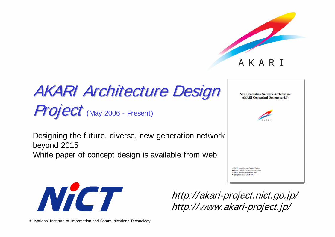
“Optical packet” & path integrationOptical accessWireless accessPDMATransport controlID-locator split internetworkingLayeringSecurityQoS routing
Enabling ComponentsEnabling Components in AKARI Architecturein AKARI ArchitectureUnder the design principlesUnder the design principles
Self-organizingRobustnessLayer degeneracySimplified IPOverlay networkNetwork virtualizationApplication platform
Optical Path NetWireless access
2. Reality Connected 3. Sustainable & Evolutional
1. Crystal Synthesis (KIS*)
Social Potentiality PromotionReliable Network Space
Diversity Inclusion

8© National Institute of Information and Communications Technology
Key Tech 1:Key Tech 1:
ID/locator Split Internetworking Architecture (1/2)ID/locator Split Internetworking Architecture (1/2)Objectives
Diversity inclusion through IDs and locators splitHandling network dynamismmore effectively
AdvantagesSupport heterogeneous network layer protocols
IP, post-IP, non-IPHelpful for mobility, multihoming, security, and routing functions
Design principleID/locator splitDiversity in networksReliable network space
Transport and upper layers
Mapping functions layer(ID LOCATOR)
Network layer
Use ID to identity host or session
Use LOCATOR to locate host in the network
ID/locator split protocol stack
Link and lower layers
Connection is terminated if IP addr is changed in the current Internet
Edge Networks
Global Transit Network
GWGW
HostsHosts

9© National Institute of Information and Communications Technology
ID/Locator Split Internetworking Architecture (2/2)ID/Locator Split Internetworking Architecture (2/2)Design and Development Overview
New naming and resolution systemUnified logical control network
Maintain and distribute hostname, ID, and locator mapping information securely, promptlyMaintain and distribute additional info for network management or control as well
Hash (global hostname, parameter)
Prefix | Scope | Version | Hash Value
ID prefix assignment
(e.g., myhost#mydomain.com)Global Hostname = Local Hostname # Domain Name
Host ID
Locator
New Naming System
Edge Networks
Global Transit Network
GWGW
Hosts
HNR HNR
Hosts
Unified Logical Control Network
Resolved by IDR
DNR
DNR
IDRIDR
Resolved by DNR & HNR
Update domain names, HNR ID&Locator
mapping
Update/retrieve Host ID&locator
mapping
Network LayoutOther servers
DNR: Domain Name Registry
HNR: Host Name Registry
IDR: ID Registry
[Domain Name HNR ID&Locator]
[Host Name Host ID&Locator]
[Host ID Host Locator]
Resolution System
10© National Institute of Information and Communications Technology
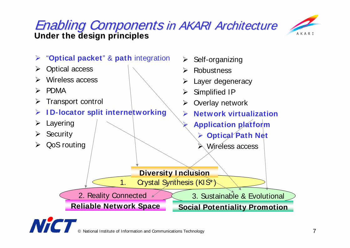
Key tech 2:Key tech 2:
Network VirtualizationNetwork Virtualization
Real TestBed Network
VN1 VN2 …
(a) Isolated Virtual Networks
Real Operational Network
VN1 VN2 …(b) Transitive Virtual Networks
Self-evolvable
Real Operational Network
VN1
VN2
(C) Overlaid Virtual Networks
Optical Path NetworkWireless Network

11© National Institute of Information and Communications Technology
Key tech 3:Key tech 3:
Optical Packet and Path Integration (1/2)Optical Packet and Path Integration (1/2)Objective
Providing diverse user requirements w/ large capacity
AdvantageHigh switching capacityLow power consumptionUsing common WDM infrastructureSimple control plane
Design principleCrystal synthesis (QoS)Sustainable (throughput, power, usage)
Best effort
Optical circuit switch
Optical packet switch
High-end, guaranteed quality
Wavelength sharing
Sensors, tagsHome
O/E/O
O/E/O O/O/O
O/E/O
O/O/OO/O/O
O/O/O
O/O/O
O/E/O
O/O/O
Ctrl info
Ctrl info or data
Packets Paths
Image view of optical integrated network
12© National Institute of Information and Communications Technology
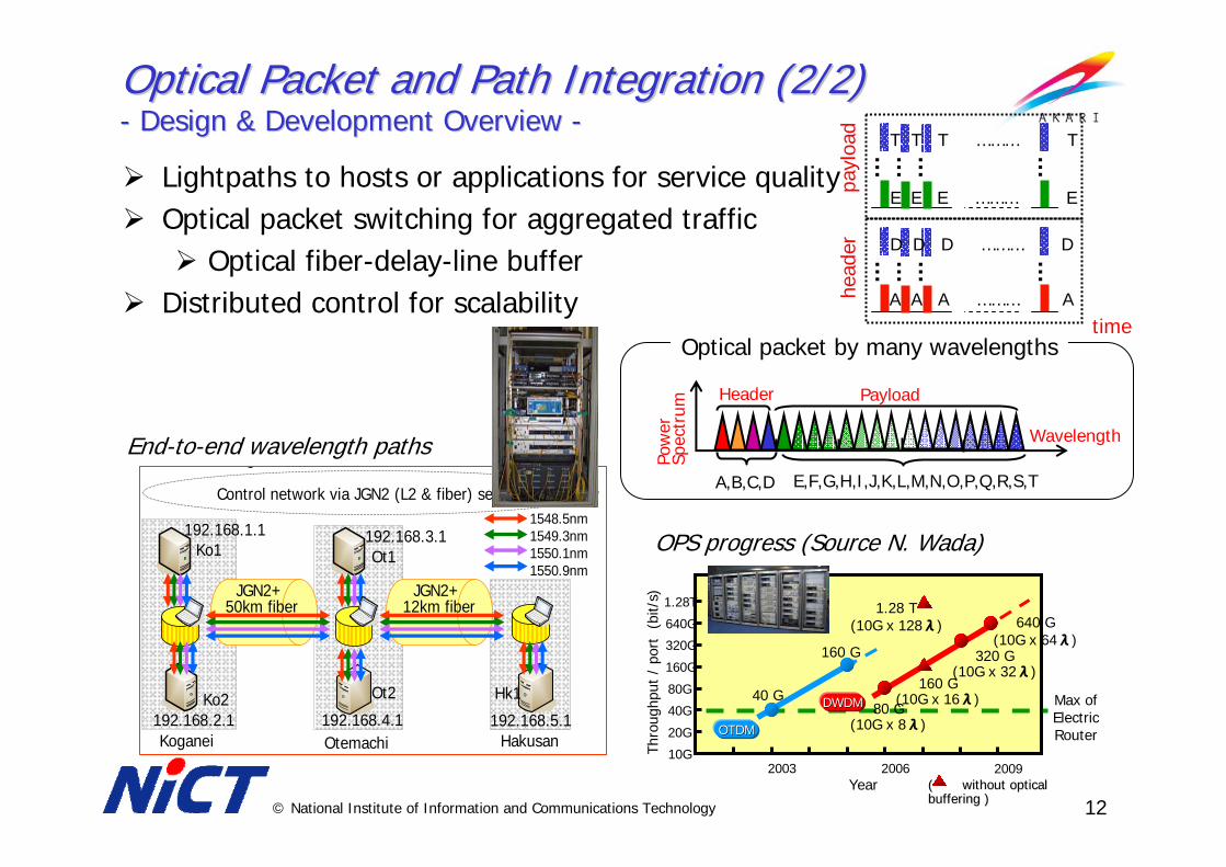
Optical Packet and Path Integration (2/2)Optical Packet and Path Integration (2/2)-- Design & Development Overview Design & Development Overview --
Lightpaths to hosts or applications for service qualityOptical packet switching for aggregated traffic
Optical fiber-delay-line bufferDistributed control for scalability
A,B,C,D E,F,G,H,I,J,K,L,M,N,O,P,Q,R,S,T
Wavelength
Pow
erSp
ectr
um
Header Payload
Optical packet by many wavelengths
20G
40G
80G
160GTh
roug
hput
/ p
ort
(bi
t/s)
320G
Year20062003
10G
640G
OOTDMTDM
1.28T
40 G
160 G
160 G(10G x 16λ)
1.28 T(10G x 128λ)
DDWDMWDM 80 G(10G x 8λ)
( without optical ( without optical buffering )buffering )
Max of Electric Router
2009
320 G(10G x 32λ)
640 G(10G x 64λ)
OPS progress (Source N. Wada)
Control network via JGN2 (L2 & fiber) service
JGN2+ 50km fiber
JGN2+ 12km fiber
Koganei Otemachi Hakusan
1548.5nm1549.3nm1550.1nm1550.9nm
g
192.168.2.1
192.168.1.1
192.168.4.1 192.168.5.1
192.168.3.1Ko1
Ko2
Ot1
Ot2 Hk1
End-to-end wavelength paths
head
erpa
yloa
d
E E E ……… E
T T T ……… T… … … …
timeA A A ……… A
D D D ……… D… … … …

13© National Institute of Information and Communications Technology Hiroaki Harai
Optical Grid over Wavelength Optical Grid over Wavelength Switched Optical NetworkSwitched Optical NetworkOne potential service over NWGN infrastructureOne potential service over NWGN infrastructure
14© National Institute of Information and Communications Technology Hiroaki Harai
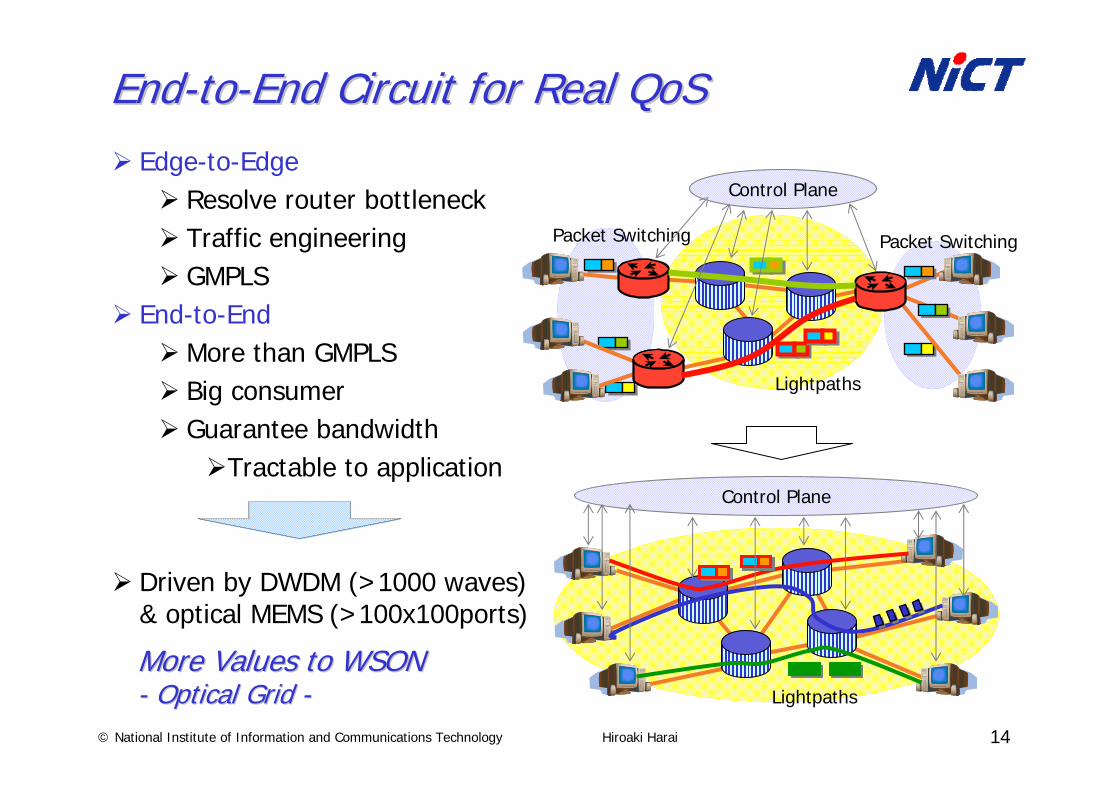
EndEnd--toto--End Circuit for Real End Circuit for Real QoSQoSEdge-to-Edge
Resolve router bottleneck Traffic engineeringGMPLS
End-to-EndMore than GMPLSBig consumerGuarantee bandwidth
Tractable to application
Driven by DWDM (>1000 waves) & optical MEMS (>100x100ports)
Packet Switching Packet Switching
Lightpaths
Control Plane
Lightpaths
Control Plane
More Values to WSONMore Values to WSON-- Optical Grid Optical Grid --
15© National Institute of Information and Communications Technology Hiroaki Harai
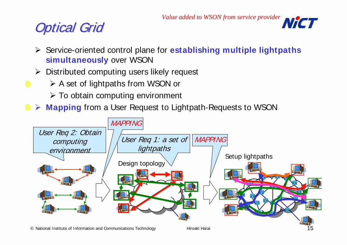
Optical Grid Optical Grid Service-oriented control plane for establishing multiple lightpaths simultaneously over WSONDistributed computing users likely request
A set of lightpaths from WSON orTo obtain computing environment
Mapping from a User Request to Lightpath-Requests to WSON
Design topologySetup lightpaths
User Req 1: a set of lightpaths
MAPPINGUser Req 2: Obtain
computing environment
Value added to WSON from service provider
MAPPING

16© National Institute of Information and Communications Technology Hiroaki Harai
Topology Design ServerTopology Design ServerSpecifies pairs of end hosts for lightpaths collecting Comp resource Info. & Net resource Info.A TD server in a host may design whole of topology or part of topology
TD servers in other hosts complete whole of topology via communicating token (TDCT)Topology design control tokenToken from a to b includes Info. of finishing setup of two lightpaths and delegation message to design remaining topology
Topology Design Control Token
a b dc
a
d c
a
d
b
c
a
d
b
c
a
d
b
c
Next step topology designNext step topology designNext step topology design
TDCTTDCT
TDCTTDCTTDCT copy
TDCTTDCTTDCT copy
TDCTTDCT

17© National Institute of Information and Communications Technology Hiroaki Harai
Built using JGN2plus optical fiber service
Implementation and ExperimentImplementation and Experiment
H. Harai et al., OFC 2009 (invited).
Control network via JGN2 (L2 & fiber) service
JGN2+ 50km fiber
JGN2+ 12km fiber
Koganei Otemachi Hakusan
1548.5nm1549.3nm1550.1nm1550.9nm
g
192.168.2.1
192.168.1.1
192.168.4.1 192.168.5.1
192.168.3.1Ko1
Ko2
Ot1
Ot2 Hk1
Lightpaths Established
Ko1
Ko2 Hk1
Ot2
2 hops
3 hops
3 hops
4 hops
3 hops
1548.5nm1549.3nm1550.1nm1550.9nm(a)
(b)
(c)
1549.3nm
1550.1nm 1550.9nm
Supervised signal
(c)
Experimental environment Dynamic network configuration and automatic IP addr, lambda allocation
User interface Wavelengths monitored
H. Harai et al., OFC 2009 (Invited)
18© National Institute of Information and Communications Technology Hiroaki Harai
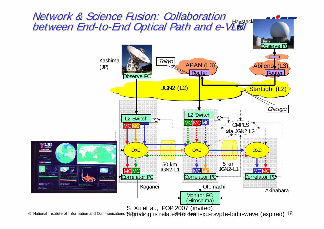
Network & Science Fusion: Collaboration Network & Science Fusion: Collaboration between Endbetween End--toto--End Optical Path and eEnd Optical Path and e--VLBIVLBI
APAN (L3)
L2 SwitchMCMC MC
MCMCCorrelator PC
MC MC
MCMC MCMC
OXC OXC OXC
GMPLSvia JGN2 L2
L2 Switch
Kashima(JP)
Correlator PC Correlator PC
50 kmJGN2-L1
Koganei OtemachiAkihabara
JGN2 (L2)
PCPC
Monitor PC (Hiroshima)
5 kmJGN2-L1
Abilene (L3)
Observe PC
Haystack (US)
Observe PC
StarLight (L2)
Chicago
Router Router
Tokyo
S. Xu et al., iPOP 2007 (invited). Signaling is related to draft-xu-rsvpte-bidir-wave (expired)
19
Summary• Towards New Generation Networks• AKARI Architecture
– Designing a network of future– Clean slate design and migration path from current to ideal net– Design principles + enabling techs R&D (Optical Packet & Path
Net, ID/Loc Split Net, Net virtualization, Self-organizing Ctrl. …)• Design and development of optical grid over WSON
– Providing end-to-end real QoS– Providing multiple lightpaths to a user simultaneously– Distributed control for provisioning multiple lightpaths– Experiment of the implemented system via JGN2plus fibers
Thank you for your attentionThank you for your attention
Acknowledgement: AKARI-PJ member for discussion about AKARI-PJ’s NWGN design


![Distributed Resources for the Earth System Grid Advanced ... · next-generation ESGF (Earth System Grid Federation [1]) architecture which would be suitable for managing and accessing](https://img.pdfslide.us/doc/110x75/5f337226a86df877e660c7b7/distributed-resources-for-the-earth-system-grid-advanced-next-generation-esgf.jpg)