Embed Size (px)
Citation preview
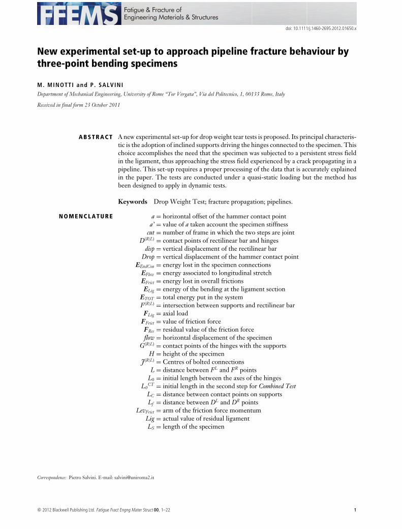
doi: 10.1111/j.1460-2695.2012.01650.x
New experimental set-up to approach pipeline fracture behaviour bythree-point bending specimens
M. MINOTTI and P. SALVINIDepartment of Mechanical Engineering, University of Rome “Tor Vergata”, Via del Politecnico, 1, 00133 Rome, Italy
Received in final form 23 October 2011
A B S T R A C T A new experimental set-up for drop weight tear tests is proposed. Its principal characteris-tic is the adoption of inclined supports driving the hinges connected to the specimen. Thischoice accomplishes the need that the specimen was subjected to a persistent stress fieldin the ligament, thus approaching the stress field experienced by a crack propagating in apipeline. This set-up requires a proper processing of the data that is accurately explainedin the paper. The tests are conducted under a quasi-static loading but the method hasbeen designed to apply in dynamic tests.
Keywords Drop Weight Test; fracture propagation; pipelines.
N O M E N C L A T U R E a = horizontal offset of the hammer contact pointa’ = value of a taken account the specimen stiffness
cut = number of frame in which the two steps are jointD(R|L) = contact points of rectilinear bar and hinges
disp = vertical displacement of the rectilinear barDrop = vertical displacement of the hammer contact point
EEndCon = energy lost in the specimen connectionsEFlow = energy associated to longitudinal stretchEFrict = energy lost in overall frictionsELig = energy of the bending at the ligament section
ETOT = total energy put in the systemF(R|L) = intersection between supports and rectilinear barFLig = axial load
FFrict = value of friction forceFRes = residual value of the friction forceflow = horizontal displacement of the specimen
G(R|L) = contact points of the hinges with the supportsH = height of the specimen
J(R|L) = Centres of bolted connectionsL = distance between FL and FR points
L0 = initial length between the axes of the hingesL0
CT = initial length in the second step for Combined TestLC = distance between contact points on supportsLf = distance between DL and DR points
LevFrict = arm of the friction force momentumLig = actual value of residual ligamentLS = length of the specimen
Correspondence: Pietro Salvini. E-mail: [email protected]
c© 2012 Blackwell Publishing Ltd. Fatigue Fract Engng Mater Struct 00, 1–22 1
2 M. MINOTT I AND P. SALV IN I
M(R|L) = mobile markers applied on the specimenMEndCon = average bending momentum at the connections
MLig = bending momentum at the centre of specimenmrect = the slope of the generic rectilinear lineMRes = residual value of the bending moment
O(R|L) = centres of the hingesof = offset of rectilinear barP = value of the hammer loadQ = middle point of the residual ligament
qrect = the y-intercept of the generic rectilinear liner = radius of support hinges
R(R|L) = frictionless reaction loadsRx,y = coordinates of the centroid of the hammer marker
Shiftx,y,θ= values of shifts for Combined Test procedureTx,y = coordinates of the crack tipW = intersection between the lines of the reaction loads
xi,yi = coordinates of the generic point iα = angle of the inclined supportsγ = horizontal attitude of the rectilinear bar
�(R|L) = rotation of the specimen halves at the connectionsδ = relative rotation of the two specimen halves
δin = last value of δ in the first step for Combined Test�x,y
(R|L) = differential coordinates of marker centroidsϑ = complementary angle of the support slopes
θ0(R|L) = initial inclinations of the specimen markers
θ (R|L) = actual inclinations of the specimen markersλ = inclination of bisector of the halves opening angle
I N T R O D U C T I O N
In the last 40 years, a considerable rise in the me-chanical characteristics of pipelines has been reached.Both pipeline diameters and operating pressures have in-creased, with the aim to improve the overall mass flowrate. 1
New generations of pipelines followed one another, sothat ductile steels could reach hoop stress limits evenabove 600 MPa.2 In the typical used scale of strength,the evolution began from the X52 API up to the recentX100 or X120. However, up to now, the new installationsof pipelines foresee the extensive use of X80 that is con-sidered mature enough to satisfy all safety and economicrequirements.
Ductile fracture resistance of pipelines is an importantissue to ensure that any possible catastrophic event mightbe confined to a delimited area. To this goal, a consider-able number of full-scale burst tests have been performedall over the world;3 all test results concern the capabilityto arrest the running of a longitudinal crack within thetested pipeline.
The key aspect is the correlation between the experimen-tal tests conducted in a laboratory context and the resultsof full-scale burst tests. Fracture behaviour of pipelines
is usually detected by Charpy V-notch (CVN) tests orby dynamic three point bending tests (DWTT). In thispaper, the attention is mainly focussed on DWTT thatseems more reliable for high-grade steels.
Improving the correlation involves a better effectivenessof the design criteria, necessarily based on laboratory tests.
A first important difference between laboratory tests andpipelines comes out from the nominal stress. The nom-inal value in a pipeline differs from the nominal stressapplied on the DWTT laboratory specimens. A secondaspect regards the longitudinal stretching of the pipe ina burst test that demonstrates the presence of a consis-tent longitudinal loading during crack propagation. As amatter of fact,4 the profile of the broken pipe presentsa consistent number of folds, documenting an increasedlength of the opening surfaces. Therefore, the pipe expe-riences, close to crack tip, a two-dimensional stress fieldwhile the DWTT laboratory specimens are affected onlyby bending, which involves a monodimensional stress.
This correlation was well fulfilled if applied to the lowerAPI-grade pipes. The developed models make use of abalancing between the driving and the resistance force,5
available during a crack growth. The driving forces aregiven by the work performed by gas pressure on theopening flanks; this energy is linked to the chemical
c© 2012 Blackwell Publishing Ltd. Fatigue Fract Engng Mater Struct 00, 1–22

NEW EXPERIMENTAL SET-UP TO APPROACH PIPEL INE FRACTURE 3
composition of the gas itself as well as to its thermo-dynamic conditions. The resistance force is the resultof several phenomena such as material ductility, inter-action with the soil surrounding the buried pipeline, in-ertial loads and so on. The method assumes that the twobalancing forces are independent each other, except forcrack speed. The intersection between the two drive andresistance forces points out the existence of a ductile stablepropagating speed.
The resistance curve is found by means of CVN mea-surements, which are elected to be representative ofthe ductile behaviour during fracture propagation. Themethod is appropriately tuned for low-grade pipelines.However, poorer results are obtained on high-strengthpipelines, even if some correcting factors were a posterioriintroduced.6
A different approach has therefore been suggested.7
It exploits the results given by an instrumented DropWeight Tear Test. These tests are conducted on a flat-tened specimen that is taken from the pipe in full thick-ness. Among all the possible approaches based on theenergy measurement during the crack propagation, thoseformulated on Crack Tip Opening Angle (CTOA) eval-uation seem very promising; they are more and more ac-cepted as arrest/propagation indicator for gas pipelines.8
Their typical framework is the assessment of a stable run-ning condition. Nevertheless, recent results demonstratedtheir validity in the computation of non-stationary crackpropagations, until crack arrest detection.9 The CTOAapproach, with some adjustments through the introduc-tion of the Work of Fracture,10 is able to manage non-stationary propagation phenomena, such as the crossing ofcrack stoppers or any longitudinal change in the pipelinegeometry or in the burying conditions.11
However, in the case of high-grade pipelines, the frac-ture criterion based on CTOA shows some discrepancieswith the burst test results, and some careful considerationsshould be carried out. As a matter of fact, the fracturemechanism considered could not reflect the real situationexperienced by the steel when the fracture grows.
Several specimen geometries, different from SEN-B,have been proposed for a more reliable application ofthe CTOA criterion. Among them: conventional com-pact tension specimens C(T) and middle tension speci-mens M(T),12 Three-Point Bending specimens 3-PB 13 ormultiple constrained specimens – able to include a largeramount of the plastic region ahead the crack tip.14,15
In this paper, possible causes of discrepancy are firstdiscussed and then an innovative experimental lay-out isproposed. This lay-out is applied on DWT Tests, so thatthe fracture mechanism was closer to the one experiencedby the pipe while a longitudinal fracture is running.
The method is applied on quasi-static tests performedon an instrumented tensile test device. Image process-
ing of subsequent frames of the test area allows theevaluations of the parameters required. The attention isprimarily focussed on the test layout and on experimentaldata manipulation, in spite to get information concerningcrack behaviour. Unlike the classical DWTT layout, herethe specimen is forced to slide on sloped supports, whoseangles can be appropriately selected.
A P P L I C A T I O N O F C R I T I C A L C T O A O NP I P E L I N E S
There are many reasons that make the fracture develop-ment in a pipeline different from the fracture advance-ment in a DWT Test. Average crack speeds are obviouslyvery different; furthermore, the regions where the cracktips develop are interested by non-matching stress andstrain fields.
The plastic zone ahead the crack tip in pipelines cangenerally extend even more than a diameter, especiallyin the longitudinal direction. The nominal stress filed isremarkably two-dimensional in pipelines, while bendingin DWTT produces only a one-dimensional stress field.Therefore, fracture development inside thickness (surfacetunnelling) can be different.16 The local necking that re-duces thickness may be not the same. Finally, the plasticcompression induced by the hammer can affect the frac-ture propagation results acquired in a DWT Tests.
Considering the effects that the constraint gives to frac-ture mechanics, some solutions have been presented.17
However, no proposals were suggested to modify theDWT Tests so that the stress field matches the one ex-perienced by pipelines, during crack running.
With the aim to gain a nominal stress field closer tothe pipeline one, a new layout to perform laboratory testson three point bending specimens is proposed. The mainadvantage of this new experimental set-up concerns thestress field ahead the crack tip, which now results froma bending associated with a consistent normal stress. Ina DWT Test, the stress ahead the tip decreases rapidly,since the nominal stress field is enforced by pure bending.Otherwise, on cracked pipelines, the nominal circumfer-ential stress is kept on by gas pressure. Moreover, theextension of the plastic region is obviously much widerthan SENB specimen. In SENB specimens, the plasticitycan reach the upper edge of the specimen only consid-ering the local compression induced by the action of thehammer; this is to say that tensional plasticity extensionis even lower than the thickness itself. This limited ex-tension can play a misleading role when considering theeffect of crack tunnelling.
The actual specimen thickness determines a constraineffect in the crack region, that induces a three-axial stressfield close to the tip. The amount of the reduction of
c© 2012 Blackwell Publishing Ltd. Fatigue Fract Engng Mater Struct 00, 1–22
4 M. MINOTT I AND P. SALV IN I
thickness should be similar in SENB and in the pipeline,but the effective constraint applied is also governed by thestress field consistency ahead the tip.
The new layout proposed here for DWT Tests is notable to reproduce the two-dimensional nominal state ofstress. However, it induces a state of stress ahead the cracktip characterized by its persistency. The distribution of theinternal energy extends so that it encompasses the wholefracture process zone (FPZ). As a matter of fact, one ofthe limits of the DWTT is that the energy decreases in-side the FPZ increasing the difficulties in the applicationof fracture mechanics criteria. Because the length of FPZis higher for more ductile materials this drawback is em-phasized for the new generations of pipeline steels.
Moreover, it is mandatory – to achieve reliable valuesfor fracture parameters such as CTOA, CTOD, etc.18
– to reach stable fracture growth. This stable fracturepropagation is not easy in principle to accomplish withthe DWTT layout. Without any doubt it is easier tomove towards a stable growth if the nominal stress aheadthe tip is consistent, as in the proposed layout. It is de-sirable that the critical values of the fracture parameters,identified by the proposed setup, were closer to the valuesto account during a fracture running in a pipeline. Thiscan be particularly true when dealing with the new high-grade steels that exhibit noteworthy plastic deformationsbefore rupture.
G E N E R A L D E S C R I P T I O N O F T H EE X P E R I M E N T A L S E T - U P
The typical set-up of an experimental DWTT providesthe measurement of the hammer load versus displace-ment. In such a way, the energy dissipation can be calcu-lated through simple manipulation and time integrationof the data.
DWT Tests were initially employed to gain informa-tion regarding the temperature of brittle/ductile transi-tion. When limited to this aim, the test does not need tobe instrumented since the result is obtained through theinspection of fracture aspect after test.
If the test is conducted with the help of an instrumentedhammer, it is possible to compute the Crack Tip Open-ing Angle of the fracture during a quasi-stable propaga-tion.19,20
The instrumentation here applied is also providedby a digital image recorder that automatically detectsthe positions of some markers, appropriately appliedon the system components. The exhaustive description ofthe digital system of acquisition is given in Refs. [16,21].Here, we discuss the whole procedure to gain the kinemat-ical movements of the mechanical components, exploitingthe identified locations of the markers, see Figs 1 and 2.
The description of the test is provided through the com-putation of a sequence of digital images taken during theadvancing of the hammer. The motion of the two spec-imen’s halves is identified during loading, even if otherdisplacements are acting in the assembly. The plastic de-formations of the specimen are concentrated on the lig-ament, while all other regions almost behave like rigidbodies. An exception is given by the connections of theextensions to the specimen (bolted joints), but their rela-tive displacements, as it will be clear later on, are properlyaccounted in the data manipulation.
Within all pictures, every marker is localized and thetaken attitudes (inclination by respect to horizontal plane)are also computed.
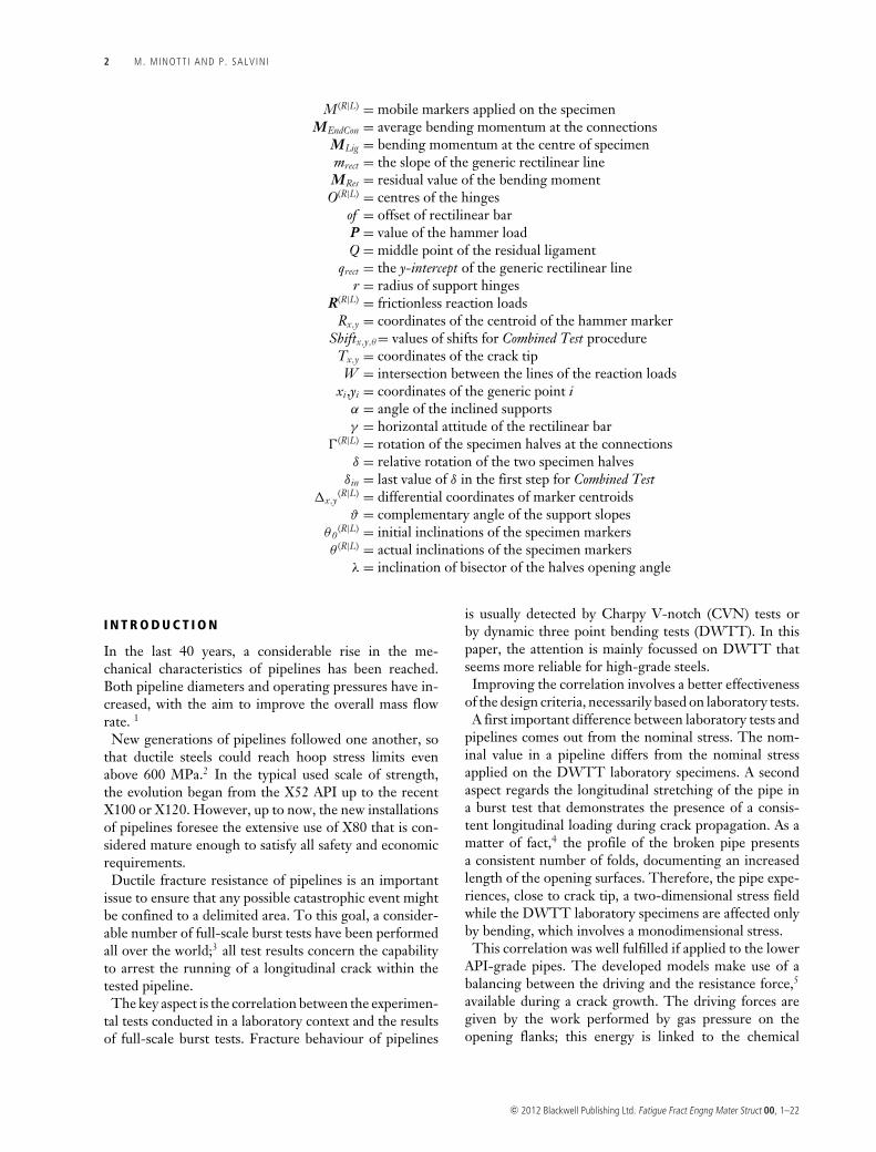
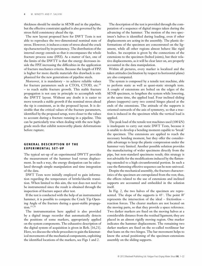
The system is composed by a tensile test machine, ableto perform static as well as quasi-static strength tests.A couple of extensions are bolted on the edges of theSENB specimen, to lengthen the system while lowering,at the same time, the applied load. Four inclined slidingplanes (supports) carry two central hinges placed at theends of the extensions. The attitude of the supports isoriented outwards of the axis of symmetry, so that a trac-tion is induced in the specimen while the vertical load isapplied.
The peak load of the tensile test machines used (100 kN)is inadequate to carry out static DWT Tests, because itis unable to develop a bending moment capable to ‘break’the specimen. The extensions are applied to reach thenecessary bending moment, but they offer the consider-able advantage to keep the plastic compression under thehammer very limited. Another possible solution providesthe manufacturing of wider specimens directly from thepipe, but non-standard specimens result; this strategy isnot advisable for the modifications induced by the flatten-ing extended to a high circumferential portion. In such acase the flattening effective sequence can be non-univocal.
Despite the mechanical assembly, the fracture character-istics of the specimen are extrapolated from the rest; thus,the effects related to the use of extensions and inclinedsupports are accounted and embedded in the solutionitself.
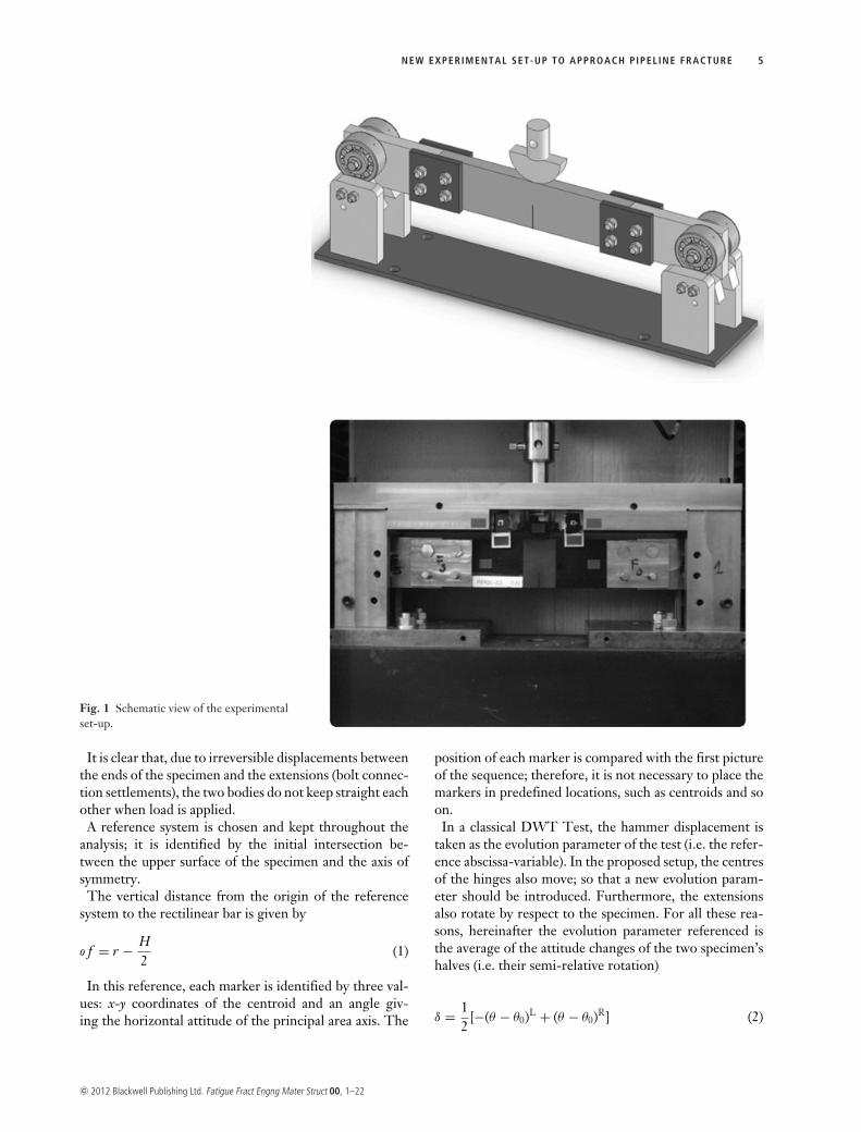
In Fig. 2, the two halves of the specimen are repre-sented. The slope of the supports is 45◦. The point Wrepresents the intersection of the ideal – frictionless –reaction forces. The clearer markers are not located onthe moving parts, so that they provide a space reference.Two darker markers are fixed on the moving halves at aconsiderable distance from the residual ligament; they areplaced in an almost rigidly moving region. One markerindicates the hammer displacement. The remaining twodarker markers are fixed on the so-called rectilinear barthat leans on the two hinges. The bar movement helps toknow the actual positioning of the specimen-extensionsassembly on the sliding supports.
c© 2012 Blackwell Publishing Ltd. Fatigue Fract Engng Mater Struct 00, 1–22
NEW EXPERIMENTAL SET-UP TO APPROACH PIPEL INE FRACTURE 5
Fig. 1 Schematic view of the experimentalset-up.
It is clear that, due to irreversible displacements betweenthe ends of the specimen and the extensions (bolt connec-tion settlements), the two bodies do not keep straight eachother when load is applied.
A reference system is chosen and kept throughout theanalysis; it is identified by the initial intersection be-tween the upper surface of the specimen and the axis ofsymmetry.
The vertical distance from the origin of the referencesystem to the rectilinear bar is given by
o f = r − H2
(1)
In this reference, each marker is identified by three val-ues: x-y coordinates of the centroid and an angle giv-ing the horizontal attitude of the principal area axis. The
position of each marker is compared with the first pictureof the sequence; therefore, it is not necessary to place themarkers in predefined locations, such as centroids and soon.
In a classical DWT Test, the hammer displacement istaken as the evolution parameter of the test (i.e. the refer-ence abscissa-variable). In the proposed setup, the centresof the hinges also move; so that a new evolution param-eter should be introduced. Furthermore, the extensionsalso rotate by respect to the specimen. For all these rea-sons, hereinafter the evolution parameter referenced isthe average of the attitude changes of the two specimen’shalves (i.e. their semi-relative rotation)
δ = 12
[−(θ − θ0)L + (θ − θ0)R] (2)
c© 2012 Blackwell Publishing Ltd. Fatigue Fract Engng Mater Struct 00, 1–22
6 M. MINOTT I AND P. SALV IN I
Fig. 2 Reference values on the experimental set-up.
At any time, the general attitude of the whole system,sustained by the two hinges, can deviate from the initialhorizontal positioning; so that an angle (positive anti-clockwise) is computed from the displacements (referredto the first picture) of the two markers located on therectilinear bar
γ = arctan
[�
(R)y − �
(L)y
�(R)x − �
(L)x
](3)
The vertical displacement of the rectilinear bar is com-puted by the search of the intersection with the y-axis (itis the same to use the left or the right marker L|R, butswitch of sign result)
disp = ∓ tan(γ ) · �(L|R)x + �(L|R)
y (4)
The knowledge of the movements of these two markershelps to get the effective points of contact between therectilinear bar and the two hinges.
To get these contact points, it is first necessary to explicitthe distance between the intersection of the two slidingsupports and the origin of the reference system (pointsF(R) and F(L) in Fig. 2)
L = L0 − 2 · rtan (α/2)
(5)
where r represents the hinge radius.If, during the test, symmetry is not preserved by the
two halves, a non-negligible γ occurs. In such a case, thedistances Lf between the left or right points D (wherethe rectilinear bar touches the hinges) and the initial axisof symmetry is not the same. According to the positive
c© 2012 Blackwell Publishing Ltd. Fatigue Fract Engng Mater Struct 00, 1–22

NEW EXPERIMENTAL SET-UP TO APPROACH PIPEL INE FRACTURE 7
anticlockwise choice, the respective values are
L(L,R)f = r
tan(
α∓γ
2
) ± dispsin (γ )
+[∓dis p + L
2 tan (α)]
sin (α ∓ γ )cos (α) (6)
Due to both the rectilinear bar attitude (γ ) and the ver-tical displacement (disp), the coordinates of the contactpoints between the two hinges and the rectilinear bar are⎧⎪⎨⎪⎩
x(L)D = −L(L)
f cos (γ )
y (L)D = y (L)
D0+ �
(R)y +�
(L)y
2 + L(L)f tan (γ )
⎧⎨⎩
x(R)D = L(R)
f cos (γ )
y (R)D = y (R)
D0+ �
(R)y +�
(L)y
2 − L(R)f tan (γ )
(7)
At this stage, the fundamental information to know arethe actual location of the hinges and the contact pointsbetween the hinges themselves and the sliding supports.
The left and right distances between the hinge-supportcontacts and the rectilinear bar (undeformable but gener-ally non-horizontal) are
GF (L) = rtan
(α−γ
2
) GF (R) = rtan
(α+γ
2
) (8)
Note also that the two left and right triangles GF Dareisosceles so that DF = GF (Fig. 3). The two straight linestouching points F and G have, respectively, the followingparameters:⎧⎨⎩
m(L)GF = tan (α) ; m(R)
GF = − tan (α)
q (L,R)GF = −m(L,R)
GF · x(L,R)B + y (L,R)
B{mbar = tan (γ )
qbar = −mbar · x(L)D + y (L)
D
(9)
where mGF , qGF , mbar and qbar are slopes and y-interceptsfor the GFand the rectilinear bar.
Fig. 3 Overexposure of hinge-support contact region.
The resulting coordinates of left and right points F, are⎧⎪⎪⎨⎪⎪⎩
x(L,R)F =
(q (L,R)
GF − qbar)
(mbar − m(L,R)
GF
)y (L,R)
F = mbar · x(L,R)F + qbar
(10)
Finally, the contact points between the hinges and therectilinear bar are now properly computed⎧⎪⎪⎪⎨⎪⎪⎪⎩
x(L)G = x(L)
F − r cos (α)tan
(α−γ
2
)y (L)
G = y (L)F − r sin (α)
tan(
α−γ
2
)
⎧⎪⎪⎪⎨⎪⎪⎪⎩
x(R)G = x(R)
F + r cos (α)tan
(α+γ
2
)y (R)
G = y (R)F − r sin (α)
tan(
α+γ
2
)(11)
Moreover, the actual locations of the centres of the twohinges are given by the two couples of coordinates, re-spectively,⎧⎪⎪⎪⎨⎪⎪⎪⎩
x(L)O = x(L)
F − r[
cot(
α − γ
2
)cos (γ ) + sin (γ )
]
y (L)O = y (L)
F − r[
cot(
α − γ
2
)sin (γ ) − cos (γ )
]⎧⎪⎪⎪⎨⎪⎪⎪⎩
x(R)O = x(R)
F + r[
cot(
α + γ
2
)cos (γ ) + sin (γ )
]
y (R)O = y (R)
F − r[
cot(
α + γ
2
)sin (γ ) + cos (γ )
](12)
In the same reference system, the effective fracture tipshould be located at every frame. The effective ligament(Lig) is known thanks to a different algorithm applied ondigital images. It identifies the distance between the pointwhere the load is applied and the crack tip as it appearson the surface. In a brief synthesis, the algorithm iden-tifies the crack tip through an extrapolation of a simplepolynomial that fits the crack flanks. 22
The moving markers (M(L|R)) attached on the specimen’shalves are positioned with a ‘rule of thumb’; however, tak-ing advantage of the identification of the markers at thefirst picture (unloaded), one can precisely compute theeffective marker locations on the specimen. An eventualasymmetrical initial disposition of the markers (typically 1mm uncertainty) is a priori corrected by a rigid motion as-sumption; therefore, we assume a perfect symmetry of thetwo halves for an easy writing of the subsequent equations.With this statement in mind, the coordinates of mobilemarkers are given as simple incremental quantities.
As mentioned before, a mobile marker is located on thehammer head, its movement gives the deflection of thespecimen and its coordinates are said Rx and Ry.
In the reasonable hypothesis that the centre of contacton the hammer can only move in the y-direction, by theknowledge of the marker locations and ligament value,
c© 2012 Blackwell Publishing Ltd. Fatigue Fract Engng Mater Struct 00, 1–22
8 M. MINOTT I AND P. SALV IN I
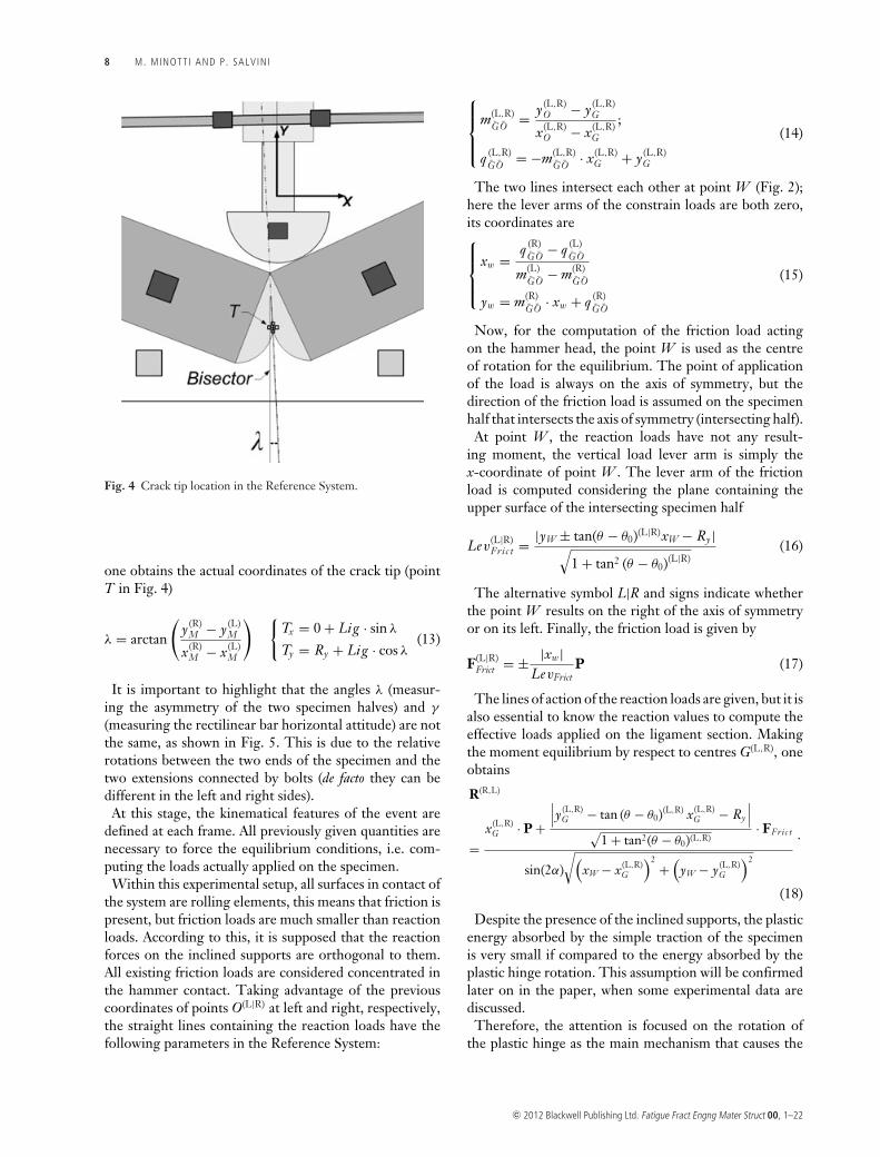
Fig. 4 Crack tip location in the Reference System.
one obtains the actual coordinates of the crack tip (pointT in Fig. 4)
λ = arctan
(y (R)
M − y (L)M
x(R)M − x(L)
M
) {Tx = 0 + Lig · sin λ
Ty = Ry + Lig · cos λ(13)
It is important to highlight that the angles λ (measur-ing the asymmetry of the two specimen halves) and γ
(measuring the rectilinear bar horizontal attitude) are notthe same, as shown in Fig. 5. This is due to the relativerotations between the two ends of the specimen and thetwo extensions connected by bolts (de facto they can bedifferent in the left and right sides).
At this stage, the kinematical features of the event aredefined at each frame. All previously given quantities arenecessary to force the equilibrium conditions, i.e. com-puting the loads actually applied on the specimen.
Within this experimental setup, all surfaces in contact ofthe system are rolling elements, this means that friction ispresent, but friction loads are much smaller than reactionloads. According to this, it is supposed that the reactionforces on the inclined supports are orthogonal to them.All existing friction loads are considered concentrated inthe hammer contact. Taking advantage of the previouscoordinates of points O(L|R) at left and right, respectively,the straight lines containing the reaction loads have thefollowing parameters in the Reference System:
⎧⎪⎪⎨⎪⎪⎩
m(L,R)GO = y (L,R)
O − y (L,R)G
x(L,R)O − x(L,R)
G
;
q (L,R)GO = −m(L,R)
GO · x(L,R)G + y (L,R)
G
(14)
The two lines intersect each other at point W (Fig. 2);here the lever arms of the constrain loads are both zero,its coordinates are⎧⎪⎪⎨⎪⎪⎩
xw = q (R)GO − q (L)
GO
m(L)GO − m(R)
GO
yw = m(R)GO · xw + q (R)
GO
(15)
Now, for the computation of the friction load actingon the hammer head, the point W is used as the centreof rotation for the equilibrium. The point of applicationof the load is always on the axis of symmetry, but thedirection of the friction load is assumed on the specimenhalf that intersects the axis of symmetry (intersecting half).
At point W , the reaction loads have not any result-ing moment, the vertical load lever arm is simply thex-coordinate of point W . The lever arm of the frictionload is computed considering the plane containing theupper surface of the intersecting specimen half
Lev(L|R)Fric t = |yW ± tan(θ − θ0)(L|R)xW − Ry |√
1 + tan2 (θ − θ0)(L|R)(16)
The alternative symbol L|R and signs indicate whetherthe point W results on the right of the axis of symmetryor on its left. Finally, the friction load is given by
F(L|R)Frict = ± |xw|
LevFrictP (17)
The lines of action of the reaction loads are given, but it isalso essential to know the reaction values to compute theeffective loads applied on the ligament section. Makingthe moment equilibrium by respect to centres G(L,R), oneobtains
R(R,L)
=x(L,R)
G · P +
∣∣∣y (L,R)G − tan (θ − θ0)(L,R) x(L,R)
G − Ry
∣∣∣√1 + tan2(θ − θ0)(L,R)
· FFric t
sin(2α)√(
xW − x(L,R)G
)2+(
yW − y (L,R)G
)2
.
(18)
Despite the presence of the inclined supports, the plasticenergy absorbed by the simple traction of the specimenis very small if compared to the energy absorbed by theplastic hinge rotation. This assumption will be confirmedlater on in the paper, when some experimental data arediscussed.
Therefore, the attention is focused on the rotation ofthe plastic hinge as the main mechanism that causes the
c© 2012 Blackwell Publishing Ltd. Fatigue Fract Engng Mater Struct 00, 1–22
NEW EXPERIMENTAL SET-UP TO APPROACH PIPEL INE FRACTURE 9
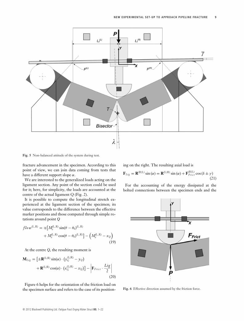
Fig. 5 Non-balanced attitude of the system during test.
fracture advancement in the specimen. According to thispoint of view, we can join data coming from tests thathave a different support slope α.
We are interested to the generalized loads acting on theligament section. Any point of the section could be usedfor it; here, for simplicity, the loads are accounted at thecentre of the actual ligament Q (Fig. 2).
It is possible to compute the longitudinal stretch ex-perienced at the ligament section of the specimen; itsvalue corresponds to the difference between the effectivemarker positions and those computed through simple ro-tations around point Q
f low(L,R) = ∓[M(L,R)x sin(θ − θ0)(L,R)
+ M(L,R)x cos(θ − θ0)(L,R)]−
(M(L,R)
x − xQ
)(19)
At the centre Q, the resulting moment is
MLig = [±R(L|R) sin(α) · (y (L|R)G − yQ
)+ R(L|R) cos(α) · (x(L|R)
G − xQ)]−
∣∣∣∣FFric t · Lig2
∣∣∣∣(20)
Figure 6 helps for the orientation of the friction load onthe specimen surface and refers to the case of its position-
ing on the right. The resulting axial load is
FLig = R(R|L) sin (α) = R(L|R) sin (α) + F(R|L)Fric t cos (δ ± γ )
(21)
For the accounting of the energy dissipated at thebolted connections between the specimen ends and the
Fig. 6 Effective direction assumed by the friction force.
c© 2012 Blackwell Publishing Ltd. Fatigue Fract Engng Mater Struct 00, 1–22
10 M. MINOTT I AND P. SALV IN I
extensions, it is possible to derive the relative rotations.It is assumed that the joints can only be affected by a ro-tation located at the geometric centre of the two plaquesconnecting the two parts (see Fig. 1).
The coordinates of these central points are (Fig. 2)⎧⎪⎪⎨⎪⎪⎩
x(L,R)J = x(L,R)
M ∓ Ls
4cos(δ(L,R))
y (L,R)J = y (L,R)
M − Ls
4sin(δ(L,R))
(22)
where δ(L,R) is the rotation of the two halves, with a positivesign if rotations are anti-clockwise, and Ls is the initiallength of the specimen.
The relative rotations of the two halves of the specimenand the extensions are given by
�(L,R) = arctan
(± y (L,R)
O − y (L,R)J
x(L,R)O − x(L,R)
J
)− δ(L,R) (23)
The bending moments experienced at the extension con-nections are easily computed if considering the appropri-ate lever arm together with the reaction loads
MEndCon =−[R(L) sin(α) ·
(y (L)
G − yJ
)+ R(L) cos(α) ·
(x(L)
G − xJ
)]+[R(R) sin(α) ·
(y (R)
G − yJ
)+ R(R) cos(α) ·
(x(R)
G − xJ
)]2
(24)
From all previous kinematical and dynamical results, allenergies involved in the test can be derived
• Total energy put in the system:ETOT = ∑npicti=2 P(i )·
[Ry(i) − Ry(i − 1)]• Energy of the bending at the ligament section:
ELig =npict∑i=2
MLig (i ) · [δ(i ) − δ(i − 1)] (25)
• Energy lost in the specimen connections: EEndCon =∑npicti=2 MEndCon(i ) · [�(i ) − �(i − 1)]
• Energy lost in overall frictions: EFric t = ∑npicti=2
FFric t(i ) · LevFric t(i ) · [δ(i ) − δ(i − 1)]• Energy associated to longitudinal stretch: EFlow =[∑npict
i=2 R(L) sin (α) f low(L) + R(R) sin (α) f low(R)]
C O M B I N E D T E S T
One of the important drawbacks, connected with the useof inclined supports is that, when the slope is set to highvalues and the crack has not yet started moving, the reac-tion loads can reach considerable values. To get aroundthis difficulty, we explored the possibility to subdivide thetest into two phases.
In the first phase, the load is applied on non-inclinedsupports (α = 0◦) until the crack starts to have a sta-ble propagation. This occurs when the load has reduced
almost to half its maximum value. This condition is ex-perimentally chosen when the relative rotation of the twospecimen halves reaches a fixed value. After that, the testis suspended, the specimen is remounted on the desiredinclined supports and the test is restarted. This split pro-cedure allows the use of very inclined supports, thus ap-proaching the effective persistent state of stress that isexperienced in front of a crack running on a pipeline.This type of procedure is herein called combined test.
To make it evident the advantages embedded in the useof inclined supports, we performed some Finite Elementanalyses on the specimen subjected to large plasticity anddeflections, mounted on differently inclined supports.
There is no need here to model also the bolted connec-tions, so that the model consists of a specimen as long as545 mm with a 12 mm initial indentation. The model ismeshed with 12880 solid elements and solved with an im-plicit Finite Element solver. This elasto-plastic analysis isfocused on the size of the stress persistency region aheadthe crack tip; therefore, the tunneling (non straight crackthrough thickness), the process zone (due to increasing
damage ahead the blunting) and the crack growth, are allunconsidered in the analysis.
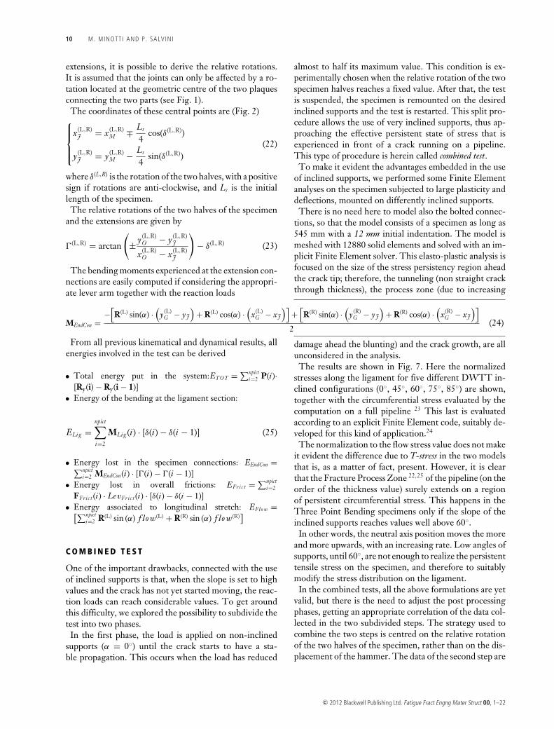
The results are shown in Fig. 7. Here the normalizedstresses along the ligament for five different DWTT in-clined configurations (0◦, 45◦, 60◦, 75◦, 85◦) are shown,together with the circumferential stress evaluated by thecomputation on a full pipeline 23 This last is evaluatedaccording to an explicit Finite Element code, suitably de-veloped for this kind of application.24
The normalization to the flow stress value does not makeit evident the difference due to T-stress in the two modelsthat is, as a matter of fact, present. However, it is clearthat the Fracture Process Zone 22,25 of the pipeline (on theorder of the thickness value) surely extends on a regionof persistent circumferential stress. This happens in theThree Point Bending specimens only if the slope of theinclined supports reaches values well above 60◦.
In other words, the neutral axis position moves the moreand more upwards, with an increasing rate. Low angles ofsupports, until 60◦, are not enough to realize the persistenttensile stress on the specimen, and therefore to suitablymodify the stress distribution on the ligament.
In the combined tests, all the above formulations are yetvalid, but there is the need to adjust the post processingphases, getting an appropriate correlation of the data col-lected in the two subdivided steps. The strategy used tocombine the two steps is centred on the relative rotationof the two halves of the specimen, rather than on the dis-placement of the hammer. The data of the second step are
c© 2012 Blackwell Publishing Ltd. Fatigue Fract Engng Mater Struct 00, 1–22
NEW EXPERIMENTAL SET-UP TO APPROACH PIPEL INE FRACTURE 11
Fig. 7 Stress trend on the ligament forsome support angles.
queued to the data of the first one, so that a continuousand monotonic trend in the rotation of the specimen isachieved. The step switch is planned so that the stablepropagation of the crack happens almost entirely whenthe supports are inclined.
It is necessary to introduce a rigid shift on the markerlocation (since it is really impossible to reposition thespecimen in the same location when restarting the test),so that the first configuration of the second step overlapswith the last configuration of the first one.
Therefore, any marker is subjected to appropriate shiftsand rotation.
Shiftx = RFirstx (end) − RSecond
x (cut) (26)
Shifty = displFirst (end) − displSecond (cut)
−
(�
(L)y (cut) + �
(R)y (cut) · �
(R)x (1)
�(L)x (1)
)(
1 + �(R)x (1)
�(L)x (1)
) (27)
Shi f tδ = γ First (end ) − γ Second (c ut) (28)
The initial distance between the external hinges is nomore equal to L0, since it should consider the displace-ments occurred in the first step, that is to say, the rotationson the ligament and those on the bolted connections
LCT0 = LS · cos(δin) + (LS − L0) · cos
(�(R) + �(L)
2+ δin
)(29)
When reloading the specimen during the second step,it is necessary to identify the frame in which the relativerotation of the two halves is just higher than the final valueexperienced in the first step, we label this frame as cut.
When the above conditions are fulfilled, the estimationof all energy rates belonging to the two experimental steps
is combined together. Being energy an incremental quan-tities, previous eq.s (25) become:
Ei =
⎡⎢⎢⎢⎢⎢⎢⎢⎢⎢⎣
EI
⎡⎢⎣
1...
endI
⎤⎥⎦
EI I
⎛⎜⎝EI (endI ) +
⎡⎢⎣
c ut...
endI I
⎤⎥⎦⎞⎟⎠
⎤⎥⎥⎥⎥⎥⎥⎥⎥⎥⎦
with
i = [TOT, Lig, EndCon, Frict, Flow
]
(30)
E X P E R I M E N T A L M E A S U R E M E N T S
The experimental data here discussed are relative to amaximum value of the support inclination equal to 60◦.Even if it is clear, by Fig. 7, that the full satisfaction ofthe persistency of the stress ahead the crack is fulfilledonly above 60◦, here it is important to highlight that themeasurements carried on with inclined supports can besuccessfully compared with the standard DWTT, if rel-ative rotations are considered like the evolution parame-ter. The comparison among differently-inclined supporttests, all together, helps to have an insight of how repre-sentative are the fracture features deduced by DWT Test(rapidly-decreasing nominal stress field) of fractures run-ning on pipelines where persistent stress fields act in thefracturing region.
The limit on the support slopes is due to the inadequatestructural stiffness of the present prototypal set-up. A newexperimental set-up that can operate with supports up to85◦ is under testing. However, we can claim that the stresspersistency has a remarkable effect on crack growth.
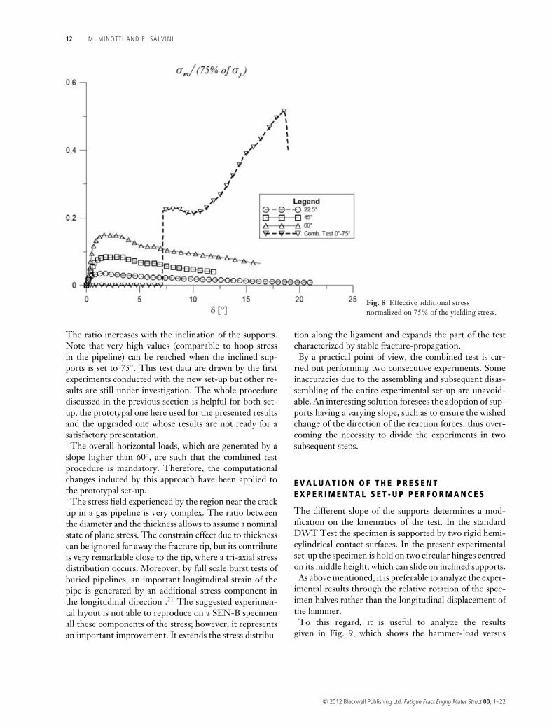
In Fig. 8 it is shown, for the X100 specimens, the effec-tive ratio between two nominal stresses: the stress due tohorizontal loads given by support reactions and the hoopstress in a pipeline taken as the 75% of the yield stress.
c© 2012 Blackwell Publishing Ltd. Fatigue Fract Engng Mater Struct 00, 1–22
12 M. MINOTT I AND P. SALV IN I
Fig. 8 Effective additional stressnormalized on 75% of the yielding stress.
The ratio increases with the inclination of the supports.Note that very high values (comparable to hoop stressin the pipeline) can be reached when the inclined sup-ports is set to 75◦. This test data are drawn by the firstexperiments conducted with the new set-up but other re-sults are still under investigation. The whole procedurediscussed in the previous section is helpful for both set-up, the prototypal one here used for the presented resultsand the upgraded one whose results are not ready for asatisfactory presentation.
The overall horizontal loads, which are generated by aslope higher than 60◦, are such that the combined testprocedure is mandatory. Therefore, the computationalchanges induced by this approach have been applied tothe prototypal set-up.
The stress field experienced by the region near the cracktip in a gas pipeline is very complex. The ratio betweenthe diameter and the thickness allows to assume a nominalstate of plane stress. The constrain effect due to thicknesscan be ignored far away the fracture tip, but its contributeis very remarkable close to the tip, where a tri-axial stressdistribution occurs. Moreover, by full scale burst tests ofburied pipelines, an important longitudinal strain of thepipe is generated by an additional stress component inthe longitudinal direction .21 The suggested experimen-tal layout is not able to reproduce on a SEN-B specimenall these components of the stress; however, it representsan important improvement. It extends the stress distribu-
tion along the ligament and expands the part of the testcharacterized by stable fracture-propagation.
By a practical point of view, the combined test is car-ried out performing two consecutive experiments. Someinaccuracies due to the assembling and subsequent disas-sembling of the entire experimental set-up are unavoid-able. An interesting solution foresees the adoption of sup-ports having a varying slope, such as to ensure the wishedchange of the direction of the reaction forces, thus over-coming the necessity to divide the experiments in twosubsequent steps.
E V A L U A T I O N O F T H E P R E S E N TE X P E R I M E N T A L S E T - U P P E R F O R M A N C E S
The different slope of the supports determines a mod-ification on the kinematics of the test. In the standardDWT Test the specimen is supported by two rigid hemi-cylindrical contact surfaces. In the present experimentalset-up the specimen is hold on two circular hinges centredon its middle height, which can slide on inclined supports.
As above mentioned, it is preferable to analyze the exper-imental results through the relative rotation of the spec-imen halves rather than the longitudinal displacement ofthe hammer.
To this regard, it is useful to analyze the resultsgiven in Fig. 9, which shows the hammer-load versus
c© 2012 Blackwell Publishing Ltd. Fatigue Fract Engng Mater Struct 00, 1–22
NEW EXPERIMENTAL SET-UP TO APPROACH PIPEL INE FRACTURE 13
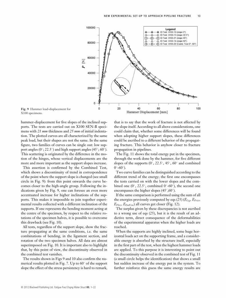
Fig. 9 Hammer load-displacement forX100 specimens.
hammer-displacement for five slopes of the inclined sup-ports. The tests are carried out on X100 SEN-B speci-mens with 21 mm thickness and 25 mm of initial indenta-tion. The plotted curves are all characterized by the samepeak load, but their shapes are not the same. In the samefigure, two families of curves can be single out: low sup-port angles (0◦; 22.5◦) and high support angles (45◦; 60◦).This scattering is originated by the difference in the mo-tion of the hinges, whose vertical displacements are themore and more important as the support slopes increase.
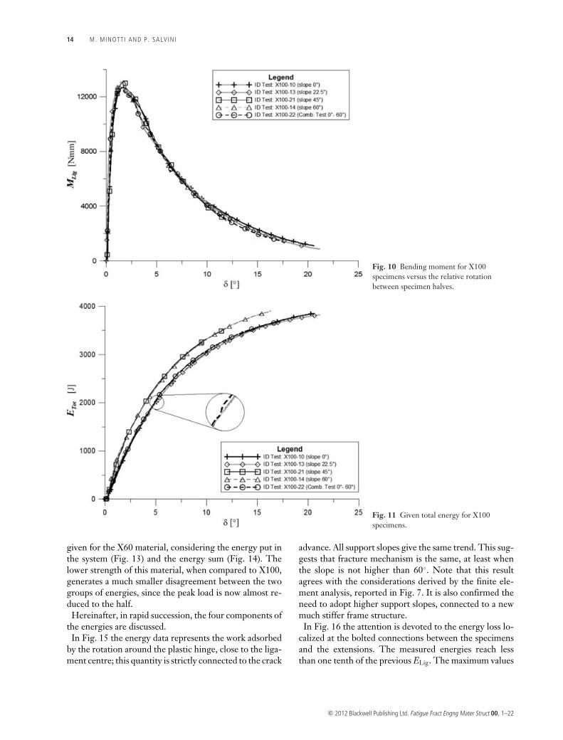
This assertion is confirmed by the Combined Test,which shows a discontinuity of trend in correspondenceof the point where the support slope is changed (see smallcircle in Fig. 9): from this point onwards the curve be-comes closer to the high-angle group. Following the in-dications given by Fig. 9, one can foresee an even moreaccentuated increase for higher inclinations of the sup-ports. This makes it impossible to join together experi-mental results collected with a different inclination of thesupports. If one represents the bending moment acting atthe centre of the specimen, by respect to the relative ro-tations of the specimen halves, it is possible to overcomethis drawback (see Fig. 10).
All tests, regardless of the support slope, show the frac-ture propagating at the same conditions, i.e. the samecombinations of bending, in the ligament section, androtation of the two specimen halves. All data are almostsuperimposed on Fig. 10. It is important also to highlightthat, by this point of view, the discontinuity observed inthe combined test vanishes.
The results shown in Figs 9 and 10 also confirm the nu-merical results plotted in Fig. 7. Up to 60◦ of the supportslope the effect of the stress persistency is hard to remark,
that is to say that the work of fracture is not affected bythe slope itself. According to all above considerations, onecould claim that, whether some differences will be foundwhen adopting higher support slopes, these differencescould be ascribed to a different behavior of the propagat-ing fracture. This behavior is anyhow closer to fracturepropagation in pipelines.
The Fig. 11 shows the total energy put in the specimen,through the work done by the hammer, for five differentslopes of the supports (0◦, 22.5◦, 45◦, 60◦ and combined0◦-60◦).
Two curve families can be distinguished according to thedifferent trend of the energy; the first one encompassesthe tests carried on with the lower slopes and the com-bined one (0◦, 22.5◦, combined 0◦-60◦), the second oneencompasses the higher slopes (45◦,60◦).
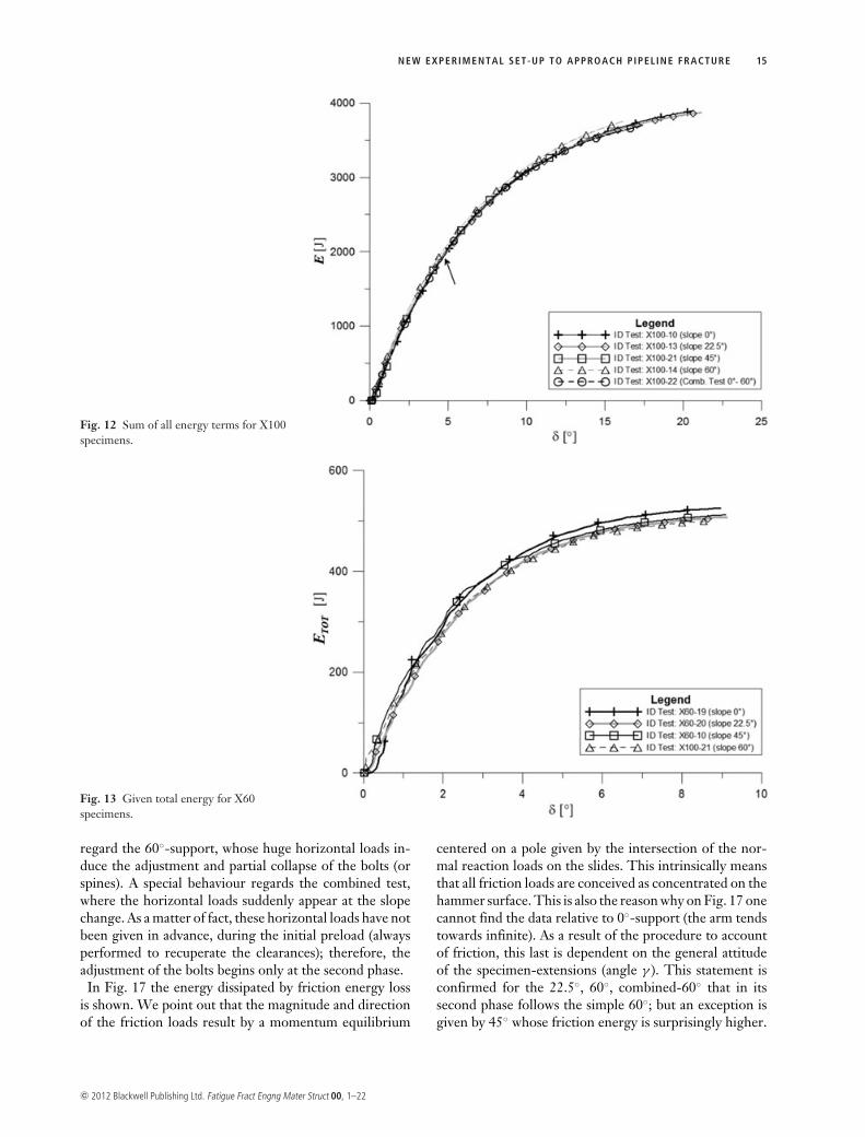
If the same comparison is performed using the sum of allthe energies previously computed by eqs (25) (ELig, EFrict,EFlow, EEndCon) all curves get closer (Fig. 12).
The surplus given by these discrepancies is not ascribedto a wrong use of eqs (25), but it is the result of an ad-dictive term, direct consequence of the deformabilitiesof the experimental apparatus when the higher loads arereached.
When the supports are highly inclined, some huge hor-izontal loads act on the supporting frame, and a consider-able energy is absorbed by the structure itself, especiallyin the first part of the test, when the highest hammer loadsare applied. To this purpose it is interesting to point outthe discontinuity observed in the combined test of Fig. 11(a small circle helps the identification) that shows a smallbut sudden increase of the energy put in the system. Tofurther reinforce this guess the same energy results are
c© 2012 Blackwell Publishing Ltd. Fatigue Fract Engng Mater Struct 00, 1–22
14 M. MINOTT I AND P. SALV IN I
Fig. 10 Bending moment for X100specimens versus the relative rotationbetween specimen halves.
Fig. 11 Given total energy for X100specimens.
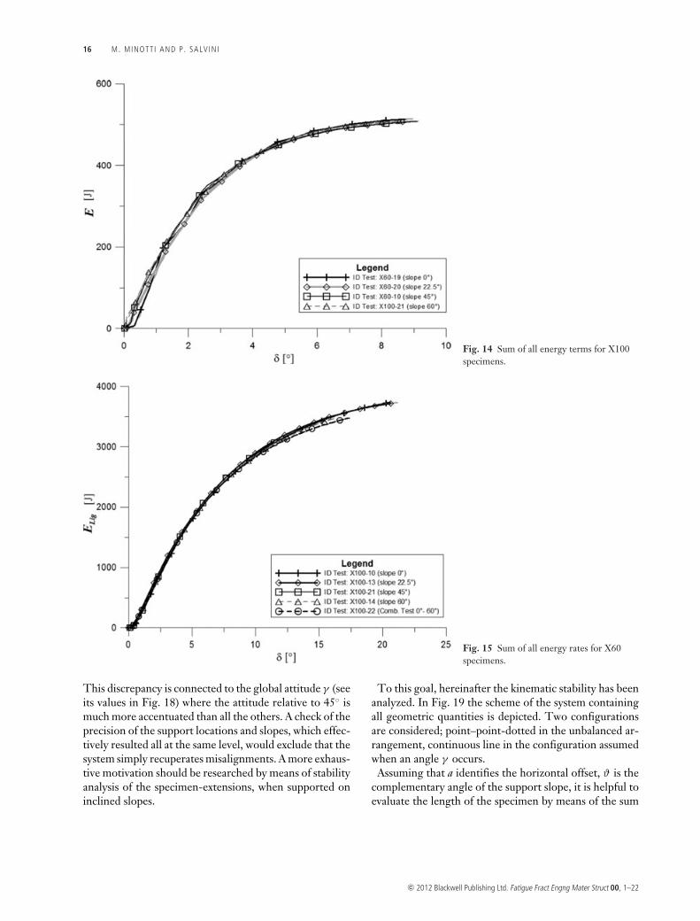
given for the X60 material, considering the energy put inthe system (Fig. 13) and the energy sum (Fig. 14). Thelower strength of this material, when compared to X100,generates a much smaller disagreement between the twogroups of energies, since the peak load is now almost re-duced to the half.
Hereinafter, in rapid succession, the four components ofthe energies are discussed.
In Fig. 15 the energy data represents the work adsorbedby the rotation around the plastic hinge, close to the liga-ment centre; this quantity is strictly connected to the crack
advance. All support slopes give the same trend. This sug-gests that fracture mechanism is the same, at least whenthe slope is not higher than 60◦. Note that this resultagrees with the considerations derived by the finite ele-ment analysis, reported in Fig. 7. It is also confirmed theneed to adopt higher support slopes, connected to a newmuch stiffer frame structure.
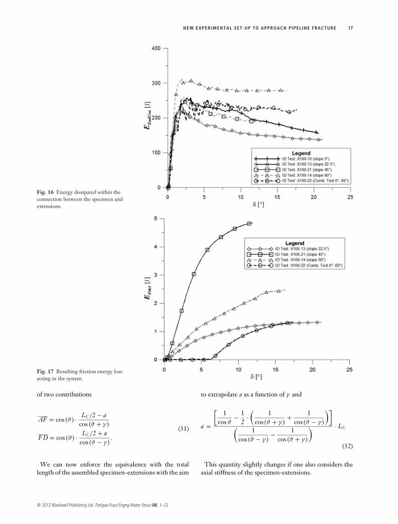
In Fig. 16 the attention is devoted to the energy loss lo-calized at the bolted connections between the specimensand the extensions. The measured energies reach lessthan one tenth of the previous ELig. The maximum values
c© 2012 Blackwell Publishing Ltd. Fatigue Fract Engng Mater Struct 00, 1–22
NEW EXPERIMENTAL SET-UP TO APPROACH PIPEL INE FRACTURE 15
Fig. 12 Sum of all energy terms for X100specimens.
Fig. 13 Given total energy for X60specimens.
regard the 60◦-support, whose huge horizontal loads in-duce the adjustment and partial collapse of the bolts (orspines). A special behaviour regards the combined test,where the horizontal loads suddenly appear at the slopechange. As a matter of fact, these horizontal loads have notbeen given in advance, during the initial preload (alwaysperformed to recuperate the clearances); therefore, theadjustment of the bolts begins only at the second phase.
In Fig. 17 the energy dissipated by friction energy lossis shown. We point out that the magnitude and directionof the friction loads result by a momentum equilibrium
centered on a pole given by the intersection of the nor-mal reaction loads on the slides. This intrinsically meansthat all friction loads are conceived as concentrated on thehammer surface. This is also the reason why on Fig. 17 onecannot find the data relative to 0◦-support (the arm tendstowards infinite). As a result of the procedure to accountof friction, this last is dependent on the general attitudeof the specimen-extensions (angle γ ). This statement isconfirmed for the 22.5◦, 60◦, combined-60◦ that in itssecond phase follows the simple 60◦; but an exception isgiven by 45◦ whose friction energy is surprisingly higher.
c© 2012 Blackwell Publishing Ltd. Fatigue Fract Engng Mater Struct 00, 1–22
16 M. MINOTT I AND P. SALV IN I
Fig. 14 Sum of all energy terms for X100specimens.
Fig. 15 Sum of all energy rates for X60specimens.
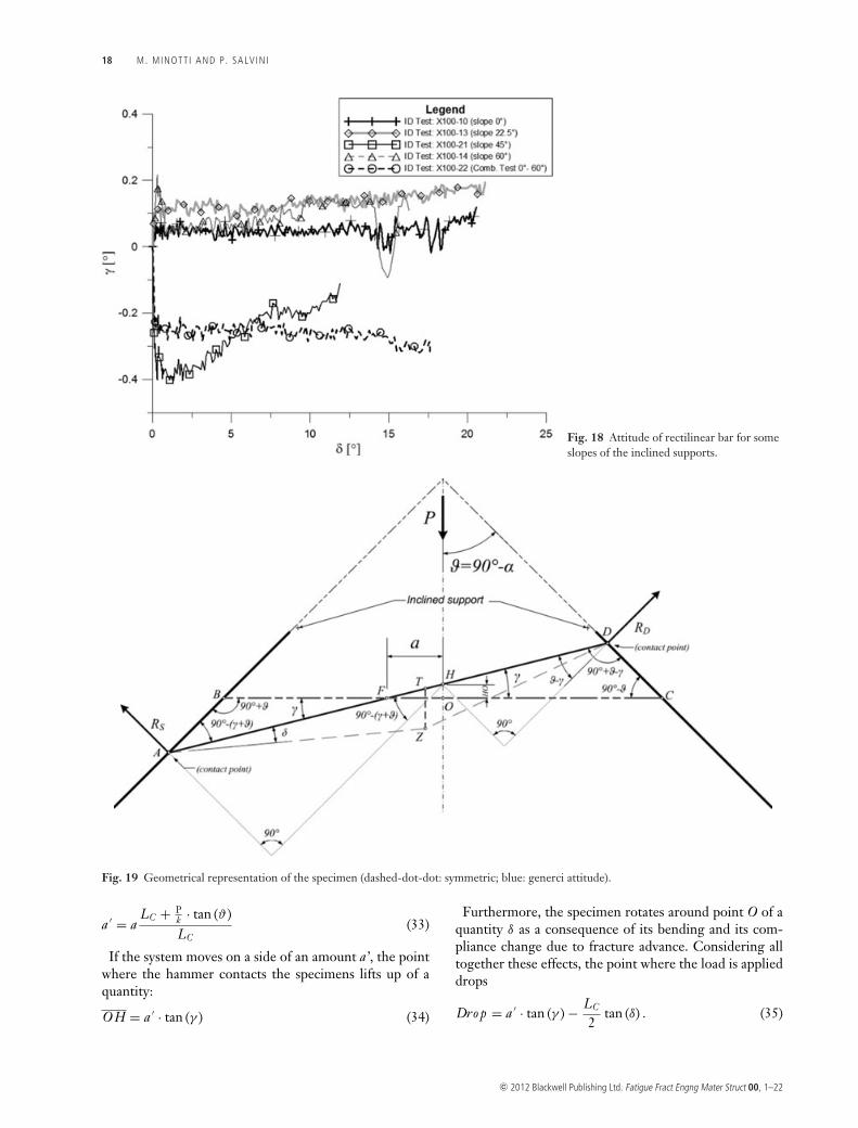
This discrepancy is connected to the global attitude γ (seeits values in Fig. 18) where the attitude relative to 45◦ ismuch more accentuated than all the others. A check of theprecision of the support locations and slopes, which effec-tively resulted all at the same level, would exclude that thesystem simply recuperates misalignments. A more exhaus-tive motivation should be researched by means of stabilityanalysis of the specimen-extensions, when supported oninclined slopes.
To this goal, hereinafter the kinematic stability has beenanalyzed. In Fig. 19 the scheme of the system containingall geometric quantities is depicted. Two configurationsare considered; point–point-dotted in the unbalanced ar-rangement, continuous line in the configuration assumedwhen an angle γ occurs.
Assuming that a identifies the horizontal offset, ϑ is thecomplementary angle of the support slope, it is helpful toevaluate the length of the specimen by means of the sum
c© 2012 Blackwell Publishing Ltd. Fatigue Fract Engng Mater Struct 00, 1–22
NEW EXPERIMENTAL SET-UP TO APPROACH PIPEL INE FRACTURE 17
Fig. 16 Energy dissipated within theconnection between the specimen andextensions.
Fig. 17 Resulting friction energy lossacting in the system.
of two contributions
AF = cos (ϑ) · LC/2 − acos (ϑ + γ )
F D = cos (ϑ) · LC/2 + acos (ϑ − γ )
.
(31)
We can now enforce the equivalence with the totallength of the assembled specimen-extensions with the aim
to extrapolate a as a function of γ and
a =
[1
cos ϑ− 1
2·(
1cos (ϑ + γ )
+ 1cos (ϑ − γ )
)](
1cos (ϑ − γ )
− 1cos (ϑ + γ )
) · LC
(32)
This quantity slightly changes if one also considers theaxial stiffness of the specimen-extensions.
c© 2012 Blackwell Publishing Ltd. Fatigue Fract Engng Mater Struct 00, 1–22
18 M. MINOTT I AND P. SALV IN I
Fig. 18 Attitude of rectilinear bar for someslopes of the inclined supports.
Fig. 19 Geometrical representation of the specimen (dashed-dot-dot: symmetric; blue: generci attitude).
a ′ = aLC + P
k · tan (ϑ)LC
(33)
If the system moves on a side of an amount a’, the pointwhere the hammer contacts the specimens lifts up of aquantity:
O H = a ′ · tan (γ ) (34)
Furthermore, the specimen rotates around point O of aquantity δ as a consequence of its bending and its com-pliance change due to fracture advance. Considering alltogether these effects, the point where the load is applieddrops
Dro p = a ′ · tan (γ ) − LC
2tan (δ) . (35)
c© 2012 Blackwell Publishing Ltd. Fatigue Fract Engng Mater Struct 00, 1–22
NEW EXPERIMENTAL SET-UP TO APPROACH PIPEL INE FRACTURE 19
Fig. 20 Value of the Drop versus the angleof the inclined supports.
This last expression contains a small approximation sinceO H is considered very close to TZwhen δ and γ are smallcompared to.
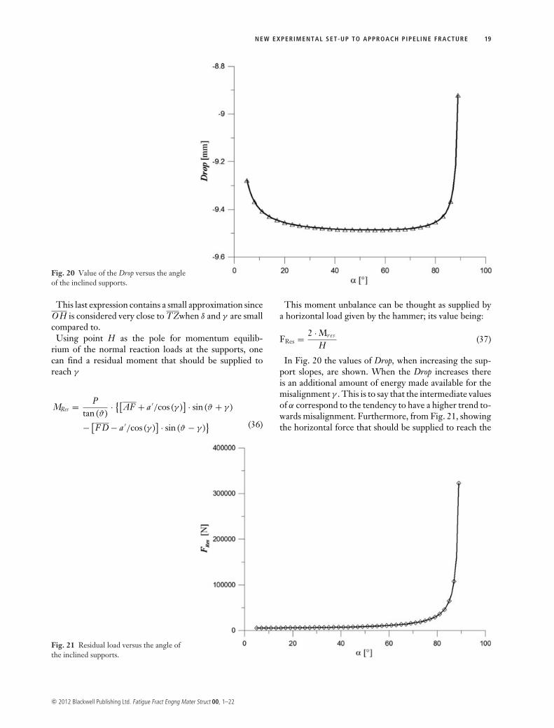
Using point H as the pole for momentum equilib-rium of the normal reaction loads at the supports, onecan find a residual moment that should be supplied toreach γ
MRes = Ptan (ϑ)
· {[AF + a ′/cos (γ )] · sin (ϑ + γ )
− [F D − a ′/cos (γ )] · sin (ϑ − γ )
} (36)
This moment unbalance can be thought as supplied bya horizontal load given by the hammer; its value being:
FRes = 2 · Mres
H(37)
In Fig. 20 the values of Drop, when increasing the sup-port slopes, are shown. When the Drop increases thereis an additional amount of energy made available for themisalignment γ . This is to say that the intermediate valuesof α correspond to the tendency to have a higher trend to-wards misalignment. Furthermore, from Fig. 21, showingthe horizontal force that should be supplied to reach the
Fig. 21 Residual load versus the angle ofthe inclined supports.
c© 2012 Blackwell Publishing Ltd. Fatigue Fract Engng Mater Struct 00, 1–22
20 M. MINOTT I AND P. SALV IN I
misalignment, we see that this contribution is stable for awhile, then it increases significantly. The two aspects to-gether indicate that the perfectly horizontal configurationis always stable; but the maximum tendency towards mis-alignment is reached when the support slopes approach45–50◦, as it results from experiments.
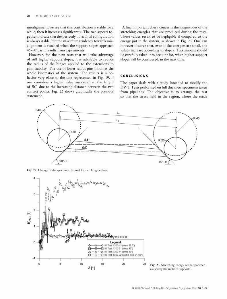
However, for the next tests that will take advantageof still higher support slopes, it is advisable to reducethe radius of the hinges applied to the extensions togain stability. The use of lower radius pins modifies thewhole kinematics of the system. The results is a be-havior very close to the one represented in Fig. 19, ifone considers a higher value associated to the lengthof BC, due to the increasing distance between the twocontact points. Fig. 22 shows graphically the previousstatement.
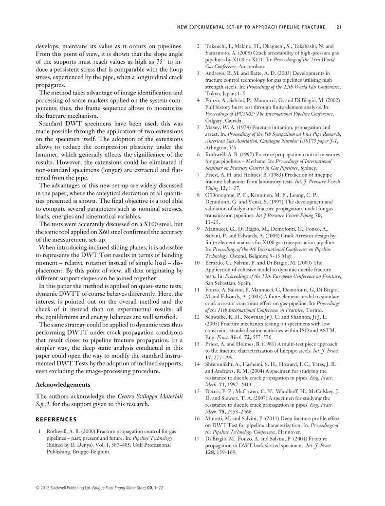
A final important check concerns the magnitudes of thestretching energies that are produced during the tests.These values result to be negligible if compared to theenergy put in the system, as shown in Fig. 23. One canhowever observe that, even if the energies are small, thevalues increase according to slopes. This amount shouldbe carefully taken into account for, when higher supportslopes will be considered, in the next time.
C O N C L U S I O N S
The paper deals with a study intended to modify theDWT Tests performed on full thickness specimens takenfrom pipelines. The objective is to arrange the testso that the stress field in the region, where the crack
Fig. 22 Change of the specimen disposal for two hinge radius.
Fig. 23 Stretching energy of the specimencaused by the inclined supports.
c© 2012 Blackwell Publishing Ltd. Fatigue Fract Engng Mater Struct 00, 1–22
NEW EXPERIMENTAL SET-UP TO APPROACH PIPEL INE FRACTURE 21
develops, maintains its value as it occurs on pipelines.From this point of view, it is shown that the slope angleof the supports must reach values as high as 75◦ to in-duce a persistent stress that is comparable with the hoopstress, experienced by the pipe, when a longitudinal crackpropagates.
The method takes advantage of image identification andprocessing of some markers applied on the system com-ponents; thus, the frame sequence allows to monitorizethe fracture mechanism.
Standard DWT specimens have been used; this wasmade possible through the application of two extensionson the specimen itself. The adoption of the extensionsallows to reduce the compression plasticity under thehammer, which generally affects the significance of theresults. However, the extensions could be eliminated ifnon-standard specimens (longer) are extracted and flat-tened from the pipe.
The advantages of this new set-up are widely discussedin the paper, where the analytical derivation of all quanti-ties presented is shown. The final objective is a tool ableto compute several parameters such as nominal stresses,loads, energies and kinematical variables.
The tests were accurately discussed on a X100 steel, butthe same tool applied on X60 steel confirmed the accuracyof the measurement set-up.
When introducing inclined sliding planes, it is advisableto represents the DWT Test results in terms of bendingmoment – relative rotation instead of simple load – dis-placement. By this point of view, all data originating bydifferent support slopes can be joined together.
In this paper the method is applied on quasi-static tests;dynamic DWTT of course behaves differently. Here, theinterest is pointed out on the overall method and thecheck of it instead than on experimental results: allthe equilibriums and energy balances are well satisfied.
The same strategy could be applied to dynamic tests thusperforming DWTT under crack propagation conditionsthat result closer to pipeline fracture propagation. In asimpler way, the deep static analysis conducted in thispaper could open the way to modify the standard instru-mented DWT Tests by the adoption of inclined supports,even excluding the image-processing procedure.
Acknowledgements
The authors acknowledge the Centro Sviluppo MaterialiS.p.A. for the support given to this research.
R E F E R E N C E S
1 Rothwell, A. B. (2000) Fracture propagation control for gaspipelines – past, present and future. In: Pipeline Technology(Edited by R. Denys). Vol. 1, 387–405. Gulf ProfessionalPublishing, Brugge-Belgium.
2 Takeuchi, I., Makino, H., Okaguchi, S., Takahashi, N. andYamamoto, A. (2006) Crack arrestability of high-pressure gaspipelines by X100 or X120. In: Proceedings of the 23rd WorldGas Conference, Amsterdam.
3 Andrews, R. M. and Batte, A. D. (2003) Developments infracture control technology for gas pipelines utilising highstrength steels. In: Proceedings of the 22th World Gas Conference,Tokyo, Japan; 1–5.
4 Fonzo, A., Salvini, P., Mannucci, G. and Di Biagio, M. (2002)Full history burst test through finite element analysis. In:Proceedings of IPC2002: The International Pipeline Conference,Calgary, Canada.
5 Maxey, W. A. (1974) Fracture initiation, propagation andarrest. In: Proceedings of the 5th Symposium on Line Pipe Research,American Gas Association. Catalogue Number L30175 paper J-1,Arlington, VA.
6 Rothwell, A. B. (1997) Fracture propagation control measuresfor gas pipelines – Methane. In: Proceedings of InternationalSeminar on Fracture Control in Gas Pipelines, Sydney.
7 Priest, A. H. and Holmes, B. (1983) Prediction of linepipefracture behaviour from laboratory tests. Int. J. Pressure VesselsPiping 12, 1–27.
8 O’Donoghue, P. E., Kanninen, M. F., Leung, C. P.,Demofonti, G. and Venzi, S. (1997) The development andvalidation of a dynamic fracture propagation model for gastransmission pipelines. Int J Pressure Vessels Piping 70,11–25.
9 Mannucci, G., Di Biagio, M., Demofonti, G., Fonzo, A.,Salvini, P. and Edwards, A. (2004) Crack Arrestor design byfinite element analysis for X100 gas transportation pipeline.In: Proceedings of the 4th International Conference on PipelineTechnology, Ostend, Belgium; 9–13 May.
10 Berardo, G., Salvini, P. and Di Biagio, M. (2000) TheApplication of cohesive model to dynamic ductile fracturetests. In: Proceedings of the 13th European Conference on Fracture,San Sebastian, Spain.
11 Fonzo, A, Salvini, P, Mannucci, G, Demofonti, G, Di Biagio,M and Edwards, A. (2005) A finite element model to simulatecrack arrestor constraint effect on gas-pipeline. In: Proceedingsof the 11th International Conference on Fracture, Torino.
12 Schwalbe, K. H., Newman Jr J. C. and Shannon, Jr J. L.(2005) Fracture mechanics testing on specimens with lowconstraint–standardisation activities within ISO and ASTM.Eng. Fract. Mech. 72, 557–576.
13 Priest, A. and Holmes, B. (1981) A multi-test piece approachto the fracture characterization of linepipe steels. Int. J. Fract.17, 277–299.
14 Shterenlikht, A., Hashemi, S. H., Howard, I. C., Yates, J. R.and Andrews, R. M. (2004) A specimen for studying theresistance to ductile crack propagation in pipes. Eng. Fract.Mech. 71, 1997–2013.
15 Darcis, P. P., McCowan, C. N., Windhoff, H., McColskey, J.D. and Siewert, T. A. (2007) A specimen for studying theresistance to ductile crack propagation in pipes. Eng. Fract.Mech. 75, 2453–2468.
16 Minotti, M. and Salvini, P. (2011) Deep fracture profile effecton DWT Test for pipeline characterization. In: Proceedings ofthe Pipeline Technology Conference, Hannover.
17 Di Biagio, M., Fonzo, A. and Salvini, P. (2004) Fracturepropagation in DWT back slotted specimens. Int. J. Fract.128, 159–169.
c© 2012 Blackwell Publishing Ltd. Fatigue Fract Engng Mater Struct 00, 1–22
22 M. MINOTT I AND P. SALV IN I
18 Xu, S., Bouchard, R. and Tyson, W. R. (2007) Simplifiedsingle-specimen method for evaluating CTOA. Eng. Fract.Mech. 74, 2459–2464.
19 Martinelli, A. and Venzi, S. (2001) Dependence of J tearingmodulus, CTOA, and total fracture energy on specimendimension. Eng. Fract. Mech. 68, 1575–1590.
20 Newman, J. C., James, M. A. and Zerbst, U. (2003) A reviewof the CTOD/CTOA fracture criterion. Eng. Fract. Mech. 70,371–385.
21 Marotta, E., Minotti, M. and Salvini, P. (2011) Effect offracture tunneling in DWT Tests. Eng. Fract. Mech. Vol. 81,pp. 33–42, February 2012.
22 Salvini, P., Berardo, G., Demofonti, G. and Mannucci, G.(1999) A fracture process zone model for CTOA analysis. In:Proceedings of the International Conference On Fracture Damage
Mechanics, Queen Mary & West field College University ofLondon–London (UK); July 1999.
23 Martinelli, A. and Venzi, S. (1996) Tearing modulus,J-integral, CTOA and crack profile shape obtained from theload-displacement curve only. Eng. Fract. Mech. 53, 263–277.
24 Berardo, G., Salvini, P., Mannucci, G. and Demofonti, G.(2000) On longitudinal propagation of a ductile fracture in agas line pipe: numerical and experimental analysis. In:Proceedings of the International Pipeline Conference IPC2000,Calgary.
25 Fontana, A., Minotti, M. and Salvini, P. (2010) CohesiveRelease Loads in a General Finite Element Model of aPropagating Crack. J. Key Eng. Mater. 417–418,517–520.
c© 2012 Blackwell Publishing Ltd. Fatigue Fract Engng Mater Struct 00, 1–22