Embed Size (px)
Citation preview

New dynamic zoom calibration technique for a stereo-vision based multi-view 3D modeling system
Tao Xian, Soon-Yong Park, Murali Subbarao
Dept. of Electrical & Computer Engineering*
State Univ. of New York at Stony Brook, Stony Brook, NY, USA 11794-2350
ABSTRACT A new technique is proposed for calibrating a 3D modeling system with variable zoom based on multi-view stereo image analysis. The 3D modeling system uses a stereo camera with variable zoom setting and a turntable for rotating an object. Given an object whose complete 3D model (mesh and texture-map) needs to be generated, the object is placed on the turntable and stereo images of the object are captured from multiple views by rotating the turntable. Partial 3D models generated from different views are integrated to obtain a complete 3D model of the object. Changing the zoom to accommodate objects of different sizes and at different distances from the stereo camera changes several internal camera parameters such as focal length and image center. Also, the parameters of the rotation axis of the turntable changes. We present camera calibration techniques for estimating the camera parameters and the rotation axis for different zoom settings. The Perspective Projection Matrices (PPM) of the cameras are calibrated at a selected set of zoom settings. The PPM is decomposed into intrinsic parameters, orientation angles, and translation vectors. Camera parameters at an arbitrary intermediate zoom setting are estimated from the nearest calibrated zoom positions through interpolation. A performance evaluation of this technique is presented with experimental results. We also present a refinement technique for stereo rectification that improves partial shape recovery. And the rotation axis of multi-view at different zoom setting is estimated without further calibration. Complete 3D models obtained with our techniques are presented. Keywords: Stereo vision, 3D modeling, dynamic zoom calibration, multi-view rotation axis estimation
1. INTRODUCTION Recent advances in consumer digital cameras have made low-cost 3D modeling systems feasible. Conventional 3D modeling techniques use a fixed zoom setting in 3D reconstruction. For objects at different distances and/or of different sizes, a vision system with variable zoom is critical for 3D modeling. In the case of fixed zoom setting, the relative positions of lens components are static. When the zoom setting changes, the camera parameters also vary. To extend the fixed zoom setting camera model to adjustable zoom settings, several algorithms have been presented. Wilson and Shafer 1, 2 introduced an iterative trial and error procedure in which four camera parameters are selected. These camera parameters are -- the effective focal length f , the image center ),( 00 vu , and the translation along the optical axis 3T . Up to a 5th degree polynomial is used to estimate the camera parameters from fixed sampled points. Atienza and Zelinsky 3 extended this calibration technique to gaze detection under the assumption that the orientation of the camera coordinate remains unchanged during zoom change. However when the optical configuration of a vision system changes, this assumption is not valid, and a trial and error procedure will be needed to determine the critical parameters. There are several main problems in employing variable/dynamic zoom in 3D modeling. First, many internal camera parameters vary nonlinearly with different zoom settings. Their variations are too complex to be expressed analytically, even for a simple lens system. Second, the relation between the camera coordinate system and the turntable rotation axis
* E-mail: {txian, parksy, murali}@ece.sunysb.edu; Tel: 1 631 632-9149; WWW: www.ece.sunysb.edu/~cvl

changes as it wobbles. Another difficulty arises from the inaccurate and non-linear mechanical control mechanism of a consumer camera. The residual error in positioning the zoom lens by the driving motor cannot be ignored. The partial shape of a single view can be reconstructed from stereo images using a stereo matching technique. Stereo image rectification utilizes the epipolar geometry to reduce the search dimension of stereo matching from 2D to 1D, and also decreases the possibility of mismatches. In our research, we adopted a compact rectification algorithm for stereo pairs proposed by Fusiello et al. 4. The rectification is based on the camera’s intrinsic parameters, mutual position, and orientation. However, rectification imposes a higher accuracy requirement on camera parameters. Due to the non-linearity of lenses and the inaccuracy of mechanical parts, parameters from dynamic estimation are not accurate enough for a perfect rectification. A refinement based on vertical profile SSD is presented to reconstruct the partial shape from estimated projection matrix. For registering and integrating partial shapes, the rotation axis is estimated without further multi-view calibration. In this paper, a full zoom calibration is presented to avoid the empiric trial procedure. The error of estimated camera parameters from dynamic zoom are analyzed. A new rectification refinement technique is proposed to obtain a better partial shape. And the rotation axis of multi-view at different zoom setting is also estimated without further calibration. Full 3D models using the estimated rotation axis are demonstrated.
2. CAMERA CALIBRATION THROUGH PERSPECTIVE PROJECTION Camera calibration is to find a mapping from 3D world frame to 2D image plane. It can be divided into two parts: first a rotation and translation between world frame and camera frame, then a perspective projection from camera frame to image plane. Some of the calibration algorithms are direct calibration, Tsai’s calibration 5, and Zhang’s calibration 6. In this research, the calibration based on perspective projection matrix is adopted7. However the dynamic zoom calibration method should be of general value, and can be extended to other algorithms. A 3D point ),,( iii ZYX in world coordinate is projected to a point ),( ii vu in the image plane; the corresponding perspective projection matrix (PPM) P can be expressed as:
[ ] [ ]tiii
tii ZYXPvu 11 = (1)
with
i
ii
i
ii
zy
fv
zx
fu
=
= (2)
where ),,( iii zyx is the corresponding 3D point in the camera frame. In the case that the calibration pattern contains more than 6 corresponding world-point matches, P can be solved. Since there are 8*6 world-point matches in our zoom calibration pattern, the least-square minimization technique is used to reduce the estimation error.
3. DYNAMIC ZOOM CALIBRATION The PPM can be decoupled into an intrinsic matrix that describes the projection from camera coordinate to image plane, and an extrinsic matrix which describes the transform from the world coordinate system to the camera coordinate system. The factorization is expressed as:
]|[ tRIP = (3) The intrinsic matrix I depends on the intrinsic parameters, and has the following format:
=100
0 0
0
vfuf
I v
u α (4)
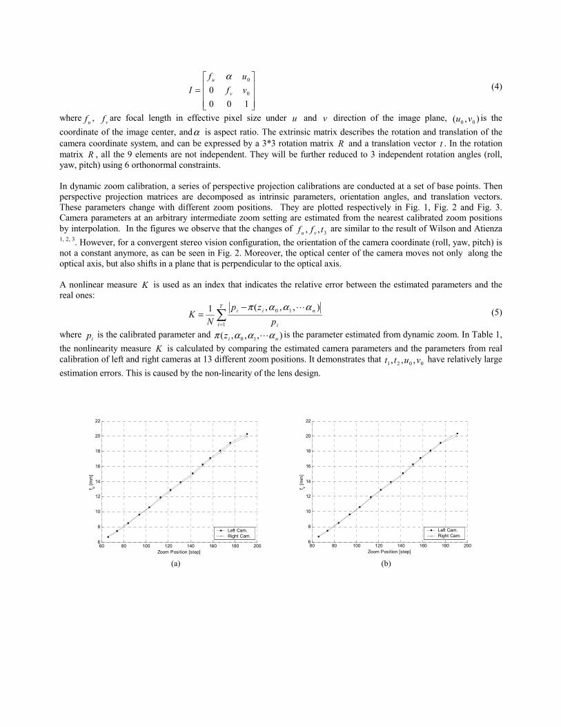
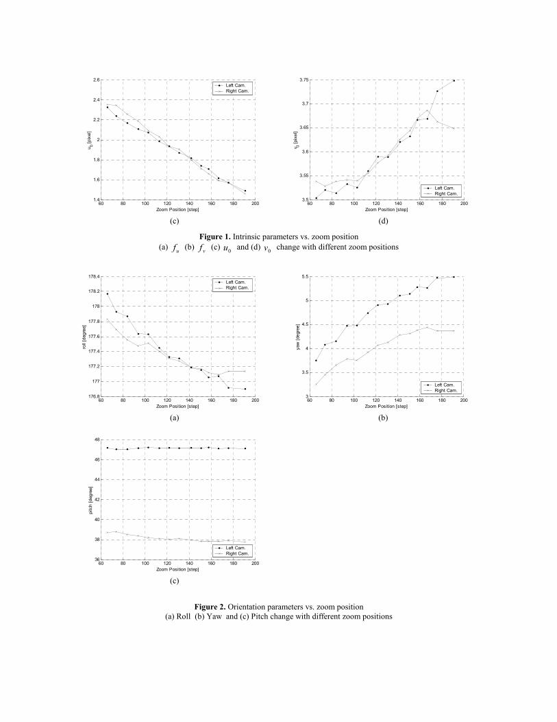
where uf , vf are focal length in effective pixel size under u and v direction of the image plane, ),( 00 vu is the coordinate of the image center, andα is aspect ratio. The extrinsic matrix describes the rotation and translation of the camera coordinate system, and can be expressed by a 3*3 rotation matrix R and a translation vector t . In the rotation matrix R , all the 9 elements are not independent. They will be further reduced to 3 independent rotation angles (roll, yaw, pitch) using 6 orthonormal constraints. In dynamic zoom calibration, a series of perspective projection calibrations are conducted at a set of base points. Then perspective projection matrices are decomposed as intrinsic parameters, orientation angles, and translation vectors. These parameters change with different zoom positions. They are plotted respectively in Fig. 1, Fig. 2 and Fig. 3. Camera parameters at an arbitrary intermediate zoom setting are estimated from the nearest calibrated zoom positions by interpolation. In the figures we observe that the changes of 3,, tff vu are similar to the result of Wilson and Atienza 1, 2, 3. However, for a convergent stereo vision configuration, the orientation of the camera coordinate (roll, yaw, pitch) is not a constant anymore, as can be seen in Fig. 2. Moreover, the optical center of the camera moves not only along the optical axis, but also shifts in a plane that is perpendicular to the optical axis. A nonlinear measure K is used as an index that indicates the relative error between the estimated parameters and the real ones:
∑=
−=
T
i i
nii
pzp
NK
1
10 ),,,(1 αααπ m (5)
where ip is the calibrated parameter and ),,,( 10 niz αααπ m is the parameter estimated from dynamic zoom. In Table 1, the nonlinearity measure K is calculated by comparing the estimated camera parameters and the parameters from real calibration of left and right cameras at 13 different zoom positions. It demonstrates that 0021 ,,, vutt have relatively large estimation errors. This is caused by the non-linearity of the lens design.
60 80 100 120 140 160 180 2006
8
10
12
14
16
18
20
22
Zoom Position [step]
f u [mm
]
Left Cam.Right Cam.
60 80 100 120 140 160 180 200
6
8
10
12
14
16
18
20
22
Zoom Position [step]
f v [mm
]
Left Cam.Right Cam.
(a) (b)
60 80 100 120 140 160 180 2001.4
1.6
1.8
2
2.2
2.4
2.6
Zoom Position [step]
u 0 [pix
el]
Left Cam.Right Cam.
60 80 100 120 140 160 180 200
3.5
3.55
3.6
3.65
3.7
3.75
Zoom Position [step]
v 0 [pix
el]
Left Cam.Right Cam.
(c) (d)
Figure 1. Intrinsic parameters vs. zoom position (a) uf (b) vf (c) 0u and (d) 0v change with different zoom positions
60 80 100 120 140 160 180 200176.8
177
177.2
177.4
177.6
177.8
178
178.2
178.4
Zoom Position [step]
roll
[deg
ree]
Left Cam.Right Cam.
60 80 100 120 140 160 180 200
3
3.5
4
4.5
5
5.5
Zoom Position [step]
yaw
[deg
ree]
Left Cam.Right Cam.
(a) (b)
60 80 100 120 140 160 180 20036
38
40
42
44
46
48
Zoom Position [step]
pitc
h [d
egre
e]
Left Cam.Right Cam.
(c)
Figure 2. Orientation parameters vs. zoom position
(a) Roll (b) Yaw and (c) Pitch change with different zoom positions

60 80 100 120 140 160 180 200-52
-50
-48
-46
-44
-42
-40
Zoom Position [step]
t 1 [mm
]Left Cam.Right Cam.
60 80 100 120 140 160 180 200
46
48
50
52
54
56
58
Zoom Position [step]
t 2 [mm
]
Left Cam.Right Cam.
(a) (b)
60 80 100 120 140 160 180 200-560
-550
-540
-530
-520
-510
-500
-490
-480
Zoom Position [step]
t 3 [mm
]
Left Cam.Right Cam.
(c)
Figure 3. Translation parameters vs. zoom position
(a) 1t (b) 2t and (c) 3t change with different zoom positions
K [%] fu fv u0 v0 roll yaw pitch t1 t2 t3 Left 0.58 0.58 1.34 0.81 0.04 0.70 0.23 3.22 1.45 0.25
Right 0.50 0.50 1.13 0.78 0.02 0.84 0.16 1.53 0.90 0.18
Table 1. Non-linear measure K for different parameters Zoom setting ranges from step number 70 to 190 at intervals of 10 steps, N = 13
4. RECTIFICATION
While matching stereo images, rectification is used to reduce computation and the possibility of mismatching. Rectification based on PPM is briefly introduced here 4. In order to have horizontal epipolar lines, the baseline must be parallel to the new X axis of both cameras. In addition, corresponding points must have the same vertical position (Y coordinate). Consequently, the position of new optical centers is the same as that in the old ones after suitable rotations, and intrinsic parameters are the same for both cameras. Therefore, the new projection matrices will differ only in their optical centers. Let us write the new PPMs in terms of their QR factorization:
][][
22
11
RcRIPRcRIP
n
n
−=−= (6)
The intrinsic parameter matrix I is same for both new projective matrices. The rotation matrix R is the same for both PPMs. To rectify the left image and the right image, we need to compute a transformation mapping of the image plane
]|[ 010101 qQP = onto the image plane ]|[ 111 nnn qQP = . We will see that the sought transformation is the collinearity
given by 3*3 matrix 1111
−= on QQT . The same result applies to the right image. For any 3D point w , we can connect it to a corresponding point m on the image plane by a PPM P . Thus for the same 3D point w , there are two points on the image plane that correspond to before and after rectification respectively.
wPmwPm
nn
oo
11
11
== (7)
Then the optical rays that connect image points 1om , 1nm , and the optical center are described in parametric form as:
RmQcwRmQcw
nnnn
oo
∈+=∈+=
−
−
λλλλ
11
11
011
101 (8)
From Eqs. (8), we have: RmQQm oonn ∈= − λλ 1
1111 (9)
where λ is an arbitrary scale factor. Reconstruction of 3D points by triangulation can be performed from the rectified image directly, using 21 , nn PP .
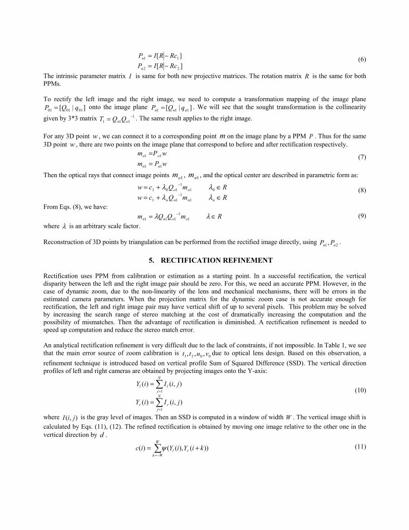
5. RECTIFICATION REFINEMENT Rectification uses PPM from calibration or estimation as a starting point. In a successful rectification, the vertical disparity between the left and the right image pair should be zero. For this, we need an accurate PPM. However, in the case of dynamic zoom, due to the non-linearity of the lens and mechanical mechanisms, there will be errors in the estimated camera parameters. When the projection matrix for the dynamic zoom case is not accurate enough for rectification, the left and right image pair may have vertical shift of up to several pixels. This problem may be solved by increasing the search range of stereo matching at the cost of dramatically increasing the computation and the possibility of mismatches. Then the advantage of rectification is diminished. A rectification refinement is needed to speed up computation and reduce the stereo match error. An analytical rectification refinement is very difficult due to the lack of constraints, if not impossible. In Table 1, we see that the main error source of zoom calibration is 0021 ,,, vutt due to optical lens design. Based on this observation, a refinement technique is introduced based on vertical profile Sum of Squared Difference (SSD). The vertical direction profiles of left and right cameras are obtained by projecting images onto the Y-axis:
∑
∑
=
=
=
=
N
jrr
N
jll
jiIiY
jiIiY
1
1
),()(
),()( (10)
where ),( jiI is the gray level of images. Then an SSD is computed in a window of width W . The vertical image shift is calculated by Eqs. (11), (12). The refined rectification is obtained by moving one image relative to the other one in the vertical direction by d .
∑−=
+=W
Wkrl kiYiYic ))(),(()( ψ (11)

[ ])(min icd = (12) Fig. 4 (a) and (b) show images of a toy dog recorded by the left and the right cameras. The size of images is 960*1280 pixels. Their normalized vertical profile is plotted in Fig. 4(c). The vertical line difference from Y-SSD is shown in Fig. 4(d). The width of the SSD window is 180 pixels. There are three areas. Area 1 and Area 3 are noise-dominated due to non-uniform illumination. Area 2 is object-dominated, and the vertical line difference is a constant (5 lines). The partial shapes before and after rectification refinement are shown in Fig. 5 (a) and (b) respectively.
(a) (b)
(c) (d)
Figure 4. Rectification refinement (a) Left image (b) Right image (c) Vertical profile of left and right image (d) SSD result

Figure 5. Partial shapes before and after rectification refinement
6. MULTI-VIEW ROTATION AXIS ESTIMATION
For a complete 3D model, single partial shape from one view is not enough. A rotation stage is used in our stereo vision system to rotate the object. It is equivalent to fixing the object and rotating the stereo camera. In Fig. 6, the full 3D model are integrated from 8 partial shapes, and each partial shape is obtained from different views which range from View 1 to View 8. Since the partial shapes are referenced to different camera coordinate systems, it is necessary to register the partial shapes. Multi-view calibration describes the position and orientation of the rotation axis around which the different partial shapes are measured. The rotation axis is expressed by a turntable matrix (4*4). A multi-view calibration method that is similar to the camera perspective projection calibration has been developed. The result from multi-view calibrations can be expressed as a turntable matrix:
=
10cscs tR
T (13)
As described in Sec. 3, the optical center of cameras wobbles around the optical axis with different zoom settings. As shown in Fig. 6, the optical center of the left and right camera shift from 21,OO to nn OO 21 , with the change of zoom position. That means the turntable matrix, which describes the rotation axis with respect to the optical center, also changes. However the origin of the world coordinate is still fixed and can be used as the connection between the epipolar geometry before and after zoom change. The turntable matrix of the dynamic zoom can be calculated from a calibrated rotation matrix T , a calibrated PPM sP , and the estimated PPM zP from dynamic zoom. The new turntable matrix is obtained by:
=
10nn
n
tRT (14)
where:
cszsn RRRR )( 1−= (15)
cszsn tttt +−= )( (16) and zszs ttRR ,,, are decomposed from the calibrated PPM sP and estimated PPM zP :
][][
zzz
sss
tRIPtRIP
== (17)

Figure 6. Multi-view integration and rotation axis estimation
7. RESULTS Experiments were conducted on the Stonybrook VIsion System (SVIS-3). As shown in Fig. 7, SVIS-3 system is composed of a digital stereo camera, a rotation stage, and light sources. The digital stereo camera is made up of two vertically-mounted Olympus C-4000 digital cameras. Two checkerboard planes are mounted perpendicularly as a calibration pattern. Olympus C-4000 has 130 zoom levels that range from 65 to 195 steps. The full 3D model after multi-view calibration estimation is shown in Fig. 8. We see that the final full 3D models are quite good.
Figure 7. SVIS-3 3D modeling system
(a) (b)
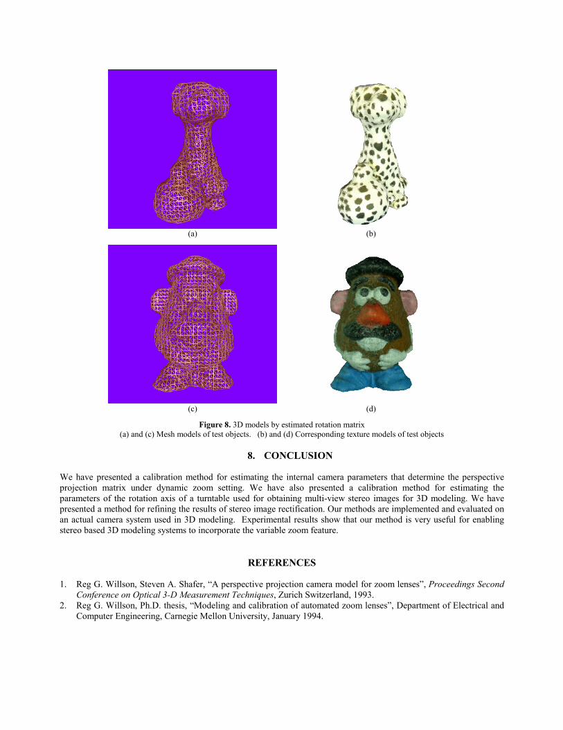
(c) (d)
Figure 8. 3D models by estimated rotation matrix (a) and (c) Mesh models of test objects. (b) and (d) Corresponding texture models of test objects
8. CONCLUSION
We have presented a calibration method for estimating the internal camera parameters that determine the perspective projection matrix under dynamic zoom setting. We have also presented a calibration method for estimating the parameters of the rotation axis of a turntable used for obtaining multi-view stereo images for 3D modeling. We have presented a method for refining the results of stereo image rectification. Our methods are implemented and evaluated on an actual camera system used in 3D modeling. Experimental results show that our method is very useful for enabling stereo based 3D modeling systems to incorporate the variable zoom feature.
REFERENCES 1. Reg G. Willson, Steven A. Shafer, “A perspective projection camera model for zoom lenses”, Proceedings Second
Conference on Optical 3-D Measurement Techniques, Zurich Switzerland, 1993. 2. Reg G. Willson, Ph.D. thesis, “Modeling and calibration of automated zoom lenses”, Department of Electrical and
Computer Engineering, Carnegie Mellon University, January 1994.

3. Rowel Atienza, Alex Zelinsky, “A practical zoom camera calibration techniques: an application of active vision for human-robot interaction”, Proceedings 4th IEEE International Conference on Multimodal Interfaces, Pittsburgh, Pennsylvania, 2002.
4. Fusiello, E. Trucco, and A. Verri., “A compact algorithm for rectification of stereo pairs”, Machine Vision and Applications, Vol. 12(1), pp. 16–22, 2000.
5. R. Y. Tsai. “A versatile camera calibration technique for high-accuracy 3D machine vision metrology using off-the-shelf TV cameras and lenses”, IEEE Journal of Robotics and Automation, RA-3(4), pp. 323–344, 1987.
6. Zhengyou Zhang, “A flexible new technique for camera calibration”, IEEE Transaction on Pattern Analysis and Machine Intelligence, Vol. 22, pp.1330-1334, 2000.
7. Emamuele Trucco, Alessandro Verri, Introductory techniques for 3-D computer vision, Prentice Hall, 1998.