Embed Size (px)
Citation preview
SMZ-161 Series Stereo Zoom Microscopes Instruction Manual

1
We are constantly endeavoring to improve our instruments and to adapt them to the requirements of
modern research techniques and testing methods. This involves modification to the mechanical
structure and optical design of our instruments.
Therefore, all descriptions and illustrations in this instruction manual, including all specifications are
subject to change without notice.
2
TABLE OF CONTENTS
Section Page
1. INTRODUCTION 3
1.1 Nomenclature 4
2. UNPACKING AND ASSEMBLING THE MICROSCOPE 5
2.1 Unpacking the Microscope 5
2.2 Assembling the Microscope 5
3. MICROSCOPE ALIGNMENT AND OPERATION 6
3.1 Interpupillary Distance 6
3.2 Focusing the Microscope 6
3.3 Magnification and Working Distance 6
3.4 Changing the Bulb 7
4. KNOWING YOUR MICROSCOPE 8
4.1 Stereo Body with Binocular or Trinocular Head 8
4.2 Stand 9
4.3 External Illuminator 9
4.4 Eyepieces and Auxiliary Objectives 10
4.5 Other Accessories 11
5. CLEANING AND CARING FOR THE MICROSCOPE 13
5.1 Protection against Dust 13
5.2 Protection against Water and Moisture 13
5.3 Cleaning 13
5.4 Moving the Microscope 14
5.5 Electrical Parts of the Microscope 14
APPENDIX 1: SMZ-161 SPECIFICATIONS 15
APPENDIX 2: SMZ-161 OPTICAL DATA 16

3
1. INTRODUCTION
The Motic SMZ-161 series stereomicroscopes are high performance Greenough design
stereomicroscopes with continuous zoom ranges of 6:1. The microscopes in this series allow
continuous variable magnification between 7.5X-45X, while total magnification varies from 2.25X to
180X depending on the eyepieces and auxiliary objectives used. With the bilateral zoom knobs, users
are able to adjust magnification while the microscope remains perfectly parfocal.
The SMZ-161 is the ideal instruments for examining objects of industrial, biological, medical or
educational natures.
SMZ-161 Standard Configuration and Parameters:
Details please refer to the Appendix 1 SMZ-161 Specifications.
Model Eyepieces Auxiliary
Objectives Zoom factor
Magnification Working Distance
Lens Tubes
SMZ-161B WF10X (Ø20)
Optional 1:6 7.5X-45X 110mm Binocular
SMZ-161T Trinocular
There are at the moment two models in the series: the SMZ-161B which is equipped with a binocular
system, and the SMZ-161T which is equipped with a trinocular system allowing for the attachment of
CCD and digital camera devices.

1.1 Nomenclature
SMZ-161-R2GG / R2LED (Fig.1)
4
SMZ-161-BP (Fig.2)
5
2. UNPACKING AND ASSEMBLING THE MICROSCOPE
2.1 Unpacking the Microscope
The components for SMZ-161 stereomicroscopes are shipped integrative for protection. Open the
Styrofoam packing with care and do not leave any components attached to the packing being removed.
Do not discard any of the packing materials until all of the components have been identified. If any
damage occurs during transit, contact both the carrier and your supplier immediately.
2.2 Assembling the Microscope
2.2.1 When handling the components, especially the optical parts, avoid touching any lens surfaces
with bare hands or fingers as fingerprints and grease stains affect image quality.
2.2.2 After unpacking the stand, put it on a stable and flat table. Loosen the locking screw of the
head holder, adjust the height of the head holder and lock the locking screw again. Make sure
that the support collar is secured firmly below the head holder along the vertical post.
This is important as this collar keeps the microscope from sliding down the column.
2.2.3 The head holder should rest on the support collar and both the head holder locking screw and
the collar locking screw should be tightened.
2.2.4 Put the stereo body onto the head holder and lock it using the locking screw located on the
right hand side of the head holder. To maintain the best stability, you are advised to lock the
screw on the left hand side of the head holder as well.
2.2.5 After removing the wrapping papers and packing materials around the eyepieces and other
optical parts (avoid touching the lens surfaces), carefully place the eyepieces into the eyepiece
tubes and secure them using the locking screws. If necessary, loosen the locking screws before
putting in the eyepieces.
2.2.6 Before turning on the power, plug the illumination power cord into the socket at the top of the
column. Next, plug the power cord of the main frame into the local power supply. Note: before
plugging in and turning on the power, make sure that the operation voltage of the
microscope matches the voltage of the local power supply.

6
3. MICROSCOPE ALIGNMENT AND OPERATION
3.1 Interpupillary Distance
Adjust the two eyepiece tubes until only one circular field can be seen through the two eyepieces. If two
separate circles appear, the interpupillary distance is too large; if two overlapping circles appear, the
interpupillary distance is too small.
3.2 Focusing the Microscope
To focus the sample, use the focusing knobs located on both sides of the head holder. By turning these
knobs, the microscope can be moved up or down a certain distance to focus the sample. This
movement is enabled by a “rack and pinion” mechanism. The tension of the focusing knob can be
adjusted using the tension knob located in the inner region of the focusing knob on the right.
If a sharp focus cannot be achieved using this knob, release the locking screw and support collar and
move the whole microscope up or down.
3.2.1 Using the focusing knob, focus the sample using the highest magnification strength. If the
sample cannot be brought into focus, adjust the height of the microscope along the column.
Remember to tighten the locking screw and support collar after adjusting the height of the
microscope.
3.2.2 Turn the zoom to the highest magnification. Adjust the focusing knob until a clear and sharp
image is obtained.
3.2.3 Turn the zoom to the lowest magnification. Adjust the right eyepiece diopter until the image
seen through the right eyepiece is clear and sharp.
3.2.4 Repeat the procedure for the left eyepiece. Next, check the image focus for the entire zoom
range; it should now be perfectly parfocal.
3.3 Magnification and Working Distance
3.3.1 Select the desired magnification strength by adjusting the zoom knob. Change the optional
eyepieces and/ or add an auxiliary objectives, for other range of magnification.
3.3.2 Total magnification used can be calculated using the following equation:
Total magnification = Eyepiece magnification X Zoom magnification X
Objective lens magnification

7
3.3.3 Working distance varies from 301mm (when using a 0.3X objective lens) to 38.6mm (when a 2X
objective lens is used). Normal working distance for standard configuration (1X objective lens) is
110mm.
3.4 Changing the Bulb
3.4.1 Before changing the light bulb, make sure that the power is switched off and the power cord has
been disconnected from the main power supply.
3.4.2 For incident light, unscrew the lamp collector piece, remove the old halogen bulb (when a
R2GG halogen stand used) or the old LED module (when a R2LED stand used) from the socket
and carefully plug the new halogen bulb or LED module in. Screw the collector piece back in
after changing the old one.
3.4.3 For transmitted light, turn the microscope over so that the bottom plate of the stand faces
towards the user. Remove the bottom plate by unscrewing the four rubber feet. For R2GG
halogen stand, remove the old light bulb from the socket and carefully plug the new light bulb in;
for R2LED stand, unscrew the plank and remove the old LED module and screw the new LED
module in place. Finally, firmly secure the bottom plate after changing the light bulb or LED
module.
3.4.4 Never touch the glass surface of the light bulb with bare hands. Any grease on the light bulb will
affect heat dissipation, greatly shortening the life span of the light bulb. If the surface of the bulb
has been accidentally touched, clean with alcohol and tissue.
8
4. KNOWING YOUR MICROSCOPE
4.1 Stereo Body with Binocular or Trinocular Head
For the SMZ-161 stereomicroscopes, the binocular or trinocular tubes are built into the stereo body to
form a single unit called a “Stereo-head”. The SMZ-161B (Fig.1) is equipped with a binocular tube
while the SMZ-161T (Fig.2) is equipped with a trinocular tube.
4.1.1 Stereo Body
● The Stereo body is the key component of the microscope. It includes the Greenough stereo-zoom
system with a continuous zoom range of 6:1. It also includes separate left and right non-telescopic
optics systems.
● With this system, users are able to enjoy excellent depth of field and stereo effects. With the help of
precision optics from Motic, perfect parfocality is maintained throughout the entire zoom range.
● The zoom knobs are located on both sides of the microscope and scales are printed on the knobs to
display the current magnification. Adjust these knobs to change the magnification of the image. If the
microscope has been properly adjusted, the image should remain in focus even when the
magnification is changed (parfocal). For adjustment procedures, refer to section 3.2 of this manual.
● The stereo body is mounted onto the circular mount of the head holder and is locked into place
using the locking screw on the right hand side of the holder. While operating the microscope, this
locking screw should always be locked to maintain utmost stability.
4.1.2 Binocular tube for the SMZ-161B
● The interpupillary distance can be adjusted by moving horizontally the two eyepiece tubes. For
proper interpupillary distance adjustment, refer to section 3.1 of this manual.
● The eyepiece can be secured in the eyepiece tube using a small screw. This is important for easy
adjustment of the eyepiece diopter.
4.1.3 Trinocular tube for the SMZ-161T
● The procedures for adjusting the interpupillary distance and securing the eyepieces are the same for
the trinocular tube as they are for the binocular tube.
● By turning the knob at the left side of the trinocular tube, all the light from the right eyepiece tube will
be deflected into the phototube for the attached imaging device.
● At the top of the trinocular tube, there is a locking screw that is used to secure the adapter for the
imaging device. After fitting the adapter, this locking screw should be tightened.

9
4.2 Stand
Three different stands are available for the SMZ-161:
4.2.1 R2GG (Fig.1)
● New stand with reflector design to reach more homogeneous illumination and lower temperature;
● The head holder can be moved freely along the vertical post and be removed totally from the stand.
The diameter of the post is 25mm.
● This stand is installed with built-in transmitted light (halogen 12V/20W) and incident light (halogen
12V/10W) illuminators.
● To turn the stand power on, the main switch (located on the left hand side) should be switched to the
on position.
● A separated power switch for transmitted and incident illumination is located on the right hand side.
Users are able to select transmitted or incident light or both with these two power switches.
● Light intensity can be adjusted by turning the knob at the bottom of the stand on the right hand side.
This knob governs the light intensity for the transmitted and incident lights.
● The illuminating angle of the incident light can be adjusted using the screw located behind the
illuminator.
● Besides the black and the white stage plate, a frosted glass stage plate is provided for transmitted
light. This plate can be secured using the screw at the bottom front of the stand.
4.2.2 R2LED (Fig.1)
● Basically the same as the “R2GG” stand except that a 3W LED is used instead of halogen bulb for
transmitted light and incident light. It delivers almost no heat to the sample and is ideal for biological
applications.
4.2.3 Plain stand (Fig.2)
● This industrial stand allows for extreme flexibility in positioning. It includes a heavy base to maintain
good stability.
4.3 External Illuminator
4.3.1 All kinds of external illuminators can be used as incident illuminators ranging from simple desk
lamps to specialized ring illuminators.
10
4.3.2 A specially designed cold light source employing a 12V/150W halogen illuminator is
recommended as a light source. Such a light source allows users to bend and twist the arm in
any direction in order to achieve the best possible illumination. As well, with a cold light source,
no heat is transmitted to the specimen making it ideal for use in biological research and
anatomy.
4.3.3 A 3W LED ring light illuminator for Motic SMZ-161 stereomicroscopes also is available.
4.4 Eyepieces and Auxiliary Objectives
4.4.1 There are eyepieces of different magnifications to choose from including 10X, 15X and 20X.
Standard configuration is a pair of 10X eyepieces.
4.4.2 To change the eyepieces, unscrew the locking screw, remove the original eyepieces, replace
with the new pair of eyepieces and secure the eyepieces using the locking screw.
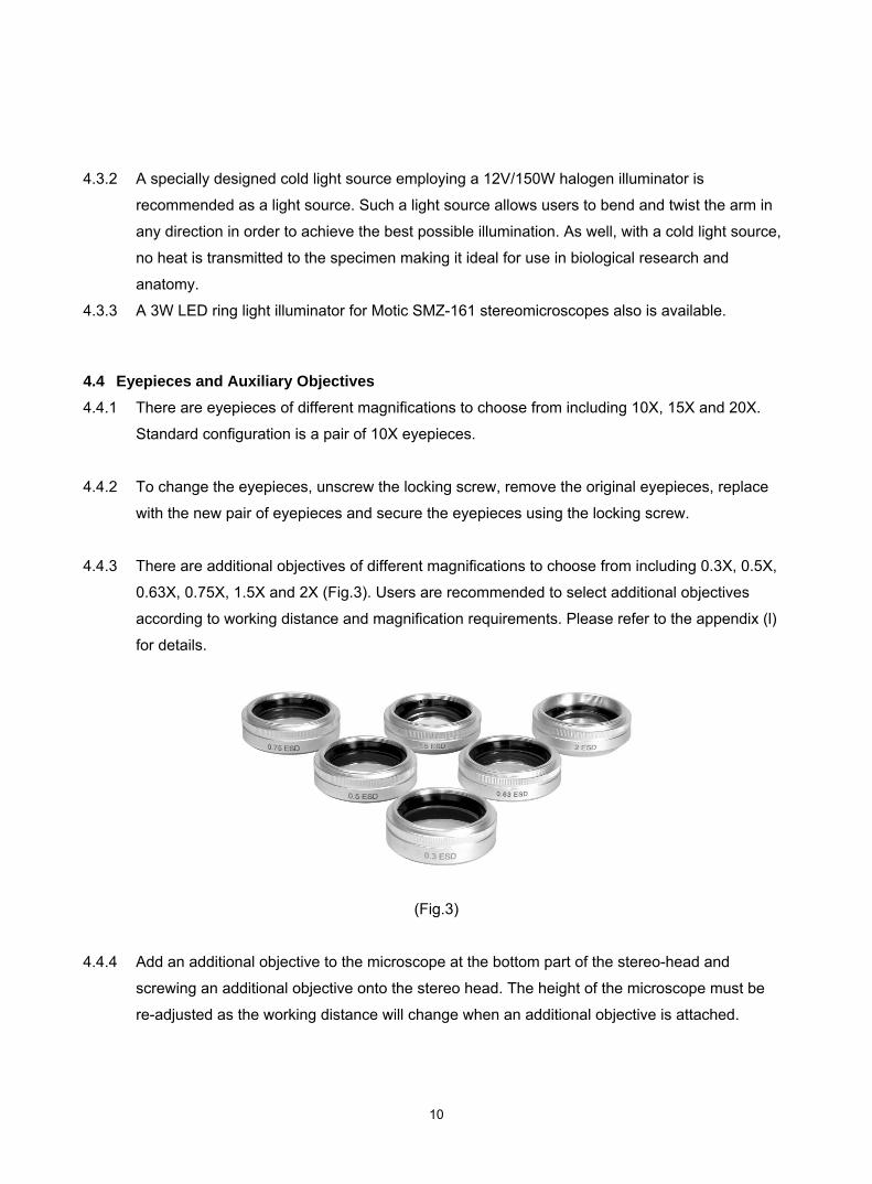
4.4.3 There are additional objectives of different magnifications to choose from including 0.3X, 0.5X,
0.63X, 0.75X, 1.5X and 2X (Fig.3). Users are recommended to select additional objectives
according to working distance and magnification requirements. Please refer to the appendix (l)
for details.
(Fig.3)
4.4.4 Add an additional objective to the microscope at the bottom part of the stereo-head and
screwing an additional objective onto the stereo head. The height of the microscope must be
re-adjusted as the working distance will change when an additional objective is attached.

11
4.5 Other Accessories
4.5.1 For the SMZ-161 there are various accessories designed for various applications:
Darkfield Condenser
● Must be used with transmitted light.
● By putting this accessory onto the transmitted light outlet (with the frosted glass or stage plate
removed) a darkfield effect is created.
● It is especially useful for analyzing jewelry and special techniques in Bio-Med applications including
“In-situ silver gain staining” and embryo observation.
Polarizing kit
● Must be used with transmitted light.
● This kit (including both a polarizer and analyzer) is also placed onto the transmitted light outlet (with
the stage plate removed). The sample can be placed between the polarizer and analyzer to perform
polarized light microscopy.
● Useful for analyzing jewelry and the study of sectioned rock and synthetic fibers.
Jewelry Clamp (Fig.4)
● Designed to hold gems or jewelry under the microscope while performing observation.
(Fig.4)

12
Photo adapter SY10
● Attaches to the top of the trinocular tube, allowing any SLR camera to be connected to the
microscope for imaging purposes.
● The SY10 adapter for the selected camera has to be screwed into the adapter before connecting to
the camera. This SY10 adapter can be obtained from any camera store in your area.
● Can only be used with the SMZ-161T.
C-mount or CS-mount
● Attaches to the top of the trinocular tube, allowing any CCD camera or imaging device to be
connected to the microscope.
Select either the C-mount or CS-mount according to the CCD camera to be used.
● Can only be used with the SMZ-161T.
Improved industrial boom stands
● With New slot / groove design for better locking microscope.
● Grub screw locks into slot / groove, stopping tilt. Microscope is positioned vertical to base with no
slant
● Add position for hand-carrying around four sides
● New modularity can be used in wide-range of our SMZ series microscope which allows observing
larger viewing samples
● Decrease tools. Now only one H3 Allen key.
● Aluminum support collar and plastic elastic gasket without nick

13
5. CLEANING AND CARING FOR THE MICROSCOPE
To keep the microscope in good working order avoid, dust and water. If any dust or water happens to
get into the microscope, fungus will grow, damaging the microscope. Please note that once fungus has
grown, even after cleaning, the problem may reoccur.
Grease stains and fingerprints affect image quality, avoid allowing fingers to come into contact with
the surface of optical components.
5.1 Protection against Dust
If the instrument is not to be used for a long period of time, cover it with the dust cover provided. Never
leave the eyepiece tube exposed. Either leave the eyepiece in the tube (recommended if the
microscope is frequently used) or cover it with wrapping paper or a covering cap. Eyepieces and other
optical components that will not be used for a relatively long period of time should be stored in a dry
cardboard box, preferably with a desiccating agent added, to shield against dust and moisture.
5.2 Protection against Water and Moisture
The instrument should be kept away from all water sources, including pipes and sinks. Humidity in the
room where the instrument located should be kept as low as possible (relative humidity should be kept
below 70%). It is recommended that optical components be kept in a dry box when not in use,
preferably with a desiccating agent added. The use of dehumidifier and/or 24-hour air conditioning is
highly recommended if the surrounding area is humid.
5.3 Cleaning
5.3.1 If dust is found on the optical surface, remove by using an air blower or compressed air.
5.3.2 For fingerprint, grease stains or dust which cannot be removed using air, two possible methods
are recommended:
● Breathe lightly on the glass surface and wipe with a clean piece of cloth, lens paper or cotton swab.
Please note that small cotton fibers may remain on the surface of the lens if a cotton swab is used.
● Use a cotton swab or lens paper dipped in a small amount of pure alcohol and clean the lens surface
carefully. No other aggressive solvents should be used.

14
Under no circumstances should users clean any lens surface with a dry cotton swab, dry
cloth or dry lens paper as this will scratch the lens surface causing irreparable damage. Water
is not recommended for cleaning lenses as it will leave water stains on the lens surface
possibly leading to fungus growth causing irreparable damage.
5.4 Moving the Microscope
5.4.1 The microscope should be moved around as little as possible.
5.4.2 If it is necessary to move the microscope, users should ensure that the eyepieces are firmly
secured in the eyepiece tubes, the microscope is firmly secured to the vertical post and the
support collar is firmly secured before moving.
5.4.3 When moving the microscope, use both hands, one hand holding the bottom of the stand and
the other hand holding the top of the vertical post of the head holder of the microscope.
5.4.4 The microscope should always be kept upright while moving.
5.5 Electrical Parts of the Microscope
5.5.1 Before plugging the power cord into the power supply, make sure that the supply voltage
matches the operation voltage of the equipment.
5.5.2 Turn the equipment off before plugging the power cord into the power supply.
5.5.3 It is recommended that users turn down the illumination before turning off the equipment.
5.5.4 Do not turn the power on again immediately after it has been turned off as this will shorten the
life span of the light bulb and may cause damage to the electrical system.
5.5.5 Users should observe all local safety regulations. While the equipment is CE safety approved,
users are expected to use the equipment in a safe and responsible manner.

15
APPENDIX 1: SMZ-161 SPECIFICATIONS
Model SMZ-161B SMZ-161T
Optical system Greenough Binocular head Observation angle
45°
Magnification rang (standard) 0.75X--4.5X
Zoom ratio 1:6
Eyepiece WF10X (Ø20) / eyepiece tube adjustable
N-WF 15X (Ø16), 20X (Ø13) for optional with RoHS lens
Interpupilary adjustment 50mm-75mm
Height of eye point 367mm
Working distance(standard) 110mm
Adapters
0.5X, 0.65X, 1X adapters available
Auxiliary ESD objectives
0.3X [WD = 301 mm] 0.5X [WD = 191.8 mm]
0.63X [WD = 142.7 mm] 0.75X [WD = 128.6 mm] 1.5X [WD = 56.3 mm ] 2.0X [WD = 38.6 mm]
Max. working distance 301mm
Weight 3.5kg (head with 1.0kg) 3.7kg (head with 1.2kg)
Optional illuminator Ring LED light / fluorescent ring illuminator / cold light source
Stand option
● Plain stand ● Compact R2LED stand with 3W LED ● Compact R2GG stand with 12/10W halogen incident and 12/20W halogen transmitted light ● Optionally several boom stands for industrial use are available

16
NO.: 1300901108871
Motic Incorporation Ltd. (Hong Kong)Rm 2907-8, Windsor House, 311 Gloucester Road, Causeway Bay, Hong Kong Tel: 852-2837 0888 Fax: 852-2882 2792
Motic Instruments Inc. (Canada)130-4611 Viking Way, Richmond, B.C., V6V 2K9 Canada Tel: 1-877-977 4717 Fax: 1-604-303 9043
Motic Deutschland GmbH (Germany)Christian-Kremp-Strasse 11 D-35578 Wetzlar, Germany Tel: 49-6441-210 010 Fax: 49-6441-210 0122
Motic Spain, S.L. (Spain)Polígon Industrial Les Corts, Camí del Mig, 112 08349 Cabrera de Mar, Barcelona Spain Tel: 34-93-756 6286 Fax: 34-93-756 6287
Website: http://www.motic.comE-mail: [email protected]
Motic China Group., Ltd. (China)Motic Building, Torch Hi-Tech Industrial, Development Zone, Xiamen P.R.C. Tel: 86-0592-562 7866 Fax: 86-0592-562 7855
© 2000-2012 Motic China Group Co., Ltd. All rights reserved. Motic is a registered trademark and service mark of Motic China Group Co., Ltd. Microsoft Windows logo is a registered trademark of Microsoft Corporation. All other trademarks are the property of their respective owners.
Design Change: The manufacturer reserves the right to make changes in instrument design in accordance with scientific and mechanical progress, without notice and without obligation.
Updated: June, 2012


![Gradiente SMZ 140C[1]](https://img.pdfslide.us/doc/110x75/5520f19b497959892f8b50e5/gradiente-smz-140c1.jpg)