Embed Size (px)
Citation preview

NEW DESIGN APPROACH FOR WOOD BRITTLE FAILURE
MECHANISMS IN TIMBER CONNECTIONS
ABSTRACT: Timber construction has experienced considerable progress in recent years. In such progress,
apart from the implementation of new engineered timber products, the advancement of timber joints has played
a significant role. The design procedures for timber connections in most design codes are based mainly on the
yielding capacity of the fasteners using the European Yield Model (EYM). While the EYM theory provides
accurate predictions for connections that fail in a ductile fashion, it does not take into account the failure of the
connections due to the brittle rupture of wood as the consequence of fasteners group effect. Such a significant
gap in the design of connections also applies to the New Zealand (NZS 3603) and Australian (AS 1720.1) timber
design standards. A new design approach is presented which allows the practitioners to predict the connection
capacity associated with different brittle wood failure mechanisms. An extensive testing regime has been
conducted on high load-transfer capacity joints using timber rivets under longitudinal and transverse loadings
on New Zealand Radiata Pine laminated veneer lumber (LVL) and glulam. The results verify the proposal and
prove its reliability. A design guide was also developed which could eventually become a design clause in the
next revision of the New Zealand timber design standard NZS 3603.
KEYWORDS: Connection, wood capacity, fastener capacity, timber rivet, failure mode, LVL, glulam
1 INTRODUCTION 1.1 GENERAL
Timber construction has experienced considerable
progress in recent years. In such progress, apart
from the implementation of new engineered timber
products, the advancement of timber joints has
played a significant role. Structures are detailed
from a combination of hinged and moment
resisting joints. Therefore, connections are often
the most critical components of any type of
structure. Evaluation of timber buildings damaged
after extreme wind and earthquake events have
shown that weak connections (Figure 1) are one of
the major causes of problems [1].
Figure 1: Connection brittle failure at Siemens Arena, Ballerup, Denmark
1 Pouyan Zarnani, Postdoctoral Fellow in Structural
Timber Engineering, Department of Civil and
Environmental Eng., University of Auckland.
Email: [email protected] 2 Pierre Quenneville, Professor of Timber Design,
Department of Civil and Environmental Eng., University
of Auckland. Email: [email protected]
1.2 BACKGROUND
The design procedures for timber connections in
most design codes are based mainly on the yielding
capacity of the fasteners (Figure 2) using the
European Yield Model (EYM). While the EYM
theory [2] provides accurate predictions for
connections that fail in ductile fashion, it does not
take into account the failure of the connections due
to the brittle rupture of wood as the consequence of
fasteners group effect. Such a significant gap in the
design of connections also applies to the New
Zealand NZS 3603 [3] and Australian AS 1720.1
[4] timber design standards.
Figure 2: Fastener failure modes in single shear for timber connections (involving fastener bending and/or member bearing)
Based on the state-of-the-art of wood strength
prediction models for parallel-to-grain failure in
connections using dowel-type fasteners, different
methods consider the minimum, maximum or the
summation of the tensile and shear capacities of the
failed wood block planes. This results in
disagreements between the experimental values and
the predictions. It is postulated that these methods
are not appropriate since the stiffness in the wood
blocks adjacent to the tensile and shear planes
differs and this difference leads to uneven load
distribution amongst the resisting planes [5,6]. For
instance, in a block tear-out failure (Figure 3), the
Pouyan Zarnani1, Pierre Quenneville2

contribution of the bottom or lateral shear planes to
the wood resistance cannot simply be considered as
a function of their respective area as the connection
load is not shared uniformly among the resisting
planes due to the unequal stiffness of the adjacent
wood volumes loading the fasteners.
Figure 3: Wood block tear-out failure in two joints with identical shear and tensile resisting planes and different bottom and edge distances
In the case of perpendicular-to-grain loading, the
available models for the prediction of the splitting
failure of dowel-type connections are determined
generally based on a crack growth of the entire
member cross-section. These models can be
appropriate for stocky or rigid fasteners installed
through the full thickness of the wood member.
However, for slender dowel-type fasteners such as
timber rivets, particularly when the penetration
depth of the fastener does not cover the whole
member thickness, partial splitting combined with
rolling shear can happen rather than splitting of the
entire width (Figure 4).
Figure 4: Cross-section view of wood splitting perpendicular-to-grain: (a) full width failure mode, (b) partial width failure mode
2 NEW DESIGN APPROACH 2.1 WOOD BLOCK TEAR-OUT
RESISTANCE PARALLEL-TO-GRAIN
The wood block tear-out resistance under parallel-
to-grain loading is predicted using the stiffness-
based model proposed by Zarnani and Quenneville
[7]. The proposed analysis for wood strength is best
explained using the analogy of a linear elastic
spring system in which the applied load transfers
from the wood member to the failure planes in
conformity with the relative stiffness ratio of each
resisting volume adjacent to the individual failure
plane (Figure 5).
Figure 5: Proposed spring model assuming linear elasticity
The difference in the loads channelled to the tensile
and shear planes is a function of the modulus of
elasticity (E) and modulus of rigidity (G), the
volume of wood surrounding each of the failure
planes (bottom, end and edge distances - dz, da and
de) and also of the connection geometry (Figure 6).
For details regarding the determination of the
stiffness of the resisting planes, refer to Zarnani
and Quenneville [7].
Figure 6: Simplified analytical model
By predicting the stiffness of the wood surrounding
each of the failure planes (Kh, Kb and Kl), one can
predict the proportion of the total connection load
applied to each plane, KKR ii . By further
establishing the resistance of each of the failure
planes as a function of a strength criterion, one can
verify which of the failure planes governs the
resistance of the entire connection due to being
overloaded.
It should be asserted that the strength of the shear
planes cannot be higher than the tensile capacity of
the adjacent wood volume where the load is
channelled to these resisting planes. If the attracted
load by the resisting shear planes is larger than the
tensile capacity of the associated wood volume,
then the wood block torn out from the member
would be as wide as or as deep as the member.
Therefore, as shown in Figure 7, three different
failure modes are possible and the wood load
carrying capacity of the connection (Equation 1)
equals the minimum of the resistances
corresponding to these failure modes, Pw,a, Pw,b and
Pw,c.

Figure 7: Different possible failure modes of wood block tear-out
Pw = np . min (Pw,a, Pw,b, Pw,c) (1)
where
Pw,a = min (pwh, pwb, pwl) , Mode (a)
Pw,b = min (pwh, pwb) , Mode (b)
Pw,c = min (pwh, pwl) , Mode (c)
in which
pwh = wood resistance for failure
of head tensile plane
(2)
pwb = wood resistance for failure
of bottom shear plane
(3)
pwl = wood resistance for failure
of lateral shear planes
(4)
Due to the absence of the lateral and bottom shear
planes in the failure mode (b) and (c) respectively,
the following considerations are necessary for the
resistance calculation of these failure modes:
I. For failure mode (b), the Kl/Kh and Kl/Kb ratios
should be considered as zero; and the tensile
and shear areas as wide as the member.
II. For failure mode (c), the Kb/Kh and Kb/Kl ratios
should be considered as zero; and the tensile
and shear areas as deep as the member (in the
case of double-sided joint, half of the depth
should be considered).
In Equations (2) to (4), ft,m and fv,m are the wood
mean strength in tension and in shear along the
grain (MPa). Ath, Asb and Asl are the areas of the
head, bottom and lateral resisting planes with
respect to the wood effective thickness, tef,
subjected to tension and shear stresses. Also, Cab
and Cal are the ratios of the average to maximum
stresses on the bottom and lateral shear planes
respectively [7]. np is the number of the plates
equal to 1 or 2 for one-sided or double-sided joints,
respectively.
It is also important to note that the connection
resistance corresponding to each failure mode is a
summation of the critical plane failure load, plus
the load carried by the other planes. Thus, when
one plane fails, then the entire connection load
transfers to the remaining planes in accordance
with their relative stiffness ratios. It could be
possible that the occurrence of the first failure of
one plane does not correspond with the maximum
load of the connection. Therefore, it is
recommended that after the failure of one plane,
one recalculates the wood resistance for the
remaining planes to verify whether the residual
planes can resist a higher load by defining: Kh/Kb
and Kh/Kl = 0 after the head tensile plane failure;
Kb/Kh and Kb/Kl = 0 after the bottom shear plane
failure; and Kl/Kh and Kl/Kb = 0 after the lateral
shear planes failure.
In the case of fasteners which are inserted into
predrilled holes, the area corresponding to the
cutting diameter is to be subtracted from the
resisting plane surfaces. This affects the strength of
the tensile and shear resisting planes and not their
stiffnesses.
2.2 WOOD SPLITTING RESISTANCE
PERPENDICULAR-TO-GRAIN
The wood splitting strength in perpendicular-to-
grain loading is predicted using the model proposed
by Zarnani and Quenneville [8]. The proposed
approach is based on two different possible crack
formations on the member cross-section: with
partial splitting on each side of the member
corresponding to the effective embedment depth, tef
(Figure 4b) or with full width splitting (Figure 4a).
In fact, for connections with a large penetration
depth in slender members, the governing failure
mode will be the full width splitting, and as the
ratio of member thickness to penetration depth
increases, the transition of wood failure mode from
full to partial width splitting will occur (Figure 8).
Figure 8: Occurrence zone of possible failure modes of wood splitting
Therefore, the ultimate splitting resistance of the
connection is determined as the minimum strength
corresponding to these two failure modes and is
given by Equation (5):
1 b l
t ,m th
h h
K Kf A ( )
K K
1 h l
v ,m ab sb
b b
K Kf C A ( )
K K
1 h b
v,m al sl
l l
K Kf C A ( )
K K

Pw = min (Ps,tef, Ps,b) (5)
The wood capacity for partial width splitting, Ps,tef,
is predicted using a stress-based analysis (Equation
6) and involves the perpendicular-to-grain tensile
capacity of the splitting surface of the wood
corresponding to the effective embedment depth, tef
and the crack length that propagates along the
member. The crack length along the member is
considered as the summation of the joint net section
width, wnet, and the symmetrical crack growth on
the left and right sides of the joint as a factor of the
effective depth, he (Figure 9).
Figure 9: Effective crack length on either side of the joint
In Equation (6), ftp is the tensile strength
perpendicular-to-grain; da,L and da,R are the
unloaded end distance on the left and right side of
the joint, respectively; Ct is a coefficient function of
the unloaded edge distance and the connection
length.
Ps,tef =npCtftptef [wnet+min(βhe,da,L)+min(βhe,da,R)]
(6)
The predictive equation presented for wood
splitting in the entire member cross-section, Ps,b
(Eq. (7)) is adopted from the fracture mechanics
based model developed by Van der Put and Leijten
[9]. The significant difference is the application of
the η factor which accounts for the effect of
unloaded end distance and the connection width.
(7)
in which,
and Cfp is the fracture parameter. For more details
regarding the wood splitting model, refer to
Zarnani and Quenneville [8].
3 EXPERIMENTAL PROGRAM As demonstrated over numerous studies, small-
diameter fasteners have shown a significant
advantage over large-diameter ones such as bolts
which cause large localized stresses and force
brittle ruptures in the timber. Of this family of
fasteners, the timber rivet is a well-established
example in timber connection technology [10].
Timber rivets are hardened nails with a rectangular
cross section of 3.2 by 6.4 mm. They are available
in three standard lengths; 40, 65 or 90 mm (Figure
10). Timber rivets are always driven with the long
axis parallel to the wood grain. Rivets are tight-fit
fasteners since the head is wedged into the steel
plate hole. Timber rivets provide high load-transfer
capacity, high stiffness and easy to install steel-
timber connections [11]. Rivets are part of the
Canadian CSA-O86 [12] and American NDS [13]
wood standards. However, there is no closed-form
solution for the strength prediction of this type of
connection. Therefore, timber rivets were used in
the current joint failure tests to verify the model.
Figure 10: Timber Rivet
3.1 TEST SETUP
Laboratory tests were set up to prompt wood
failures and maximize the amount of observations
on the brittle mechanism by considering higher
capacity for the fasteners compared to the wood.
Specimens were manufactured from New Zealand
Radiata Pine LVL grade 11 and GL8 grade glulam.
An extensive testing regime was conducted
including 32 test groups under parallel-to-grain
loading and 24 test groups under perpendicular-to-
grain loading. 3 replicates were tested for each
group of specimens for LVL and 4 replicates for
glulam. The specimens had riveted plates on both
faces of timber, resulting in a symmetric
connection. The steel side plates were 8.4 mm thick
of 300 grade (Fy = 300 MPa) with predrilled 6.8
mm holes to ensure adequate fixity of the rivet
head. The effect of geometry parameters such as
connection width and length, fastener penetration
depth, loaded and unloaded edge distances, end
distance, and member thickness were evaluated.
For more details regarding the connection
configurations, refer to Zarnani and Quenneville
[8,14].
The testing protocol outlined in ISO 6891 [15] was
followed. The tension load was applied to the
specimens using a displacement controlled loading
system. The deformation of the connection was
, 2
1
es b fp
e
hP bC
h
h
, ,min( , ) min( , )
2
e a L e a R net
e
h d h d w
h
L=40 mm
L=65 mm
L=90 mm

measured continously with a pair of symmetrically
placed linear variable differential transformers
(LVDT). The loading rate was adjusted to 1
mm/min and kept constant until the occurence of
failure in both or either side of the riveted
connections. A typical specimen in the testing
frame is shown in Figure 11.
Figure 11: Typical specimens in testing apparatus: (a) longitudinal loading, (b) transverse loading - mid-span, (c) transverse loading - end of member
3.2 MATERIAL PROPERTIES
All specimens were conditioned to 20°C and 65%
relative humidity to attain a target 12% equilibrium
moisture condition (EMC). The wood had an
average density of 605 and 465 kg/m3 for LVL and
glulam members respectively. For the connection
capacity parallel-to-grain, the average tensile and
shear strengths evaluated were 34.3 MPa
(coefficient of variation (COV)=12%) and 6.8 MPa
(COV=10%) for RP-LVL and 24.1 MPa
(COV=24%) and 4.2 MPa (COV=15%) for RP-
glulam (samples from inner laminations)
respectively [14]. For the stiffness properties, based
on data available in the literature, an average ratio
of modulus of rigidity to modulus of elasticity
(G/E) is considered equal to 0.045 and 0.069 for
LVL and glulam respectively in order to make the
planes’ stiffness equations independent of G and E
values. The fracture parameter value, Cfp, reported
in Jensen et al. [16] and tensile strength
perpendicular-to-grain values, ftp, evaluated by
Song [17] were used in the proposed splitting
model. The average Cfp and ftp were 22.7 N/mm1.5
and 2.06 MPa (for the tangential direction with a
COV=18%) for RP LVL and 18.4 N/mm1.5
and
1.99 MPa (at 45° to the radial direction with a
COV=24%) for RP glulam.
3.3 TEST OBSERVATIONS
Test series with a tightly spaced rivet pattern
exhibited a brittle/mixed failure mode. For parallel-
to-grain loading, a sudden failure happened where a
block of wood bounded by the rivet group
perimeter was pulled away from either one side or
both sides of the specimens (Figure 12a). As shown
in Figure 12b, in brittle failure mode, the failed
block thickness, tblock corresponds to the elastic
deformation of the rivets (tef,e) since no plastic
deflection was observed. However, in the mixed
failure mode (Figure 12c), the tblock is significantly
lower with observable small deformation of the
rivets. In the mixed failure mode cases, the load-
carrying capacity of the wood is based on the
stiffness and strength of the tensile and shear planes
corresponding to the bearing length of the fastener
(tef,y) depending on its yielding mode.
Figure 12: Wood failure parallel-to-grain: (a) block tear-out bounded by the rivet cluster perimeter, (b) brittle failure - rivets within the elastic range, (c) mixed failure - rivets with small deformation
For the tests subjected to a perpendicular-to-grain
loading, splitting of the wood occurred along the
row of rivets next to the unloaded edge and
propagated towards the timber member ends until
reaching the unstable zone (Figure 13a). The
splitting crack formed either through the entire
member width (for thin members with high
penetration-to-thickness ratios), as shown in Figure
13b or with a depth similar to the rivet effective
embedment depth (for thick members with low
penetration-to- thickness ratios), as shown in
Figure 13c.
Figure 13: Wood failure perpendicular-to-grain: (a) crack propagation along the top row of rivets, (b) full width splitting, (c) partial width splitting
4 VERIFICATION OF PROPOSED
DESIGN APPROACH 4.1 RIVETED JOINT SUBJECTED TO
PARALLEL-TO-GRAIN LOADING
The connection ultimate capacities were calculated
using the proposed stiffness-based model. For the
brittle failure mode, the elastic deformation of the
rivet was considered to determine the tef,e [7]. The
estimated tef,e was 27.1, 45.5 and 58.9 mm for a
rivet penetration (Lp) equal to 28.5, 53.5 and 78.5
mm correspondingly. In the case of mixed failure,
the tef,y was predicted based on the bearing length
corresponding to the governing yielding mode of
the rivets equal to 28.4, 40.4 and 24.7 mm for the
different penetration lengths. The tef,y value for the
longer rivet is lower compared to the other ones.
This is due to the formation of the two plastic
hinges (see Figure 2f) for this length of rivet during
the yielding failure, whereas for the smaller rivet
sizes, there is one plastic hinge (see Figure 2d).
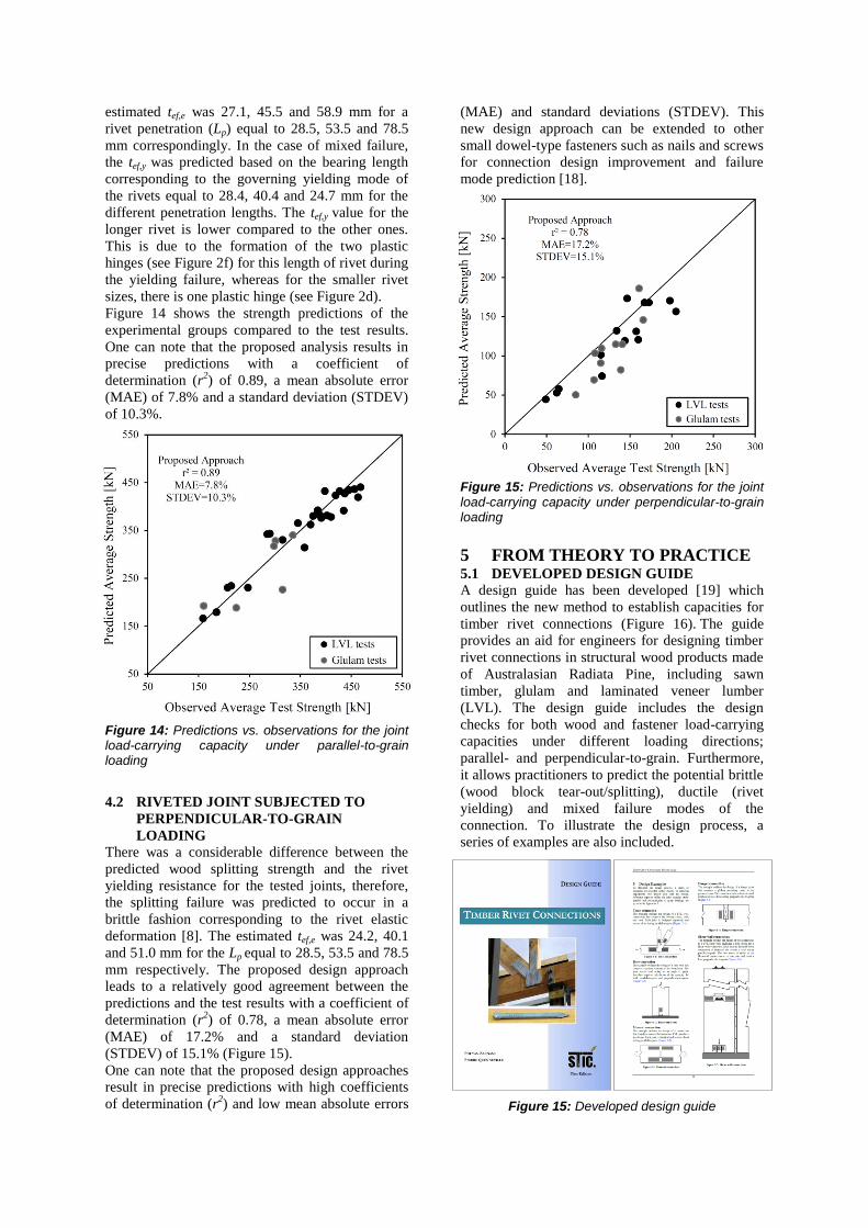
Figure 14 shows the strength predictions of the
experimental groups compared to the test results.
One can note that the proposed analysis results in
precise predictions with a coefficient of
determination (r2) of 0.89, a mean absolute error
(MAE) of 7.8% and a standard deviation (STDEV)
of 10.3%.
Figure 14: Predictions vs. observations for the joint load-carrying capacity under parallel-to-grain loading
4.2 RIVETED JOINT SUBJECTED TO
PERPENDICULAR-TO-GRAIN
LOADING
There was a considerable difference between the
predicted wood splitting strength and the rivet
yielding resistance for the tested joints, therefore,
the splitting failure was predicted to occur in a
brittle fashion corresponding to the rivet elastic
deformation [8]. The estimated tef,e was 24.2, 40.1
and 51.0 mm for the Lp equal to 28.5, 53.5 and 78.5
mm respectively. The proposed design approach
leads to a relatively good agreement between the
predictions and the test results with a coefficient of
determination (r2) of 0.78, a mean absolute error
(MAE) of 17.2% and a standard deviation
(STDEV) of 15.1% (Figure 15).
One can note that the proposed design approaches
result in precise predictions with high coefficients
of determination (r2) and low mean absolute errors
(MAE) and standard deviations (STDEV). This
new design approach can be extended to other
small dowel-type fasteners such as nails and screws
for connection design improvement and failure
mode prediction [18].
Figure 15: Predictions vs. observations for the joint load-carrying capacity under perpendicular-to-grain loading
5 FROM THEORY TO PRACTICE 5.1 DEVELOPED DESIGN GUIDE
A design guide has been developed [19] which
outlines the new method to establish capacities for
timber rivet connections (Figure 16). The guide
provides an aid for engineers for designing timber
rivet connections in structural wood products made
of Australasian Radiata Pine, including sawn
timber, glulam and laminated veneer lumber
(LVL). The design guide includes the design
checks for both wood and fastener load-carrying
capacities under different loading directions;
parallel- and perpendicular-to-grain. Furthermore,
it allows practitioners to predict the potential brittle
(wood block tear-out/splitting), ductile (rivet
yielding) and mixed failure modes of the
connection. To illustrate the design process, a
series of examples are also included.
Figure 15: Developed design guide
The guide is accessible through EXPAN (formerly
STIC) administered by the Engineered Wood
Products Association of Australasia (EWPAA).
5.2 CASE STUDIES
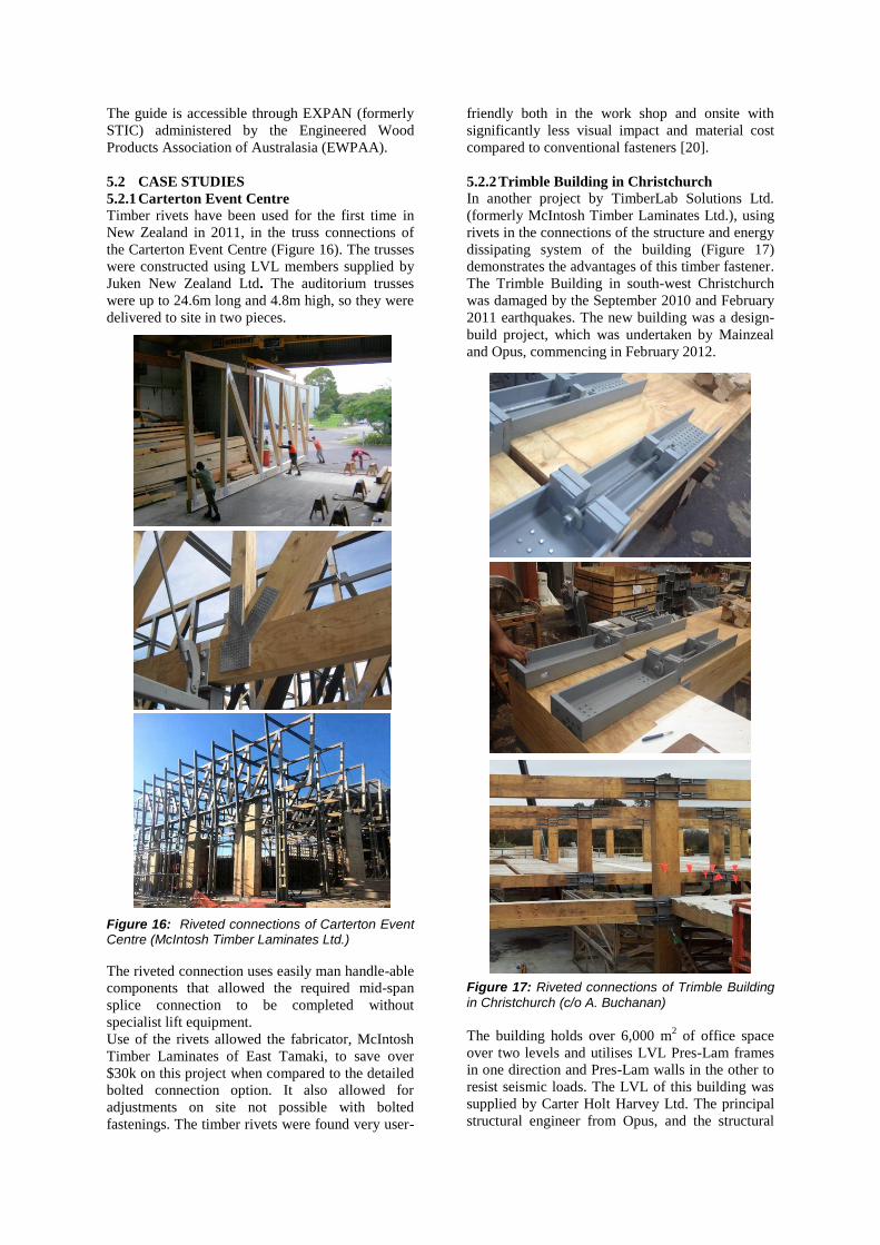
5.2.1 Carterton Event Centre
Timber rivets have been used for the first time in
New Zealand in 2011, in the truss connections of
the Carterton Event Centre (Figure 16). The trusses
were constructed using LVL members supplied by
Juken New Zealand Ltd. The auditorium trusses
were up to 24.6m long and 4.8m high, so they were
delivered to site in two pieces.
Figure 16: Riveted connections of Carterton Event Centre (McIntosh Timber Laminates Ltd.)
The riveted connection uses easily man handle-able
components that allowed the required mid-span
splice connection to be completed without
specialist lift equipment.
Use of the rivets allowed the fabricator, McIntosh
Timber Laminates of East Tamaki, to save over
$30k on this project when compared to the detailed
bolted connection option. It also allowed for
adjustments on site not possible with bolted
fastenings. The timber rivets were found very user-
friendly both in the work shop and onsite with
significantly less visual impact and material cost
compared to conventional fasteners [20].
5.2.2 Trimble Building in Christchurch
In another project by TimberLab Solutions Ltd.
(formerly McIntosh Timber Laminates Ltd.), using
rivets in the connections of the structure and energy
dissipating system of the building (Figure 17)
demonstrates the advantages of this timber fastener.
The Trimble Building in south-west Christchurch
was damaged by the September 2010 and February
2011 earthquakes. The new building was a design-
build project, which was undertaken by Mainzeal
and Opus, commencing in February 2012.
Figure 17: Riveted connections of Trimble Building in Christchurch (c/o A. Buchanan)
The building holds over 6,000 m2 of office space
over two levels and utilises LVL Pres-Lam frames
in one direction and Pres-Lam walls in the other to
resist seismic loads. The LVL of this building was
supplied by Carter Holt Harvey Ltd. The principal
structural engineer from Opus, and the structural

design team leader for the Trimble project found
that the compact timber rivets provide high strength
and stiff connections to take significant seismic
loads [21].
5.2.3 Portal frame for URM Building seismic
retrofit
In this recent project, EQStruc Ltd implemented
efficiently LVL timber portal frames to resist
seismic loads for an unreinforced masonry structure
about 45m long by 12m wide (Figure 18). To
provide strong and stiff joints between the timber
elements, rivet connections were designed with
controlled deflections. The client, a first-time user
of timber portal frames in an unreinforced masonry
(URM) building seismic retrofit, found that the
rivet connections offered a cost-effective solution.
Figure 18: Riveted connections of portal frames for URM building seismic retrofit (EQStruc Ltd.)
5.2.4 Kaikoura District Council Building
Recently, Innovations Nelson Ltd. used timber
rivets in the hold-down connections of the CLT
shear walls of the Kaikoura event centre (Figure
19). Elastic deformation of the rivet connections
were limited to 0.5 mm to satisfy the targeted
system ductility only through the extension of the
energy dissipaters under earthquake events.
Innovations Nelson Ltd. is working on another
similar project related to a 2-story commercial
building in which rivets will be applied to provide
high capacity and high stiffness hold-down
connections.
Figure 19: Riveted connections of CLT shear walls (Innovations Nelson Ltd.)
6 CONCLUSIONS Through the emergence of advanced engineered
timber products as reliable structural alternatives
along with scientific developments in timber
engineering, many international building standards
are revising their codes to accept high-rise timber
buildings. In such heavy structures where the joints
need to transfer large loads either parallel- or
perpendicular-to-grain, the brittle group failure of
the joint is more susceptible. The design procedures
for timber connections in most design codes are
based mainly on the European Yield Model which
is only applicable for the ductile failure of the
connections but not the brittle failure modes. Such
a significant gap in the design of connections also
applies to the New Zealand NZS 3603 [3] and
Australian AS 1720.1 [4] timber design standards.
A new design approach has been presented to
determine the wood resistance in connection brittle
failure mechanisms. The proposed method has been
verified using extensive testing regimes conducted
on riveted joints under longitudinal and transverse
loadings on New Zealand Radiata Pine LVL and

glulam. Based on the proposed design model, an
efficient connection design can be made by
decreasing the difference between the capacity of
the wood and the rivets. This new design approach
can be extended to other small dowel-type fasteners
such as nails and screws for connection design
improvement and failure mode prediction.
ACKNOWLEDGEMENT The authors wish to thank the New Zealand
Structural Timber Innovation Company (STIC) for
funding this research work. The authors wish also
to express their gratitude to University of Auckland
undergraduate students Samuel Wong and Shuai
Ma, who did the experimental work related to
glulam splitting as part of their final year project.
REFERENCES [1] Smith, I., and Foliente, G. (2002). “Load and
resistance factor design of timber joints:
International practice and future direction.” J.
Struct. Eng. ASCE, 128(1), 48-59.
[2] Johansen, K. W. (1949). “Theory of timber
connections.” Publications of International
Association for Bridge and Structural
Engineering, 9, 249-262.
[3] Standards New Zealand (1993). “Timber
Structures Standard.” NZS 3603:1993,
Wellington, New Zealand.
[4] Standards Australia (2010). “Timber
Structures: Design Methods.” AS
1720.1:2010, Sydney, Australia.
[5] Johnsson, H., and Stehn, L. (2004). “Plug
shear failure in nailed timber connections:
Load distribution and failure initiation.” Holz-
als Roh und Werkstoff, 62, 455-464.
[6] Zarnani, P., and Quenneville, P. (2013).
“Wood load-carrying capacity of timber
connections - An extended application for
nails and screws.” Materials and Joints in
Timber Structures, RILEM Bookseries,
Springer, 9:167-179.
[7] Zarnani, P., and Quenneville, P. (2013).
“Wood block tear-out resistance and failure
modes of timber rivet connections – A
Stiffness-based approach.” Journal of
Structural Eng. ASCE, 140(2): 04013055.
[8] Zarnani, P., and Quenneville, P. (2013).
“Splitting strength of small-dowel-type timber
connections: Rivet joint loaded perpendicular
to grain.” Journal of Structural Eng. ASCE
(Accepted/in press).
[9] Van der Put, T. A. C. M., and Leijten, A. J.
M. (2000). “Evaluation of perpendicular to
grain failure of beams caused by concentrated
loads of joints.” Proc., International council
for research and innovation in building and
construction, CIB-W18, The Netherlands,
paper 33-7-7.
[10] Williams, C. C. (2006). “Timber rivets.” NZ
Timber Design Journal, 16(2), 1-5.
[11] Begel, M., Wolfe, R. W., and Stahl, D. C.
(2004). “Timber rivet connections in US
domestic species.” Research Paper FPL-RP-
619, U.S. Department of Agriculture Forest
Products Laboratory, Madison, Wis.
[12] Canadian Standards Association (CSA).
(2009). “Engineering design in wood (limit
states design).” CAN/CSA-O86.09,
Mississauga, Ontario.
[13] National design specification (NDS). (2012).
“National design specification for wood
construction.” Standard ANSI/AWC NDS-
2012, American Wood Council, Washington,
DC.
[14] Zarnani, P., and Quenneville, P. (2012).
“Predictive analytical model for wood
capacity of rivet connections in glulam and
LVL.” Proc., 12th
World Conference on
Timber Eng., Auckland, New Zealand.
[15] International Organization for Standardization
(ISO). (1983). “Timber structures-Joints made
with mechanical fasteners-General principles
and determination of strength and deformation
characteristics.” ISO 6891:1983.
[16] Jensen, J. L., Quenneville, P., Girhammar, U.
A., and Källsner, B. (2012). “Splitting of
timber beams loaded perpendicular to grain by
connections - Combined effect of edge and
end distance.” Construction and Building
Materials, 35, 289-293.
[17] Song, Y. K. (2010). “Investigation of tension
strength perpendicular to grain of New
Zealand Radiata Pine.” Final Year Research
Project Report, Depart. of Civil and
Environmental Eng., The University of
Auckland, Auckland, New Zealand.
[18] Zarnani, P., and Quenneville, P. (2013).
“Strength of timber connections under
potential failure modes - An improved design
procedure.” Construction and Building
Materials, Elsevier, 60:81-90.
[19] Zarnani, P., and Quenneville, P. (2013).
“Timber Rivet Connections Design Guide
(Australia/New Zealand).” EXPAN Structural
Timber Solutions (formerly STIC)
Administered by Engineered Wood Products
Association of Australasia (EWPAA),
Christchurch, New Zealand.
[20] Structural Timber Innovation Company
(STIC) (2012). “Waking Up to the
Advantages of Timber Rivets.” Retrieved
December 10, 2012, from
http://www.expan.co.nz/Timber-rivets-
present-strong-case.
[21] Brown, A., Lester, J., Pampanin, S., and
Pietra, D. (2012). “Pres-lam in practice – a
damage-limiting rebuild project.” Proc.,
SESOC Conference, Auckland, New Zealand.