Embed Size (px)
Citation preview
New Construction Program’s Energy modelling guidelineJanuary 2019
ContentsIntroduction � � � � � � � � � � � � � � � � � � � � � � � � � � � � � � � � � � � � � � � � � � � � � � � � � � � � � � � � � � � � � � � � � � � � � � � � � � � � � � � � � � � 1
Purpose of this guideline � � � � � � � � � � � � � � � � � � � � � � � � � � � � � � � � � � � � � � � � � � � � � � � � � � � � � � � � � � � � � � � � � � � � � � � � � � 1
New Construction Program: BC Hydro Technical Contacts � � � � � � � � � � � � � � � � � � � � � � � � � � � � � � � � � � � � � � � � � � � � � � � � 1
1 Introduction � � � � � � � � � � � � � � � � � � � � � � � � � � � � � � � � � � � � � � � � � � � � � � � � � � � � � � � � � � � � � � � � � � � � � � � � � � � � � � � �2
2 Eligibility� � � � � � � � � � � � � � � � � � � � � � � � � � � � � � � � � � � � � � � � � � � � � � � � � � � � � � � � � � � � � � � � � � � � � � � � � � � � � � � � � � �2
2�1 Whole Building Design Project Eligibility � � � � � � � � � � � � � � � � � � � � � � � � � � � � � � � � � � � � � � � � � � � � � � � � � � � � � � � �2
2�2 Whole Building Design Consultant Qualification Requirements � � � � � � � � � � � � � � � � � � � � � � � � � � � � � � � � � � � � � � �2
2�2�1 Lead Consultant � � � � � � � � � � � � � � � � � � � � � � � � � � � � � � � � � � � � � � � � � � � � � � � � � � � � � � � � � � � � � � � � � � � � � � � � �2
2�2�2 Approved Modeller � � � � � � � � � � � � � � � � � � � � � � � � � � � � � � � � � � � � � � � � � � � � � � � � � � � � � � � � � � � � � � � � � � � � � �2
2�3 Approved Energy-Modelling Software � � � � � � � � � � � � � � � � � � � � � � � � � � � � � � � � � � � � � � � � � � � � � � � � � � � � � � � � �3
3 Project Baseline � � � � � � � � � � � � � � � � � � � � � � � � � � � � � � � � � � � � � � � � � � � � � � � � � � � � � � � � � � � � � � � � � � � � � � � � � � � � 4
3�1 Modelling Resources � � � � � � � � � � � � � � � � � � � � � � � � � � � � � � � � � � � � � � � � � � � � � � � � � � � � � � � � � � � � � � � � � � � � � � �7
4 Energy Modelling Study Submission Requirements� � � � � � � � � � � � � � � � � � � � � � � � � � � � � � � � � � � � � � � � � � � � � � � � � � �8
4�1 Energy Study Proposal � � � � � � � � � � � � � � � � � � � � � � � � � � � � � � � � � � � � � � � � � � � � � � � � � � � � � � � � � � � � � � � � � � � � �8
4�2 Energy Study Report � � � � � � � � � � � � � � � � � � � � � � � � � � � � � � � � � � � � � � � � � � � � � � � � � � � � � � � � � � � � � � � � � � � � � �8
4�3 Post-Tender Energy Study Report Update (if applicable) � � � � � � � � � � � � � � � � � � � � � � � � � � � � � � � � � � � � � � � � � � �9
4�4 Lighting Calculator � � � � � � � � � � � � � � � � � � � � � � � � � � � � � � � � � � � � � � � � � � � � � � � � � � � � � � � � � � � � � � � � � � � � � � � �9
5 Other Modelling Requirements� � � � � � � � � � � � � � � � � � � � � � � � � � � � � � � � � � � � � � � � � � � � � � � � � � � � � � � � � � � � � � � � � �9
5�1 Windows to Wall Ratio (WWR) � � � � � � � � � � � � � � � � � � � � � � � � � � � � � � � � � � � � � � � � � � � � � � � � � � � � � � � � � � � � � �9
5�2 Building Envelope Thermal Bridging and Effective Building Envelope Opaque U-Values � � � � � � � � � � � � � � � � � � 10
5�3 Mechanical Ventilation � � � � � � � � � � � � � � � � � � � � � � � � � � � � � � � � � � � � � � � � � � � � � � � � � � � � � � � � � � � � � � � � � � � � 11
5�4 Natural Ventilation (with passive cooling) � � � � � � � � � � � � � � � � � � � � � � � � � � � � � � � � � � � � � � � � � � � � � � � � � � � � � � 12
5�5 Service Water Heating � � � � � � � � � � � � � � � � � � � � � � � � � � � � � � � � � � � � � � � � � � � � � � � � � � � � � � � � � � � � � � � � � � � � 12
5�6 Plug Loads � � � � � � � � � � � � � � � � � � � � � � � � � � � � � � � � � � � � � � � � � � � � � � � � � � � � � � � � � � � � � � � � � � � � � � � � � � � � � 13
5�7 Lighting Power Densities and Schedules � � � � � � � � � � � � � � � � � � � � � � � � � � � � � � � � � � � � � � � � � � � � � � � � � � � � � � �14
5�7�1 Modeling of lighting controls � � � � � � � � � � � � � � � � � � � � � � � � � � � � � � � � � � � � � � � � � � � � � � � � � � � � � � � � � � � � � �14
5�8 Elevators� � � � � � � � � � � � � � � � � � � � � � � � � � � � � � � � � � � � � � � � � � � � � � � � � � � � � � � � � � � � � � � � � � � � � � � � � � � � � � � 15
5�9 Indoor Temperature Set Points � � � � � � � � � � � � � � � � � � � � � � � � � � � � � � � � � � � � � � � � � � � � � � � � � � � � � � � � � � � � � � 16
5�10 Minimum Equipment Efficiencies � � � � � � � � � � � � � � � � � � � � � � � � � � � � � � � � � � � � � � � � � � � � � � � � � � � � � � � � � � � 16
5�11 Air to Water Heat Pumps � � � � � � � � � � � � � � � � � � � � � � � � � � � � � � � � � � � � � � � � � � � � � � � � � � � � � � � � � � � � � � � � � 16
5�12 Baseline Model Central Heat Pump Type and Sizing� � � � � � � � � � � � � � � � � � � � � � � � � � � � � � � � � � � � � � � � � � � � � � 17
5�13 Radiant Heating/Cooling Systems with Displacement Ventilation � � � � � � � � � � � � � � � � � � � � � � � � � � � � � � � � � � � � 18
5�14 Under Floor Air Distribution (UFAD) and Thermal Displacement Ventilation � � � � � � � � � � � � � � � � � � � � � � � � � � � 18
5�15 Infiltration � � � � � � � � � � � � � � � � � � � � � � � � � � � � � � � � � � � � � � � � � � � � � � � � � � � � � � � � � � � � � � � � � � � � � � � � � � � � � 18
5�16 Baseline Fan Power Calculation � � � � � � � � � � � � � � � � � � � � � � � � � � � � � � � � � � � � � � � � � � � � � � � � � � � � � � � � � � � � � 18
Energy-Modelling Study Q&A � � � � � � � � � � � � � � � � � � � � � � � � � � � � � � � � � � � � � � � � � � � � � � � � � � � � � � � � � � � � � � � � � � � � 19
General Q&A� � � � � � � � � � � � � � � � � � � � � � � � � � � � � � � � � � � � � � � � � � � � � � � � � � � � � � � � � � � � � � � � � � � � � � � � � � � � � � � � � 20
Appendix A: Air-Cooled Heat Pump Supplement Performance Tables � � � � � � � � � � � � � � � � � � � � � � � � � � � � � � � � � � � � � � 21
Appendix B: Lighting Annual Hours of Operations (for non-dwelling units spaces) � � � � � � � � � � � � � � � � � � � � � � � � � � � � �22

1January 2019 BC Hydro New Construction Program
IntroductionThe purpose of the BC Hydro Commercial New Construction Program is to assist in the design and construction of new
high performance and energy efficient public/institutional, commercial, and multi-unit residential buildings in B�C�
A key program objective is to encourage the mainstream design and development industry to adopt integrated design
process and building performance modelling as standard practices, and as a result, promote higher performing and more
energy efficient buildings at lower cost�
The program encourages developers and their design teams to adopt energy-efficient design early in the design
process, and provides them with a range of tools and financial incentives�
Whole building designThe program’s Whole Building Design offer (“the offer”) provides funding support to assist with capital equipment costs
that help model buildings as complete and integrated systems, and continually optimize performance and
energy consumption�
For the program application process please check the Consultant Orientation Manual at bchydro.com/construction�
Purpose of this guidelineThis guideline has been prepared to clarify the energy-modelling responsibilities and tasks required to complete an
energy-modelling study� It may help to:
1. Orient consultants on the overall energy-modelling concept, objectives, and approach�
2. Outline the energy-modelling process and report deliverables�
3. Provide additional energy-modelling resources and equipment efficiencies not available under the ASHRAE 90�1 and
NECB Standard�
BC Hydro technical contactsTo obtain further information about the program’s modelling requirements, please contact:
Bojan Andjelkovic, [email protected]
2January 2019 BC Hydro New Construction Program
1 Program introductionThrough the program, design teams incorporate life cycle costing principles, which account for ongoing energy and
maintenance costs when evaluating and choosing components and systems� The best way to make these decisions is
through an integrated design process and by using energy modelling software as a design tool in the earliest design
stage� Offer incentives will help fund both the energy modelling studies and implemented Energy Conservation
Measures (ECMs)�
2 Eligibility
2.1 Project eligibilityTo be eligible for offer, the project must:
○ Be new construction or involve major building renovations1�
○ Offer potential annual electrical energy savings of at least 50,000 kWh per year�
○ Be located in BC Hydro service territory, including New Westminster�
○ Be in the conceptual/early design stage�
2.2 Consultant qualification requirements
2.2.1 Lead consultantAll lead consultants must be pre-qualified� The lead consultant role is to coordinate the project’s deliverables, such as the
Energy Study Proposal and Energy Study Report, in addition to acting as a project manager in charge of building design
on behalf of the client� The lead consultant can be an energy modeller, mechanical consultant, or architect�
In order to qualify, a lead consultant must:
○ be a member of the BC Hydro Alliance of Energy Professionals (“the Alliance”)� This requires $2M in liability
insurance, references for proven track record, and a safety background check from WorkSafeBC�
Contact [email protected] to join�
○ complete and submit the Lead Consultant Application Form�
2.2.2 Approved modellerA modelling (or mechanical engineering) consultant company must demonstrate that the modeller designated to perform
energy modelling work has the appropriate training and experience� The modeller does not need to be an Alliance
member to qualify�
The consulting company must submit the following documents to our Conservation and Energy Management
engineering department:
○ Modeller’s CV that briefly outlines overall technical and building performance modelling experience�
○ Two to three page summary that outlines three recent building performance modelling projects that they have
worked on� The project description should include modelling scope, methodology, and software�
1� Major building renovations defined as one of the following, all of which require a building permit and certified building plans by a licensed professional:
○ Change of use and reconstruction of an existing building space or space within; or
○ Change Construction work of a nature requiring the building or space within to be out of service for at least 30 consecutive days; or
○ Renovations that are worth at least 50% of the existing building’s value and impact the building envelope�
3January 2019 BC Hydro New Construction Program
An approved modeller must supervise and review all modelling work prepared by a non-approved modeller� If the
approved modeller is not a Professional Engineer (P�Eng�), the modelling report must be read and signed-off by the P�
Eng� in-charge of the building design�
2.3 Approved energy-modelling softwareAn energy-modelling study must be performed using 8,760-hour whole building computer simulation software (tested
with ASHRAE 140 Standard)� Acceptable software for whole building analysis includes:
○ DOE 2�1e, EE4 version 1�7, EnergyPro, VisualDOE
○ DOE2�2 and derivations (eQuest, PowerDOE)
○ EnergyPlus and derivations (Design Builder, Simergy, Bentley Hevacomp and Bentley AECOsim Energy Simulator V8i)
○ IES Virtual Environment
○ ESP-r
○ TRNSYS
○ Trane Trace 700 (Version 6�1 and higher)
○ Carrier E20-II HAP
The program promotes the practice of using the best modelling software program (or combination of programs) for each
building system configuration� The goal is to reduce complex modelling workarounds methods by using the modelling
software programmed to simulate building systems in the most detailed and physically correct manner� The program
also promotes continued training and education to increase accuracy and overall modelling quality�
To ensure accuracy and level of details required to expedite our review of the energy-modelling study, we requires:
1. Hydronic radiant heating/cooling slab/ceiling panel systems with natural, mixed mode and displacement ventilation
systems must be modeled with either of:
a� IES VE and EnergyPlus
b� Others: ESP-r, TRNSYS/TRNFLOW—acceptable, but not used in B�C�
2. DOE2 based programs are accepted only for the following radiant heating systems:
a� All perimeter radiant heating-only panels and fin-tube convector heating�
b� Heating-only slabs (controlled by room sensible air temperature sensors) that do not receive significant direct
solar gains� Thermal and energy performance from most heating-only systems does not depend significantly on
taking advantage of thermal mass and off-peak operation of equipment�
c� Heating-only slabs (controlled by room sensible air temperature sensors) with displacement ventilation in rooms
with insignificant stratification effect (ceiling height is less than 10 ft)� In that case, splitting the room volume
into occupied and unoccupied zones will not be required�
d� Perimeter radiant heating only panels, chilled beams (with typical overhead/low level ventilation)�
e� If building has only one radiant heating/cooling system that serves 10% or less of the total building
conditioned area�
These requirements are based on the report “Contrasting the Capabilities of Building Performance Simulation Programs”,
July 2005 (pages 21 to 46): http://apps1.eere.energy.gov/buildings/tools_directory/pdfs/contrasting_the_capabilities_of_building_energy_performance_simulation_programs_v1.0.pdf
4January 2019 BC Hydro New Construction Program
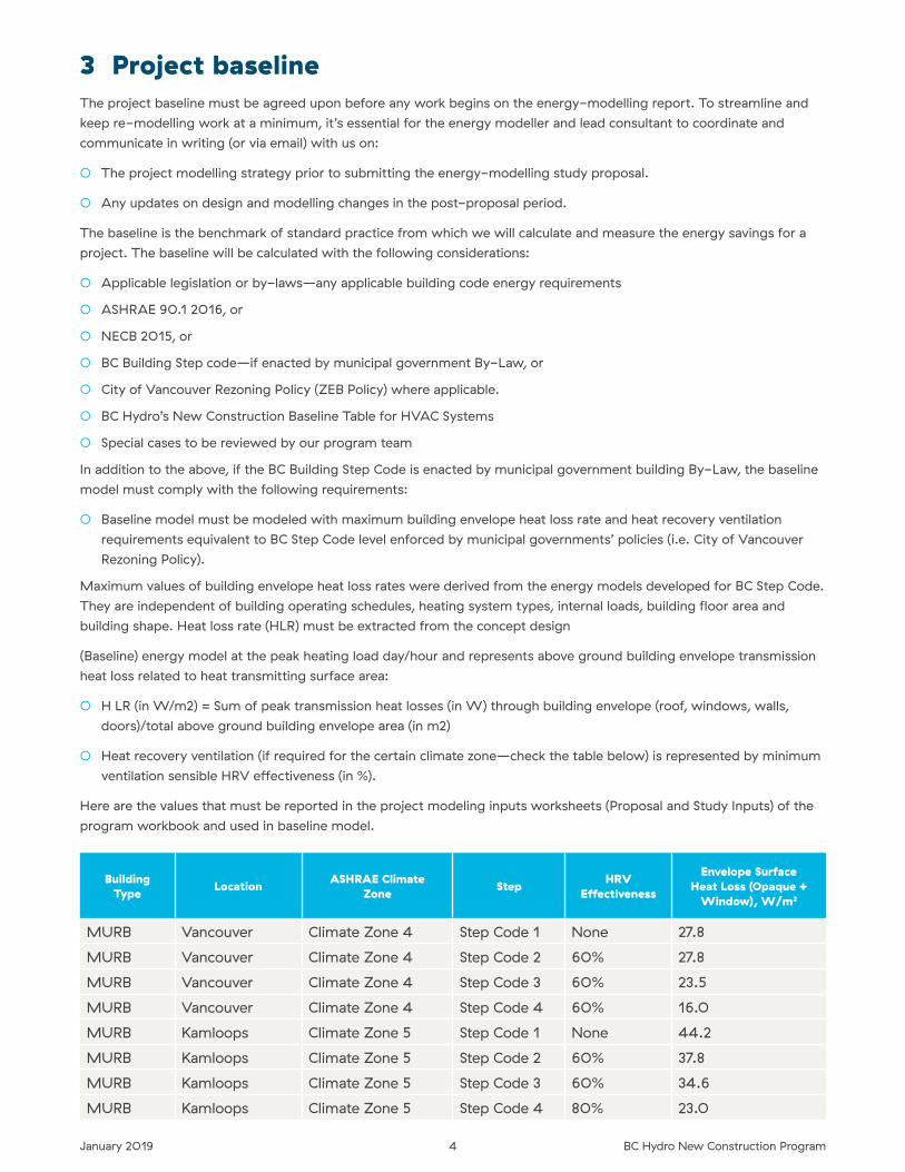
3 Project baselineThe project baseline must be agreed upon before any work begins on the energy-modelling report� To streamline and
keep re-modelling work at a minimum, it’s essential for the energy modeller and lead consultant to coordinate and
communicate in writing (or via email) with us on:
○ The project modelling strategy prior to submitting the energy-modelling study proposal�
○ Any updates on design and modelling changes in the post-proposal period�
The baseline is the benchmark of standard practice from which we will calculate and measure the energy savings for a
project� The baseline will be calculated with the following considerations:
○ Applicable legislation or by-laws—any applicable building code energy requirements
○ ASHRAE 90�1 2016, or
○ NECB 2015, or
○ BC Building Step code—if enacted by municipal government By-Law, or
○ City of Vancouver Rezoning Policy (ZEB Policy) where applicable�
○ BC Hydro’s New Construction Baseline Table for HVAC Systems
○ Special cases to be reviewed by our program team
In addition to the above, if the BC Building Step Code is enacted by municipal government building By-Law, the baseline
model must comply with the following requirements:
○ Baseline model must be modeled with maximum building envelope heat loss rate and heat recovery ventilation
requirements equivalent to BC Step Code level enforced by municipal governments’ policies (i�e� City of Vancouver
Rezoning Policy)�
Maximum values of building envelope heat loss rates were derived from the energy models developed for BC Step Code�
They are independent of building operating schedules, heating system types, internal loads, building floor area and
building shape� Heat loss rate (HLR) must be extracted from the concept design
(Baseline) energy model at the peak heating load day/hour and represents above ground building envelope transmission
heat loss related to heat transmitting surface area:
○ H LR (in W/m2) = Sum of peak transmission heat losses (in W) through building envelope (roof, windows, walls,
doors)/total above ground building envelope area (in m2)
○ Heat recovery ventilation (if required for the certain climate zone—check the table below) is represented by minimum
ventilation sensible HRV effectiveness (in %)�
Here are the values that must be reported in the project modeling inputs worksheets (Proposal and Study Inputs) of the
program workbook and used in baseline model�
Building Type Location ASHRAE Climate
Zone Step HRV Effectiveness
Envelope Surface Heat Loss (Opaque +
Window), W/m2
MURB Vancouver Climate Zone 4 Step Code 1 None 27�8
MURB Vancouver Climate Zone 4 Step Code 2 60% 27�8
MURB Vancouver Climate Zone 4 Step Code 3 60% 23�5
MURB Vancouver Climate Zone 4 Step Code 4 60% 16�0
MURB Kamloops Climate Zone 5 Step Code 1 None 44�2
MURB Kamloops Climate Zone 5 Step Code 2 60% 37�8
MURB Kamloops Climate Zone 5 Step Code 3 60% 34�6
MURB Kamloops Climate Zone 5 Step Code 4 80% 23�0
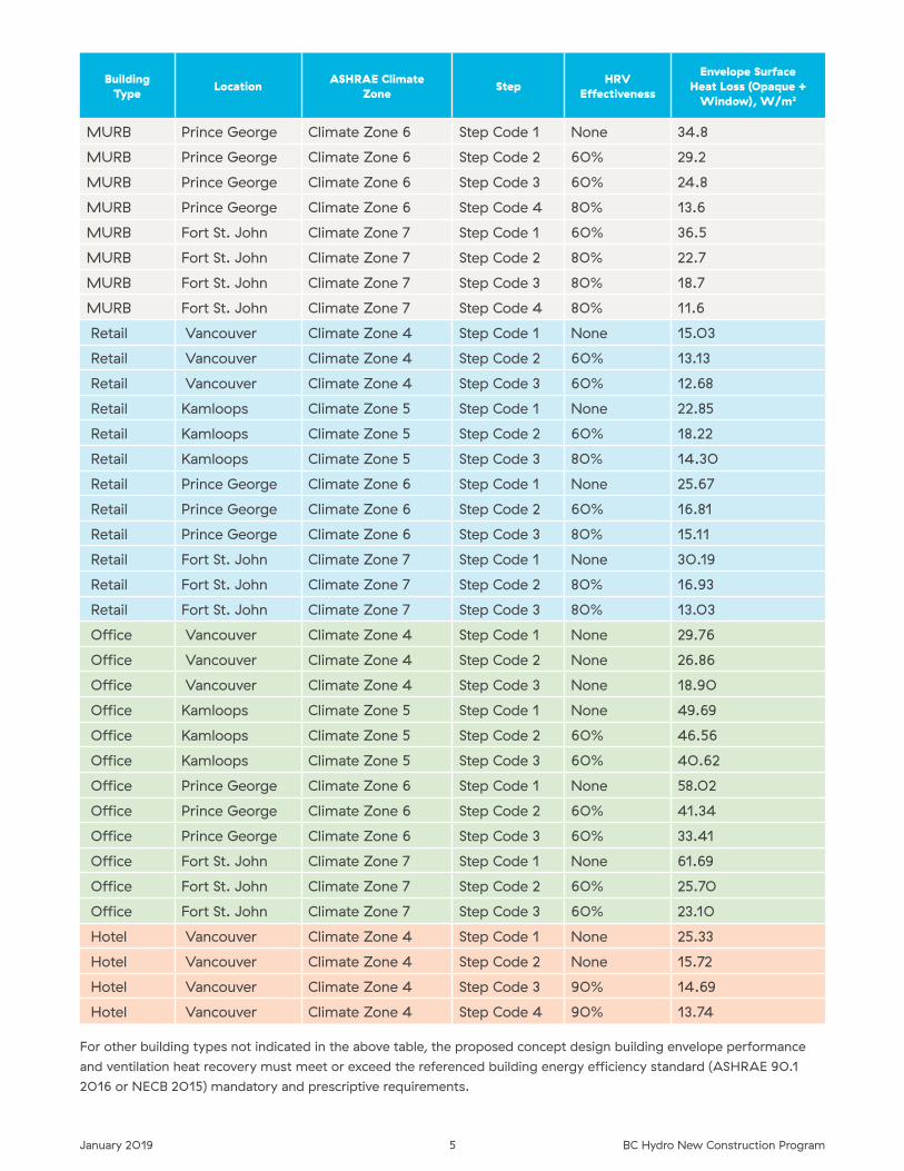
5January 2019 BC Hydro New Construction Program
Building Type Location ASHRAE Climate
Zone Step HRV Effectiveness
Envelope Surface Heat Loss (Opaque +
Window), W/m2
MURB Prince George Climate Zone 6 Step Code 1 None 34�8
MURB Prince George Climate Zone 6 Step Code 2 60% 29�2
MURB Prince George Climate Zone 6 Step Code 3 60% 24�8
MURB Prince George Climate Zone 6 Step Code 4 80% 13�6
MURB Fort St� John Climate Zone 7 Step Code 1 60% 36�5
MURB Fort St� John Climate Zone 7 Step Code 2 80% 22�7
MURB Fort St� John Climate Zone 7 Step Code 3 80% 18�7
MURB Fort St� John Climate Zone 7 Step Code 4 80% 11�6
Retail Vancouver Climate Zone 4 Step Code 1 None 15�03
Retail Vancouver Climate Zone 4 Step Code 2 60% 13�13
Retail Vancouver Climate Zone 4 Step Code 3 60% 12�68
Retail Kamloops Climate Zone 5 Step Code 1 None 22�85
Retail Kamloops Climate Zone 5 Step Code 2 60% 18�22
Retail Kamloops Climate Zone 5 Step Code 3 80% 14�30
Retail Prince George Climate Zone 6 Step Code 1 None 25�67
Retail Prince George Climate Zone 6 Step Code 2 60% 16�81
Retail Prince George Climate Zone 6 Step Code 3 80% 15�11
Retail Fort St� John Climate Zone 7 Step Code 1 None 30�19
Retail Fort St� John Climate Zone 7 Step Code 2 80% 16�93
Retail Fort St� John Climate Zone 7 Step Code 3 80% 13�03
Office Vancouver Climate Zone 4 Step Code 1 None 29�76
Office Vancouver Climate Zone 4 Step Code 2 None 26�86
Office Vancouver Climate Zone 4 Step Code 3 None 18�90
Office Kamloops Climate Zone 5 Step Code 1 None 49�69
Office Kamloops Climate Zone 5 Step Code 2 60% 46�56
Office Kamloops Climate Zone 5 Step Code 3 60% 40�62
Office Prince George Climate Zone 6 Step Code 1 None 58�02
Office Prince George Climate Zone 6 Step Code 2 60% 41�34
Office Prince George Climate Zone 6 Step Code 3 60% 33�41
Office Fort St� John Climate Zone 7 Step Code 1 None 61�69
Office Fort St� John Climate Zone 7 Step Code 2 60% 25�70
Office Fort St� John Climate Zone 7 Step Code 3 60% 23�10
Hotel Vancouver Climate Zone 4 Step Code 1 None 25�33
Hotel Vancouver Climate Zone 4 Step Code 2 None 15�72
Hotel Vancouver Climate Zone 4 Step Code 3 90% 14�69
Hotel Vancouver Climate Zone 4 Step Code 4 90% 13�74
For other building types not indicated in the above table, the proposed concept design building envelope performance
and ventilation heat recovery must meet or exceed the referenced building energy efficiency standard (ASHRAE 90�1
2016 or NECB 2015) mandatory and prescriptive requirements�
6January 2019 BC Hydro New Construction Program
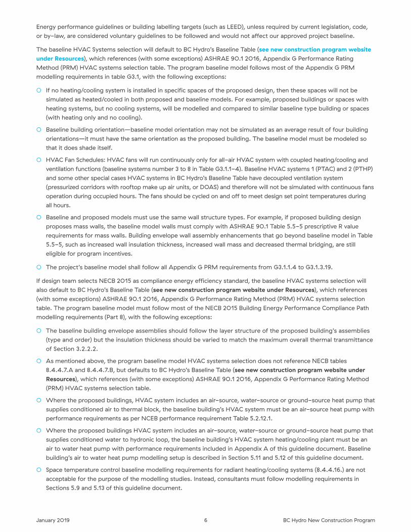
Energy performance guidelines or building labelling targets (such as LEED), unless required by current legislation, code,
or by-law, are considered voluntary guidelines to be followed and would not affect our approved project baseline�
The baseline HVAC Systems selection will default to BC Hydro’s Baseline Table (see new construction program website under Resources), which references (with some exceptions) ASHRAE 90�1 2016, Appendix G Performance Rating
Method (PRM) HVAC systems selection table� The program baseline model follows most of the Appendix G PRM
modelling requirements in table G3�1, with the following exceptions:
○ If no heating/cooling system is installed in specific spaces of the proposed design, then these spaces will not be
simulated as heated/cooled in both proposed and baseline models� For example, proposed buildings or spaces with
heating systems, but no cooling systems, will be modelled and compared to similar baseline type building or spaces
(with heating only and no cooling)�
○ Baseline building orientation—baseline model orientation may not be simulated as an average result of four building
orientations—it must have the same orientation as the proposed building� The baseline model must be modeled so
that it does shade itself�
○ HVAC Fan Schedules: HVAC fans will run continuously only for all-air HVAC system with coupled heating/cooling and
ventilation functions (baseline systems number 3 to 8 in Table G3�1�1-4)� Baseline HVAC systems 1 (PTAC) and 2 (PTHP)
and some other special cases HVAC systems in BC Hydro’s Baseline Table have decoupled ventilation system
(pressurized corridors with rooftop make up air units, or DOAS) and therefore will not be simulated with continuous fans
operation during occupied hours� The fans should be cycled on and off to meet design set point temperatures during
all hours�
○ Baseline and proposed models must use the same wall structure types� For example, if proposed building design
proposes mass walls, the baseline model walls must comply with ASHRAE 90�1 Table 5�5-5 prescriptive R value
requirements for mass walls� Building envelope wall assembly enhancements that go beyond baseline model in Table
5�5-5, such as increased wall insulation thickness, increased wall mass and decreased thermal bridging, are still
eligible for program incentives�
○ The project’s baseline model shall follow all Appendix G PRM requirements from G3�1�1�4 to G3�1�3�19�
If design team selects NECB 2015 as compliance energy efficiency standard, the baseline HVAC systems selection will
also default to BC Hydro’s Baseline Table (see new construction program website under Resources), which references
(with some exceptions) ASHRAE 90�1 2016, Appendix G Performance Rating Method (PRM) HVAC systems selection
table� The program baseline model must follow most of the NECB 2015 Building Energy Performance Compliance Path
modelling requirements (Part 8), with the following exceptions:
○ The baseline building envelope assemblies should follow the layer structure of the proposed building’s assemblies
(type and order) but the insulation thickness should be varied to match the maximum overall thermal transmittance
of Section 3�2�2�2�
○ As mentioned above, the program baseline model HVAC systems selection does not reference NECB tables
8�4�4�7�A and 8�4�4�7�B, but defaults to BC Hydro’s Baseline Table (see new construction program website under Resources), which references (with some exceptions) ASHRAE 90�1 2016, Appendix G Performance Rating Method
(PRM) HVAC systems selection table�
○ Where the proposed buildings, HVAC system includes an air-source, water-source or ground-source heat pump that
supplies conditioned air to thermal block, the baseline building’s HVAC system must be an air-source heat pump with
performance requirements as per NCEB performance requirement Table 5�2�12�1�
○ Where the proposed buildings HVAC system includes an air-source, water-source or ground-source heat pump that
supplies conditioned water to hydronic loop, the baseline building’s HVAC system heating/cooling plant must be an
air to water heat pump with performance requirements included in Appendix A of this guideline document� Baseline
building’s air to water heat pump modelling setup is described in Section 5�11 and 5�12 of this guideline document�
○ Space temperature control baseline modelling requirements for radiant heating/cooling systems (8�4�4�16�) are not
acceptable for the purpose of the modelling studies� Instead, consultants must follow modelling requirements in
Sections 5�9 and 5�13 of this guideline document�
7January 2019 BC Hydro New Construction Program
3.1 Modelling resources
COMNET COMMERCIAL BUILDINGS ENERGY MODELLING GUIDELINES AND PROCEDURES
This energy-modelling resource is available for download at: http://www.comnet.org/mgp-manual�
The manual offers guidance to building energy modelers, ensuring technically rigorous and credible assessment of
energy performance for commercial and multi-unit residential buildings� It provides a streamlined process that can be
used with various existing modelling software and systems, across a range of programs�
DOE COMMERCIAL PROTOT YPE BUILDING MODELS
This energy modelling resource is available for download
at: http://www.energycodes.gov/commercial-prototype-building-models
These prototype buildings—derived from DOE’s Commercial Reference Building Models—cover all Reference Building
types (with the exception of supermarkets), and also an additional prototype representing high-rise apartment buildings�
As Standard 90�1 evolves, PNNL makes modifications to the commercial prototype building models, with extensive input
from ASHRAE 90�1 Standing Standards Project Committee members and other building industry experts�
BUILDING AMERICA BENCHMARK RESEARCH
The Building America Analysis Spreadsheets are available in a New Construction version at:
http://energy.gov/eere/buildings/building-america-analysis-spreadsheets
The spreadsheets provide the set of standard operating conditions—including hourly and monthly profiles for occupancy,
lighting, appliances, and miscellaneous electric loads (MELs)—developed by Building America to objectively compare
energy use before and after a retrofit, and against a Benchmark new construction building�
ENERGY STAR MULTI FAMILY HIGH RISE PROGRAM SIMUL ATION GUIDELINES
This energy modelling resource is available for download at:
http://www.energystar.gov/ia/partners/bldrs_lenders_raters/downloads/mfhr/ENERGY_STAR_MFHR_Simulation_Guidelines_Version_1.0_Rev02.pdf?4a08-e48f
8January 2019 BC Hydro New Construction Program
4 Energy modelling study submission requirementsThe program requires the submission of the Energy Modelling Study Proposal and Report Workbook� This workbook
was developed by the program to serve three purposes:
1. To standardize energy study reporting format�
2. To show required information and inputs needed from consultants for the technical review in the proposal and study
approval process�
3. To minimize duplication in documenting and submitting information for review phases (proposal and study reviews)�
This workbook is to be completed and returned in digital format, as part of the mandatory requirements for energy study
funding under the program� It includes the Life Cycle Cost (LCC) analysis spreadsheet and Incremental Capital Cost
Calculation (ICCC) spreadsheet� It is highly recommended that consultants read the instruction worksheet which has
detailed step by step instructions before they use the workbook for the first time�
4.1 Energy study proposalAt the energy study proposal stage, the workbook (with completed proposal worksheet) is to be submitted along with
the project application and consultants’ proposal(s)� Consultants are welcome to submit the proposals to the customer in
their preferable proposal format� However, the consultant’s proposal(s) do not need to contain project technical details,
but just a reference to this workbook (proposal worksheet tab only)� Our program engineer will use this worksheet to
review the proposed modelling study scope and cost� The modelling consultant will fill out all applicable fields to the best
of their knowledge� Multi-type building projects should have inputs broken down by major building type (i�e� more than
10% of combined conditioned area)�
4.2 Energy study reportAt the energy study report stage, this workbook is the only document that we require for study review� Consultants are
welcome to organize and present the study results to the customer in their preferred format� This customer oriented
report could be in an executive summary format and have the study report workbook referenced as an appendix� This
executive summary should include the study report intent a brief building description, and a brief description of the
baseline building model and the ECMs to be studied� A summary table can be provided with the energy savings and
capital costing numbers�
The approved study proposal workbook must be used as starting point for study report inputs� The study inputs
worksheet tab (automatically populated at the proposal stage) must be updated at the study report submission stage�
During the detailed design and modelling stage, modelling inputs agreed upon at the proposal stage may change and
this worksheet should capture all those changes� Edited cells will be automatically highlighted in yellow to give an
indication to both the modeller and reviewer that assumptions/inputs have been changed from the proposal stage�
The study results worksheet is the central location for all simulation results (baseline, EPM, ECMs and proposed bundle)�
If this worksheet is properly filled out, LCC analysis and our summary worksheets will be automatically populated� At the
same time, the ICCC worksheet will automatically add ECM names of modelled measures� The energy modeller must
add ECM details required for the cost consultant to fill out the costing information� Alternatively, the cost consultant can
submit the costing information in their own preferred format, and the modelling consultant must then copy over those
numbers to the ICCC worksheet in the study report workbook�
The hourly simulation results (8,760 hours) from the simulation program for both baseline and proposed models must be
copied into Baseline and Proposed Models’ Hourly Results worksheet tabs� Results in these worksheets are to show total
building electricity and gas and for each major building type separately�
Any additional building systems and modelling process details/descriptions must be added at the bottom of the
worksheet� If required, consultants are also welcome to add additional worksheets to the end of this workbook with
additional calculations and project details�
Please refer to the instructions worksheet tab for more specific worksheet inputs details�
9January 2019 BC Hydro New Construction Program
4.3 Post-tender energy study report update (if applicable)Post-tender modelling updates will be required in the event that the building design and/or building size has been
significantly changed after the approval of the pre-tender study report, and in cases where some of approved ECMs
have been excluded by the applicant after the tender�
In this case, the study report workbook must be updated (study inputs, study results and ICCC worksheets) and
resubmitted to the program engineer for additional review� The additional modelling and reporting fees can be
submitted to the program engineer for approval with a proper justification and estimate of additional modelling hours
required to complete this task� Note that additional funding support plus the the initial funding support must not exceed
the specified maximum amounts set in the Program Orientation Manual�
4.4 Lighting calculatorLighting ECMs must be coordinated with electrical consultant and modelled along with other measures using the space
by space approach� The Lighting Calculator (in Excel format, downloadable from bchydro.com/nclighting) must be
completed by an electrical consultant based on the final lighting design (or as-built) and submitted along with associated
lighting drawings and luminaire specification sheets (in PDF format) to the project KAM prior to project site inspection�
5 Other modelling requirements5.1 Windows to wall ratio (WWR)ASHRAE 90�1 2016� The baseline building model vertical fenestration percentage of gross above-grade wall area shall
follow Appendix G PRM requirement 5�c in Table G3�1: For building area types included in Table G3�1�1-1 vertical
fenestration areas shall equal that in Table G3�1�1-1 based on the area of gross above-grade walls that separate
conditioned spaces and semi-heated spaces from the exterior� For building areas not shown in Table G3�1�1-1 vertical
fenestration areas in baseline model shall equal that in the proposed design model or 40% of gross above-grade wall
area, whichever is smaller� Baseline skylight area shall be equal to that in the proposed design model or 3%, whichever
is smaller�
NECB 2015� The Fenestration and Door area to gross Wall area Ratio(FDWR) requirements for whole building design
baseline FDWR align with NECB requirement 3�2�1�4� but it must be the same with the proposed FDWR below
maximum allowable percentage for specific climate zone (represented by HDD)�
However, modelling requirements for the projects with proposed WWR (and FDWR) higher than 40% are as follows:
1. Run the baseline model with 40% WWR� Provide energy consumption by end-use breakdown in the report�
2. Run an Energy Penalty Measure (EPM) which is actually the same baseline model in step 1, but with higher WWR
(as proposed by design, but assume 80% as an example)� Include the energy consumption by end-use breakdown
table for this measure in the report, along with negative energy consumption and demand saving numbers
(incremental capital cost estimate is required for EPM as well)� The main purpose of EPM is to provide information to
client about energy penalty that will need to be overcome by implementing different types of ECMs�
3. Run all proposed ECM simulations with proposed WWR (as proposed by design, but assume 80% as an example)�
All ECM energy savings numbers will represent a difference between EPM’s (80% WWR) consumption and ECM’s
energy consumption� Include the energy consumption by end-use breakdown tables for all analyzed measures in the
report and energy consumption and demand saving numbers, along with incremental capital cost estimates� (Note
that incremental capital cost for each ECM will represent a difference between EPM and ECM capital cost�)
4. Run recommended bundle of ECMs with proposed WWR (80% in this case)� Note that the bundle energy saving
number will represent a difference between the baseline (40% WWR) model’s consumption and recommended
bundle’s energy consumption (and therefore will include negative energy penalty of higher glazing percentage)�
Include the energy consumption by end-use breakdown table for the bundle in the report and energy consumption
and demand saving numbers, along with incremental capital cost estimate� A bundle incremental capital cost will
represent a cost difference between baseline and bundle capital cost� The program capital incentive will be
calculated based on the recommended bundle saving results�
10January 2019 BC Hydro New Construction Program
5.2 Building envelope thermal bridging and effective building envelope opaque u-valuesEffective May 1st, 2015, the program requires effective building envelope opaque U-values calculation/reporting/usage
referencing the methodology and data presented in Building Envelope Thermal Bridging Guide (BETBG)� The low
resolution version of the guide can be downloaded from the program web page under “resources�” Each energy study
report submission (regardless of inclusion of building envelope ECMs) must report opaque building envelope effective
U-values calculations and include them in both baseline and proposed models�
It is known in industry that the current prescriptive opaque envelope U-values in many energy codes, including ASHRAE
90�1 2016 and NECB 2015, represents only clear wall structure assembly U-values, but they do not include the additional
heat loss from the building envelope interface details� The BETBG research has shown that thermal bridging at interface
details, especially at slabs, parapets and glazing transitions can be sources of significant heat flow through the building
envelope� These additional heat flows were not accounted for in envelope heat loss calculations, which resulted in
overestimated building envelope performance in building simulations�
To help consultants perform the effective opaque U-values calculations, the program has provided the Enhanced
Thermal Performance Spreadsheet which is also available on the program’s web page under “resources�” This enhanced
spreadsheet is intended to be a helpful tool in combining thermal performance values for building assemblies into an
overall R- and U-value� The methodology for calculations in this spreadsheet follows the approach given in the BETBG�
Submission of this spreadsheet (or consultant’s spreadsheet with similar format), along with the Energy Modelling Study
Proposal/Report Workbook, is mandatory for a project submission in the program�
BASELINE BUILDING MODELS
It would be unfair to compare effective building envelope opaque U-values (that takes in account major building
envelope interface details thermal bridging) with the baseline clear envelope assembly U-values prescribed by ASHRAE
or NECB energy codes� Additionaly, we understand that the baseline building is a fictitious code-compliant building
without building envelope architectural details required for a proper building envelope interface details selection� Based
on the research conducted for the BETBG, we requested Morrison Hershfield to develop a methodology for “de-rating”
the base building envelope or prescriptive U-values found in energy codes, based on inclusion of thermal bridging at
interface details� Two alternative methods for determining baseline building U-values (that account for interface details)
are presented in the report “Accounting for Thermal Bridging at Interface Details—A Methodology for De-Rating
Prescriptive Opaque Envelope Requirements in Energy Codes”, which can be downloaded from the program webpage,
under “resources�” The program has adopted Method 1—Simplified Approach� This approach is simple and does not
require the use of base building effective U-values calculations� To help consultants select the appropriate effective
baseline opaque U-values, the program has provided Base Building U-value calculator in the second tab of the
“Enhanced Thermal Performance Spreadsheet”�
PROPOSED BUILDING MODELS
Effective opaque U-values calculations will be required for the proposed building envelope design� These calculations
can be performed by energy modellers, architects or building envelope consultants� If performed by the energy modeller,
selection of details will require discussion/coordination with the architect and/or building envelope consultant� A good
collaboration within design team is essential for the success of the project�
Effective opaque U-values step-by-step calculation methodology is provided in the BETBG in section 1�4—“Example
Utilization of the Catalogue”� In addition to this, recommended calculation/modelling methodology during the concept
and detailed modelling stage (along with calculations Excel file example and set of example PDF drawings) is provided in
the “Building Envelope Thermal Bridging Guide Working Example” package on the program web page�
Building energy simulation software commonly used in Canada currently does not have capabilities to directly input linear
transmittance values into energy simulations� Some modelling programs already de-rate insulation layers to account for
steel studs, but this takes in account only thermal bridging through clear wall assemblies, and does not take in account
most influential building envelope interface details (slabs, parapets, window to wall transitions)� The overall U-value that
includes the effects of linear and points transmittances must first be determined without the assistance of the energy
modelling software to ensure that the correct thermal transmittances will be processed by the model�
11January 2019 BC Hydro New Construction Program
Many modelling programs use construction layers to build up the building envelope assemblies based on material
properties� To account for thermal bridging, all the material properties should be left as is, while only the insulating layer
R-value should be de-rated such that the correct overall U-value determined from calculation is matched with the
output by the software� This method allows for the functions that account for thermal mass to be approximated by
the software�
The clear field U-values can be determined using tables in the appendix A of the ASHRAE 90�1 2016 standard� This
appendix has tables for example steel stud wall assemblies, but there are a numbers of other tables for other types of
assemblies� If the clear field envelope assemblies are substantially different from what is in the appendix A tables, they
can always be calculated using BETBG� BETBG has an extensive catalogue of 300+ assemblies including clear field
U-values for a variety of constructions and configurations�
The clear field U-values given in the BETBG catalogue are based on the ASHRAE 1365-RP methodology, which include
air films� Many energy modelling programs calculate air films separately� The air films for the modeled details in this
BETBG are listed with the material properties in each of the details in appendix A� The thermal resistance of these air
films may need to be subtracted out before entering R- or U-values into an energy modelling program�
5.3 Mechanical ventilationBCBC indicates that mechanical ventilation systems, not specifically described in ventilation subsection, must be
designed, constructed and installed as described in ASHRAE Handbooks and Standards�
BCBC and Vancouver Building By-Law (VBBL) references ASHRAE 62�1 2001(excluding addendum N) version for
ventilation rates�
NECB 2015 specifies that minimum rates as per code should be used, which means ASHRAE 62�1 2001 (excluding
addendum N) version�
ASHRAE Standard 90�1-2010 lists ASHRAE Standard 62�1-20013 in its table of references�
The program references also ASHRAE 62�1 2013 whenever BCBC does not specifically prescribe ventilation rates, or does
not reference specific ventilation standard�
Mechanical ventilation rates should be consistent in baseline and proposed model� The only exception to this rule is a
proposed design with displacement ventilation system decoupled from heating/cooling system (supply air temperature is
cooler than room air and delivered at a low velocity to achieve unidirectional flow and thermal stratification)� In that case,
a ventilation effectiveness credit can be applied to the proposed model in terms of using higher zone air distribution
effectiveness Ez of 1�2 (as described in ASHRAE 62�1 Standard) in calculation of the minimum zone outdoor air rate�
Mechanical ventilation of underground garages must comply with BCBC 6�2�2�3� requirements� If not specified
otherwise, intermittent garage exhaust fans operation must be modeled with a four hr/day runtime for MURB garages
and with a six hr/day runtime for commercial garages� Both baseline and proposed models must be modelled with the
same garage ventilation control strategies prescribed by BCBC�
RESIDENTIAL VENTIL ATION
For BCBC Part 3 MURBs, the program references BCBC which prescribes minimum dwelling units ventilation
requirements in 6�2�2�1 as well as in 9�32�3�3, 9�32�3�4 and 9�32�3�5� The MURB baseline building design dwelling units
ventilation rates must be modeled the same as the proposed design ventilation rates up to 50% higher than BCBC
requirements� If the ventilation in the proposed design exceeds BCBC by more than 50%, the baseline must be modeled
as 50% above BCBC�
BCBC (and therefore new construction program) references ASHRAE 62�1-2001 standard ventilation rates for all spaces
in Part 3 residential buildings� However, for self-contained mechanical ventilation systems serving only one dwelling unit,
required ventilation must comply with Part 6�2�2 or Subsection 9�32�3�
Dwelling units’ kitchen and bathroom fans (with intermittent operation) must be modelled in both baseline and proposed
models using the same exhaust ventilation rates, which do not exceed the rates provided in BCBC Table 9�32�3�3�B by
more than 50%� If not specified otherwise, intermittent exhaust must be modelled with a two hr/day runtime�
12January 2019 BC Hydro New Construction Program
On September 17, 2014, the Building and Safety Standards Branch issued the Bulletin No� B14-05 which outlines
changes related to residential dwelling units ventilation� Here is a brief overview of the proposed changes:
Effective December 19, 2014 residential dwelling units, such as houses, apartments and secondary suites will be required
to have a principal ventilation system that exhausts air from bathrooms and kitchens and supplies fresh air to bedrooms
and living areas [9�32�3�3�]� The principal ventilation system is intended to create a continuous flow of air through the
dwelling unit, making it easier to control issues related to moist and contaminated air, such as mold and mildew� To
satisfy the exhaust requirements of a principal ventilation system, every dwelling unit needs to have one fan that exhausts
air continuously (24hr/day) at the minimum exhaust rates outlined in Table 9�32�3�5� Some small dwelling units in mild
climates are permitted to supply fresh air through passive vents [9�32�3�4�(6)], but for most dwelling units exhaust and
supply will require a mechanical fan� [Copied from Bulletin No� B14-05]�
As per these new ventilation requirements, a principal ventilation system must mechanically provide supply air to living
room and each bedroom (except as provided in 9�32�3�4 (6)� These BCBC ventilation requirements are optional for
self-contained ventilation systems in Part 3 MURBs dwelling units (as indicated in 6�2�2�1�(3))� In such cases previous
standard market practice MURB ventilation system (over-pressurized corridors with door undercuts for ventilation air
supply) will not be accepted as program baseline residential ventilation system�
The BCBC provides five separate compliance paths for mechanical distribution of supply air that utilize different systems,
including forced-air heating systems, HRV’s, ERV’s, and central-recirculation ventilation systems [9�32�3�4�]� To eliminate
any modelling re-work, it is essential for an energy modeller to communicate and coordinate proposed and baseline
ventilation modelling strategy with the program engineer�
5.4 Natural ventilation (with passive cooling)In case of “passive cooling by natural ventilation,” the program follows LEED Canada 2009 modelling guideline:
1. Demonstrate that common practice for similar buildings within the same climate zone and market segment of the
LEED project is to install vapour-compression cooling systems� For this purpose, the comparable buildings must
have similar occupancy type(s), densities and schedules, and similar conditioned floor areas� (In this case, a survey of
similar projects of similar building type in the region would be acceptable�)
2. A detailed hourly analysis of the peak cooling periods must demonstrate that the proposed building design applying
passive cooling energy efficiency approaches can maintain comfortable conditions acceptable to the building
occupants (a narrative and psychrometric analysis or a building energy modelling report that demonstrates that
acceptable comfort conditions are provided for 98% of the year as per the LEED NC 1�0 Reference Manual)�
3. The passive cooling energy efficiency approaches must be permanent (e�g�, window overhang) or automatically
controlled (e�g�, opening of dampers by a BAS)� Manual measures that rely on occupant control can only be included
in the model if comprehensive training and Operations & Maintenance manuals are provided to occupants�
4. The same energy analysis tool(s) must be used for both the proposed and baseline building models to predict energy
performance� The analysis tool(s) used must be suited for the proposed passive cooling energy
efficiency approaches�
5. The space temperature cooling and heating set points in the baseline building model must result in similar indoor
temperatures to those exhibited in the proposed building model� Additionally, the proposed building model must
capture all potential energy impacts associated with the operation of the natural ventilation systems in the heating
mode including the infiltration of undesirable levels of cold air�
Appropriate thermal comfort analysis (Percentage People Dissatisfied—PPD) must be provided�
5.5 Service water heatingBaseline and proposed average daily service hot water demands must be used from the ASHRAE 90�1 2016 User’s
Manual Table 7-B (Source: Table 7, Chapter 49 of the 2007 ASHRAE Handbook—HVAC Applications)� These demands
are aligned well with the results of the latest ASHRAE research projects�
13January 2019 BC Hydro New Construction Program
5.6 Plug loads
NON-RESIDENTIAL BUILDINGS
Baseline and proposed plug loads (Receptacle Power Densities) for all buildings (except MURBs) must be used from the
ASHRAE 90�1 2016 User’s Manual Table G-D� These power densities are aligned well with the results of the latest
ASHRAE research projects�
If design team selects NECB 2015 as compliance energy efficiency standard, the baseline and proposed plug loads must
be used from the NECB 2015 Appendix A Table A-8�4�3�2�(2)-A� and Table A-8�4�3�2�(2)-B
RESIDENTIAL BUILDINGS
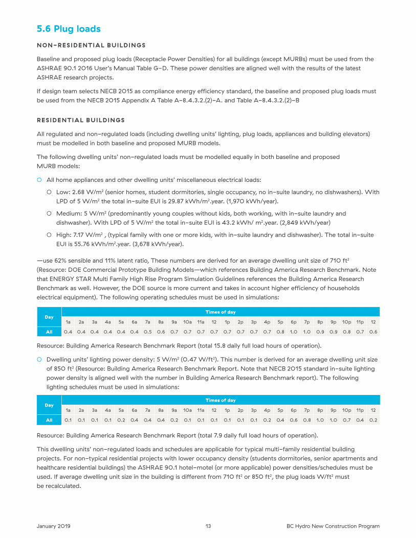
All regulated and non-regulated loads (including dwelling units’ lighting, plug loads, appliances and building elevators)
must be modelled in both baseline and proposed MURB models�
The following dwelling units’ non-regulated loads must be modelled equally in both baseline and proposed
MURB models:
○ All home appliances and other dwelling units’ miscellaneous electrical loads:
○ Low: 2�68 W/m2 (senior homes, student dormitories, single occupancy, no in-suite laundry, no dishwashers)� With
LPD of 5 W/m2 the total in-suite EUI is 29�87 kWh/m2�year� (1,970 kWh/year)�
○ Medium: 5 W/m2 (predominantly young couples without kids, both working, with in-suite laundry and
dishwasher)� With LPD of 5 W/m2 the total in-suite EUI is 43�2 kWh/ m2�year� (2,849 kWh/year)
○ High: 7�17 W/m2 , (typical family with one or more kids, with in-suite laundry and dishwasher)� The total in-suite
EUI is 55�76 kWh/m2�year� (3,678 kWh/year)�
—use 62% sensible and 11% latent ratio, These numbers are derived for an average dwelling unit size of 710 ft2
(Resource: DOE Commercial Prototype Building Models—which references Building America Research Benchmark� Note
that ENERGY STAR Multi Family High Rise Program Simulation Guidelines references the Building America Research
Benchmark as well� However, the DOE source is more current and takes in account higher efficiency of households
electrical equipment)� The following operating schedules must be used in simulations:
DayTimes of day
1a 2a 3a 4a 5a 6a 7a 8a 9a 10a 11a 12 1p 2p 3p 4p 5p 6p 7p 8p 9p 10p 11p 12
All 0�4 0�4 0�4 0�4 0�4 0�4 0�5 0�6 0�7 0�7 0�7 0�7 0�7 0�7 0�7 0�7 0�8 1�0 1�0 0�9 0�9 0�8 0�7 0�6
Resource: Building America Research Benchmark Report (total 15�8 daily full load hours of operation)�
○ Dwelling units’ lighting power density: 5 W/m2 (0�47 W/ft2)� This number is derived for an average dwelling unit size
of 850 ft2 (Resource: Building America Research Benchmark Report� Note that NECB 2015 standard in-suite lighting
power density is aligned well with the number in Building America Research Benchmark report)� The following
lighting schedules must be used in simulations:
DayTimes of day
1a 2a 3a 4a 5a 6a 7a 8a 9a 10a 11a 12 1p 2p 3p 4p 5p 6p 7p 8p 9p 10p 11p 12
All 0�1 0�1 0�1 0�1 0�2 0�4 0�4 0�4 0�2 0�1 0�1 0�1 0�1 0�1 0�1 0�2 0�4 0�6 0�8 1�0 1�0 0�7 0�4 0�2
Resource: Building America Research Benchmark Report (total 7�9 daily full load hours of operation)�
This dwelling units’ non-regulated loads and schedules are applicable for typical multi-family residential building
projects� For non-typical residential projects with lower occupancy density (students dormitories, senior apartments and
healthcare residential buildings) the ASHRAE 90�1 hotel-motel (or more applicable) power densities/schedules must be
used� If average dwelling unit size in the building is different from 710 ft2 or 850 ft2, the plug loads W/ft2 must
be recalculated�
14January 2019 BC Hydro New Construction Program
5.7 Lighting power densities and schedulesBaseline lighting power densities in non-dwelling unit spaces must be modelled as per ASHRAE 90�1 2016 Table 9�6�1�
Baseline and proposed lighting schedules (if not specified differently) must be modelled as per Tables G-D to G-M in
ASHRAE 90�1 2016 User’s Manual�
If design team selects NECB 2015 as compliance energy efficiency standard, the baseline lighting power densities in
non-dwelling units spaces must be modelled as per NECB 2015 Table 4�2�1�6� Baseline and proposed lighting schedules
(if not specified differently) must be modelled as per Tables A-8�4�3�2(1)A to K�
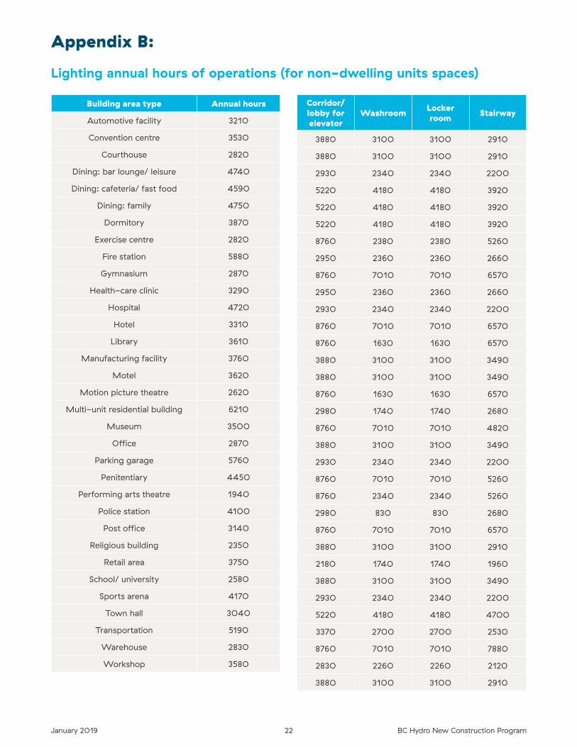
Total annual lighting hours of operations used in the Lighting Calculator are provided in appendix B as a reference� The
modelled lighting hours of operation must be reasonably close to these numbers to avoid significant discrepancy in
lighting energy savings�
5.7.1 Modeling of lighting controls
A. BASELINE BUILDING INTERIOR LIGHTING
○ Occupancy based/time limiting controls mandated in Section 9�4 (Std 90�1-2016) or in Part 4�2�2 (NECB 2015) must be
modelled through adjustment of the lighting operating schedules (refer to Tables G-D to G-M in ASHRAE/IES Std�90�1-
2016 User’s Manual, NECB 2015 Tables A-8�4�3�2 (1) A to K, and Appendix B of the current document)�
○ Daylighting controls required in Sections 9�4�1�4 and 9�4�1�5 (Std 90�1-2016) or in 4�2�2�4 and 4�2�2�8 (NECB 2015)
must be modelled explicitly in the internal daylighting module of the modeling software�
B. PROPOSED BUILDING INTERIOR LIGHTING
○ Occupancy based/time limiting controls in spaces where they are not mandated by Std 90�1-2016 or NECB 2015, must
be modelled either through adjustment of the lighting operating schedules (if the routine occupancy/ space use pattern is
well known) or by the lighting power adjustment factors listed in Std 90�1-2016 Table G3�7�
○ Daylighting controls must be modelled explicitly in the internal daylighting module of the modeling software�
IMPORTANT!
If both interior LPD reduction and interior lighting control ECMs are proposed for the project, two simulations must
be run:
1. Interior LPD Reduction ECM only
2. Combined interior LPD reduction AND interior lighting controls ECM
C. BASELINE BUILDING EX TERIOR LIGHTING
○ All exterior lighting controls must be modelled in accordance to Sections 9�4�1�4 (Std 90�1-2016) or 4�2�4�1 (NECB 2015)
through adjustment of the lighting operating schedules and power where required�
D. PROPOSED BUILDING EX TERIOR LIGHTING
The additional exterior lighting controls, not mandated by Std 90�1-2016 or NECB 2015, must be modelled through
adjustment of the lighting operating schedules and power where applicable�
Non-tradable areas’ lighting controls must be modelled identically for both baseline and proposed buildings; only lighting
for tradable areas with advancement in lighting controls are eligible for funding�
IMPORTANT!
If both, Exterior LPD Reduction and Exterior Lighting Controls ECMs are proposed for the project, two simulations must
be run:
1. Exterior LPD reduction ECM only�
2. Combined exterior LPD reduction AND exterior lighting controls ECM�
15January 2019 BC Hydro New Construction Program
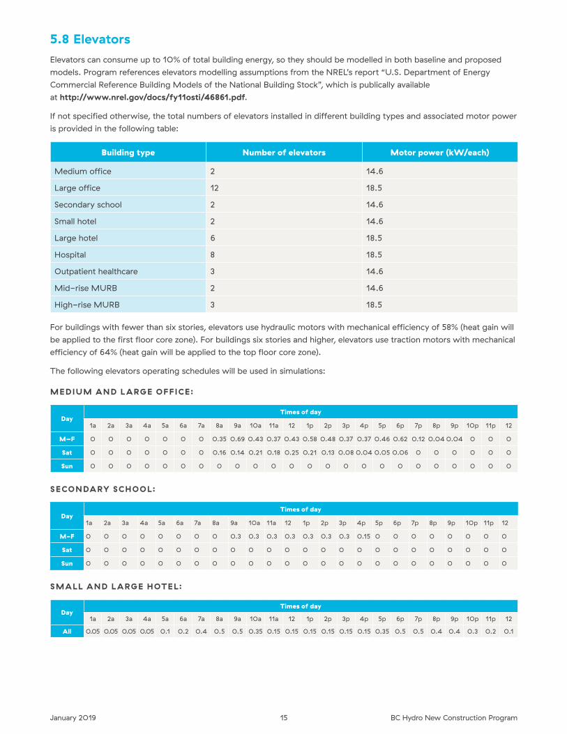
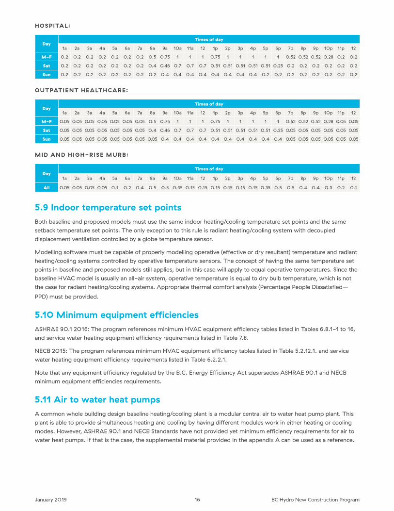
5.8 ElevatorsElevators can consume up to 10% of total building energy, so they should be modelled in both baseline and proposed
models� Program references elevators modelling assumptions from the NREL’s report “U�S� Department of Energy
Commercial Reference Building Models of the National Building Stock”, which is publically available
at http://www.nrel.gov/docs/fy11osti/46861.pdf�
If not specified otherwise, the total numbers of elevators installed in different building types and associated motor power
is provided in the following table:
Building type Number of elevators Motor power (kW/each)
Medium office 2 14�6
Large office 12 18�5
Secondary school 2 14�6
Small hotel 2 14�6
Large hotel 6 18�5
Hospital 8 18�5
Outpatient healthcare 3 14�6
Mid-rise MURB 2 14�6
High-rise MURB 3 18�5
For buildings with fewer than six stories, elevators use hydraulic motors with mechanical efficiency of 58% (heat gain will
be applied to the first floor core zone)� For buildings six stories and higher, elevators use traction motors with mechanical
efficiency of 64% (heat gain will be applied to the top floor core zone)�
The following elevators operating schedules will be used in simulations:
MEDIUM AND L ARGE OFFICE:
DayTimes of day
1a 2a 3a 4a 5a 6a 7a 8a 9a 10a 11a 12 1p 2p 3p 4p 5p 6p 7p 8p 9p 10p 11p 12
M–F 0 0 0 0 0 0 0 0�35 0�69 0�43 0�37 0�43 0�58 0�48 0�37 0�37 0�46 0�62 0�12 0�04 0�04 0 0 0
Sat 0 0 0 0 0 0 0 0�16 0�14 0�21 0�18 0�25 0�21 0�13 0�08 0�04 0�05 0�06 0 0 0 0 0 0
Sun 0 0 0 0 0 0 0 0 0 0 0 0 0 0 0 0 0 0 0 0 0 0 0 0
SECONDARY SCHOOL:
DayTimes of day
1a 2a 3a 4a 5a 6a 7a 8a 9a 10a 11a 12 1p 2p 3p 4p 5p 6p 7p 8p 9p 10p 11p 12
M-F 0 0 0 0 0 0 0 0 0�3 0�3 0�3 0�3 0�3 0�3 0�3 0�15 0 0 0 0 0 0 0 0
Sat 0 0 0 0 0 0 0 0 0 0 0 0 0 0 0 0 0 0 0 0 0 0 0 0
Sun 0 0 0 0 0 0 0 0 0 0 0 0 0 0 0 0 0 0 0 0 0 0 0 0
SMALL AND L ARGE HOTEL:
DayTimes of day
1a 2a 3a 4a 5a 6a 7a 8a 9a 10a 11a 12 1p 2p 3p 4p 5p 6p 7p 8p 9p 10p 11p 12
All 0�05 0�05 0�05 0�05 0�1 0�2 0�4 0�5 0�5 0�35 0�15 0�15 0�15 0�15 0�15 0�15 0�35 0�5 0�5 0�4 0�4 0�3 0�2 0�1
16January 2019 BC Hydro New Construction Program
HOSPITAL:
DayTimes of day
1a 2a 3a 4a 5a 6a 7a 8a 9a 10a 11a 12 1p 2p 3p 4p 5p 6p 7p 8p 9p 10p 11p 12
M-F 0�2 0�2 0�2 0�2 0�2 0�2 0�2 0�5 0�75 1 1 1 0�75 1 1 1 1 1 0�52 0�52 0�52 0�28 0�2 0�2
Sat 0�2 0�2 0�2 0�2 0�2 0�2 0�2 0�4 0�46 0�7 0�7 0�7 0�51 0�51 0�51 0�51 0�51 0�25 0�2 0�2 0�2 0�2 0�2 0�2
Sun 0�2 0�2 0�2 0�2 0�2 0�2 0�2 0�2 0�4 0�4 0�4 0�4 0�4 0�4 0�4 0�4 0�2 0�2 0�2 0�2 0�2 0�2 0�2 0�2
OUTPATIENT HEALTHCARE:
DayTimes of day
1a 2a 3a 4a 5a 6a 7a 8a 9a 10a 11a 12 1p 2p 3p 4p 5p 6p 7p 8p 9p 10p 11p 12
M-F 0�05 0�05 0�05 0�05 0�05 0�05 0�05 0�5 0�75 1 1 1 0�75 1 1 1 1 1 0�52 0�52 0�52 0�28 0�05 0�05
Sat 0�05 0�05 0�05 0�05 0�05 0�05 0�05 0�4 0�46 0�7 0�7 0�7 0�51 0�51 0�51 0�51 0�51 0�25 0�05 0�05 0�05 0�05 0�05 0�05
Sun 0�05 0�05 0�05 0�05 0�05 0�05 0�05 0�05 0�4 0�4 0�4 0�4 0�4 0�4 0�4 0�4 0�4 0�4 0�05 0�05 0�05 0�05 0�05 0�05
MID AND HIGH-RISE MURB:
DayTimes of day
1a 2a 3a 4a 5a 6a 7a 8a 9a 10a 11a 12 1p 2p 3p 4p 5p 6p 7p 8p 9p 10p 11p 12
All 0�05 0�05 0�05 0�05 0�1 0�2 0�4 0�5 0�5 0�35 0�15 0�15 0�15 0�15 0�15 0�15 0�35 0�5 0�5 0�4 0�4 0�3 0�2 0�1
5.9 Indoor temperature set pointsBoth baseline and proposed models must use the same indoor heating/cooling temperature set points and the same
setback temperature set points� The only exception to this rule is radiant heating/cooling system with decoupled
displacement ventilation controlled by a globe temperature sensor�
Modelling software must be capable of properly modelling operative (effective or dry resultant) temperature and radiant
heating/cooling systems controlled by operative temperature sensors� The concept of having the same temperature set
points in baseline and proposed models still applies, but in this case will apply to equal operative temperatures� Since the
baseline HVAC model is usually an all-air system, operative temperature is equal to dry bulb temperature, which is not
the case for radiant heating/cooling systems� Appropriate thermal comfort analysis (Percentage People Dissatisfied—
PPD) must be provided�
5.10 Minimum equipment efficienciesASHRAE 90�1 2016: The program references minimum HVAC equipment efficiency tables listed in Tables 6�8�1-1 to 16,
and service water heating equipment efficiency requirements listed in Table 7�8�
NECB 2015: The program references minimum HVAC equipment efficiency tables listed in Table 5�2�12�1� and service
water heating equipment efficiency requirements listed in Table 6�2�2�1�
Note that any equipment efficiency regulated by the B�C� Energy Efficiency Act supersedes ASHRAE 90�1 and NECB
minimum equipment efficiencies requirements�
5.11 Air to water heat pumpsA common whole building design baseline heating/cooling plant is a modular central air to water heat pump plant� This
plant is able to provide simultaneous heating and cooling by having different modules work in either heating or cooling
modes� However, ASHRAE 90�1 and NECB Standards have not provided yet minimum efficiency requirements for air to
water heat pumps� If that is the case, the supplemental material provided in the appendix A can be used as a reference�
17January 2019 BC Hydro New Construction Program
Hydronic mechanical terminal systems connected to central heat pump plants are usually designed with lower hot water
temperature (up to 130°F) than the systems connected to gas fired boilers (up to 180°F)� The main purpose of this is to
utilize heat pump capacity as much as possible at maximum heat pump COP (above 40°F of outside air temperature)�
The rest will be handled by an auxiliary (backup) heating energy source (gas, electricity or purchased energy depending
on the proposed heat pump system configuration)�
Hot water supply temperature for the heat pump based baseline hydronic systems must be reset based on the outdoor
dry-bulb temperature using the following schedule:
○ 150°F at 20°F and below (means backup heating energy source only)�
○ 130°F above 40°F (means hybrid plant operation with baseline heat pump/boiler annual heating load proportion to
match the proposed)�
○ Ramped linearly between 20°F and 40°F�
The baseline heat pumps work in tandem with a backup boiler down to 20°F� Heat pumps COPs can be calculated based
on the multistack performance tables (appendix A)� When COPs on certain outdoor air temperatures are not available,
they can be extrapolated from the available COPs in the performance tables� To eliminate any modelling re-work, it’s
essential that energy modeller communicate and coordinate baseline and proposed heat pump based plant modelling
strategy with the program engineer�
5.12 Baseline model central heat pump type and sizingThe program’s baseline heat pump type is by default an air source heat pump with two variations (if proposed heating/
cooling plant is heat pump based):
○ Air to air heat pump for all-air proposed HVAC systems (i�e� air source VRF system, PTHPs and CV rooftop air source
heat pumps)�
○ Air to water heat pump for all hydronic proposed HVAC systems�
To avoid excessive fuel switching, the same heat pump/boiler sizing strategy used in the proposed design must be
applied to baseline plant sizing� Here is one example how it should be done:
○ Concept Proposed Plant Design Assumption (P1)
○ Mechanical design engineer proposes heat pump capacity to be (for example) 75% of peak building heating load�
Proposed backup gas boiler capacity is (for example) 90% of peak building heating load�
○ Concept Baseline Model (B1)
○ Modeller runs the first baseline loads simulation and gets the peak building heating load�
○ Modeller applies the proposed sizing concept from P1 step, inputs the sizes of baseline heat pump and boiler in
the model and run the baseline energy simulation�
○ Modeller use baseline B1 model to run all ECMs (including the different, more efficient heat pump type)�
○ Final Proposed Model/Design (P2)
○ Modeller creates the proposed model based on selected bundle of the most cost effective ECMs, which now
becomes a final model/design�
○ The results of the final model simulation run may show that proposed heat pump and backup gas boiler handle
now 60% and 40% of annual heating load respectively�
○ Final Baseline Model (B2)
○ To avoid excessive fuel switching, modeller adjusts capacities of baseline model heat pump and boiler iteratively to
match annual load proportions of P2 model (60% and 40%)�
○ The final bundle of ECMs energy savings entered in LCC analysis spreadsheet will represent a difference between
B2 and P2 models energy consumptions�
18January 2019 BC Hydro New Construction Program
Note that with some proposed heat pump configuration some fuel switching may happen using this procedure, which is
acceptable as long as the final bundle saving result does not show any gas consumption increase�
Heating plant oversizing in B1 and B2 models not to exceed 25% as per ASHRAE 90�1 Appendix G requirement�
5.13 Radiant heating/cooling systems with displacement ventilationSplitting room volumes into occupied and unoccupied zones will be required for all radiant heating/cooling systems
(floors, ceilings, slabs and panels) coupled with displacement ventilation in rooms with significant stratification effect
(floor to ceiling height more than 10 feet)� In the case of under-floor air distribution of displacement ventilation (coupled
with radiant ceiling slabs or panels), the floor ventilation supply air plenum must be modeled as a separate zone� Radiant
heating/cooling ECM simulation must be run together with high performance building envelope ECMs�
5.14 Under floor air distribution (UFAD) and thermal displacement ventilationSplitting room volumes into occupied and unoccupied zones will not be required for rooms conditioned with typical
under floor air distribution (UFAD) systems or thermal displacement ventilation (systems with supply air velocities and
temperatures higher than typical displacement ventilation but lower than UFAD systems)�
5.15 InfiltrationInfiltration is not constant in pressurized buildings and it should not be modelled with constant rate and 24/7 schedule�
A good source of information on infiltration in commercial buildings is the PNNL Report 18898 “Infiltration Modelling
Guidelines for Commercial Building Energy Analysis”, publicly available at: http://www.energy.ca.gov/title24/2013standards/rulemaking/documents/public_comments/45-day/2012-05-15_Infiltration_Modelling_Guidelines_for_Commercial_Building_Energy_Analysis_TN-65229.pdf
5.16 Baseline fan power calculationThe following rules must be followed for the baseline fan power calculations:
1. The baseline HVAC systems with decoupled ventilation for both residential and commercial buildings:
a� Terminal heating/cooling units (such as distributed HPs, PTACs and PTHPs): fan power calculation must be
performed as per ASHRAE 90�1 2016 G�3�1�2�9—system fan power for ASHRAE Systems 1 and 2 (Pfan = CFMs
x 1�4158e-4)�
b� Baseline dedicated (decoupled) ventilation systems that provide preconditioned outdoor air to the above
mentioned terminal units (such as DOAS MAUs and AHUs): fan power calculation must be performed as per
ASHRAE 90�1 2016 Table G�3�1�2�9—constant volume system fan power for ASHRAE Systems 3 and 4 (kWi =
0�0015 + A)� The factor A must be calculated as per 6�5�3�1-2 using the pressure drop adjustment and filter
MERF rating from the proposed building and the design flow rate of the baseline building system�
2. The baseline HVAC systems with coupled ventilation—follow ASHRAE 90�1 Table G�3�1�2�9 (for ASHRAE systems
5-8)� For other ASHRAE systems follow system fan power requirements in ASHRAE Appendix G section G3�1�2�9
and table G3�1�2�9�
3. For ASHRAE systems 6 and 8 follow ASHRAE 90�1 2016 Appendix G fan power requirements in G3�1�3�14 (both
sizing and minimum volume set points)� We however recommend to limit the minimum volume of the peak supply
rate to 0�25 cfm/ft2 for overhead distribution (this is based on ASHRAE RP 1515, which infers that proper diffusion
and comfort may be compromised below this level)�
19January 2019 BC Hydro New Construction Program
Energy-modelling study Q&A
Who should I contact if I have technical questions?If you have any technical questions, or are unsure on how a measure or system should be simulated, contact the engineer
appointed to the project� It is important that simulation issues be resolved early, to avoid additional work later on� Don’t
hesitate to call or e-mail with any questions or clarifications�
How should we account for energy interactions between measures?By using a computer simulation program, the interactions between systems will be accounted for� But the inclusion or
exclusion of individual measures will impact the savings of other measures� Although the analysis procedure will be left
up to the consultant, we recommend that the measures analyzed first are building envelope measures, then lighting
measures, and finally HVAC system measures� This will lead to more accurate savings analysis for individual measures�
The final bundle or bundles of recommended measures will be simulated together to assess the combined
savings impact�
Do we need to provide total capital costs, or just the incremental cost of the measure?The LCC analysis conducted for the studies will use the incremental costs� When submitting completion documents, we
require total capital costs for both the baseline and the energy efficient measure, where these have been explicitly
identified in the tender documents�
What level of costing detail is required?The costing for the identified energy conservation measures should be broken out in sufficient detail that we can review
it and assess its accuracy� At a minimum, major equipment should be broken out, as well as labour and materials�
Incremental cost estimates must be provided by either:
○ a registered Quantity Surveyor, or
○ a qualified contractor selected by applicant�
What rate should we use for electricity?All energy cost savings must be based on current rates for gas and electricity� This must include energy charges, demand
charges, taxes, and any other applicable components of the rate structure� See details at our Business Rates Overview�
What is the purpose of the LCC spreadsheet?The spreadsheet provides a preliminary simplified LCC analysis estimate that allows the building owner to evaluate
economic returns over the life of the building� (Note the LCC is limited in that it uses a static rate amount and does not
account for future rate changes and/or inflation)� This is the way ECMs should be examined, although in practice they
rarely are� Since the program aims to change the way buildings are designed, it is important that design teams have an
early estimate on the LCC analysis�
20January 2019 BC Hydro New Construction Program
General Q&A
What simulation program can be used for whole building analysis?Any programs that use 8,760-hour simulations and have been tested according to ASHRAE Standard 140
can be used� The list of the approved modelling software is provided in appendix A�
Can multi-family buildings apply?MURBs can apply; however, in-suite energy saving measures such as ENERGY STAR® appliances, fans and compact
fluorescent lamps are not eligible for capital incentives under this program� MURBs must also meet the program
minimum 50,000 kWh electrical energy saving threshold�
Are gas-saving measures eligible?For the energy modelling study, the customer can study all potential efficiency measures, including gas-only ECMs�
However, for the Capital Incentive Application and for the two-year payback calculation, the bundle must only include
energy saving measures that have some electrical energy savings�
Are we asking for an ASHRAE 90.1 or NECB reference building as the baseline?The acceptable baseline will refer to the program baseline table and most of the ASHRAE 90�1 2016 Appendix G, or
NECB 2015 Building Energy Performance Compliance Path requirements�
Is Passive House Standard PHPP package modeling accepted in ECM analysis and reporting?No� The current Passive House Standard PHPP package is not design to handle big numbers of thermal zones and it is
not a 8760 hourly building energy simulation software� Such projects must be modeled using acceptable energy
modeling software listed in this guideline�
21January 2019 BC Hydro New Construction Program
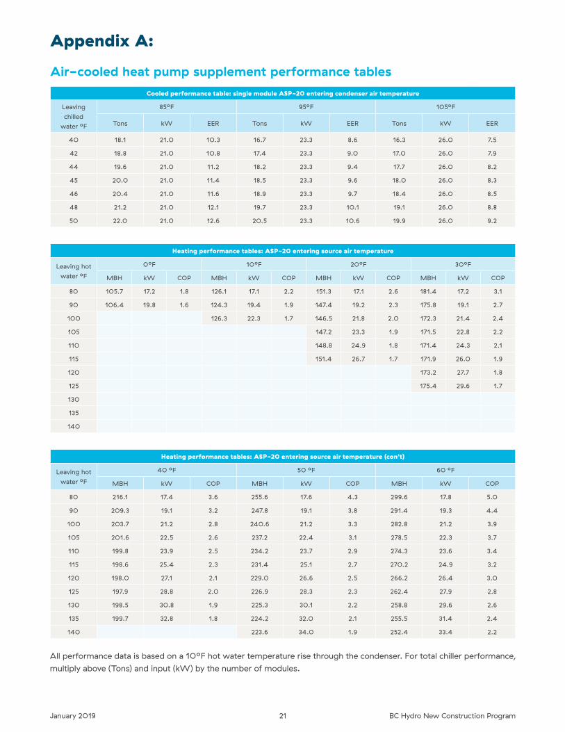
Appendix A:
Air-cooled heat pump supplement performance tablesCooled performance table: single module ASP-20 entering condenser air temperature
Leaving
chilled
water ºF
85ºF 95ºF 105ºF
Tons kW EER Tons kW EER Tons kW EER
40 18�1 21�0 10�3 16�7 23�3 8�6 16�3 26�0 7�5
42 18�8 21�0 10�8 17�4 23�3 9�0 17�0 26�0 7�9
44 19�6 21�0 11�2 18�2 23�3 9�4 17�7 26�0 8�2
45 20�0 21�0 11�4 18�5 23�3 9�6 18�0 26�0 8�3
46 20�4 21�0 11�6 18�9 23�3 9�7 18�4 26�0 8�5
48 21�2 21�0 12�1 19�7 23�3 10�1 19�1 26�0 8�8
50 22�0 21�0 12�6 20�5 23�3 10�6 19�9 26�0 9�2
Heating performance tables: ASP-20 entering source air temperature
Leaving hot
water ºF
0ºF 10ºF 20ºF 30ºF
MBH kW COP MBH kW COP MBH kW COP MBH kW COP
80 105�7 17�2 1�8 126�1 17�1 2�2 151�3 17�1 2�6 181�4 17�2 3�1
90 106�4 19�8 1�6 124�3 19�4 1�9 147�4 19�2 2�3 175�8 19�1 2�7
100 126�3 22�3 1�7 146�5 21�8 2�0 172�3 21�4 2�4
105 147�2 23�3 1�9 171�5 22�8 2�2
110 148�8 24�9 1�8 171�4 24�3 2�1
115 151�4 26�7 1�7 171�9 26�0 1�9
120 173�2 27�7 1�8
125 175�4 29�6 1�7
130
135
140
Heating performance tables: ASP-20 entering source air temperature (con’t)
Leaving hot
water ºF
40 ºF 50 ºF 60 ºF
MBH kW COP MBH kW COP MBH kW COP
80 216�1 17�4 3�6 255�6 17�6 4�3 299�6 17�8 5�0
90 209�3 19�1 3�2 247�8 19�1 3�8 291�4 19�3 4�4
100 203�7 21�2 2�8 240�6 21�2 3�3 282�8 21�2 3�9
105 201�6 22�5 2�6 237�2 22�4 3�1 278�5 22�3 3�7
110 199�8 23�9 2�5 234�2 23�7 2�9 274�3 23�6 3�4
115 198�6 25�4 2�3 231�4 25�1 2�7 270�2 24�9 3�2
120 198�0 27�1 2�1 229�0 26�6 2�5 266�2 26�4 3�0
125 197�9 28�8 2�0 226�9 28�3 2�3 262�4 27�9 2�8
130 198�5 30�8 1�9 225�3 30�1 2�2 258�8 29�6 2�6
135 199�7 32�8 1�8 224�2 32�0 2�1 255�5 31�4 2�4
140 223�6 34�0 1�9 252�4 33�4 2�2
All performance data is based on a 10ºF hot water temperature rise through the condenser� For total chiller performance,
multiply above (Tons) and input (kW) by the number of modules�
22January 2019 BC Hydro New Construction Program
Appendix B:
Lighting annual hours of operations (for non-dwelling units spaces)
Corridor/ lobby for elevator
Washroom Locker room Stairway
3880 3100 3100 2910
3880 3100 3100 2910
2930 2340 2340 2200
5220 4180 4180 3920
5220 4180 4180 3920
5220 4180 4180 3920
8760 2380 2380 5260
2950 2360 2360 2660
8760 7010 7010 6570
2950 2360 2360 2660
2930 2340 2340 2200
8760 7010 7010 6570
8760 1630 1630 6570
3880 3100 3100 3490
3880 3100 3100 3490
8760 1630 1630 6570
2980 1740 1740 2680
8760 7010 7010 4820
3880 3100 3100 3490
2930 2340 2340 2200
8760 7010 7010 5260
8760 2340 2340 5260
2980 830 830 2680
8760 7010 7010 6570
3880 3100 3100 2910
2180 1740 1740 1960
3880 3100 3100 3490
2930 2340 2340 2200
5220 4180 4180 4700
3370 2700 2700 2530
8760 7010 7010 7880
2830 2260 2260 2120
3880 3100 3100 2910
Building area type Annual hours
Automotive facility 3210
Convention centre 3530
Courthouse 2820
Dining: bar lounge/ leisure 4740
Dining: cafeteria/ fast food 4590
Dining: family 4750
Dormitory 3870
Exercise centre 2820
Fire station 5880
Gymnasium 2870
Health-care clinic 3290
Hospital 4720
Hotel 3310
Library 3610
Manufacturing facility 3760
Motel 3620
Motion picture theatre 2620
Multi-unit residential building 6210
Museum 3500
Office 2870
Parking garage 5760
Penitentiary 4450
Performing arts theatre 1940
Police station 4100
Post office 3140
Religious building 2350
Retail area 3750
School/ university 2580
Sports arena 4170
Town hall 3040
Transportation 5190
Warehouse 2830
Workshop 3580
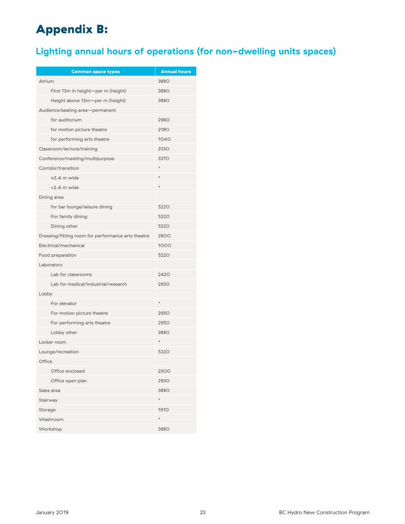
23January 2019 BC Hydro New Construction Program
Common space types Annual hours
Atrium 3880
First 13m in height—per m (height) 3880
Height above 13m—per m (height) 3880
Audience/seating area—permanent
for auditorium 2980
for motion picture theatre 2180
for performing arts theatre 1040
Classroom/lecture/training 2330
Conference/meeting/multipurpose 3370
Corridor/transition *
≥2�4 m wide *
<2�4 m wide *
Dining area
for bar lounge/leisure dining 5220
For family dining 5220
Dining other 5220
Dressing/fitting room for performance arts theatre 2800
Electrical/mechanical 1000
Food preparation 5220
Laboratory
Lab for classrooms 2420
Lab for medical/Industrial/research 2930
Lobby
For elevator *
For motion picture theatre 2950
For performing arts theatre 2950
Lobby other 3880
Locker room *
Lounge/recreation 5220
Office
Office enclosed 2300
Office open plan 2930
Sales area 3880
Stairway *
Storage 1910
Washroom *
Workshop 3880
Appendix B:
Lighting annual hours of operations (for non-dwelling units spaces)
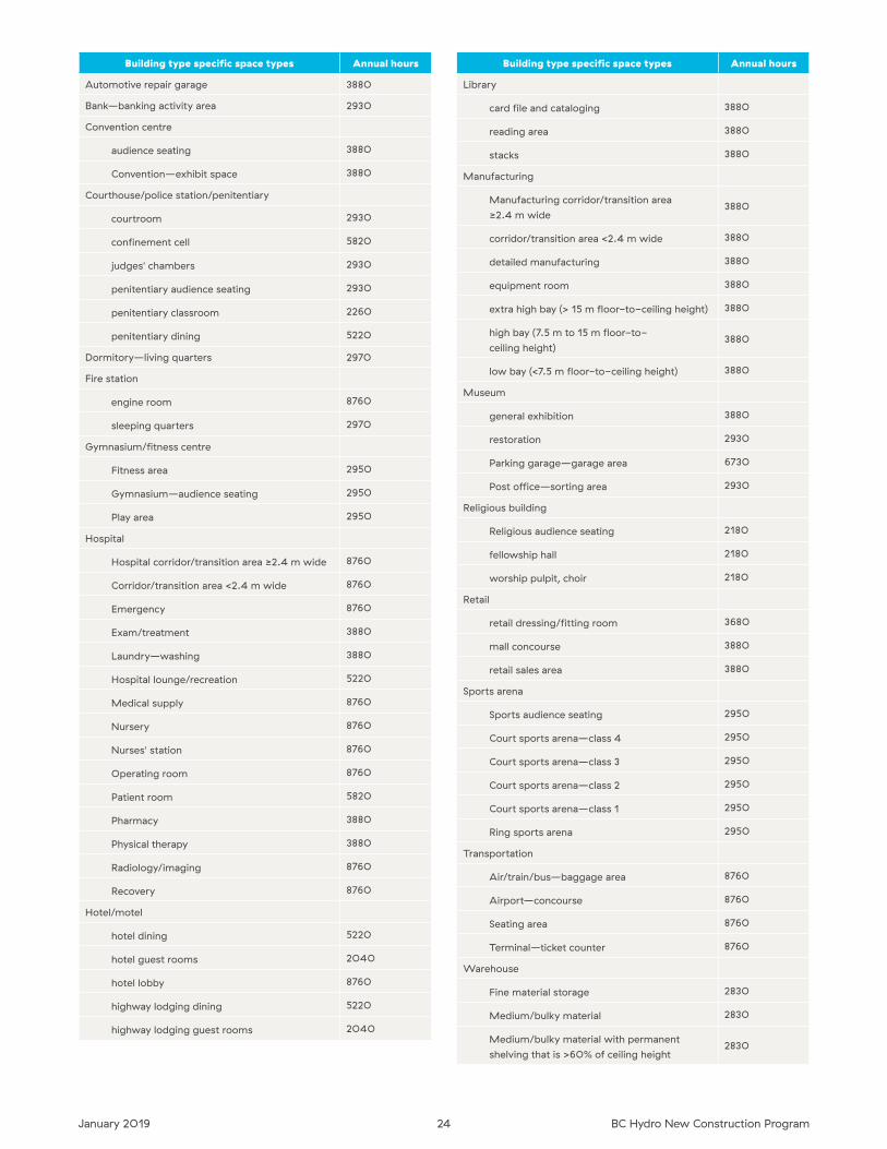
24January 2019 BC Hydro New Construction Program
Building type specific space types Annual hours
Library
card file and cataloging 3880
reading area 3880
stacks 3880
Manufacturing
Manufacturing corridor/transition area
≥2�4 m wide3880
corridor/transition area <2�4 m wide 3880
detailed manufacturing 3880
equipment room 3880
extra high bay (> 15 m floor-to-ceiling height) 3880
high bay (7�5 m to 15 m floor-to-
ceiling height)3880
low bay (<7�5 m floor-to-ceiling height) 3880
Museum
general exhibition 3880
restoration 2930
Parking garage—garage area 6730
Post office—sorting area 2930
Religious building
Religious audience seating 2180
fellowship hall 2180
worship pulpit, choir 2180
Retail
retail dressing/fitting room 3680
mall concourse 3880
retail sales area 3880
Sports arena
Sports audience seating 2950
Court sports arena—class 4 2950
Court sports arena—class 3 2950
Court sports arena—class 2 2950
Court sports arena—class 1 2950
Ring sports arena 2950
Transportation
Air/train/bus—baggage area 8760
Airport—concourse 8760
Seating area 8760
Terminal—ticket counter 8760
Warehouse
Fine material storage 2830
Medium/bulky material 2830
Medium/bulky material with permanent
shelving that is >60% of ceiling height 2830
Building type specific space types Annual hours
Automotive repair garage 3880
Bank—banking activity area 2930
Convention centre
audience seating 3880
Convention—exhibit space 3880
Courthouse/police station/penitentiary
courtroom 2930
confinement cell 5820
judges' chambers 2930
penitentiary audience seating 2930
penitentiary classroom 2260
penitentiary dining 5220
Dormitory—living quarters 2970
Fire station
engine room 8760
sleeping quarters 2970
Gymnasium/fitness centre
Fitness area 2950
Gymnasium—audience seating 2950
Play area 2950
Hospital
Hospital corridor/transition area ≥2�4 m wide 8760
Corridor/transition area <2�4 m wide 8760
Emergency 8760
Exam/treatment 3880
Laundry—washing 3880
Hospital lounge/recreation 5220
Medical supply 8760
Nursery 8760
Nurses' station 8760
Operating room 8760
Patient room 5820
Pharmacy 3880
Physical therapy 3880
Radiology/imaging 8760
Recovery 8760
Hotel/motel
hotel dining 5220
hotel guest rooms 2040
hotel lobby 8760
highway lodging dining 5220
highway lodging guest rooms 2040

BCH19-061
For more information on our New Construction Program, call us today.
604 522 4713 Lower Mainland
1 866 522 4713 elsewhere in B.C.
bchydro.com/construction