Embed Size (px)
Citation preview
New Architecture of Direct RF Sampling for Avionic Systems applied to VOR and ILS
Anh-Quang Nguyen, Alireza Avakh Kisomi, René Jr. Landry Laboratory of Space Technologies, Embedded Systems, Navigation and Avionic (LASSENA)
École de Technologie Supérieure, (ETS), Department of Electrical Engineering, Montréal, QC, CANADA [email protected], [email protected], [email protected]
Abstract—In the aerospace industry, there is an increased demand for a new kind of avionic architecture, in order to reduce cost, weight, number of components, certification, installation and maintenance complexity, while improving the security, compatibility and RF efficiency. The key solution to achieve this goal is to integrate multiple avionic systems, apply new signal processing and RF capabilities. A generalized and reconfigurable architecture of Multi-Mode Receiver (MMR) with integrated and modularised structure based on Direct RF Sampling (DRFS) and Software Defined Radio (SDR) is presented in this paper for avionic applications. The proposed architecture is composed of a DRFS digital receiver integrated within a SDR software modules. DRFS technology is adopted in the digital receiver, which consists of Pre-selection Filters and Field Programmable Gate Arrays (FPGA) to provide flexible compatibility for diverse modulation modes and various RF/IF frequency bands. By employing the concept of DRFS/SDR, distinct procedures for different avionic purposes, such as Very High Frequency Omnidirectional Range (VOR) and Instrument Landing System (ILS), can be achieved in the same hardware platform. Notably, this proposed architecture has the potential to be reconfigured and improved in several ways without any hardware change to accommodate new features and signal capabilities. As per experimental validation phase, an MMR integrated system for VOR and ILS receivers has been designed and implemented. Test results have illustrated that the implementation feasibility of multi-mode DRFS avionic receivers is beneficial and efficient using the proposed architecture. Moreover, the benefits obtained from this new approach are not only covering miniaturization, lightweight, and low power consumption but is also promising to overreach the equivalent commercial systems in the future.
Keywords—Avionic, DRFS, SDR, MMR, IMA, VHF, VOR, ILS
I. INTRODUCTION
Software Defined Radio (SDR) has interested researchers and developers for last decades and has been proven as a promising approach for various applications in navigation, telecommunication and other wireless applications. SDR with new developments in RF integrated circuit (IC) and Analog to Digital Converter (ADC) are not only pushing further the current performance of RF transceivers, but also introducing alternative promising architectures, such as DRFS, to overcome existing limitations and allowing new capabilities. The main difference between the DRFS receiver architecture and actual receiver versions is that, it removes IF/LO mixer stages, which is consequently reducing the total amount of analog components with the capabilities to acquire a wide RF band in digital. This
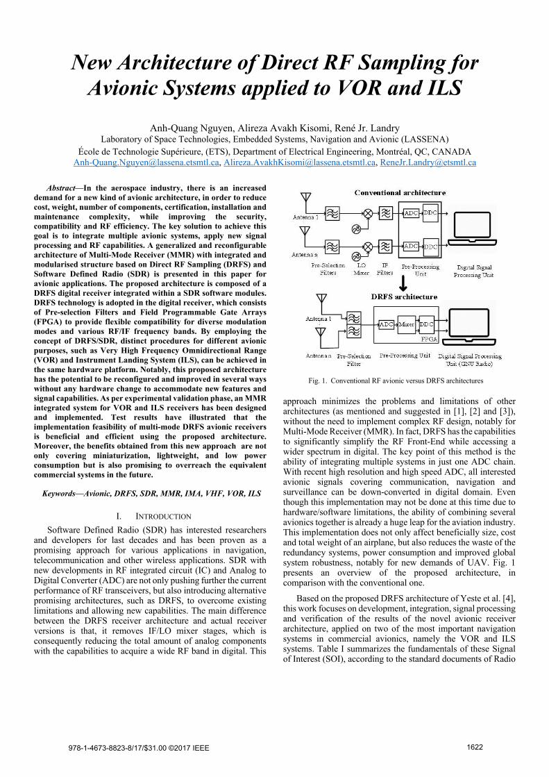
approach minimizes the problems and limitations of other architectures (as mentioned and suggested in [1], [2] and [3]), without the need to implement complex RF design, notably for Multi-Mode Receiver (MMR). In fact, DRFS has the capabilities to significantly simplify the RF Front-End while accessing a wider spectrum in digital. The key point of this method is the ability of integrating multiple systems in just one ADC chain. With recent high resolution and high speed ADC, all interested avionic signals covering communication, navigation and surveillance can be down-converted in digital domain. Even though this implementation may not be done at this time due to hardware/software limitations, the ability of combining several avionics together is already a huge leap for the aviation industry. This implementation does not only affect beneficially size, cost and total weight of an airplane, but also reduces the waste of the redundancy systems, power consumption and improved global system robustness, notably for new demands of UAV. Fig. 1 presents an overview of the proposed architecture, in comparison with the conventional one.
Based on the proposed DRFS architecture of Yeste et al. [4], this work focuses on development, integration, signal processing and verification of the results of the novel avionic receiver architecture, applied on two of the most important navigation systems in commercial avionics, namely the VOR and ILS systems. Table I summarizes the fundamentals of these Signal of Interest (SOI), according to the standard documents of Radio
Fig. 1. Conventional RF avionic versus DRFS architectures
978-1-4673-8823-8/17/$31.00 ©2017 IEEE 1622

Technical Commission for Aeronautical (RTCA) [5–7]. Among the requirements mentioned for Minimum Operational Performance Standards (MOPS) for airborne receivers, the experimental results presented in this paper concentrate on the basics, yet crucial requirements, such as sensitivity, accuracy, latency and maximum input power.
This paper is organized as follow. After overviewing the DRFS fundamental theories and related previous researches, the section II will provide full details of the developed DRFS architecture in System Generator level. The section III will present the VOR and ILS implementation with laboratory test results and detail performance analysis of the proposed architecture. The conclusion will provide a summary of the proposed novel architecture, and suggests some solutions for current limitations allowing its expansion to numerous other avionic signal.
II. DRFS FUNDAMENTALS AND PROPOSED ARCHITECTURE
A. Direct Radio Frequency Sampling (DRFS)
DRFS operates based on bandpass sampling (sub-sampling) theory. A normal sampling technique requires the sampling rate of at least twice the frequency of the Signal of Interest (SOI), while sub-sampling aims at the alias of that signal in the first Nyquist zone, and therefore asks for a much lower rate. Using one of the most fundamental knowledge in sampling technique, as mentioned by R. G. Lyon in [8], “When sampling at a rate of fs, if k is any positive/negative integer, one cannot distinguish between the sampled values of a sin wave of f0 Hz and a sin wave of (f0+kfs) Hz”. With this statement, DRFS offers the chance to convert a GHz analog signal into digital values with just MHz sampling rate. The alias created by the ADC after the sampling can be processed in digital domain to extract the information carried in the SOI. With latest wideband ADCs, the passband in the first zone can be several hundreds of MHz, wide enough to access several avionic SOIs in different bands at the same time. Fig. 2 illustrates this general concept with the spectrum folding effect and the aliases in the first Nyquist zone. The ADC output signal is then mixed by the digital Local Oscillator (LO) mixer
in the FPGA, selecting the SOI and down-sampling them for further signal processing.
The major limitation of this technique is called the ‘Bandpass Nyquist Sampling Theory’, indicating that fs must be at least twice the bandwidth of any SOI. The most important precaution with this approach is to avoid the signal overlapping within the Nyquist zone. This criterion can be overcome by using proper bandpass filters along with careful selection of the sampling frequency. The methods for determining the sampling frequency have been presented in [9] and generalized in [10].
Noticing the advantages of Direct RF Sampling compared to Heterodyne/Homodyne architecture, some pioneering researches have been done with positive results. An example for the application of DRFS can be found in the work of Lamontagne [11], also summarized in [12]. His study proves the possibility of using DRFS architecture for Global Navigation Satellite System (GNSS) without performance reduction. In fact and as mentioned by the author, it is important to note that the accuracy of the DRFS architecture is similar to some state-of-the-art commercial receivers and even better in some aspects.
In this paper, VHF avionics is studied using the Nutaq SDR PicoDigitizer250, with a 14 bit ADC (ADS62P49) running at 250 MSPS, a minimum SFDR at -82 dBFS (for 100-150 MHz and 300-350 MHz input signals) and full scale results in -35
TABLE I. MAIN CHARACTERISTICS OF VOR AND ILS SYSTEMS [5-7]
System Characteristics
VOR
Band of Frequency 111.975 MHz – 117.975 MHz
Spacing between channel 25 kHz
Signal in baseband Various signals at 1020 Hz, 30 Hz, 9960 Hz, etc.
Minimum Performance Requirements for Receiver
With input from -93 to -27 dBm, the error must be < 3 degrees at least 95 % of the samples
ILS
Band of Frequency - Localizer (LOC): 108.1 MHz – 111.95 MHz - Glide Slope (G/S): 329.15 MHz – 335.0 MHz - Marker Beacon: 75 MHz
Bandwidth ≤1500 Hz
Signal in baseband 90 Hz and 150 Hz for both LOC and G/S, 1020 for LOC
Minimum Performance Requirements for Receiver
With input from -87 to -33 dBm, the error must be < 0.00455 Difference in Depth of Modulation (DDM) at least 95% of the samples (LOC) With input from -77 to -33 dBm, the error must be < 0.01183 DDM at least 95% of the samples (G/S)
Fig. 2. Bandpass sampling concept for DRFS application
978-1-4673-8823-8/17/$31.00 ©2017 IEEE 1623
dBm [13-14]. As other SDRs, PicoDigitizer offers FPGA approach, increasing the adaptability research development and system reconfigurability. The ADC sampling frequency offers a maximum bandwidth of 125 MHz; however, in order to reduce the stress on the ADC and reduce power consumption, a lower sampling rate is used. In [4], two methods of applying DRFS for VHF avionic system are proposed; dynamic and static. The dynamic version offers a small sampling frequency (14.454 MHz), but brings its own limitations. With dynamic approach, the architecture will require very high Q filter to make sure that there would be no collapse with other RF signals. In addition, a very selective system such as this will reduce the adaptability of the proposed architecture, against one of selected objectives. The static version would be a more flexible and easier option, suggesting the minimum sampling frequency of 137 MHz for this application. However, this value is too close to the upper frequency of another system in the VHF avionic band, namely the Aircraft Communication Addressing and Reporting System (ACARS) (136.9 MHz). Therefore and after consideration, fs = 140 MHz is chosen, providing a 70 MHz bandwidth in the first Nyquist zone, wide enough to avoid the overlaps in the VHF avionics band.
B. Proposed DRFS architecture
The proposed architecture, as shown in the lower half of Fig. 1, consists of three subsystems: the Pre-Selection Filter, the Pre-Processing Unit (i.e. SDR) and the Main Processing Unit (MPU), which is fully compliant with actual IMA system. The
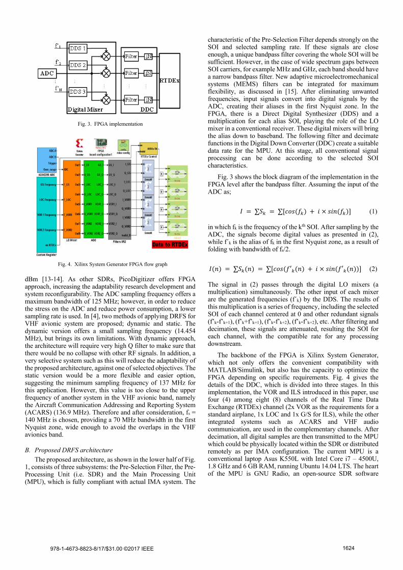
characteristic of the Pre-Selection Filter depends strongly on the SOI and selected sampling rate. If these signals are close enough, a unique bandpass filter covering the whole SOI will be sufficient. However, in the case of wide spectrum gaps between SOI carriers, for example MHz and GHz, each band should have a narrow bandpass filter. New adaptive microelectromechanical systems (MEMS) filters can be integrated for maximum flexibility, as discussed in [15]. After eliminating unwanted frequencies, input signals convert into digital signals by the ADC, creating their aliases in the first Nyquist zone. In the FPGA, there is a Direct Digital Synthesizer (DDS) and a multiplication for each alias SOI, playing the role of the LO mixer in a conventional receiver. These digital mixers will bring the alias down to baseband. The following filter and decimate functions in the Digital Down Converter (DDC) create a suitable data rate for the MPU. At this stage, all conventional signal processing can be done according to the selected SOI characteristics.
Fig. 3 shows the block diagram of the implementation in the FPGA level after the bandpass filter. Assuming the input of the ADC as;
� = ∑�� = ∑[���(��) + � × ���(��)] (1)
in which fk is the frequency of the kth SOI. After sampling by the ADC, the signals become digital values as presented in (2), while f´k is the alias of fk in the first Nyquist zone, as a result of folding with bandwidth of fs/2.
�(�) = ∑��(�) = ∑[���(�′�(�) + � × ���(�′�(�))] (2)
The signal in (2) passes through the digital LO mixers (a multiplication) simultaneously. The other input of each mixer are the generated frequencies (f´k) by the DDS. The results of this multiplication is a series of frequency, including the selected SOI of each channel centered at 0 and other redundant signals (f’k-f’k+1), (f’k+f’k+1), (f’k-f’k+2), (f’k-f’k+2), etc. After filtering and decimation, these signals are attenuated, resulting the SOI for each channel, with the compatible rate for any processing downstream.
The backbone of the FPGA is Xilinx System Generator, which not only offers the convenient compatibility with MATLAB/Simulink, but also has the capacity to optimize the FPGA depending on specific requirements. Fig. 4 gives the details of the DDC, which is divided into three stages. In this implementation, the VOR and ILS introduced in this paper, use four (4) among eight (8) channels of the Real Time Data Exchange (RTDEx) channel (2x VOR as the requirements for a standard airplane, 1x LOC and 1x G/S for ILS), while the other integrated systems such as ACARS and VHF audio communication, are used in the complementary channels. After decimation, all digital samples are then transmitted to the MPU which could be physically located within the SDR or distributed remotely as per IMA configuration. The current MPU is a conventional laptop Asus K550L with Intel Core i7 – 4500U, 1.8 GHz and 6 GB RAM, running Ubuntu 14.04 LTS. The heart of the MPU is GNU Radio, an open-source SDR software
Fig. 4. Xilinx System Generator FPGA flow graph
Fig. 3. FPGA implementation
978-1-4673-8823-8/17/$31.00 ©2017 IEEE 1624
development toolkit used in various digital signal processing researches.
C. GNU Radio signal processing
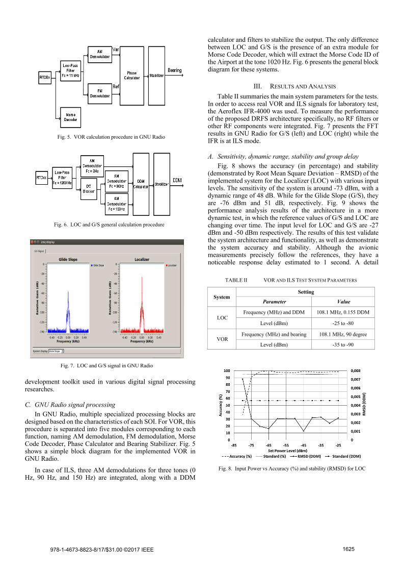
In GNU Radio, multiple specialized processing blocks are designed based on the characteristics of each SOI. For VOR, this procedure is separated into five modules corresponding to each function, naming AM demodulation, FM demodulation, Morse Code Decoder, Phase Calculator and Bearing Stabilizer. Fig. 5 shows a simple block diagram for the implemented VOR in GNU Radio.
In case of ILS, three AM demodulations for three tones (0 Hz, 90 Hz, and 150 Hz) are integrated, along with a DDM
calculator and filters to stabilize the output. The only difference between LOC and G/S is the presence of an extra module for Morse Code Decoder, which will extract the Morse Code ID of the Airport at the tone 1020 Hz. Fig. 6 presents the general block diagram for these systems.
III. RESULTS AND ANALYSIS
Table II summaries the main system parameters for the tests. In order to access real VOR and ILS signals for laboratory test, the Aeroflex IFR-4000 was used. To measure the performance of the proposed DRFS architecture specifically, no RF filters or other RF components were integrated. Fig. 7 presents the FFT results in GNU Radio for G/S (left) and LOC (right) while the IFR is at ILS mode.
A. Sensitivity, dynamic range, stability and group delay
Fig. 8 shows the accuracy (in percentage) and stability (demonstrated by Root Mean Square Deviation – RMSD) of the implemented system for the Localizer (LOC) with various input levels. The sensitivity of the system is around -73 dBm, with a dynamic range of 48 dB. While for the Glide Slope (G/S), they are -76 dBm and 51 dB, respectively. Fig. 9 shows the performance analysis results of the architecture in a more dynamic test, in which the reference values of G/S and LOC are changing over time. The input level for LOC and G/S are -27 dBm and -50 dBm respectively. The results of this test validate the system architecture and functionality, as well as demonstrate the system accuracy and stability. Although the avionic measurements precisely follow the references, they have a noticeable response delay estimated to 1 second. A detail
TABLE II VOR AND ILS TEST SYSTEM PARAMETERS
System Setting
Parameter Value
LOC Frequency (MHz) and DDM 108.1 MHz, 0.155 DDM
Level (dBm) -25 to -80
VOR Frequency (MHz) and bearing 108.1 MHz, 90 degree
Level (dBm) -35 to -90
Fig. 8. Input Power vs Accuracy (%) and stability (RMSD) for LOC
Fig. 6. LOC and G/S general calculation procedure
Fig. 5. VOR calculation procedure in GNU Radio
Fig. 7. LOC and G/S signal in GNU Radio
978-1-4673-8823-8/17/$31.00 ©2017 IEEE 1625
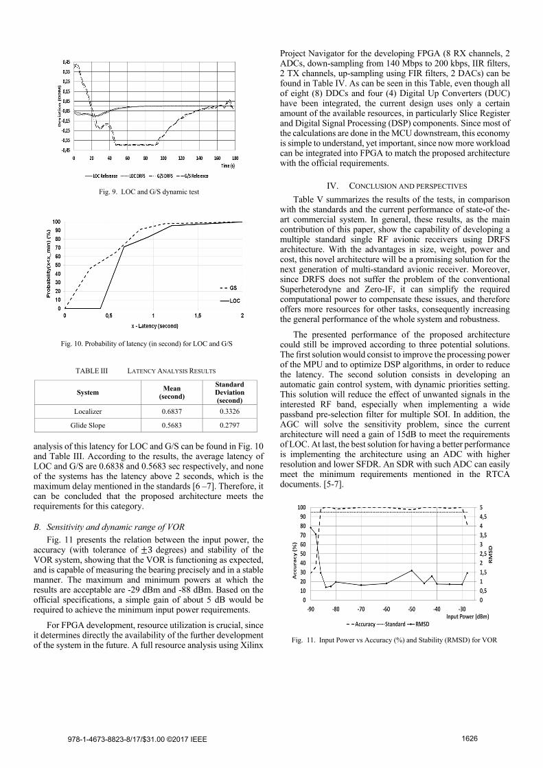
analysis of this latency for LOC and G/S can be found in Fig. 10 and Table III. According to the results, the average latency of LOC and G/S are 0.6838 and 0.5683 sec respectively, and none of the systems has the latency above 2 seconds, which is the maximum delay mentioned in the standards [6 –7]. Therefore, it can be concluded that the proposed architecture meets the requirements for this category.
B. Sensitivity and dynamic range of VOR
Fig. 11 presents the relation between the input power, the accuracy (with tolerance of ±3 degrees) and stability of the VOR system, showing that the VOR is functioning as expected, and is capable of measuring the bearing precisely and in a stable manner. The maximum and minimum powers at which the results are acceptable are -29 dBm and -88 dBm. Based on the official specifications, a simple gain of about 5 dB would be required to achieve the minimum input power requirements.
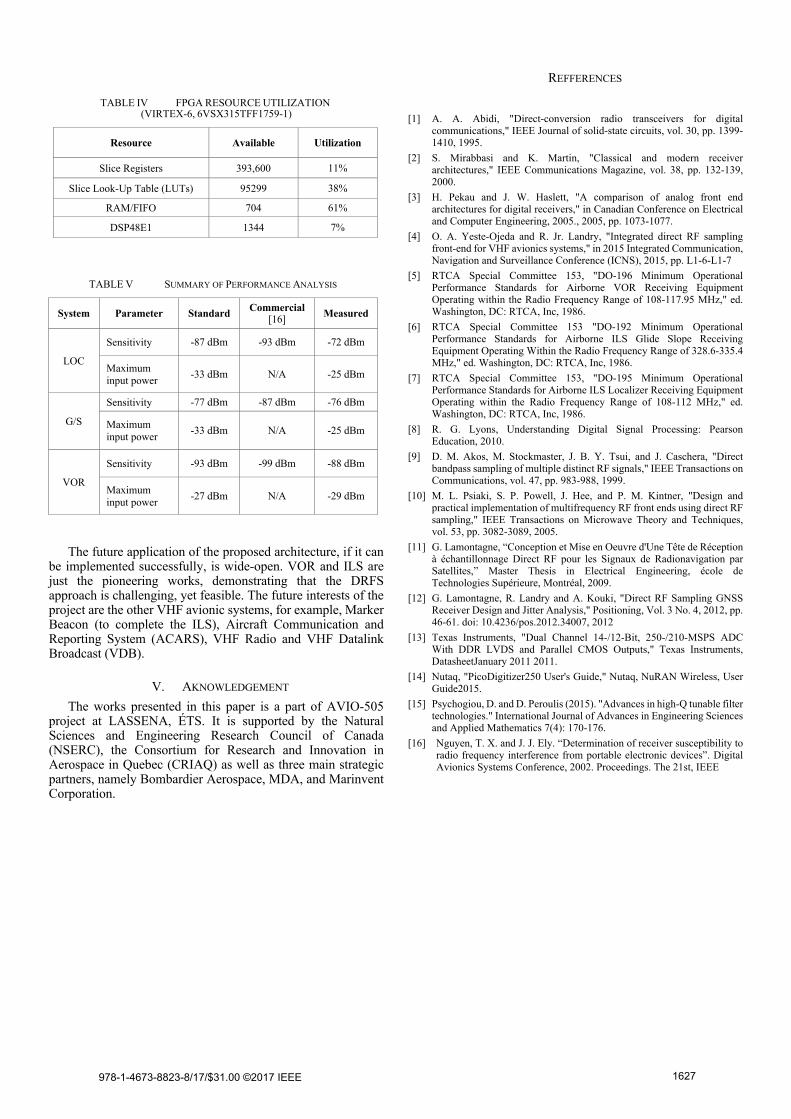
For FPGA development, resource utilization is crucial, since it determines directly the availability of the further development of the system in the future. A full resource analysis using Xilinx
Project Navigator for the developing FPGA (8 RX channels, 2 ADCs, down-sampling from 140 Mbps to 200 kbps, IIR filters, 2 TX channels, up-sampling using FIR filters, 2 DACs) can be found in Table IV. As can be seen in this Table, even though all of eight (8) DDCs and four (4) Digital Up Converters (DUC) have been integrated, the current design uses only a certain amount of the available resources, in particularly Slice Register and Digital Signal Processing (DSP) components. Since most of the calculations are done in the MCU downstream, this economy is simple to understand, yet important, since now more workload can be integrated into FPGA to match the proposed architecture with the official requirements.
IV. CONCLUSION AND PERSPECTIVES
Table V summarizes the results of the tests, in comparison with the standards and the current performance of state-of the-art commercial system. In general, these results, as the main contribution of this paper, show the capability of developing a multiple standard single RF avionic receivers using DRFS architecture. With the advantages in size, weight, power and cost, this novel architecture will be a promising solution for the next generation of multi-standard avionic receiver. Moreover, since DRFS does not suffer the problem of the conventional Superheterodyne and Zero-IF, it can simplify the required computational power to compensate these issues, and therefore offers more resources for other tasks, consequently increasing the general performance of the whole system and robustness.
The presented performance of the proposed architecture could still be improved according to three potential solutions. The first solution would consist to improve the processing power of the MPU and to optimize DSP algorithms, in order to reduce the latency. The second solution consists in developing an automatic gain control system, with dynamic priorities setting. This solution will reduce the effect of unwanted signals in the interested RF band, especially when implementing a wide passband pre-selection filter for multiple SOI. In addition, the AGC will solve the sensitivity problem, since the current architecture will need a gain of 15dB to meet the requirements of LOC. At last, the best solution for having a better performance is implementing the architecture using an ADC with higher resolution and lower SFDR. An SDR with such ADC can easily meet the minimum requirements mentioned in the RTCA documents. [5-7].
Fig. 9. LOC and G/S dynamic test
Fig. 10. Probability of latency (in second) for LOC and G/S
Fig. 11. Input Power vs Accuracy (%) and Stability (RMSD) for VOR
TABLE III LATENCY ANALYSIS RESULTS
System Mean
(second)
Standard Deviation (second)
Localizer 0.6837 0.3326
Glide Slope 0.5683 0.2797
978-1-4673-8823-8/17/$31.00 ©2017 IEEE 1626
The future application of the proposed architecture, if it can be implemented successfully, is wide-open. VOR and ILS are just the pioneering works, demonstrating that the DRFS approach is challenging, yet feasible. The future interests of the project are the other VHF avionic systems, for example, Marker Beacon (to complete the ILS), Aircraft Communication and Reporting System (ACARS), VHF Radio and VHF Datalink Broadcast (VDB).
V. AKNOWLEDGEMENT
The works presented in this paper is a part of AVIO-505 project at LASSENA, ÉTS. It is supported by the Natural Sciences and Engineering Research Council of Canada (NSERC), the Consortium for Research and Innovation in Aerospace in Quebec (CRIAQ) as well as three main strategic partners, namely Bombardier Aerospace, MDA, and Marinvent Corporation.
REFFERENCES
[1] A. A. Abidi, "Direct-conversion radio transceivers for digital communications," IEEE Journal of solid-state circuits, vol. 30, pp. 1399-1410, 1995.
[2] S. Mirabbasi and K. Martin, "Classical and modern receiver architectures," IEEE Communications Magazine, vol. 38, pp. 132-139, 2000.
[3] H. Pekau and J. W. Haslett, "A comparison of analog front end architectures for digital receivers," in Canadian Conference on Electrical and Computer Engineering, 2005., 2005, pp. 1073-1077.
[4] O. A. Yeste-Ojeda and R. Jr. Landry, "Integrated direct RF sampling front-end for VHF avionics systems," in 2015 Integrated Communication, Navigation and Surveillance Conference (ICNS), 2015, pp. L1-6-L1-7
[5] RTCA Special Committee 153, "DO-196 Minimum Operational Performance Standards for Airborne VOR Receiving Equipment Operating within the Radio Frequency Range of 108-117.95 MHz," ed. Washington, DC: RTCA, Inc, 1986.
[6] RTCA Special Committee 153 "DO-192 Minimum Operational Performance Standards for Airborne ILS Glide Slope Receiving Equipment Operating Within the Radio Frequency Range of 328.6-335.4 MHz," ed. Washington, DC: RTCA, Inc, 1986.
[7] RTCA Special Committee 153, "DO-195 Minimum Operational Performance Standards for Airborne ILS Localizer Receiving Equipment Operating within the Radio Frequency Range of 108-112 MHz," ed. Washington, DC: RTCA, Inc, 1986.
[8] R. G. Lyons, Understanding Digital Signal Processing: Pearson Education, 2010.
[9] D. M. Akos, M. Stockmaster, J. B. Y. Tsui, and J. Caschera, "Direct bandpass sampling of multiple distinct RF signals," IEEE Transactions on Communications, vol. 47, pp. 983-988, 1999.
[10] M. L. Psiaki, S. P. Powell, J. Hee, and P. M. Kintner, "Design and practical implementation of multifrequency RF front ends using direct RF sampling," IEEE Transactions on Microwave Theory and Techniques, vol. 53, pp. 3082-3089, 2005.
[11] G. Lamontagne, “Conception et Mise en Oeuvre d'Une Tête de Réception à échantillonnage Direct RF pour les Signaux de Radionavigation par Satellites,” Master Thesis in Electrical Engineering, école de Technologies Supérieure, Montréal, 2009.
[12] G. Lamontagne, R. Landry and A. Kouki, "Direct RF Sampling GNSS Receiver Design and Jitter Analysis," Positioning, Vol. 3 No. 4, 2012, pp. 46-61. doi: 10.4236/pos.2012.34007, 2012
[13] Texas Instruments, "Dual Channel 14-/12-Bit, 250-/210-MSPS ADC With DDR LVDS and Parallel CMOS Outputs," Texas Instruments, DatasheetJanuary 2011 2011.
[14] Nutaq, "PicoDigitizer250 User's Guide," Nutaq, NuRAN Wireless, User Guide2015.
[15] Psychogiou, D. and D. Peroulis (2015). "Advances in high-Q tunable filter technologies." International Journal of Advances in Engineering Sciences and Applied Mathematics 7(4): 170-176.
[16] Nguyen, T. X. and J. J. Ely. “Determination of receiver susceptibility to radio frequency interference from portable electronic devices”. Digital Avionics Systems Conference, 2002. Proceedings. The 21st, IEEE
TABLE IV FPGA RESOURCE UTILIZATION (VIRTEX-6, 6VSX315TFF1759-1)
Resource Available Utilization
Slice Registers 393,600 11%
Slice Look-Up Table (LUTs) 95299 38%
RAM/FIFO 704 61%
DSP48E1 1344 7%
TABLE V SUMMARY OF PERFORMANCE ANALYSIS
System Parameter Standard Commercial
[16] Measured
LOC
Sensitivity -87 dBm -93 dBm -72 dBm
Maximum input power
-33 dBm N/A -25 dBm
G/S
Sensitivity -77 dBm -87 dBm -76 dBm
Maximum input power
-33 dBm N/A -25 dBm
VOR
Sensitivity -93 dBm -99 dBm -88 dBm
Maximum input power
-27 dBm N/A -29 dBm
978-1-4673-8823-8/17/$31.00 ©2017 IEEE 1627