Embed Size (px)
Citation preview

Neuvokas Corporation Design and
Installation Manual for GatorBar®
Revision 01 – Released 2021-03-12
Document # D-IM-GatorBar
Questions or Comments can be addressed to Neuvokas Corporation with contact
information listed below
Neuvokas Corporation
PO Box 220
3206 #6 Road
Ahmeek, MI 49901
906-934-2661
Company and Product websites
www.gatorbar.com
www.neuvokascorp.com

Contents 1.0 Introduction ............................................................................................................................................ 3
2.0 GatorBar® FRP Rebar by Neuvokas ......................................................................................................... 3
2.1 FRP Composite Description ................................................................................................................. 3
2.2 GatorBar® Experimental Properties .................................................................................................... 3
3.0 Installation Instructions .......................................................................................................................... 4
4.0 General Design Considerations ............................................................................................................... 5
4.1 FRP Creep Rupture and Fatigue .......................................................................................................... 5
4.2 Concrete Member Cross-Section ........................................................................................................ 5
4.3 FRP Bar Arrangement .......................................................................................................................... 5
5.0 Design Manual ........................................................................................................................................ 5
5.1 Flexural Reinforcement: ...................................................................................................................... 6
5.2 Notation .............................................................................................................................................. 6
5.3 Reinforcement in Columns ................................................................................................................. 7
5.3.1 Scope ............................................................................................................................................ 7
5.3.2 General ......................................................................................................................................... 7
5.3.3 Design Limits ................................................................................................................................ 8
5.3.4 Required Strength ........................................................................................................................ 8
5.3.5 Design strength ............................................................................................................................ 8
5.3.5.2 Axial force and moment ............................................................................................................ 8
5.3.5.3 Shear ......................................................................................................................................... 8
5.3.5.4 Torsion ..................................................................................................................................... 10
5.3.6 Reinforcement limits .................................................................................................................. 11
5.3.7 Reinforcement detailing ............................................................................................................ 11
5.4 Walls .................................................................................................................................................. 13
5.4.1 – Scope ....................................................................................................................................... 13
5.4.2 – General Information ................................................................................................................ 14
5.4.3 – Design Limits ........................................................................................................................... 14
5.4.4 – Required Strength ................................................................................................................... 15
5.4.5 – Design Strength ....................................................................................................................... 16
5.5 Flatwork (slab-on-grade) .................................................................................................................. 20
5.6 Footers .............................................................................................................................................. 21

1.0 Introduction The purpose of this design and installation manual is to provide design guidelines as part of ESR-4526
per AC454. This document contains design equations, reference to other design tools, multiple design
examples, and installation instructions/guidelines.
This document has been prepared using the following documents.
• ACI Committee 318, “Building Code Requirements for Structural Concrete (ACI 318-14) and
Commentary (318R- -14),” American Concrete Institute, Farmington Hills, MI, 2011
• ACI Committee 440, “Guide for the Design and Construction of Structural Concrete Reinforced
with FRP Bars
• “Reinforced Concrete with FRP Bars, Mechanics and Design”, Nanni, Antonio, Antonio De Luca,
and Hany Jawaheri Zadeh, 2014
2.0 GatorBar® FRP Rebar by Neuvokas
2.1 FRP Composite Description GatorBar® by Neuvokas is a glass fiber reinforced composite rebar that is composed of fiber embedded
in a polymer resin. Across the industry these products are known as glass fiber reinforced polymer
(GFRP) rebar. At the date of this design manual release GatorBar can be purchased in #3 (0.375 inch)
and #4 (0.5 inch) sizes but the ICC-ES evaluation report only covers the #3 rebar size.
2.2 GatorBar® Experimental Properties The following values have been tested by a certified third party (University of Miami) and a copy of this
report is available upon request. Sampling of test specimens was completed per ICC AC85 and ASTM
D7957 requirements. The quantity of specimens for each experimental value were completed following
ASTM D7957. Guaranteed properties are equal to the defined ACI 440 nomenclature. It should be
noted that the tensile behavior of GFRP bars is characterized by a linear elastic stress-strain relationship
until failure.
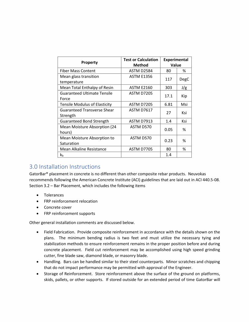
Property Test or Calculation
Method Experimental
Value
Fiber Mass Content ASTM D2584 80 %
Mean glass transition temperature
ASTM E1356 117 DegC
Mean Total Enthalpy of Resin ASTM E2160 303 J/g
Guaranteed Ultimate Tensile Force
ASTM D7205 17.1 Kip
Tensile Modulus of Elasticity ASTM D7205 6.81 Msi
Guaranteed Transverse Shear Strength
ASTM D7617 27 Ksi
Guaranteed Bond Strength ASTM D7913 1.4 Ksi
Mean Moisture Absorption (24 hours)
ASTM D570 0.05 %
Mean Moisture Absorption to Saturation
ASTM D570 0.23 %
Mean Alkaline Resistance ASTM D7705 80 %
kb 1.4
3.0 Installation Instructions GatorBar® placement in concrete is no different than other composite rebar products. Neuvokas
recommends following the American Concrete Institute (ACI) guidelines that are laid out in ACI 440.5-08.
Section 3.2 – Bar Placement, which includes the following items
• Tolerances
• FRP reinforcement relocation
• Concrete cover
• FRP reinforcement supports
Other general installation comments are discussed below.
• Field Fabrication. Provide composite reinforcement in accordance with the details shown on the
plans. The minimum bending radius is two feet and must utilize the necessary tying and
stabilization methods to ensure reinforcement remains in the proper position before and during
concrete placement. Field cut reinforcement may be accomplished using high speed grinding
cutter, fine blade saw, diamond blade, or masonry blade.
• Handling. Bars can be handled similar to their steel counterparts. Minor scratches and chipping
that do not impact performance may be permitted with approval of the Engineer.
• Storage of Reinforcement. Store reinforcement above the surface of the ground on platforms,
skids, pallets, or other supports. If stored outside for an extended period of time GatorBar will

yellow and it can be covered if desired. Overall strength is not affected by this yellowing and
GatorBar does not need to be covered.
• Placing and Fastening. Place all reinforcement within the tolerances recommended in the CRSI
"Manual of Standard Practice" unless otherwise specified in the contract documents. Secure
reinforcement firmly with mechanical fasteners during the placing and setting of the concrete.
Suspend concrete placement and take corrective action if it is observed that the reinforcement is
not adequately supported or tied to resist settlement, floating upward, or movement in any
direction during concrete placement.
• Ties and Supports. It is recommended that all accessories for use with the bars such as tie wires,
bar chairs, supports or clips are either plastic coated steel, stainless steel, galvanized steel or
plastic, but that depending on engineering plans or application plain steel may be used. Place all
reinforcement in locations as shown on the plans and securely hold in position while placing and
consolidating concrete. Fasten bars together with ties at all intersections.
• Lap Splices. Lap splices are the only approved method to tie bars together to make a continuous
bar. Mechanical splices are prohibited. Ensure lap length and spacing is as specified in the
contract. Provide the same cover clearances for splices that is shown or specified for the
reinforcement.
4.0 General Design Considerations
4.1 FRP Creep Rupture and Fatigue To account for potential failure of FRP reinforcement due to creep rupture or fatigue, FRP stress at
service shall be limited to 30% of the guaranteed and nominal tensile strengths, respectively.
4.2 Concrete Member Cross-Section There is no restriction for the shape of the concrete member cross-section for flexure or shear.
4.3 FRP Bar Arrangement • For flexural reinforcement, the use of multiple bar layers and bar bundling is permitted.
• For multiple bar layers, the relevant provisions for steel reinforcing bar in ACI 318 also apply to FRP bars. Because FRP materials have no plastic region, the stress in each reinforcement layer varies depending on its distance from the neutral axis. Thus, the analysis of the flexural capacity shall be based on a strain-compatibility approach.
• For bundled bars, all relevant provisions of ACI 318 apply.
5.0 Design Manual This Design Manual is applicable to non-prestressed FRP bars that are solid and have circular cross
sections. FRP bars under this Design Manual are used as:
• Flexural or shear reinforcement in structural concrete members such as beams, shallow foundations and one-way or two-way slabs, compressive strength of the reinforcement is ignored
• Vertical reinforcement in columns or walls.

5.1 Flexural Reinforcement: 5.1.1 Flexural and shear reinforcement in structural concrete members such as beams, shallow
foundations and one-way or two-way slabs must follow the design provisions as given in Chapter 7 and 8
of ACI 440.1R-15.
5.1.2 Design examples given in ACI 440.1R can be used for guidance.
5.2 Notation The following notation will be used in the design examples following within this report
Acp = area enclosed by outside perimeter of concrete cross section, in2. Af = area of nonprestressed GFRP longitudinal tension reinforcement in2. Af,min= minimum area of GFRP flexural reinforcement, in2. Afv = area of GFRP shear reinforcement within spacing s, in2. Afv,min = minimum area of GFRP shear reinforcement within spacing s, in2. Ag = gross area of concrete section, in2. For a hollow section, Ag is the area of the concrete only and does not include the area of the void(s) Ao = gross area enclosed by torsional shear flow path, in2. Aoh = area enclosed by centerline of the outermost closed transverse GFRP torsional reinforcement, in2. bw = web width or diameter of circular section, in. CE = environmental reduction factor db = nominal diameter of GFRP bar, wire, or prestressing strand, in. fc′ = specified compressive strength of concrete, psi ffb = design tensile strength of bent portion of GFRP reinforcement, psi ffb* = guaranteed tensile strength of bent portion of GFRP reinforcement, psi ffd = tensile stress in the GFRP reinforcement corresponding to a strain of 0.01, psi ffr = tensile stress in the GFRP reinforcement required to develop the full nominal sectional capacity, psi ffs = tensile stress in GFRP reinforcement at service loads, excluding prestressing reinforcement, psi ffs,sus = tensile stress in GFRP longitudinal reinforcement due to sustained service loads, psi fft = specified yield design tensile strength of GFRP transverse reinforcement, psi ffu = design tensile strength of GFRP longitudinal reinforcement, psi ffu* = specified yield guaranteed tensile strength of GFRP longitudinal for nonprestressed reinforcement, psi fr = modulus of rupture of concrete, psi h = overall thickness, height, or depth of member, in. k = effective length factor for compression members ℓc = length of compression member, measured center-to-center of the joints, in. ℓd = development length in tension of deformed GFRP bar, deformed wire, plain and deformed welded wire reinforcement, or pretensioned strand, in. ℓst = tension lap splice length, in. ℓw = length of entire wall, or length of wall segment or wall pier considered in direction of shear force, in. Mn = nominal flexural strength at section, in.-lb Mu = factored moment at section, in.-lb pcp = outside perimeter of concrete cross section, in. Pn = nominal axial compressive strength of member, lb Pn,max = maximum nominal axial compressive strength of a member, lb Pnt = nominal axial tensile strength of member, lb Pnt,max = maximum nominal axial tensile strength of member, lb Po = nominal axial strength at zero eccentricity, lb Pu = factored axial force; to be taken as positive for compression and negative for tension, lb s = center-to-center spacing of items, such as longitudinal reinforcement, or transverse reinforcement, tendons, or anchors, in. Tcr = cracking torsional moment, in.-lb

Tn = nominal torsional moment strength, in.-lb Tth = threshold torsional moment, in.-lb Tu = factored torsional moment at section, in.-lb Vc = nominal shear strength provided by concrete, lb Vf = nominal shear strength provided by GFRP shear reinforcement, lb Vn = nominal shear strength, lb Vu = factored shear force at section, lb εft = net tensile strain in extreme layer of GFRP longitudinal tension reinforcement at nominal strength, excluding strains due to effective prestress, creep, shrinkage, and temperature εfu = design rupture strain of GFRP reinforcement, defined as the guaranteed tensile strain 549 multiplied by the environmental reduction factor (εfu=CEεfu*) ρf = ratio of As Af to bd ρf,st = reinforcement ratio for temperature and shrinkage GFRP reinforcement ρfb = GFRP reinforcement ratio producing balanced strain conditions ρfℓ = ratio of area of distributed GFRP longitudinal reinforcement to gross concrete area perpendicular to that reinforcement ρft = ratio of area of distributed GFRP transverse reinforcement to gross concrete area perpendicular to that reinforcement ρs = ratio of volume of spiral reinforcement to total volume of core confined by the spiral, measured out-to-out of spirals φ= strength reduction factor
5.3 Reinforcement in Columns
5.3.1 Scope This chapter shall apply to the design of nonprestressed columns reinforced with GFRP bars, including reinforced concrete pedestals.
5.3.2 General
5.3.2.1 Materials
Modulus of rupture fr shall be calculated by the equation shown in ACI 440.1R-15 7.3.2.3 due to the
modification of the λ factor from that shown in ACI 318-14.
Exposure class of structure should be checked to determine maximum allowable crack width. Materials,
design, and detailing requirements for embedment in concrete shall be in accordance with 20.7 of ACI
318-14 with the exception of reinforcement perpendicular to pipe embedment’s and in this case shall be
0.004.
5.3.2.2 Connection to other members
The area of all legs of transverse reinforcement in each principal direction of beam-column and slab-
column joints shall be at least the greater of (a) and (b).
(a) 0.75√𝑓′𝑐𝑏𝑤𝑠
𝑓𝑓𝑣
(b) 50𝑏𝑤𝑠
𝑓𝑓𝑣
. It should be noted that the contribution of GFRP reinforcement to the nominal shear strength at the
contact surface between supported member and foundation shall be verified by testing and the shear-

friction provisions in Chapter 22 of the ACI 318-14 have not been verified for the GFRP reinforced
concrete.
5.3.3 Design Limits
5.3.3.2 Strain Limits
If factored axial compression Pu > 0.10f’cAg, the tensile design strain of the longitudinal GFRP bars shall be limited to 0.01. The corresponding design strength, ffd, shall then be calculated as:
ffd = Min (ffu, 0.01Ef)
5.3.4 Required Strength
5.3.4.1 General
Redistribution of moments calculated in accordance with plastic hinge regions is not permitted.
5.3.4.2 Factored axial force and moment
Pu and Mu occurring simultaneously for each applicable factored load combination shall be considered.
5.3.5 Design strength
5.3.5.1 General
For each applicable factored load combination, design strength at all sections shall satisfy φSn ≥ U, including (a) through (d). Interaction between load effects shall be considered:
(a) φPn ≥ Pu
(b) φMn ≥ Mu
(c) φVn ≥ Vu
(d) φTn ≥ Tu
5.3.5.2 Axial force and moment
Pn and Mn shall be calculated in accordance with Section 22.4 of ACI 318R-14 with maximum axial strength calculated per the table below.
Transverse Reinforcement Pn,max
Ties conforming to 22.4.2.4 0.80Po (a)
Spirals conforming to 22.4.2.5 0.85Po (b)
Po should be calculated per the equation below for members reinforced with GFRP.
𝑃𝑜 = 0.85𝑓′𝑐𝐴𝑔
Nominal axial tensile strength of concrete members reinforced with GFRP should be calculated with the equation below
𝑃𝑛𝑡,𝑚𝑎𝑥 = 𝑓𝑓𝑢𝐴𝑓
5.3.5.3 Shear
• For solid, circular sections bw shall be permitted to be taken as the diameter and d shall be permitted to be taken as 0.8 times the diameter.
𝑉𝑢 ≤ 𝜙(0.2𝑓′𝑐𝑏𝑤𝑑)

• The value of ffv used to calculate Vf shall be smaller of 0.005Ef or ffb where ffb is defined in Chapter 20 of ACI 318R-14
• Section 22.5.4.1 of ACI 318R-14 provided that the composite action does not rely on GFRP dowel action.
• For members without axial force Vc shall be calculated as the greater of the equations below, where k is the ratio of the elastic cracked transformed section neutral axis depth to the effective depth and λs is the size effect factor in the table below.
(a) 𝑉𝑐 = 5𝑘𝜆𝑠√𝑓′𝑐𝑏𝑤𝑑
(b) 𝑉𝑐 = 0.8𝜆𝑠√𝑓′𝑐𝑏𝑤𝑑
Size effect factor λs
Criteria λs
Av < Av,min
√2
1 + (𝑑
10)
≤ 1.0
Av ≥ Av,min 1.0
Av,min for beams and one-way slabs is defined in chapter 9 of ACI 318R-14
• For members with axial compression, Vc shall be the greater of Equation (a) or (b), where axial compression may be taken into consideration in the calculation of the ratio of the elastic cracked transformed section neutral axis depth to the effective depth, k
• The value used for the ratio of elastic cracked transformed neutral axis depth to the effective
depth of the section k shall not exceed 1.0 in Equation (a).
• In the presence of the sustained axial load results in compressive stress over the entire cross
section (i.e. k = h/d ≥ 1) and upper limit of k=1 is imposed in Equation (a).
• For solid, circular sections, bwkd shall be replaced by the compression area of the elastic cracked
transformed section in Equation (a) and bw shall be permitted to be taken as the diameter and d
shall be permitted to be taken as 0.8 times the diameter in Equation (b).
• Vc for members with significant axial tension, Vc shall be calculated by Equation (a) where the axial tension shall be taken into consideration in the calculation of the ratio of cracked transformed section neutral axis depth to the effective depth, k. Should the presence of axial load result in tensile stress over the entire cross section, shear reinforcement shall be designed to resist total shear.
• Vf for shear reinforcement shall be calculated by
𝑉𝑓 = 𝐴𝑓𝑣𝑓𝑓𝑣
𝑑
𝑠
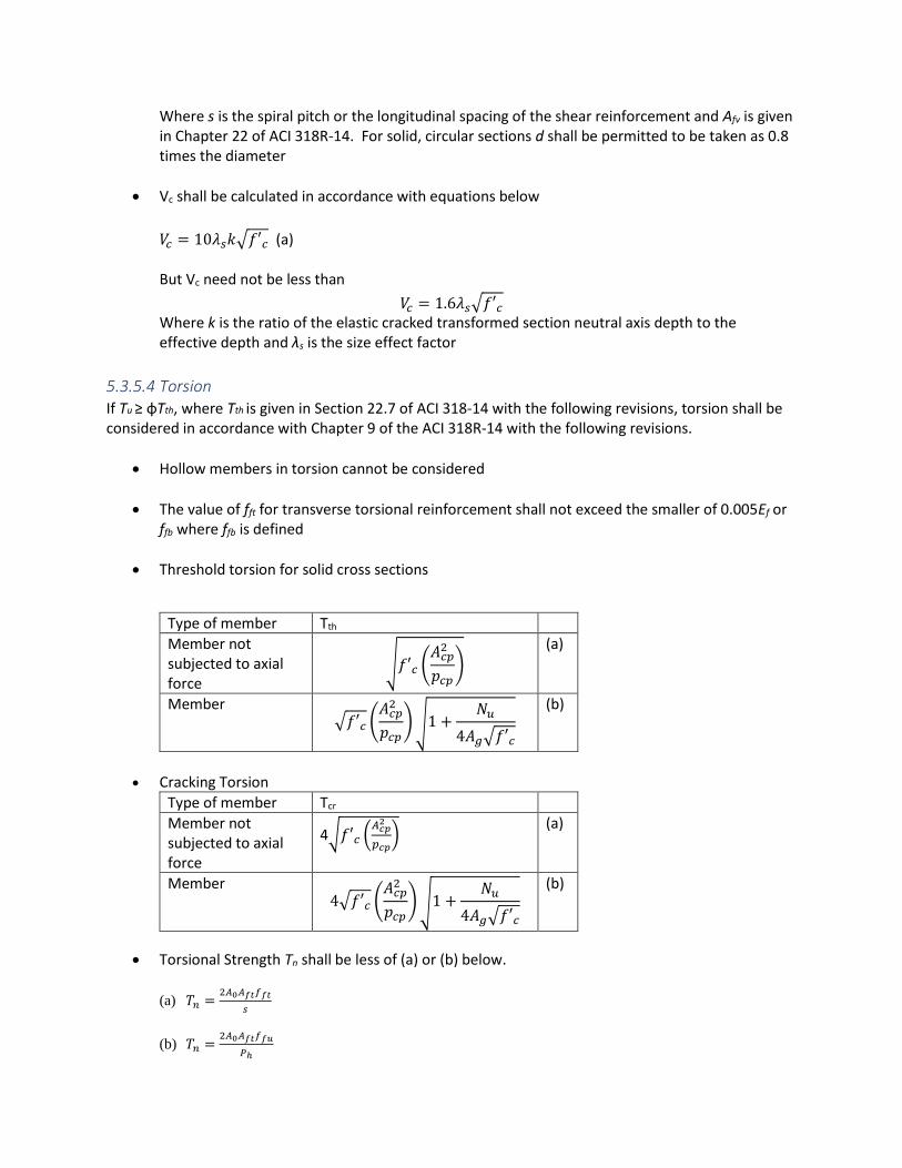
Where s is the spiral pitch or the longitudinal spacing of the shear reinforcement and Afv is given in Chapter 22 of ACI 318R-14. For solid, circular sections d shall be permitted to be taken as 0.8 times the diameter
• Vc shall be calculated in accordance with equations below
𝑉𝑐 = 10𝜆𝑠𝑘√𝑓′𝑐 (a)
But Vc need not be less than
𝑉𝑐 = 1.6𝜆𝑠√𝑓′𝑐 Where k is the ratio of the elastic cracked transformed section neutral axis depth to the effective depth and λs is the size effect factor
5.3.5.4 Torsion
If Tu ≥ φTth, where Tth is given in Section 22.7 of ACI 318-14 with the following revisions, torsion shall be considered in accordance with Chapter 9 of the ACI 318R-14 with the following revisions.
• Hollow members in torsion cannot be considered
• The value of fft for transverse torsional reinforcement shall not exceed the smaller of 0.005Ef or ffb where ffb is defined
• Threshold torsion for solid cross sections
Type of member Tth
Member not subjected to axial force
√𝑓′𝑐 (𝐴𝑐𝑝
2
𝑝𝑐𝑝)
(a)
Member √𝑓′𝑐 (
𝐴𝑐𝑝2
𝑝𝑐𝑝) √1 +
𝑁𝑢
4𝐴𝑔√𝑓′𝑐
(b)
• Cracking Torsion
Type of member Tcr
Member not subjected to axial force
4√𝑓′𝑐 (𝐴𝑐𝑝
2
𝑝𝑐𝑝)
(a)
Member 4√𝑓′𝑐 (
𝐴𝑐𝑝2
𝑝𝑐𝑝) √1 +
𝑁𝑢
4𝐴𝑔√𝑓′𝑐
(b)
• Torsional Strength Tn shall be less of (a) or (b) below.
(a) 𝑇𝑛 =2𝐴0𝐴𝑓𝑡𝑓𝑓𝑡
𝑠
(b) 𝑇𝑛 =2𝐴0𝐴𝑓𝑡𝑓𝑓𝑢
𝑃ℎ

• Cross-sectional dimension shall be selected such that for solid sections
√(𝑉𝑢
𝑏𝑤𝑑)
2
+ (𝑇𝑢𝑝ℎ
1.7𝐴𝑜ℎ2 )
2
≤ 𝜙 (0.2𝑓𝑐′)
5.3.6 Reinforcement limits
5.3.6.1 Minimum and maximum longitudinal reinforcement
Area of longitudinal reinforcement shall be at least 0.01Ag but shall not exceed 0.08Ag.
5.3.6.2 Minimum Shear Reinforcement
Minimum area of shear reinforcement, Afv,min shall be provided in all regions where Vu>0.5φVc
If shear reinforcement is required, Afv,min shall be the greater of (a) and (b):
(a) 0.75 ∗ √𝑓𝑐′𝑏𝑤𝑠
𝑓𝑓𝑣
(b) 50 ∗𝑏𝑤𝑠
𝑓𝑓𝑣
5.3.7 Reinforcement detailing
5.3.7.1 General
Concrete cover for reinforcement shall be in accordance with Chapter 20.6 of ACI 318R-14 and utilizing the table below.
Concrete Exposure Member Reinforcement Specified Cover, in
Cast against and permanently in contact with ground
All All 3
Exposed to weather All No. 5 bar and smaller 1.5
Not exposed to weather or cast against the ground
Slabs, joists, and walls
All ¾
Beams, columns, pedestals, and tension ties
All 1-1/2
5.3.7.3 Longitudinal reinforcement
The minimum number of longitudinal bars shall be (a), (b), or (c):
(a) Three within triangular ties (b) Four within rectangular or circular ties

(c) Six enclosed by spirals
5.3.8.4 Splices of Longitudinal Reinforcement
5.3.8.4.2 Lap Splices
If the bar force due to factored loads is compressive, compression lap splices shall be permitted. Compression splices shall be designed in accordance with 25.5 of ACI 318R-14 assuming ff = 0.25 ffu. It shall be permitted to decrease the compression lap splice length in accordance with (a) or (b), but the lap splice length shall be at least 12 in.
(a) For tied columns, where ties throughout the lap splice length have an effective area not less than 0.0065hs in both directions, lap splice length shall be permitted to be multiplied by 0.83. Tie legs perpendicular to dimension h shall be considered in calculating effective area.
(b) For spiral columns, where spirals throughout the lap splice length satisfy 25.7.3, lap splice length shall be permitted to be multiplied by 0.75.
If the bar force due to factored loads is tensile, tension lap splices shall be in accordance with table below.
Tension Lap Splice Class Table
5.3.8.5 Transverse reinforcement
5.3.8.5.1 General
• Transverse reinforcement shall satisfy the most restrictive requirements for reinforcement spacing and it shall be anchored at each end.
• Details of transverse reinforcement shall be in accordance with 25.7.2 for ties or 25.7.3 for spirals.
• Longitudinal reinforcement shall be laterally supported using ties in accordance with 5.2.8.5.2 or spirals in accordance with, unless tests and structural analyses demonstrate adequate strength and feasibility of construction.
• Diameter of GFRP tie bar shall be at least #3
• Rectilinear GFRP ties shall be arranged to satisfy (a), (b), and (c)

(a) Every corner and alternate longitudinal bar shall have lateral support provided by the corner of a tie with an included angle of not more than 135 degrees
(b) Each bar shall have less than 6 in. clear on each side along the tie from laterally supported bar
(c) Overlaps at end of adjacent rectilinear ties shall be staggered around the perimeter
• Anchorage of each GFRP stirrup leg shall be in accordance with (a) or (b)
(a) Standard hook around longitudinal reinforcement at both ends (b) Lap of at least 20db on one end and standard hook around longitudinal reinforcement on the
other end
5.3.8.5.2 Lateral Support of Longitudinal bars using ties
In any story, the bottom tie shall be located not more than one-half the tie or hoop spacing above the top of footing or slab.
In any story, the top tie shall be located not more than one-half the tie or hoop spacing below the lowest horizontal reinforcement in the slab, drop panel, or shear cap. If beams or brackets frame into all sides of the column, the top tie or hoop shall be located not more than 3 in. below the lowest horizontal reinforcement in the shallowest beam or bracket.
5.3.8.5.3 Lateral Support of Longitudinal bars using spirals In any story, the bottom of the spiral shall be located at the top of footing or slab. In any story, the top of the spiral shall be located in accordance with Table below
Table - Spiral extension requirements at top of column
Framing at column end Extension requirements
Beams or brackets frame into all sides of the column
Extend to the level of the lowest horizontal reinforcement in members supported above.
Beams or brackets do not frame into all sides of the column
Extend to the level of the lowest horizontal reinforcement in members supported above. Additional column ties shall extend above termination of spiral to bottom of slab, drop panel, or shear cap.
Columns with capitals Extend to the level at which the diameter or width of capital is twice that of the column.
5.3.8.5.4 Shear If required, shear reinforcement shall be provided using ties or spirals.
Maximum spacing of shear reinforcement shall be the lesser of d/4 or 12 in.
5.4 Walls
5.4.1 – Scope This chapter shall apply to the design of nonprestressed walls including the following
(a) Cast-in-place
(b) Precast in-plant

(c) Precast on-site including tilt-up
GFRP reinforcement in compression is permitted. When present, the area of GFRP reinforcement in
compression shall be treated as having the same strength and stiffness as the concrete in the
surrounding compression zone.
For straight bars, the design strength ffu shall be determine according to the equation below.
𝑓𝑓𝑢 = 𝐶𝐸𝑓𝑓𝑢
Where
ffu = guaranteed ultimate tensile strength
CE = environmental reduction factor, which shall b permitted to be taken as 0l.85 for concrete
both exposed and not exposed to earth or weather
5.4.2 – General Information
5.4.2.1 – Materials
Design properties for GFRP reinforcement shall be selected based on the material properties discussed earlier in this design manual.
5.4.2.2 – Connection to other members
• Contribution of GFRP reinforcement to the nominal shear strength Vn at the contact surface
between supported member and foundation shall be verified,
• For connections between a cast-in-place column or pedestal and foundation, Af crossing the
interface shall be at least 0.01Ag, where Ag is the gross area of the supported member
• Where moments are transferred to the foundation, reinforcement, or dowels shall satisfy ACI
318R-14. Lap splice lengths shall not be less than 60 db
5.4.2.3 – Load distribution
Unless otherwise demonstrated by an analysis, the horizontal length of wall considered as effective for
resisting each concentrated load shall not exceed the lesser of the center-to-center distance between
loads, and the bearing width plus four times the wall thickness. Effective horizontal length for bearing
shall not extend beyond vertical wall joints unless design provides for transfer of forces across the joints.
5.4.2.4 – Intersecting elements
Walls shall be anchored to intersecting elements, such as floors and roofs; columns, pilasters, buttresses, or intersecting walls; and to footings.
5.4.3 – Design Limits
5.4.3.1 Minimum wall thickness
Minimum wall thicknesses shall be in accordance with the Table below. Thinner walls are permitted if
adequate strength and stability can be demonstrated by structural analysis.
Wall Type Minimum Wall Thickness h
Bearing (1) Greater of 5.5 in (a)

1/24 the lesser of unsupported length and unsupported height
(b)
Nonbearing Greater of 4 in (c)
1/30 the lesser of unsupported length and unsupported height
(d)
Exterior basement and foundation
7.5 in (e)
(1) Only applies to walls designed in accordance with the simplified design method
5.4.4 – Required Strength
5.4.4.1 General
Required strength shall be calculated in accordance with the factored load combinations
Required strength shall be calculated in accordance with the analysis procedures
Slenderness effects shall be calculated
Walls shall be designed for eccentric axial loads and any lateral or other loads to which they are
subjected.
5.4.4.2 Factored axial force and moment
Walls shall be designed for the maximum factored moment Mu that can accompany the factored axial
force for each applicable load combination. The factored axial force Pu at given eccentricity shall not
exceed φPn,max, where Pn,max shall be as given in maximum axial strength table below and strength
reduction factor φ shall be that for compression-controlled sections in the strength reduction factor
table below. The maximum factored moment Mu shall be magnified for slenderness effects in
accordance with 6.6.4 of ACI 318R-14 with the exception of columns or 6.7 of ACI 318R-14.
Maximum axial strength
Transverse Reinforcement
Pn,max
Ties 0.80 Po (a)
Spirals 0.85 Po (b)
Strength reduction factor φ for moment, axial force, or combined moment and axial force
Net tensile strain at failure in the outermost layer of reinforcement, εft
Classification φ
𝜀𝑓𝑡 = 𝜀𝑓𝑢 Tension-controlled 0.55
𝜀𝑓𝑢 > 𝜀𝑓𝑡 > 0.8𝜀𝑓𝑢 Transition 1.05 − 0.5 𝜀𝑓𝑡 𝜀𝑓𝑢⁄
𝜀𝑓𝑡 ≤ 0.8𝜀𝑓𝑢 Compression-controlled 0.65
5.4.4.3 Factored shear
Walls shall be designed for the maximum in-plan Vu and out-of-plane Vu
5.4.5 – Design Strength
5.4.5.1 General
For each applicable factored load combination, design strength at all sections shall satisfy φSn ≥ U, including (a) through (c). Interaction between axial load and moment shall be considered.
(a) φPn ≥ Pu (b) φMn ≥ Mu (c) φVn ≥ Vu
φ shall be determined in accordance with 21.2.
5.4.5.2 Axial load and in-plane or out-of-plane flexure
For bearing walls, Pn and Mn (in-plane or out-of-plane) shall be calculated in accordance with 22.4 of ACI 318R-14 with the additions below. Alternatively, axial load and out-of-plane flexure shall be permitted to be considered in accordance with 11.5.3.
• For members reinforced with GFRP, Po shall be calculated with equation below 𝑃𝑜 = 0.85𝑓𝑐
′𝐴𝑔
• Nominal axial tensile strength of concrete members reinforced with GFRP, Pnt shall not be taken greater than Pnt,max calculated by equation below
𝑃𝑛𝑡,𝑚𝑎𝑥 = 𝑓𝑓𝑢𝐴𝑓
For nonbearing walls, Mn shall be calculated in accordance with 22.3 of ACI 318R-14.
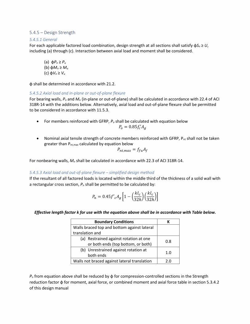
5.4.5.3 Axial load and out-of-plane flexure – simplified design method
If the resultant of all factored loads is located within the middle third of the thickness of a solid wall with
a rectangular cross section, Pn shall be permitted to be calculated by:
𝑃𝑛 = 0.45𝑓′𝑐𝐴𝑔 [1 − (𝑘𝑙𝑐
32ℎ) (
𝑘𝑙𝑐
32ℎ)]
Effective length factor k for use with the equation above shall be in accordance with Table below.
Boundary Conditions K
Walls braced top and bottom against lateral translation and
(a) Restrained against rotation at one or both ends (top bottom, or both)
0.8
(b) Unrestrained against rotation at both ends
1.0
Walls not braced against lateral translation 2.0
Pn from equation above shall be reduced by φ for compression-controlled sections in the Strength
reduction factor φ for moment, axial force, or combined moment and axial force table in section 5.3.4.2
of this design manual
Wall reinforcement shall be at least that required by 11.6 of ACI 318R-14
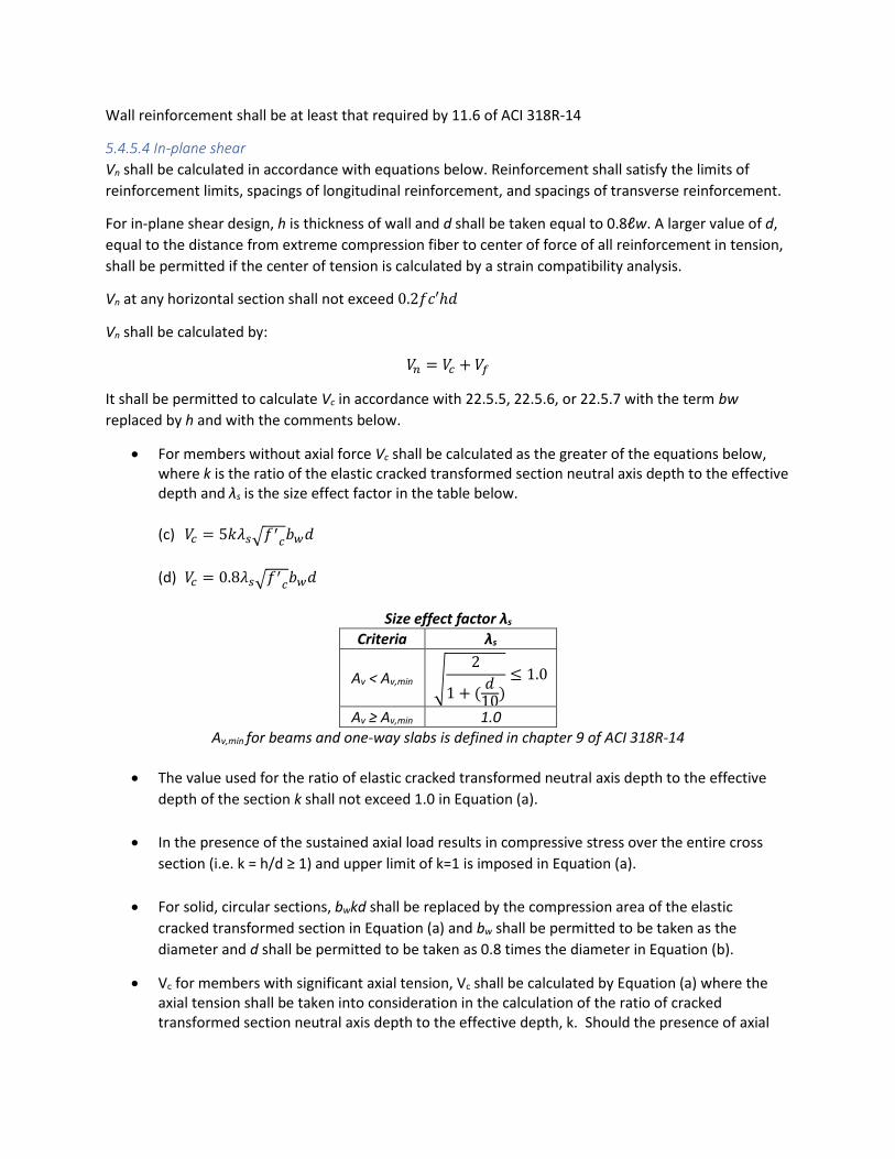
5.4.5.4 In-plane shear
Vn shall be calculated in accordance with equations below. Reinforcement shall satisfy the limits of
reinforcement limits, spacings of longitudinal reinforcement, and spacings of transverse reinforcement.
For in-plane shear design, h is thickness of wall and d shall be taken equal to 0.8ℓw. A larger value of d,
equal to the distance from extreme compression fiber to center of force of all reinforcement in tension,
shall be permitted if the center of tension is calculated by a strain compatibility analysis.
Vn at any horizontal section shall not exceed 0.2𝑓𝑐′ℎ𝑑
Vn shall be calculated by:
𝑉𝑛 = 𝑉𝑐 + 𝑉𝑓
It shall be permitted to calculate Vc in accordance with 22.5.5, 22.5.6, or 22.5.7 with the term bw
replaced by h and with the comments below.
• For members without axial force Vc shall be calculated as the greater of the equations below, where k is the ratio of the elastic cracked transformed section neutral axis depth to the effective depth and λs is the size effect factor in the table below.
(c) 𝑉𝑐 = 5𝑘𝜆𝑠√𝑓′𝑐𝑏𝑤𝑑
(d) 𝑉𝑐 = 0.8𝜆𝑠√𝑓′𝑐𝑏𝑤𝑑
Size effect factor λs
Criteria λs
Av < Av,min √2
1 + (𝑑
10)≤ 1.0
Av ≥ Av,min 1.0
Av,min for beams and one-way slabs is defined in chapter 9 of ACI 318R-14
• The value used for the ratio of elastic cracked transformed neutral axis depth to the effective
depth of the section k shall not exceed 1.0 in Equation (a).
• In the presence of the sustained axial load results in compressive stress over the entire cross
section (i.e. k = h/d ≥ 1) and upper limit of k=1 is imposed in Equation (a).
• For solid, circular sections, bwkd shall be replaced by the compression area of the elastic
cracked transformed section in Equation (a) and bw shall be permitted to be taken as the
diameter and d shall be permitted to be taken as 0.8 times the diameter in Equation (b).
• Vc for members with significant axial tension, Vc shall be calculated by Equation (a) where the axial tension shall be taken into consideration in the calculation of the ratio of cracked transformed section neutral axis depth to the effective depth, k. Should the presence of axial
load result in tensile stress over the entire cross section, shear reinforcement shall be designed to resist total shear.
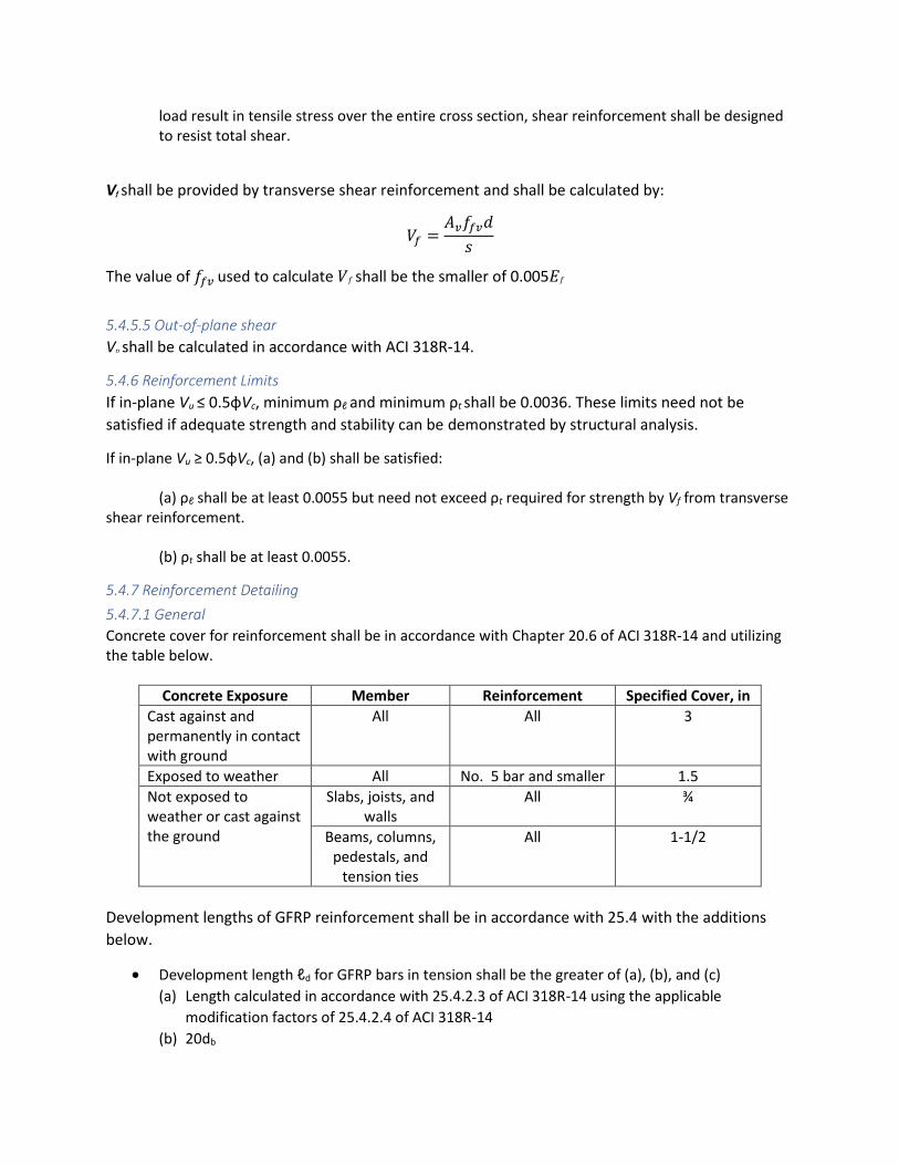
Vf shall be provided by transverse shear reinforcement and shall be calculated by:
𝑉𝑓 =𝐴𝑣𝑓𝑓𝑣𝑑
𝑠
The value of 𝑓𝑓𝑣 used to calculate 𝑉𝑓 shall be the smaller of 0.005𝐸𝑓
5.4.5.5 Out-of-plane shear
Vn shall be calculated in accordance with ACI 318R-14.
5.4.6 Reinforcement Limits
If in-plane Vu ≤ 0.5φVc, minimum ρℓ and minimum ρt shall be 0.0036. These limits need not be
satisfied if adequate strength and stability can be demonstrated by structural analysis.
If in-plane Vu ≥ 0.5φVc, (a) and (b) shall be satisfied:
(a) ρℓ shall be at least 0.0055 but need not exceed ρt required for strength by Vf from transverse shear reinforcement.
(b) ρt shall be at least 0.0055.
5.4.7 Reinforcement Detailing
5.4.7.1 General
Concrete cover for reinforcement shall be in accordance with Chapter 20.6 of ACI 318R-14 and utilizing the table below.
Concrete Exposure Member Reinforcement Specified Cover, in
Cast against and permanently in contact with ground
All All 3
Exposed to weather All No. 5 bar and smaller 1.5
Not exposed to weather or cast against the ground
Slabs, joists, and walls
All ¾
Beams, columns, pedestals, and
tension ties
All 1-1/2
Development lengths of GFRP reinforcement shall be in accordance with 25.4 with the additions
below.
• Development length ℓd for GFRP bars in tension shall be the greater of (a), (b), and (c)
(a) Length calculated in accordance with 25.4.2.3 of ACI 318R-14 using the applicable
modification factors of 25.4.2.4 of ACI 318R-14
(b) 20db

(c) 12 in
• For GFRP bars ℓd shall be calculated by equation below.
𝑙𝑑 =
𝑑𝑏 (𝑓𝑓𝑟
√𝑓𝑐′
− 340) 𝜓𝑡
13.6 +𝑐𝑏
𝑑𝑏
which the term 𝑐𝑏 𝑑𝑏⁄ shall not be taken greater than 3.5, ffr is the stress in the GFRP bar
required to develop the full nominal sectional capacity
• Any mechanical attachment or device capable of developing 1.25*ffu of GFRP bars shall be
permitted, provided it is approved by the building official in accordance with 1.10. Development
of GFRP bars in tension shall be permitted to consist of a combination of mechanical anchorage
plus additional embedment length of the GFRP bars between the critical section and the
mechanical attachment or device.
Splice lengths of GFRP reinforcement shall be in accordance with 25.5 with the comments below.
• Tension lap splice length ℓst for GFRPbars in tension shall be in accordance with table below.
As,provided/As,require d [1] over length of
splice
Maximum percent of As spliced within required lap length
Splice Type ℓst
≥ 2.0 50 Class A Greater of 1.0ℓd, 20db, and
12 in
100 Class B Greater of
1.3ℓd, 20db, and 12 in and 12 in. <2.0 All cases Class B
• A mechanical splice shall develop in tension or compression, as required, at least 1.25ffu of the
bar.
• Mechanical splices shall not contain any parts that are susceptible to corrosion.
5.4.7.2 Spacing of Longitudinal Reinforcement
Spacing s of longitudinal bars in cast-in-place walls shall not exceed the lesser of 3h and 12 in. If shear
reinforcement is required for in-plane strength, spacing of longitudinal reinforcement shall not exceed
ℓw/3.
For walls with h greater than 10 in., except basement walls and cantilever retaining walls, distributed reinforcement for each direction shall be placed in two layers parallel with wall faces in accordance with (a) and (b):
(a) One layer consisting of at least one-half and not exceeding two-thirds of total reinforcement required for each direction shall be placed at least 2 in., but not exceeding h/3, from the exterior surface.
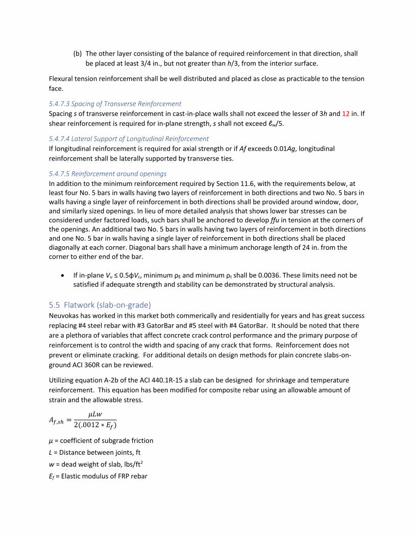
(b) The other layer consisting of the balance of required reinforcement in that direction, shall
be placed at least 3/4 in., but not greater than h/3, from the interior surface.
Flexural tension reinforcement shall be well distributed and placed as close as practicable to the tension
face.
5.4.7.3 Spacing of Transverse Reinforcement
Spacing s of transverse reinforcement in cast-in-place walls shall not exceed the lesser of 3h and 12 in. If
shear reinforcement is required for in-plane strength, s shall not exceed ℓw/5.
5.4.7.4 Lateral Support of Longitudinal Reinforcement
If longitudinal reinforcement is required for axial strength or if Af exceeds 0.01Ag, longitudinal
reinforcement shall be laterally supported by transverse ties.
5.4.7.5 Reinforcement around openings
In addition to the minimum reinforcement required by Section 11.6, with the requirements below, at least four No. 5 bars in walls having two layers of reinforcement in both directions and two No. 5 bars in walls having a single layer of reinforcement in both directions shall be provided around window, door, and similarly sized openings. In lieu of more detailed analysis that shows lower bar stresses can be considered under factored loads, such bars shall be anchored to develop ffu in tension at the corners of the openings. An additional two No. 5 bars in walls having two layers of reinforcement in both directions and one No. 5 bar in walls having a single layer of reinforcement in both directions shall be placed diagonally at each corner. Diagonal bars shall have a minimum anchorage length of 24 in. from the corner to either end of the bar.
• If in-plane Vu ≤ 0.5φVc, minimum ρℓ and minimum ρt shall be 0.0036. These limits need not be satisfied if adequate strength and stability can be demonstrated by structural analysis.
5.5 Flatwork (slab-on-grade) Neuvokas has worked in this market both commerically and residentially for years and has great success
replacing #4 steel rebar with #3 GatorBar and #5 steel with #4 GatorBar. It should be noted that there
are a plethora of variables that affect concrete crack control performance and the primary purpose of
reinforcement is to control the width and spacing of any crack that forms. Reinforcement does not
prevent or eliminate cracking. For additional details on design methods for plain concrete slabs-on-
ground ACI 360R can be reviewed.
Utilizing equation A-2b of the ACI 440.1R-15 a slab can be designed for shrinkage and temperature
reinforcement. This equation has been modified for composite rebar using an allowable amount of
strain and the allowable stress.
𝐴𝑓,𝑠ℎ =𝜇𝐿𝑤
2(.0012 ∗ 𝐸𝑓)
μ = coefficient of subgrade friction
L = Distance between joints, ft
w = dead weight of slab, lbs/ft2
Ef = Elastic modulus of FRP rebar

Af,sh = cross-sectional area of FRP reinforcement
Using this calculation with an elastic modulus of 6,810,000 psi, dead weight of 145 lbs/ft^3, a 1.5
coefficient of friction, and a distance between control joints of 10 feet a rebar spacing for various
concrete thickness can be calculated.
• 4” concrete– 29.9” ocew, 53” ocew #4 Shouldn’t this be calculated for #3?
• 6” concrete – 19.9” ocew, 35” ocew #4
• 8” concrete – 15” ocew #3, 26.5” ocew #4
This calculation ensures a sufficient reinforcement to ensure performance of the slab, and to actually
calculate the crack width various calculators have been developed to estimate the actual crack width
that will form. This calculation is complicated and best determined using these calculators. Once such
calculator is the CRCP 10 tool that was developed by the Center for Transportation Research in Austin.
Using this tool typically the rebar spacing can be increased by 30% without exceed the recommended
crack width recommended by AASHTO for concrete pavements. Based on this in addition to Neuvokas
field experience Neuvokas recommends the followings spacing using GatorBar.
• 4” concrete – 24” to 30” #3 GatorBar
• 6” concrete – 18” to 24” #3 GatorBar or 24” to 30” with #4 GatorBar
• 8” concrete – 12” to 18” #3 GatorBar or 18 to 24” with #4 GatorBar
It should be noted that, as is often the case with prescriptive applications, site conditions, load
considerations and other items can lead to changing these values for concrete spacing. These values are
intended to be starting place for further consideration.
5.6 Footers In the case of specific design, the engineer of record should be consulted, but in the case of prescriptive
footings for light-frame construction (as designated by the IBC) #3 GatorBar can be used replace #4 steel
and #4 GatorBar can be used to replace #5 steel.
Little engineering data is available on the current design requirements driving steel requirements and
the high strength of GatorBar allows the direct replacement.