Embed Size (px)
Citation preview

2006 Ogura Industrial Corporation
English
Español

2006 Ogura Industrial Corporation
PTO Clutch/BrakeInstallation and Maintenance
Ogura Industrial Corporation2006
Ogura Design
Ogura Industrial Corporation2006
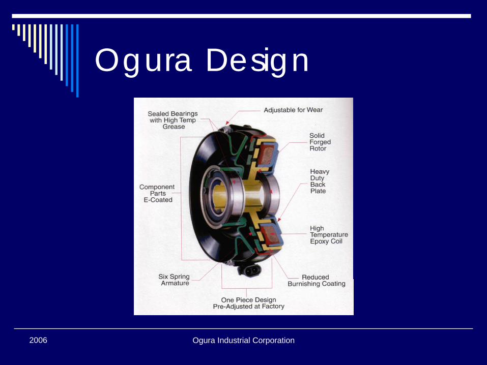
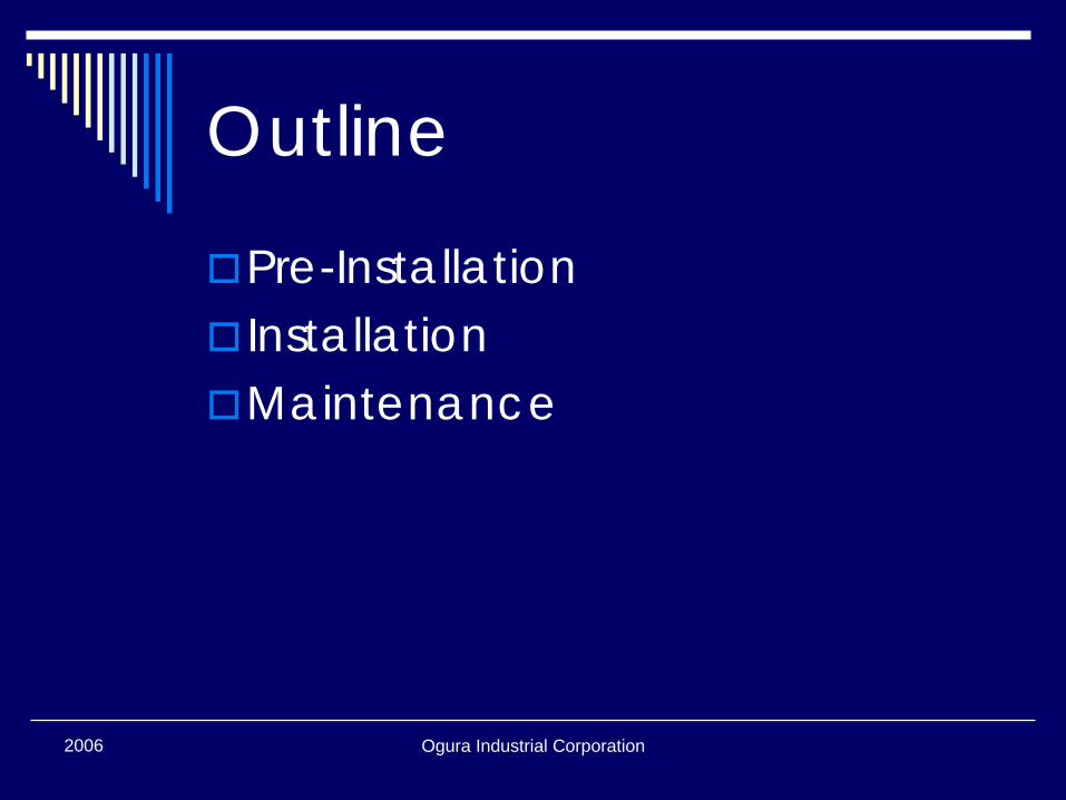
Outline
Pre-InstallationInstallationMaintenance
2006 Ogura Industrial Corporation
Pre-Installation
Ogura Industrial Corporation2006
Pre-Installation Check
Engine ShaftKey Length and HeightDirection of RotationBacking Plate Restraint
Ogura Industrial Corporation2006
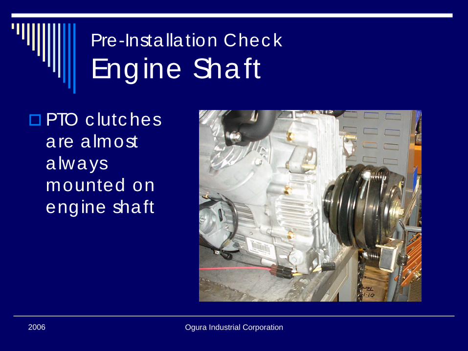
Pre-Installation Check
Engine ShaftPTO clutches are almost always mounted on engine shaft
Ogura Industrial Corporation2006
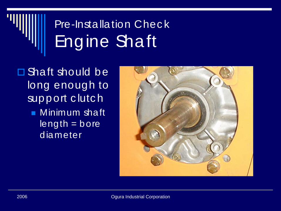
Pre-Installation Check
Engine ShaftShaft should be long enough to support clutch
Minimum shaft length = bore diameter
Ogura Industrial Corporation2006
Pre-Installation Check
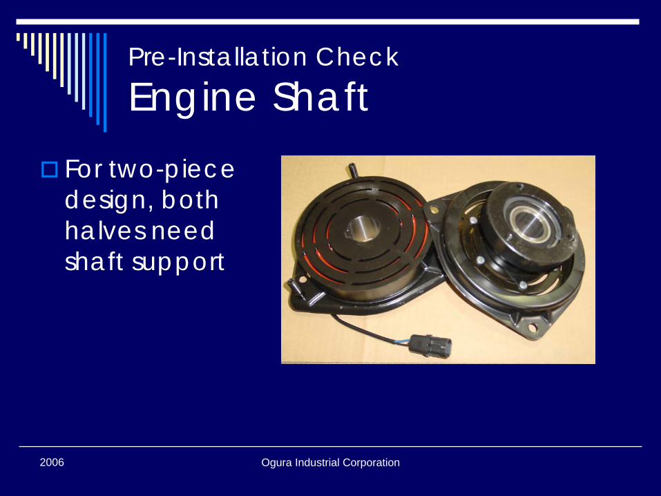
Engine ShaftFor two-piece design, both halves need shaft support
Ogura Industrial Corporation2006
Pre-Installation Check
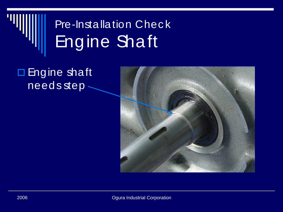
Engine ShaftEngine shaft needs step
Ogura Industrial Corporation2006
Pre-Installation Check
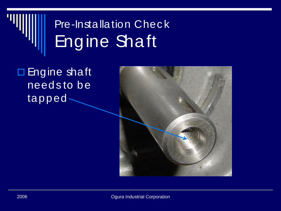
Engine ShaftEngine shaft needs to be tapped
Ogura Industrial Corporation2006
Pre-Installation Check
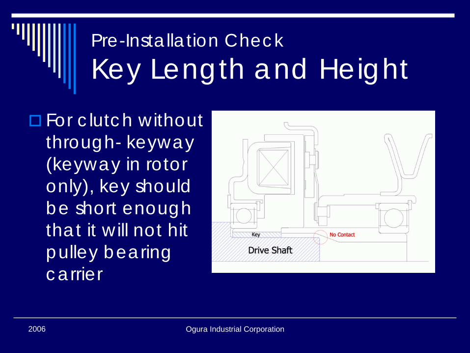
Key Length and HeightFor clutch without through- keyway(keyway in rotor only), key should be short enough that it will not hit pulley bearing carrier
Ogura Industrial Corporation2006
Pre-Installation Check
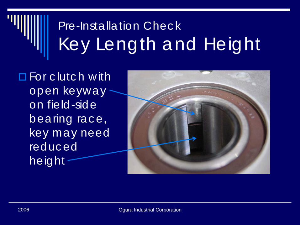
Key Length and HeightFor clutch with open keyway on field-side bearing race, key may need reduced height
Ogura Industrial Corporation2006
Pre-Installation Check
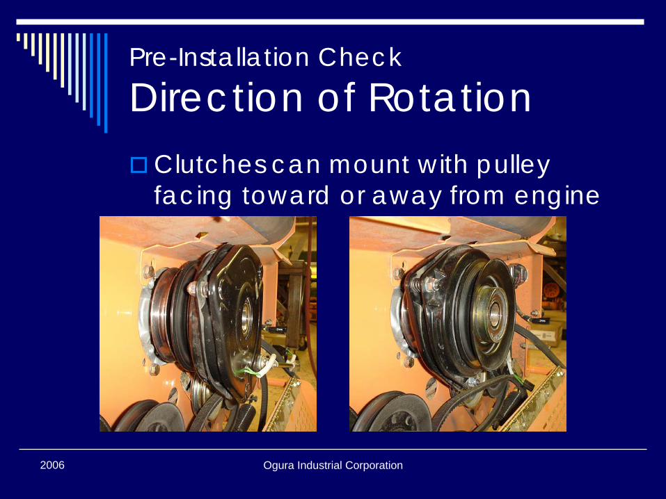
Direction of RotationClutches can mount with pulley facing toward or away from engine
Ogura Industrial Corporation2006
Pre-Installation Check
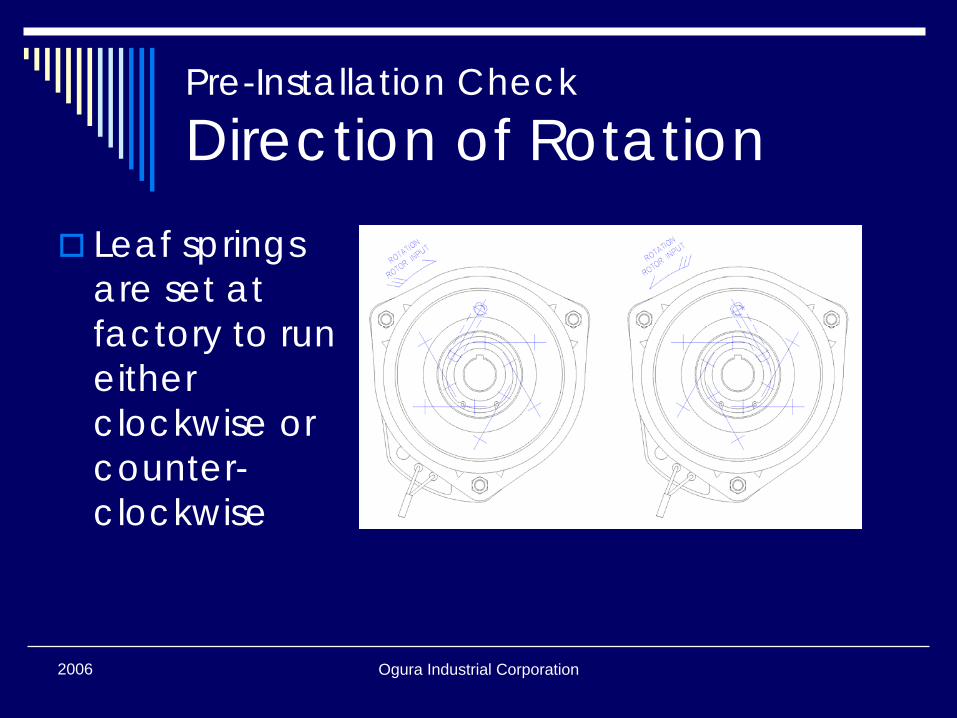
Direction of RotationLeaf springs are set at factory to run either clockwise or counter-clockwise
Ogura Industrial Corporation2006
Pre-Installation Check
Direction of RotationCheck direction of rotation to verify that spring direction is correctSprings should operate in tension and not compression(most engines rotate counterclockwise)
Ogura Industrial Corporation2006
Pre-Installation Check
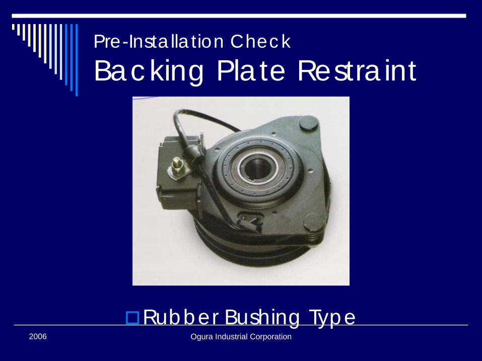
Backing Plate RestraintPTO backing plate only needs to withstand brake force
This can be 2 ~ 10 ft-lbs depending on clutch size
Ogura Industrial Corporation2006
Pre-Installation Check
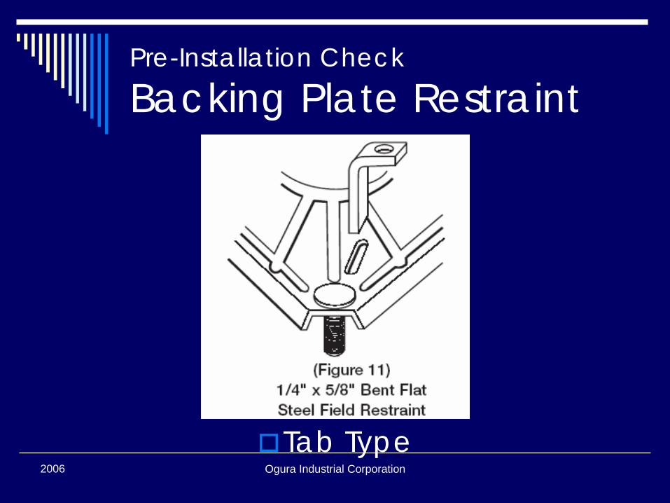
Backing Plate Restraint
Tab Type
Ogura Industrial Corporation2006
Pre-Installation Check
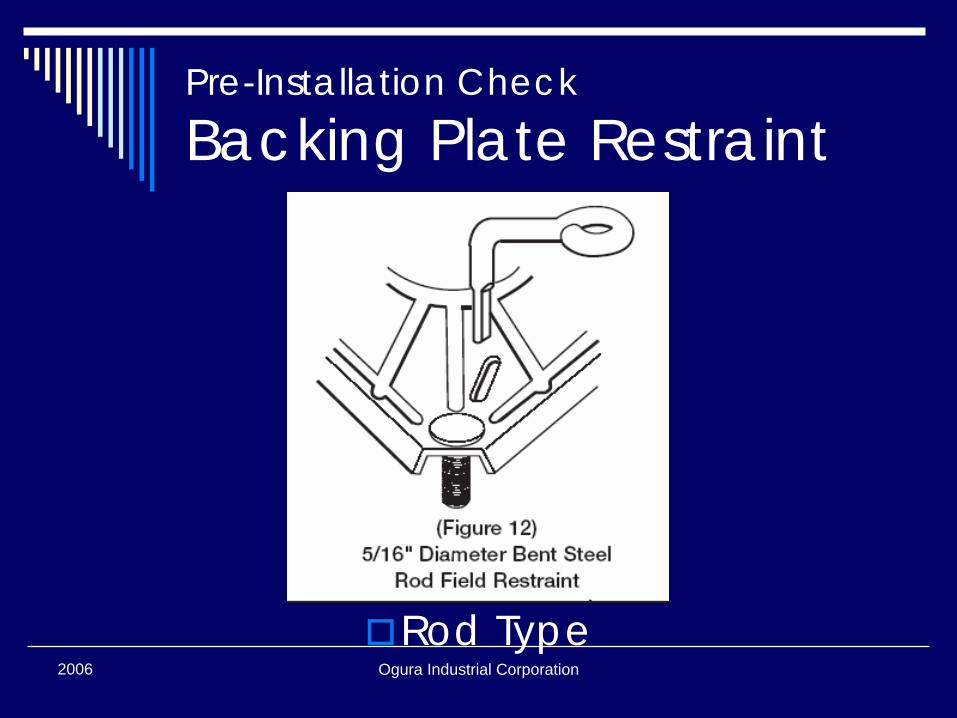
Backing Plate Restraint
Rod Type
Ogura Industrial Corporation2006
Pre-Installation Check
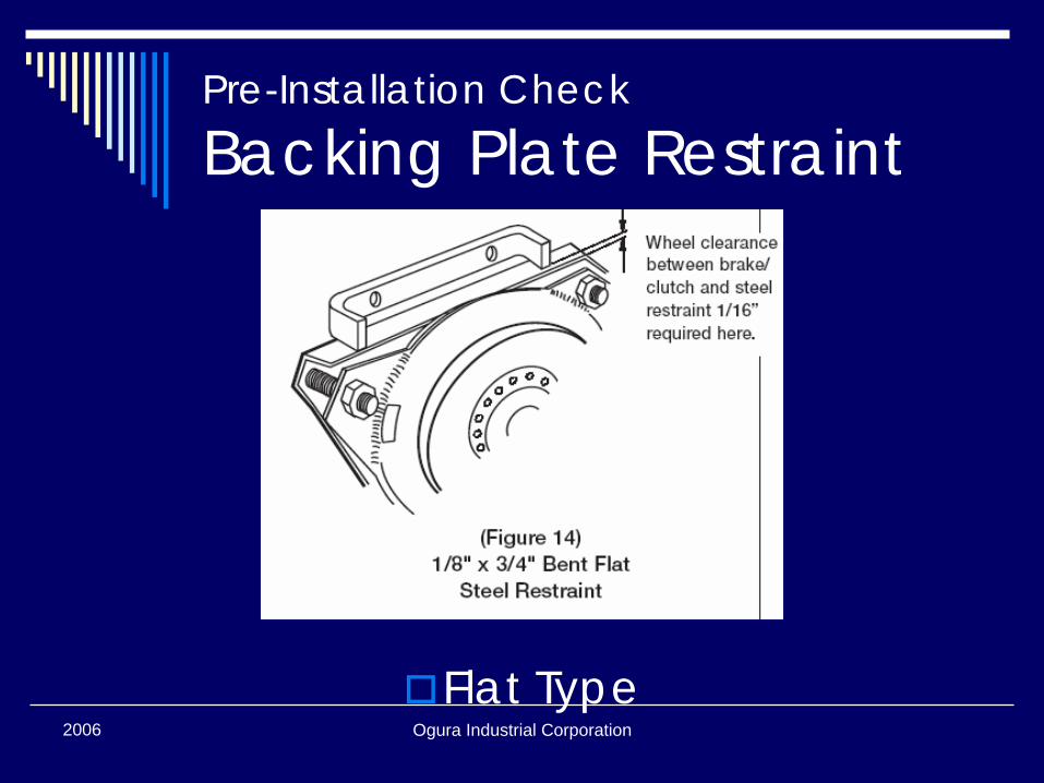
Backing Plate Restraint
Flat Type
Ogura Industrial Corporation2006
Pre-Installation Check
Backing Plate Restraint
Rubber Bushing Type

2006 Ogura Industrial Corporation
Installation
Ogura Industrial Corporation2006
PTO Clutch Installation① Verify appropriate shaft/pulley for clutch② Set key in shaft keyway if required
(some clutches have internal key)③ Slide clutch onto shaft④ Verify good contact with face of bearing
inner ring⑤ Tighten center bolt and washer⑥ Verify backing plate has slight axial and
radial freedom⑦ Connect power⑧ Burnish clutch
Ogura Industrial Corporation2006
PTO Clutch Installation #1
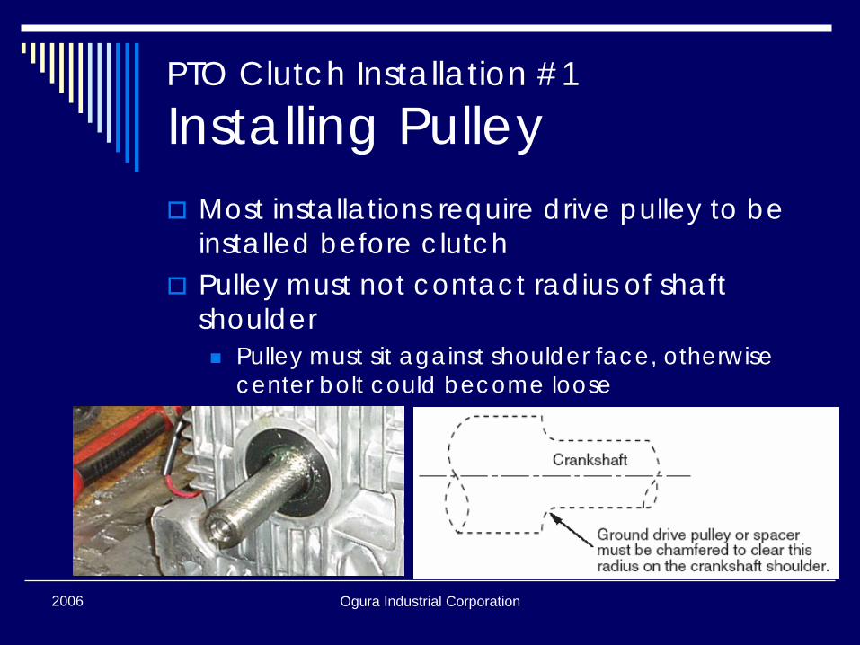
Installing PulleyMost installations require drive pulley to be installed before clutchPulley must not contact radius of shaft shoulder
Pulley must sit against shoulder face, otherwise center bolt could become loose
Ogura Industrial Corporation2006
PTO Clutch Installation #2
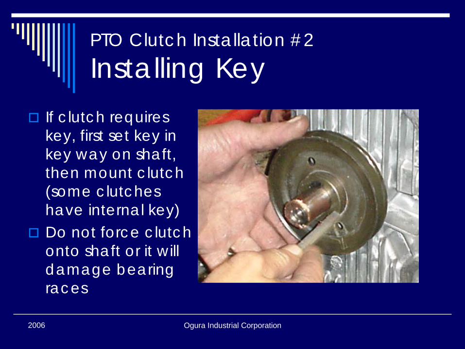
Installing KeyIf clutch requires key, first set key in key way on shaft, then mount clutch(some clutches have internal key)Do not force clutch onto shaft or it will damage bearing races
Ogura Industrial Corporation2006
PTO Clutch Installation #4
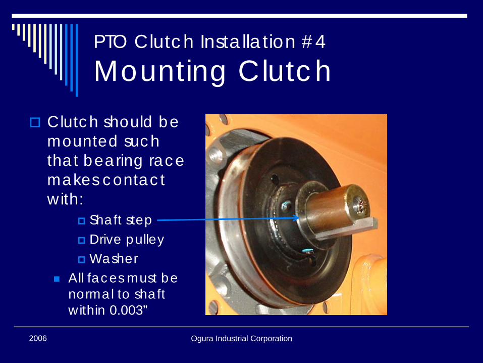
Mounting ClutchClutch should be mounted such that bearing race makes contact with:
Shaft stepDrive pulleyWasher
All faces must be normal to shaft within 0.003”
Ogura Industrial Corporation2006
PTO Clutch Installation #5
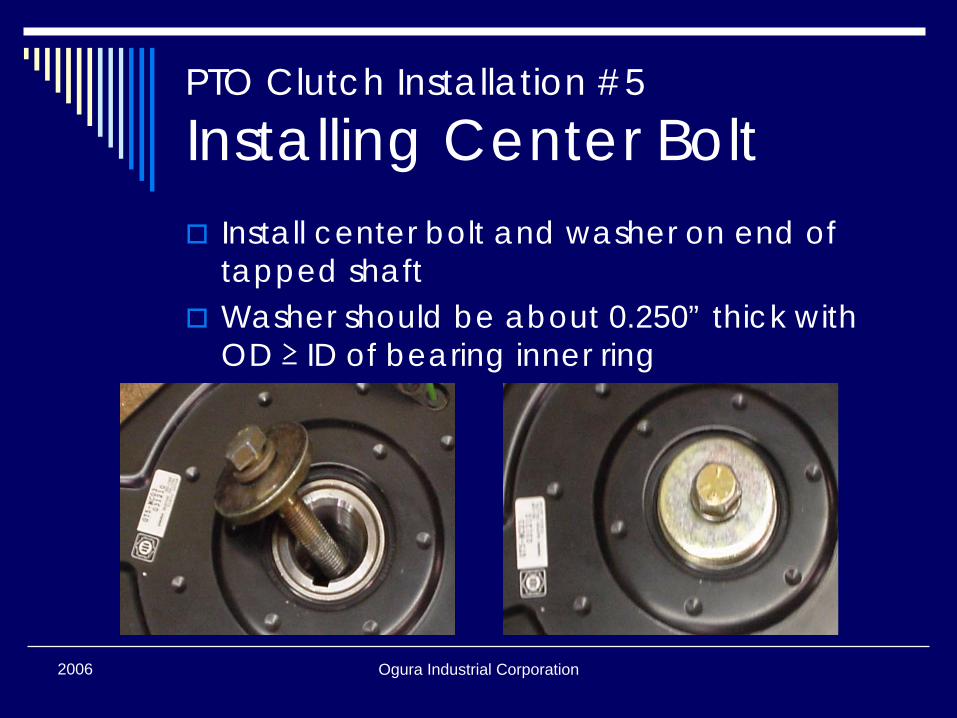
Installing Center BoltInstall center bolt and washer on end of tapped shaftWasher should be about 0.250” thick with OD ≥ ID of bearing inner ring
Ogura Industrial Corporation2006
PTO Clutch Installation #5
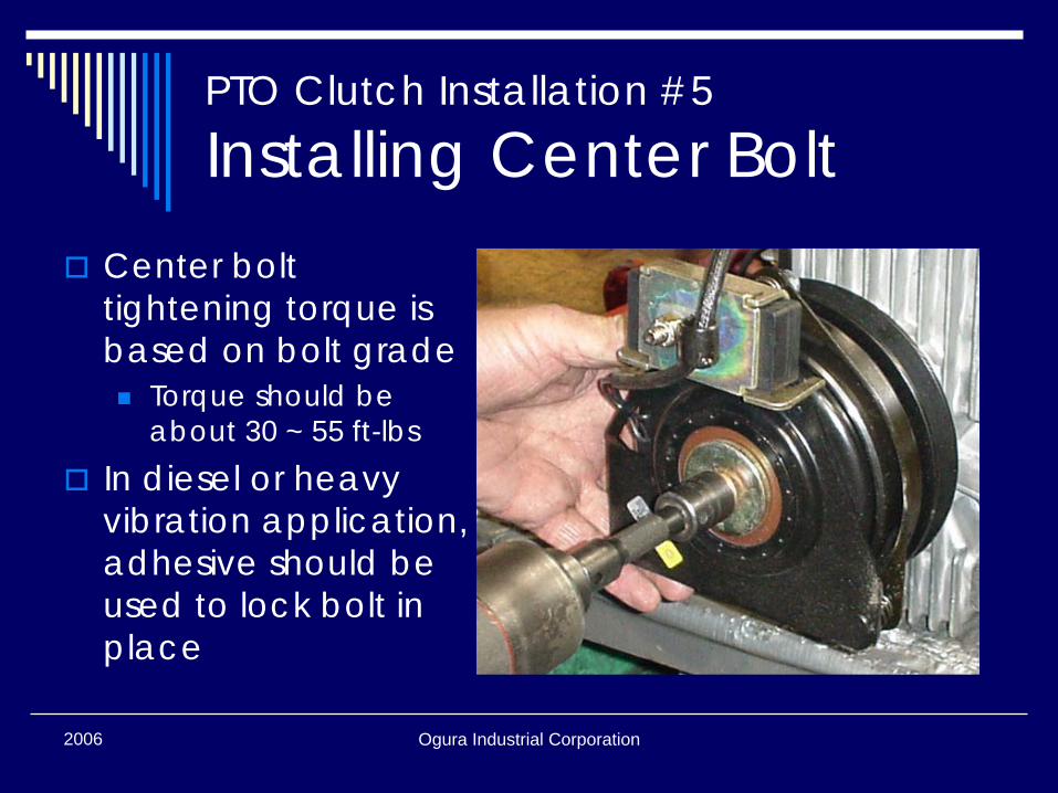
Installing Center BoltCenter bolt tightening torque is based on bolt grade
Torque should be about 30 ~ 55 ft-lbs
In diesel or heavy vibration application, adhesive should be used to lock bolt in place
Ogura Industrial Corporation2006
PTO Clutch Installation #6
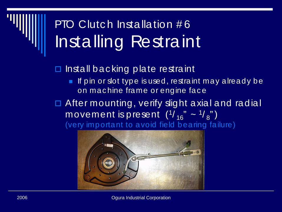
Installing RestraintInstall backing plate restraint
If pin or slot type is used, restraint may already be on machine frame or engine face
After mounting, verify slight axial and radial movement is present (1/16” ~ 1/8”)(very important to avoid field bearing failure)

Ogura Industrial Corporation2006
PTO Clutch Installation #7
Connecting PowerAttach terminal housing on clutch lead wire to corresponding power terminalTurn on electrical power on mower without starting engine if possibleTurn on PTO switch to verify clutch pulls in
Clutch will make “click” sound at engagement
Ogura Industrial Corporation2006
PTO Clutch Installation #8
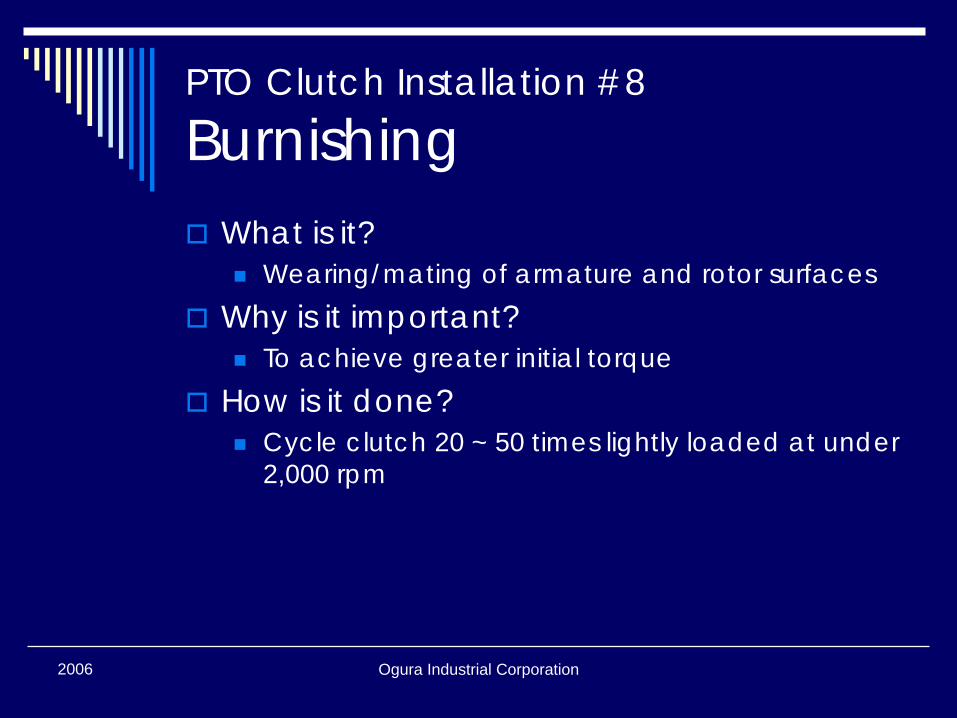
BurnishingWhat is it?
Wearing/mating of armature and rotor surfacesWhy is it important?
To achieve greater initial torqueHow is it done?
Cycle clutch 20 ~ 50 times lightly loaded at under 2,000 rpm
Ogura Industrial Corporation2006
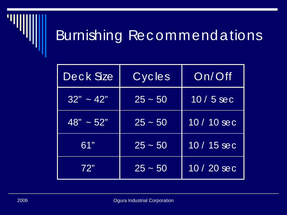
Burnishing Recommendations
Deck Size Cycles On/Off
32” ~ 42” 25 ~ 50 10 / 5 sec
48” ~ 52” 25 ~ 50 10 / 10 sec
61” 25 ~ 50 10 / 15 sec
72” 25 ~ 50 10 / 20 sec
2006 Ogura Industrial Corporation
Maintenance
Ogura Industrial Corporation2006
Maintenance
Most clutch parts do not require maintenance and can not be replaced
Bearings are sealed for life of clutchArmature, rotor, and brake wear evenly and can not be replaced individuallyCoil can not be removed
Ogura Industrial Corporation2006
Adjustment for Wear
All Ogura one-piece clutches are adjusted at factory(no initial adjustment required)As adjustable clutches wear, they can be re-gapped to extend overall life
Ogura Industrial Corporation2006
Adjustment for Wear
If clutch fails to pull in or will not continue to pull in when hot, air gap may need adjustmentTo make adjustments, taking PTO off mower may be easierNecessary equipment
0.015”~0.022” feeler gauge9/16” open-end box wrench
Ogura Industrial Corporation2006
Adjustment for Wear
Identify clutch model from label located on back of fieldThere are three inspection slots on brake shroudPlace feeler gauge in slot between armature and rotorSlowly tighten brake nut until armature and rotor contact feeler gauge
Ogura Industrial Corporation2006
Adjustment for Wear
Almost all Ogura clutches use 24UNF brake bolt, thus one turn of brake nut equates to approximately 0.04” of axial movement(for reference only: feeler gauge is still required)

Ogura Industrial Corporation2006
Adjustment for Wear
Ogura Industrial Corporation2006
Adjustment for Wear
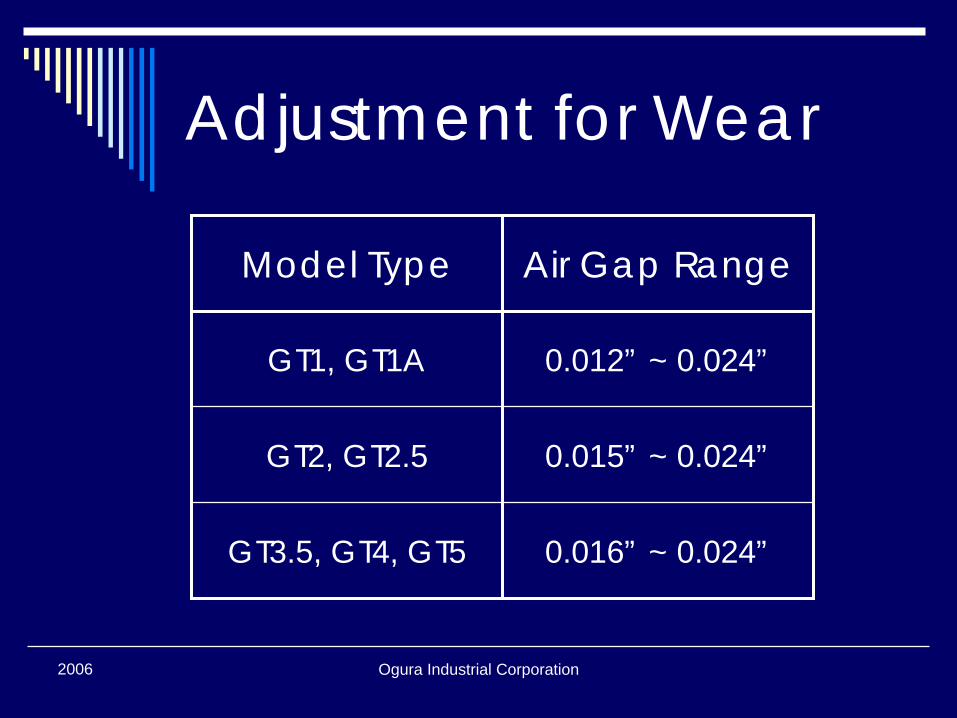
Model Type Air Gap Range
GT1, GT1A 0.012” ~ 0.024”
GT2, GT2.5 0.015” ~ 0.024”
GT3.5, GT4, GT5 0.016” ~ 0.024”
Ogura Industrial Corporation2006
Adjustment for Wear
Setting gap towards low range will increase cycle life between adjustmentsCaution: do not set gap below minimum or clutch may be damagedOnce gap is set, rotate armature and rotor, check gap with feeler gauge, and make adjustments as required
Ogura Industrial Corporation2006
Adjustment for Wear
Apply full voltage to clutchRotate armature and rotor to verify no contact between armature and brake shroudIf there is contact, back off brake nuts and retry until there is no contact

2006 Ogura Industrial Corporation
Thank YouEVERYTHING ABOUT AN OGURA CLUTCH WORKS
For more information on Ogura clutches, visit us on the web atwww.ogura-clutch.com

2006 Ogura Industrial Corporation
Embrague/Frenode PTOInstalación yMantenimiento
Ogura Industrial Corporation2006
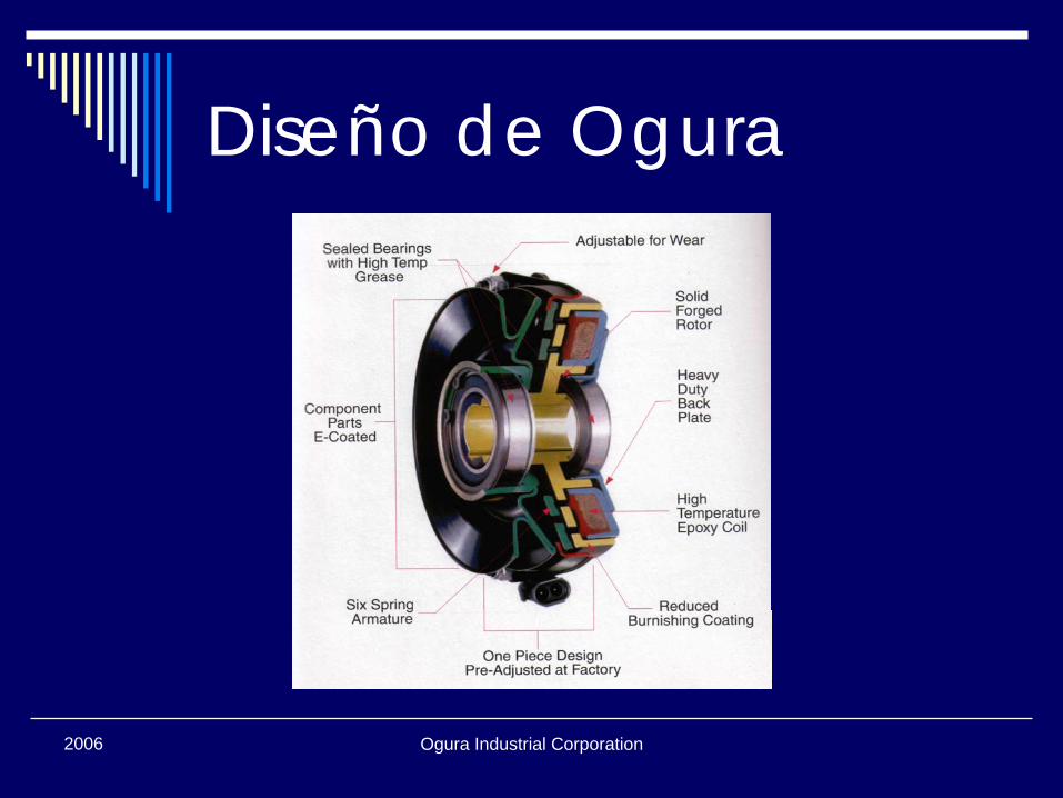
Diseño de Ogura
Ogura Industrial Corporation2006
Instrucciones
Instalación PreviaInstalaciónMantenimiento

2006 Ogura Industrial Corporation
InstalaciónPrevia
Ogura Industrial Corporation2006
Chequeo deInstalación Previa
Eje de MotorLongitud y Altura DominantesDirección de RotaciónPlaca Tracera de Contenimiento
Ogura Industrial Corporation2006
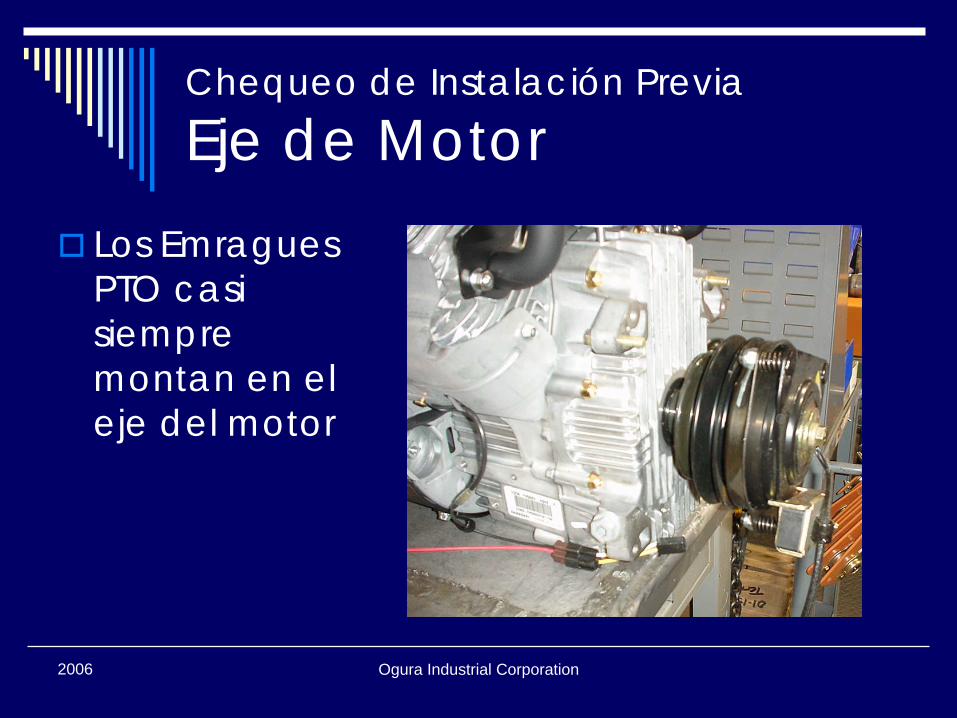
Chequeo de Instalación Previa
Eje de MotorLos EmraguesPTO casi siempre montan en el eje del motor
Ogura Industrial Corporation2006
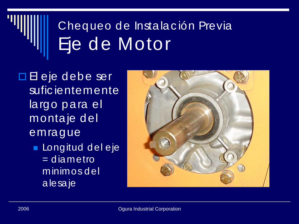
Chequeo de Instalación Previa
Eje de MotorEl eje debe ser suficientemente largo para el montaje del emrague
Longitud del eje = diametrominimos del alesaje
Ogura Industrial Corporation2006
Chequeo de Instalación Previa
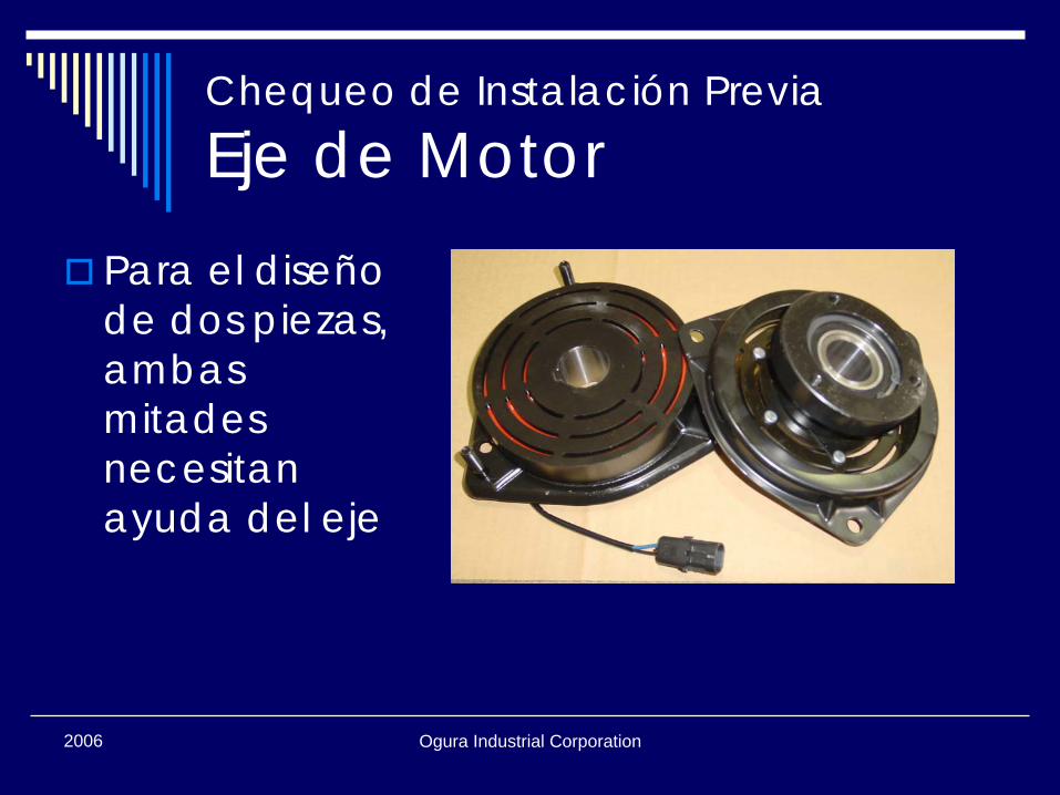
Eje de MotorPara el diseño de dos piezas, ambas mitades necesitan ayuda del eje
Ogura Industrial Corporation2006
Chequeo de Instalación Previa
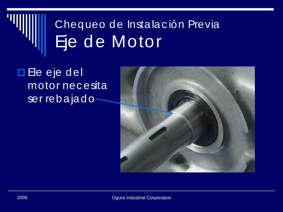
Eje de MotorEle eje del motor necesita ser rebajado
Ogura Industrial Corporation2006
Chequeo de Instalación Previa
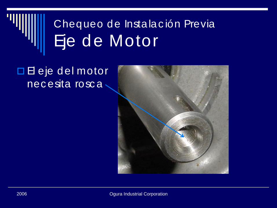
Eje de MotorEl eje del motor necesita rosca
Ogura Industrial Corporation2006
Chequeo de Instalación PreviaLongitud y Altura de la Llave
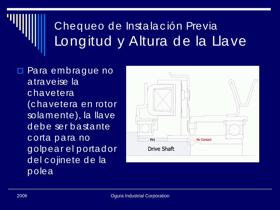
Para embrague no atraveise la chavetera(chavetera en rotor solamente), la llave debe ser bastante corta para no golpear el portador del cojinete de la polea
Ogura Industrial Corporation2006
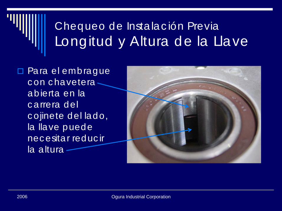
Chequeo de Instalación PreviaLongitud y Altura de la Llave
Para el embrague con chaveteraabierta en la carrera del cojinete del lado, la llave puede necesitar reducir la altura
Ogura Industrial Corporation2006
Chequeo de Instalación Previa
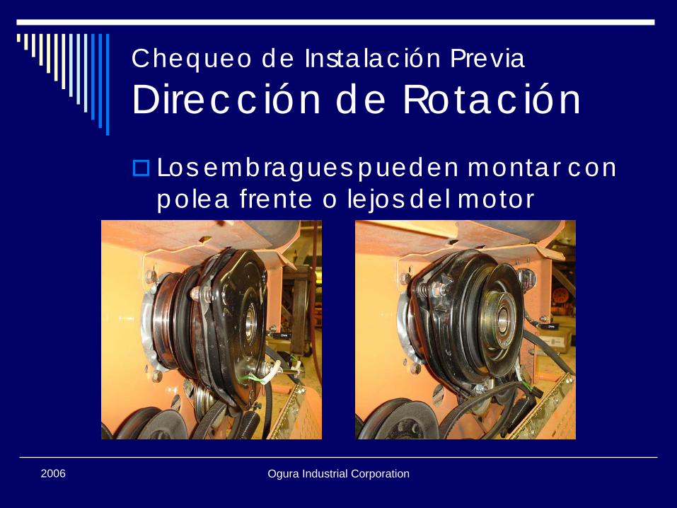
Dirección de RotaciónLos embragues pueden montar con polea frente o lejos del motor
Ogura Industrial Corporation2006
Chequeo de Instalación Previa
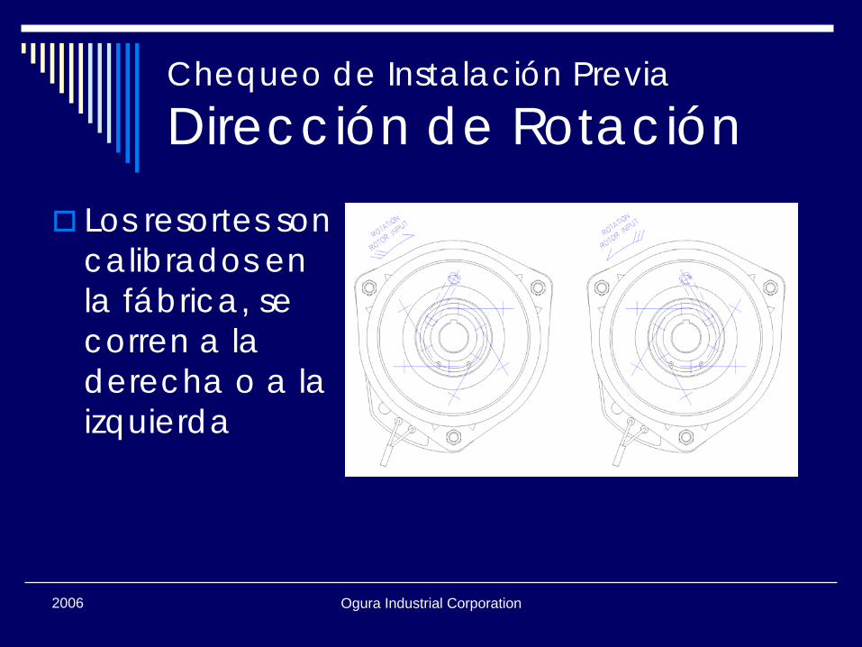
Dirección de RotaciónLos resortes son calibrados en la fábrica, se corren a la derecha o a la izquierda
Ogura Industrial Corporation2006
Chequeo de Instalación Previa
Dirección de RotaciónVerifique la dirección de la rotación para verificar la dirección del resorte correctoLos resortes deben operar en tensión no compresión (la mayoría de motores giran a la izquierda)
Ogura Industrial Corporation2006
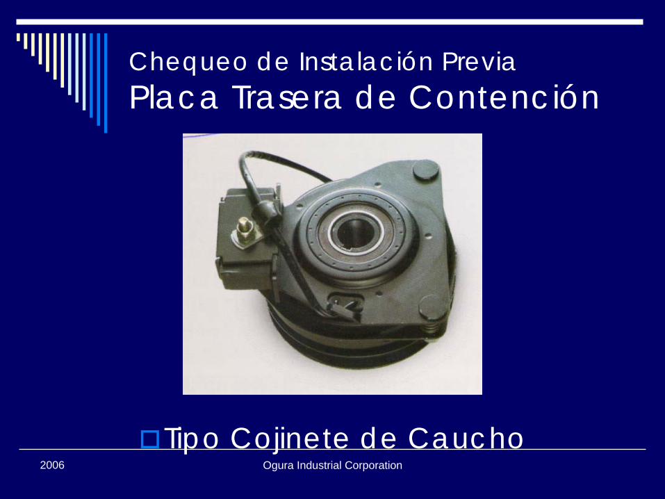
Chequeo de Instalación PreviaPlaca Trasera de Contención
La Placa Trasera de Contención de PTO necesita resistir la fuerza de freno
Esto puede ser 2 ~ 10 ft-lbs, dependiendo del tamaño del embrague
Ogura Industrial Corporation2006
Chequeo de Instalación PreviaPlaca Trasera de Contención
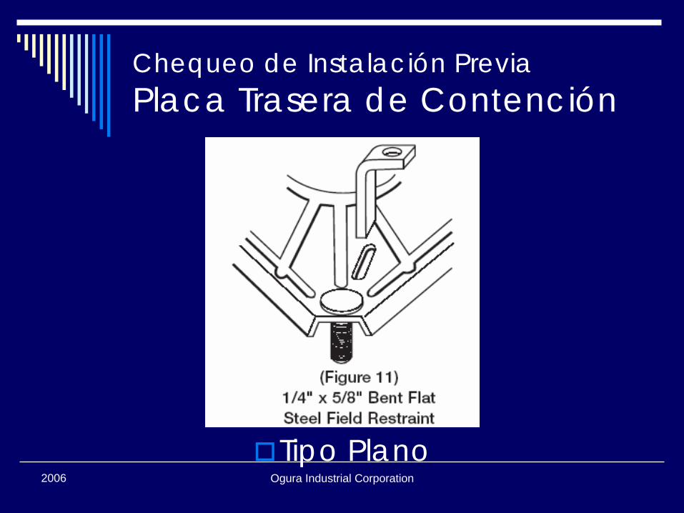
Tipo Plano
Ogura Industrial Corporation2006
Chequeo de Instalación PreviaPlaca Trasera de Contención
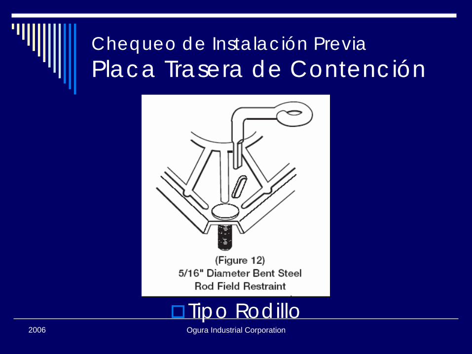
Tipo Rodillo
Ogura Industrial Corporation2006
Chequeo de Instalación PreviaPlaca Trasera de Contención
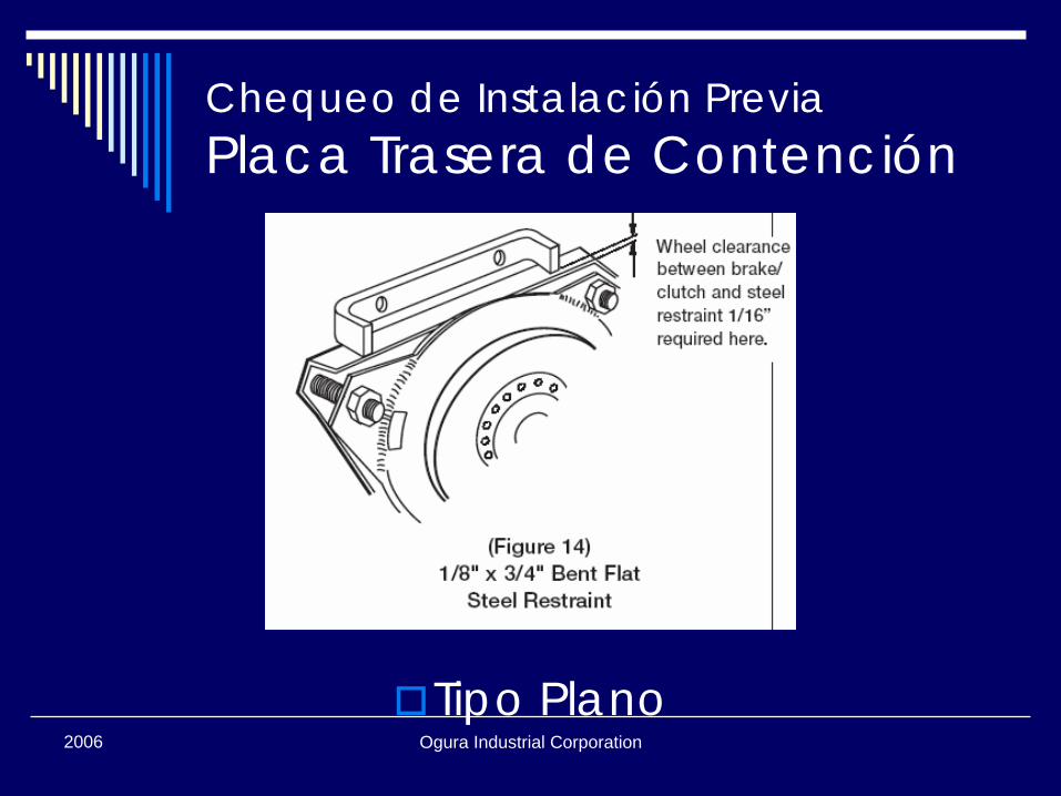
Tipo Plano
Ogura Industrial Corporation2006
Chequeo de Instalación PreviaPlaca Trasera de Contención
Tipo Cojinete de Caucho

2006 Ogura Industrial Corporation
Instalación
Ogura Industrial Corporation2006
Instalación de Embrague PTO① Verifique eje/polea apropiada para el embrague② Coloque llave en la chavetera del eje si se
requiere (algunos embragues tienen llave interna)
③ Deslice embrague en el eje④ Verifique buen contacto en la cara del anillo
interno de la caja de bolas⑤ Ajuste perno central y arandela⑥ Verifique la placa trasera de contención leve
libertad, axial y radial⑦ Conectar embrague⑧ Bruñir (asentar) embrague
Ogura Industrial Corporation2006
Instalación de Embrague PTO #1
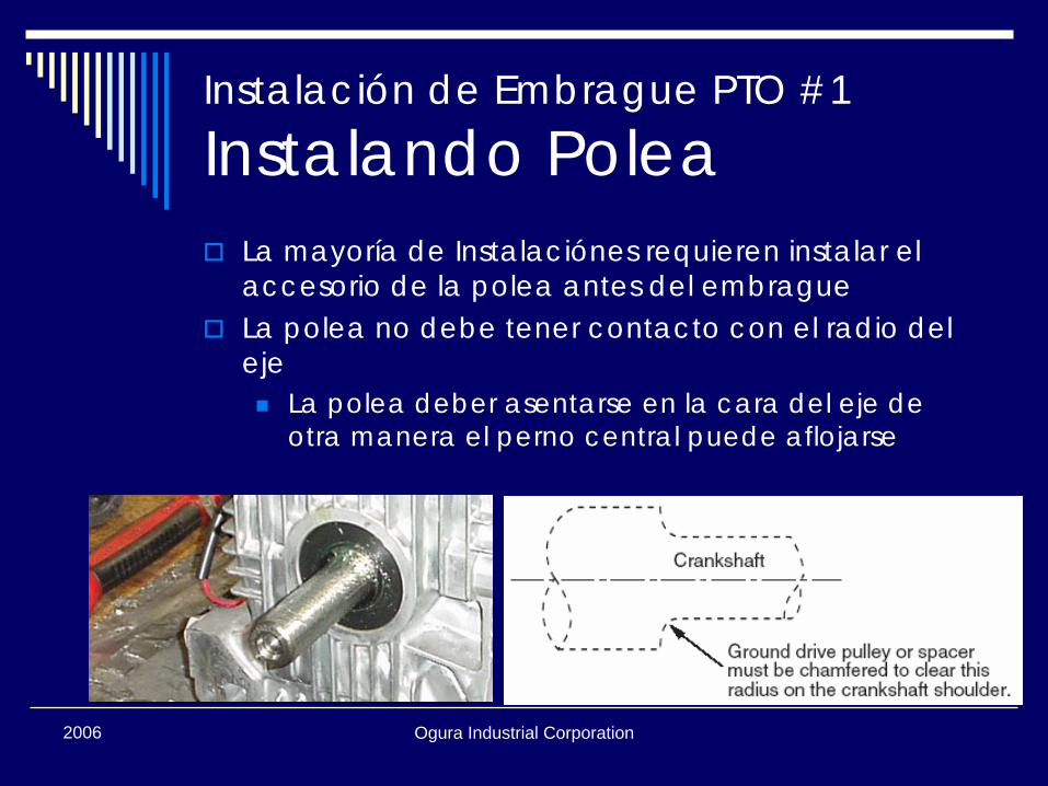
Instalando PoleaLa mayoría de Instalaciónes requieren instalar el accesorio de la polea antes del embragueLa polea no debe tener contacto con el radio del eje
La polea deber asentarse en la cara del eje de otra manera el perno central puede aflojarse
Ogura Industrial Corporation2006
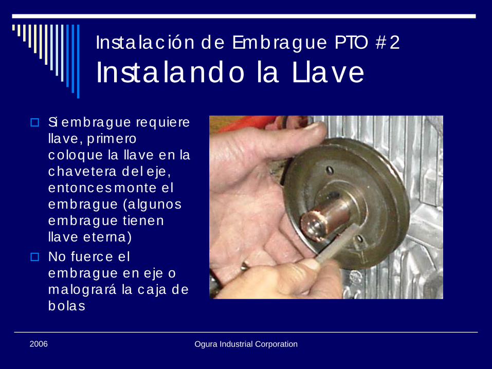
Instalación de Embrague PTO #2
Instalando la LlaveSi embrague requiere llave, primero coloque la llave en la chavetera del eje, entonces monte el embrague (algunos embrague tienen llave eterna)No fuerce el embrague en eje o malogrará la caja de bolas
Ogura Industrial Corporation2006
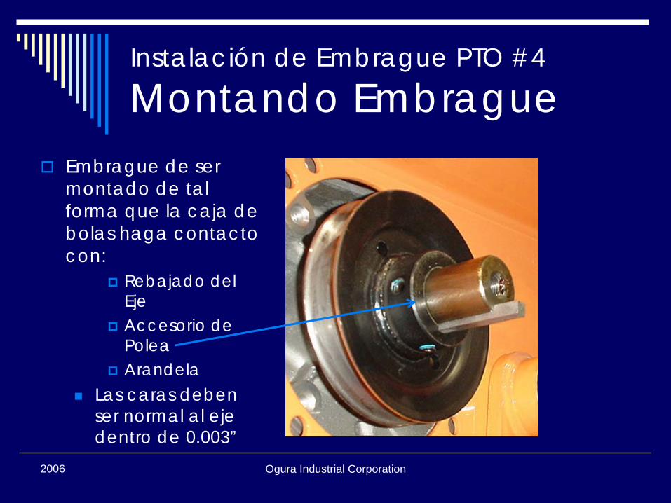
Instalación de Embrague PTO #4
Montando EmbragueEmbrague de ser montado de tal forma que la caja de bolas haga contacto con:
Rebajado del EjeAccesorio de PoleaArandela
Las caras deben ser normal al eje dentro de 0.003”
Ogura Industrial Corporation2006
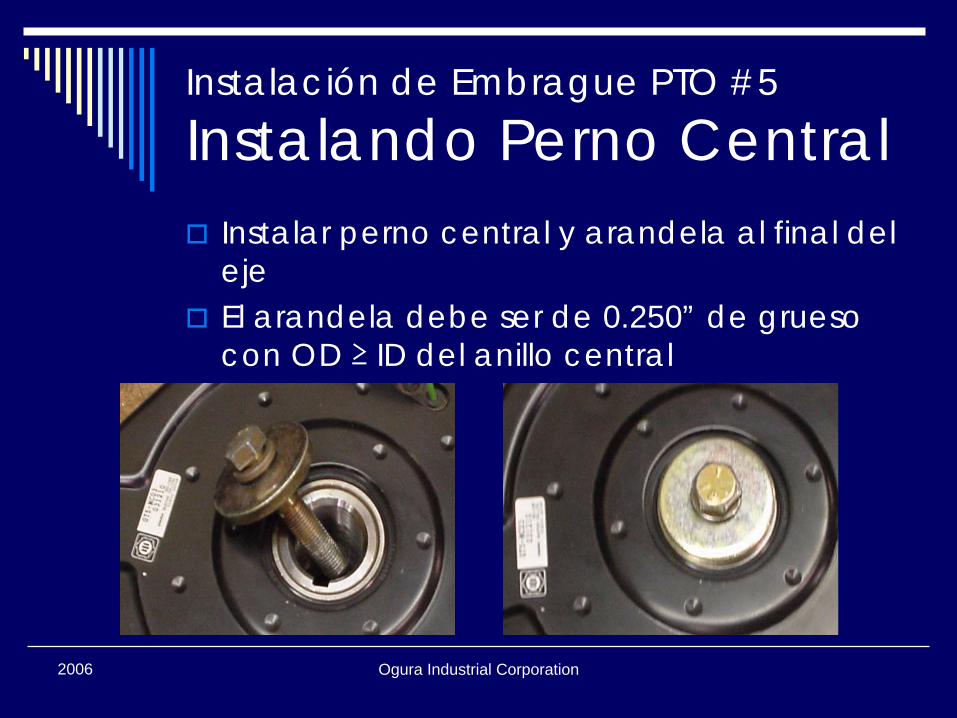
Instalación de Embrague PTO #5
Instalando Perno CentralInstalar perno central y arandela al final del ejeEl arandela debe ser de 0.250” de grueso con OD ≥ ID del anillo central
Ogura Industrial Corporation2006
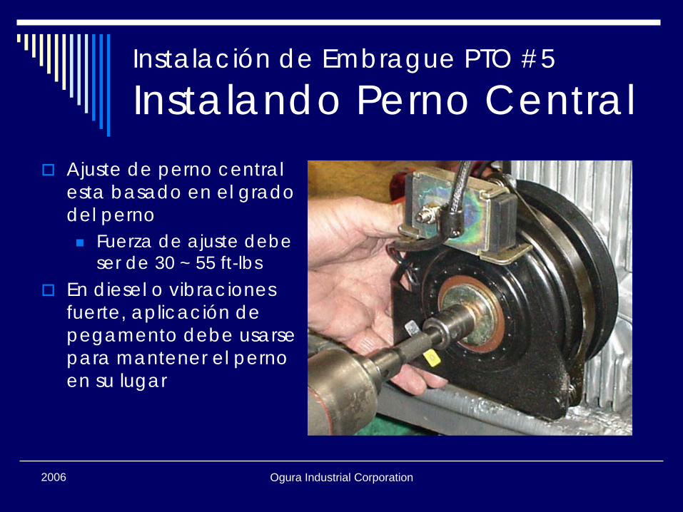
Instalación de Embrague PTO #5
Instalando Perno CentralAjuste de perno central esta basado en el grado del perno
Fuerza de ajuste debe ser de 30 ~ 55 ft-lbs
En diesel o vibraciones fuerte, aplicación de pegamento debe usarse para mantener el perno en su lugar
Ogura Industrial Corporation2006
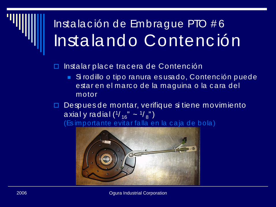
Instalación de Embrague PTO #6
Instalando ContenciónInstalar place tracera de Contención
Si rodillo o tipo ranura es usado, Contención puede estar en el marco de la maguina o la cara del motor
Despues de montar, verifique si tiene movimiento axial y radial (1/16” ~ 1/8”)(Es importante evitar falla en la caja de bola)
Ogura Industrial Corporation2006
Instalación de Embrague PTO #7
Conectando EmbragueConecte el terminal del embrague al alambre principal correspondienteConecte la electricidad a la cortacéspedes sin prender el motor, si es posiblePrenda PTO interruptor para verificar si el embrague trabaja
El embrague hará un sonido (click) si funciona
Ogura Industrial Corporation2006
Instalación de Embrague PTO #8
Bruñir¿Que es?
Bruñir/Asentar superficies de armadura y rotor¿Porque es importante?
Para lograr mejor arranque¿Como se hace?
El embrague 20 ~ 50 veces corrido levemente a 2.000 rpm
Ogura Industrial Corporation2006
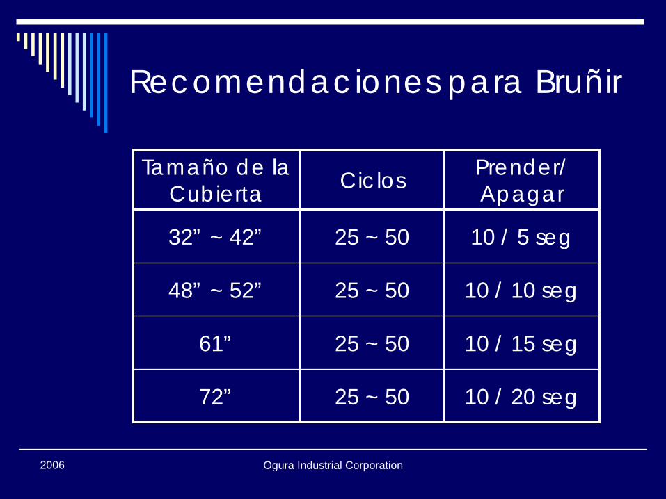
Recomendaciones para Bruñir
Tamaño de la Cubierta Ciclos Prender/
Apagar
32” ~ 42” 25 ~ 50 10 / 5 seg
48” ~ 52” 25 ~ 50 10 / 10 seg
61” 25 ~ 50 10 / 15 seg
72” 25 ~ 50 10 / 20 seg

2006 Ogura Industrial Corporation
Mantenimiento
Ogura Industrial Corporation2006
MantenimientoLa mayoría de las partes de embrague no requieren mantenimiento y no se puede reemplazar
Cojinetes son sellados por embragueArmadura, el rotor, y freno se gastan uniformemente y no se puede reemplazar individualmenteBobina no puede ser removida
Ogura Industrial Corporation2006
Ajuste por DesgasteTodo los Ogura embragues de una pieza son calibrados de fábrica(no se necesita ajuste inicial)Cuando embragues ajustables se gastan ellos pueden ser reajustados para extender la vida general
Ogura Industrial Corporation2006
Ajuste por DesgasteSi el embrague no jala o no continua jalando cuando se calienta el espacia de aire puede necesitar ajustePara hacer los ajustes, quitando PTO del cortacéspedes puede ser mas facilEquipo necesario
0.015”~0.022” calibrador9/16” llave de boca
Ogura Industrial Corporation2006
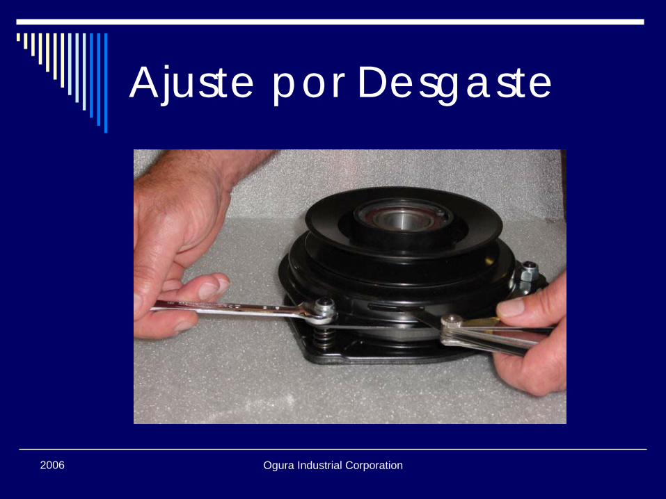
Ajuste por DesgasteIdentifique el modelo de embrague en la etiqueta localizada en la espalda del embragueHay tres ranuras de inspección en el frenoColoque el calibrador en la ranura entre armdura y rotorApriete suavement el freno hasta que armdura y rotor contacten el calibrador
Ogura Industrial Corporation2006
Ajuste por DesgasteCasi todos embragues de Ogura utilizan perno de freno 24UNF, asi una vuelta del perno iguala a aproximadamente 0.04” de movimiento axial(solor por referencia: el calibrador se require)
Ogura Industrial Corporation2006
Ajuste por Desgaste
Ogura Industrial Corporation2006
Ajuste por Desgaste
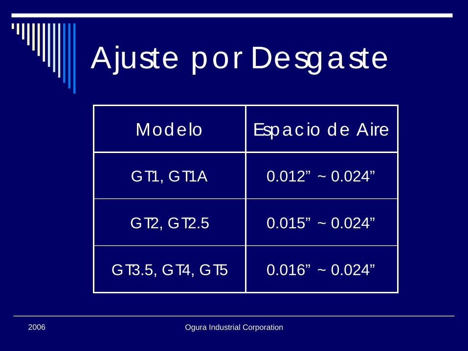
Modelo Espacio de Aire
GT1, GT1A 0.012” ~ 0.024”
GT2, GT2.5 0.015” ~ 0.024”
GT3.5, GT4, GT5 0.016” ~ 0.024”
Ogura Industrial Corporation2006
Ajuste por DesgasteAjustando el espacio mas pequeño aumentara el ciclo de vida entre ajustesCuidado: no ajuste el espacio debajo del mínimo o el embrague se puede dañarUna vez que el espacio se ajuste gire armadura y rotor, revise el espacio con el calibrador y haga los ajustes necesarios
Ogura Industrial Corporation2006
Ajuste por DesgasteAplique al embrague el voltaje completoGire armadura y rotor para no verificar contacto entre manto de armadura y frenoSi hay el contacto, afloje los tornios del freno y pruebe nuevamente hasta que no halla contacto

2006 Ogura Industrial Corporation
GraciasTODO DE UN EMBRAGUE DE OGURA TRABAJA
Para mas información sobre embragues de Ogura, visitenos en la internetwww.ogura-clutch.com