Embed Size (px)
Citation preview
17
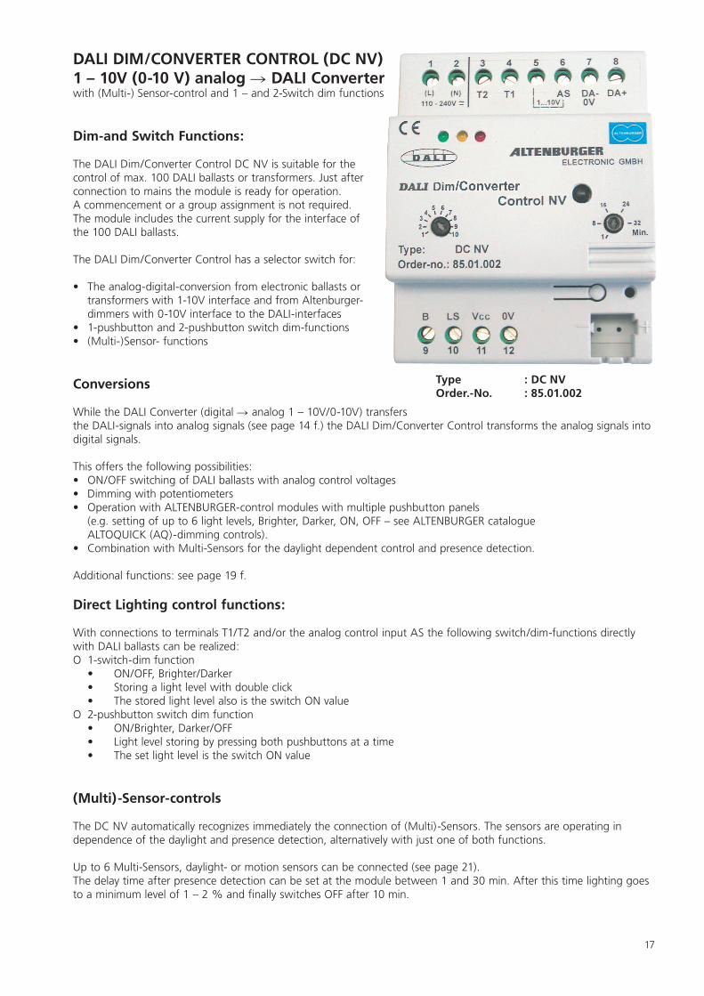
Type : DC NV Order.-No. : 85.01.002
DALI DIM/CONVERTER CONTROL (DC NV) 1 – 10V (0-10 V) analog DALI Converterwith (Multi-) Sensor-control and 1 – and 2-Switch dim functions
Dim-and Switch Functions:
The DALI Dim/Converter Control DC NV is suitable for the control of max. 100 DALI ballasts or transformers. Just after connection to mains the module is ready for operation. A commencement or a group assignment is not required. The module includes the current supply for the interface of the 100 DALI ballasts.
The DALI Dim/Converter Control has a selector switch for:
• The analog-digital-conversion from electronic ballasts or transformers with 1-10V interface and from Altenburger- dimmers with 0-10V interface to the DALI-interfaces
• 1-pushbutton and 2-pushbutton switch dim-functions• (Multi-)Sensor- functions
Conversions
While the DALI Converter (digital analog 1 – 10V/0-10V) transfers the DALI-signals into analog signals (see page 14 f.) the DALI Dim/Converter Control transforms the analog signals into digital signals.
This offers the following possibilities: • ON/OFF switching of DALI ballasts with analog control voltages• Dimming with potentiometers • Operation with ALTENBURGER-control modules with multiple pushbutton panels
(e.g. setting of up to 6 light levels, Brighter, Darker, ON, OFF – see ALTENBURGER catalogue ALTOQUICK (AQ)-dimming controls).
• Combination with Multi-Sensors for the daylight dependent control and presence detection.
Additional functions: see page 19 f.
Direct Lighting control functions:
With connections to terminals T1/T2 and/or the analog control input AS the following switch/dim-functions directly with DALI ballasts can be realized:O 1-switch-dim function
• ON/OFF, Brighter/Darker • Storing a light level with double click • The stored light level also is the switch ON value
O 2-pushbutton switch dim function • ON/Brighter, Darker/OFF • Light level storing by pressing both pushbuttons at a time • The set light level is the switch ON value
(Multi)-Sensor-controls
The DC NV automatically recognizes immediately the connection of (Multi)-Sensors. The sensors are operating in dependence of the daylight and presence detection, alternatively with just one of both functions.
Up to 6 Multi-Sensors, daylight- or motion sensors can be connected (see page 21).The delay time after presence detection can be set at the module between 1 and 30 min. After this time lighting goes to a minimum level of 1 – 2 % and finally switches OFF after 10 min.
18
Technical Data DALI Dim/Converter Control (DC NV)
Designation : DALI Dim/Converter Control NVType : DC NVOrder-No. : 85.01.002
Power supply : 110V-240V AC 50/60Hz, 110V-240V DCOwn consumption : approx. 0,7 - 5,8W, depending on the loadProtection : external 16AAmbient temperature : max. 45°C
Protective class : II (protective isolation)Protective type : IP20Contamination degree : 2 (dry, non-conductive)
Delay time setting : adjustable between 1 and 30 minutes. After this time the light level is reduced to 1-2 % and finally switches OFF after approx. 10 min.
DALI - interface : according to DALI-specification, interface poled Power supply for max. 100 DALI ballasts, approx. 200mA/13V DC (Uo approx. 15V DC) - Ik<250mA DC, max. 22,5V DC - electronic current limitation,
pushbutton inputs : 2 pushbutton inputs (<6V DC) (normally open contact) Terminal T1/T2AnalogControl input : voltage input (analog 0-10V/DC) Terminal ASTerminal 5 (1-10V) : internal power supply (approx. 450 µA) for the bridge at 1..10V interface
(for operations in systems with 1…10V interface, potentiometers for another manual control an external bridge from terminal 6 to terminal 5 has to be made)
Sensor inputs : 1 Light input (analog <5V DC), 1 motion input (<5V DC) Terminal LS/BSensor supply : approx. 10V/18mA DC (supply for the sensors) Terminal VccSensors : max. 6 sensors in parallel (see sensors and manual)
DALI–interfaces and control inputs (pushbutton inputs /sensoric/analog signals) have no basic isolation, no protective low-voltage
Indicators at the module: 3x LEDs, indicating the working conditions of the module,1xselector switch for the different functions
Controls : 1xTrimmer/Potentiometer for the setting of the delay time (1-30 min.) 1xpushbutton: optional
Terminals : Screw terminals for solid and litz wires with sleeve (0,25-5,0mm2)Supply : L, N Terminal No. (1/2)Control inputs : T2, T1, AS Terminal No. (3, 4, 5,6)DALI-interface : DA+ DA- Terminal No. (8, 7)Sensors : B, LS, Vcc Terminal No. (9, 10, 11)0V (DA-) : 0V Terminal No. (7, 12) (0V and DA are internally connected)
Wire length: : max. 100m - DALI-wires max. 300m with 1,5mm2 or accord. to Table (distance of controller to DALI ballasts, -converter)
Wire section in mm2 2x0,5 2x0,75 2x1,0 2x1,5
Wire length (distance) in m 100 150 200 300
- DALI- and supply wires must be separated from the control wires (not in one cable) - Wiring : The respectively requirements for installations (wiring, isolation, protection/ minimum sections)
have to be observed.Housing : Isolation housing for DIN rail systemsDimensions : WxHxD=72x90x64mmWeight : approx. 200gDesignation : CE, DALIwiring : according to wiring diagrams and print at the moduleExcept to the supply terminals no supply potentials may be connected to the module.All potentials for the control and operation may have a basis isolation.
19
Selection of the different functions at the DALI DIM/CONVERTER CONTROLThe following lighting control and converter functions can be selected with the switch at the front of the module:
Position 1:
Conversion of analog signals 1 – 10V (0-10V) to digital DALI-signals (input terminals AS and T1)
• ON/OFF switching via a switch contact (relays, contact/switch), connection to terminal T1 o contact closed = ON; contact open = OFF
• Control of the brightness via the analog voltage input [AS] o the respective voltage (1...10V) is the switch ON or control value
• Switching of the lighting through a motion sensor if the contact at terminal [T1] is closed• Switching of the lighting in dependence of the daylight through a light sensor if the contact at [T1] is closed• Switching of the lighting through a multi-sensor (Light sensor and motion detector in one)
o Automatic switch ON if daylight falls below the set light level and if motion is recognized: contact T1 = closed. o No automatic switch ON if motion is recognized, daylight however exceeds the set light level.
Position 2:
Analog control without switch contact: Conversion from 1...10V (0 … 10V) to the digital DALI-interface with ON/OFF only through an analog control voltage (input terminal [AS])
• ON/OFF switching through an analog control voltage [terminal AS] o voltage >1,4V = ON; voltage <1,4 = OFF
• Control of the brightness through the analog voltage input [terminal AS] o voltage >1,4V is the Switch ON or the control value
• If a motion sensor is connected: switch ON at motion, if the voltage at [terminal AS] >1,4V • Automatic switch ON through a light sensor if the daylight falls below the set light level and the voltage at [terminal AS] > 1,4V • Multi-Sensor-control (combined light and motion sensor):
o Automatic switch ON if the daylight falls below the set light level and motion is recognized (volt-age at terminal AS >1,4V) o No automatic switch ON if motion is recognized, however daylight exceeds the set light level.
Position 3:
1-pushbutton switch dim function: control input = terminal T1
• ON/OFFswitching through pushbutton (normally open contact) at [T1] o Short pushing: ON/OFF
• Control of the brightness through pushbutton (normally open contact) at [T1] o Continuously pressing the button: lighting goes to brighter-darker-brighter
• Light level setting at [T1]: o As soon as the required light level to be kept constant is achieved during the brighter-darker-
brighter operation a double click stores the value as switch ON or control value being kept constant. The set light level is indicated through a short flash of the lighting.
• Connection of a motion sensor: lighting automatically switches ON to the set light level as soon as motion is recognized.• Connection of a light sensor: automatic switch ON into the set light level as soon as daylight falls below this level. • Multi-Sensor control (light- and motion-depending):
o Automatic switch ON if daylight falls below the set light level o No automatic switch ON if motion is recognized, daylight however exceeds the set light level
20
Position 4:
2-pushbutton-switch-dim function: control input terminals T1/T2
• ON/Brighter with pushbutton (normally open contact) at control input [T1]o Short touch: ON; continuous touch: brighter
• Darker/Off through a pushbutton (normally open contact) at control input [T2]o Continuously pressing = darker - short pressing = off
• Light level setting for a constant light control through light sensor and control inputs [T1/T2]o Continuously pressing both buttons [T1/T2] for > 3 sec.: The setting of the light level to be kept constant is signalized through a short flash of the con-nected lighting o The stored light level is the automatic switch ON or control value
• With the connection of a motion sensor: automatic switch ON of the lighting if motion is recognized • With the connection of a light sensor: automatic switch ON if daylight falls below the set light level • With the connection of a multi-sensor (light- and motion sensor in one):
o Automatic switch ON if daylight falls below the set light level and motion is recognizedo No automatic switch ON if daylight exceeds the set light level although motion is recognized.
Position 5:
1-pushbutton switch dim function with interlocking of the automatic switch ON control:
• Function identical with position 3, however no automatic switch ON if daylight falls below the set light level.
o switch ON to be made manually.
Position 6:
2-pushbutton switch dim function with interlocking of the automatic switch ON control:
• Function identical with position 4, however no automatic switch ON if daylight falls below the set light level.
o switch ON to be made manually
The changing of different positions is possible only after power ON !
Messages
OperationThe green LED signalizes readiness for operation, the yellow LED indicates DALI-signals.
DALI-Faults If DALI ballasts are not connected or DALI-wires are interrupted, the red LED flashes twice. The double flash continues unless the fault is removed.
DALI short circuitIn case of a short circuit on DALI-connections the red LED flashes three times.This is repeated unless the fault is removed.
21
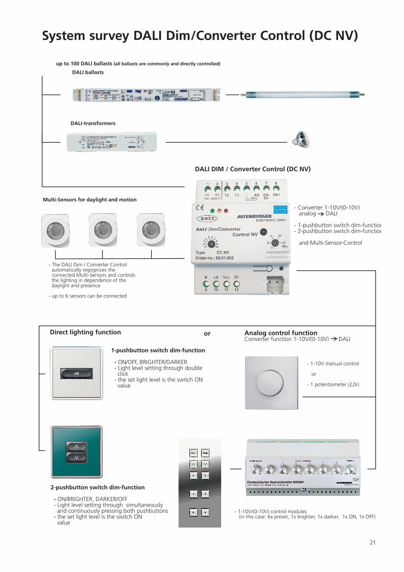
System survey DALI Dim/Converter Control (DC NV)
- 1-10V manual control or
- 1 potentiometer (22k)
- 1-10V/(0-10V) control modules (in this case: 6x preset, 1x brighter, 1x darker, 1x ON, 1x OFF)
up to 100 DALI ballasts (all ballasts are commonly and directly controlled)
- Converter 1-10V/(0-10V) analog DALI
- 1-pushbutton switch dim-function - 2-pushbutton switch dim-function
and Multi-Sensor-Control
DALI DIM / Converter Control (DC NV)
DALI ballasts
- The DALI Dim / Converter Control automatically regognizes the connected Multi-Sensors and controls the lighting in dependence of the daylight and presence
- up to 6 sensors can be connected
Multi-Sensors for daylight and motion
Analog control functionConverter function 1-10V/(0-10V) DALI
Direct lighting function or
1-pushbutton switch dim-function
- ON/OFF, BRIGHTER/DARKER - Light level setting through double click - the set light level is the switch ON value
2-pushbutton switch dim-function
- ON/BRIGHTER, DARKER/OFF - Light level setting through simultaneously and continuously pressing both pushbuttons - the set light level is the switch ON value
DALI-transformers
22
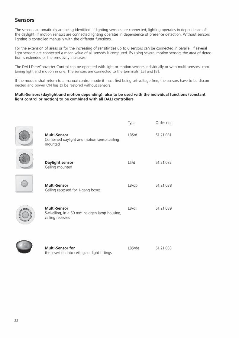
Sensors
The sensors automatically are being identified. If lighting sensors are connected, lighting operates in dependence of the daylight. If motion sensors are connected lighting operates in dependence of presence detection. Without sensors lighting is controlled manually with the different functions.
For the extension of areas or for the increasing of sensitivities up to 6 sensors can be connected in parallel. If several light sensors are connected a mean value of all sensors is computed. By using several motion sensors the area of detec-tion is extended or the sensitivity increases.
The DALI Dim/Converter Control can be operated with light or motion sensors individually or with multi-sensors, com-bining light and motion in one. The sensors are connected to the terminals [LS] and [B].
If the module shall return to a manual control mode it must first being set voltage free, the sensors have to be discon-nected and power ON has to be restored without sensors.
Multi-Sensors (daylight-and motion depending), also to be used with the individual functions (constant light control or motion) to be combined with all DALI controllers
Type Order no.:
Multi-SensorCombined daylight and motion sensor,ceiling mounted
LBS/d 51.21.031
Daylight sensorCeiling mounted
LS/d 51.21.032
Multi-SensorCeiling recessed for 1-gang boxes
LB/db 51.21.038
Multi-SensorSwivelling, in a 50 mm halogen lamp housing, ceiling recessed
LB/dk 51.21.039
Multi-Sensor for the insertion into ceilings or light fittings
LBS/de 51.21.033
L
N
PE
Netz 110-240V AC (50/60Hz) DC
F116A
1 2
9 10
8
12 3
7L N
DALI Dim/Converter Control NV
DC NV 85.01.002
DA-
DA+DALI
DALI-EVGs
DA-/0V
DA+
11 4 5 6B LS Vcc 0V T2 T1 AS
Wahlschalter
Ein/Aus mit Schaltkontakt
1/10
L
N
PE
Netz 110-240V AC (50/60Hz) DC
F116A
1 2
9 10
8
12 3
7L N
DALI Dim/Converter Control NV
DC NV 85.01.002
DA-
DA+DALI
DALI-EVGs
DA-/0V
DA+
11 4 5 6B LS Vcc 0V T2 T1 AS
Wahlschalter
Ein/Aus mit Steuerspannung
2
23
L
N
PE
mains 110-240V AC (50/60Hz) DC
F116A
1 2
9 10
8
12 3
7L N
DALI Dim/Converter Control NV
DC NV 85.01.002
DA-
DA+DALI
DALI-modules
DA-/0V
DA+
11 4 5 6B LS Vcc 0V T2 T1 AS
Selector switch
On/Off with switch contact
1/10
L
N
PE
mains110-240V AC (50/60Hz) DC
F116A
1 2
9 10
8
12 3
7L N
DALI Dim/Converter Control NV
DC NV 85.01.002
DA-
DA+DALI
DALI-modules
DA-/0V
DA+
11 4 5 6B LS Vcc 0V T2 T1 AS
Selector switch
On/Off with control voltage
2
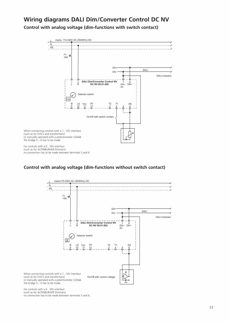
When connecting controls with a 1…10V interface(such as for EVG’s and transformers)or manually operated with a potentiometer (22k )the bridge 5 – 6 has to be made.
For controls with a 0…10V interface(such as for ALTENBURGER Dimmers)no connection has to be made between terminals 5 and 6.
Wiring diagrams DALI Dim/Converter Control DC NV
Control with analog voltage (dim-functions with switch contact)
Control with analog voltage (dim-functions without switch contact)
When connecting controls with a 1…10V interface(such as for EVG’s and transformers)or manually operated with a potentiometer (22k )the bridge 5 – 6 has to be made.
For controls with a 0…10V interface(such as for ALTENBURGER Dimmers)no connection has to be made between terminals 5 and 6.
L
N
PE
Netz 110-240V AC (50/60Hz) DC
F116A
1 2
9 10
8
12 3
7L N
DA-
DA+DALI
DALI-EVGs
DA-/0V
DA+
11 4 5 6B LS Vcc 0V T2 T1 AS
Wahlschalter
3-6
DALI Dim/Converter Control NV
DC NV 85.01.002
L
N
PE
Netz 110-240V AC (50/60Hz) DC
F116A
1 2
9 10
8
12 3
7L N
DA-
DA+DALI
DALI-EVGs
DA-/0V
DA+
11 4 5 6B LS Vcc 0V T2 T1 AS
Wahlschalter
Licht- u. Bewegungssensor
B LS Vcc 0V
Licht- u. Bewegungssensor
B LS Vcc 0V
max. 6 Sensoren parallel
LBS/d LS/dLBS/de LS/de
Typ:
1-6
braun
gelbweiß
grün
gews gn bn
DALI Dim/Converter Control NV
DC NV 85.01.002
L
N
PE
mains 110-240V AC (50/60Hz) DC
F116A
1 2
9 10
8
12 3
7L N
DALI Dim/Converter Control NV
DC NV 85.01.002
DA-
DA+DALI
DALI-modules
DA-/0V
DA+
11 4 5 6B LS Vcc 0V T2 T1 AS
Selector switch
light and motion sensor
B LS Vcc 0V
light and motion sensor
B LS Vcc 0V
max.6 Sensors in parallel
Type: LBS/d LS/dLBS/de LS/de
1-6/10
brown
yellow
white
green
gews gn bn
L
N
PE
mains 110-240V AC (50/60Hz) DC
F116A
1 2
9 10
8
12 3
7L N
DALI Dim/Converter Control NV
DC NV 85.01.002
DA-
DA+DALI
DALI-modules
DA-/0V
DA+
11 4 5 6B LS Vcc 0V T2 T1 AS
Selector switch
3-6
24
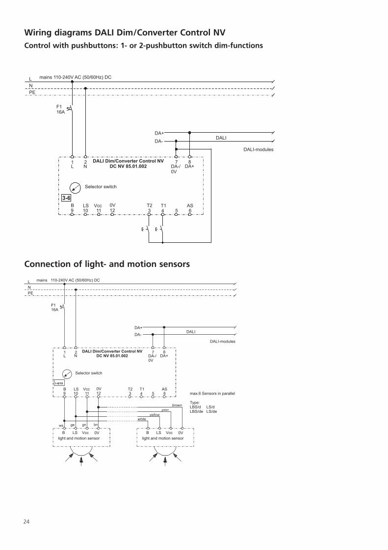
Wiring diagrams DALI Dim/Converter Control NV
Control with pushbuttons: 1- or 2-pushbutton switch dim-functions
Connection of light- and motion sensors
25
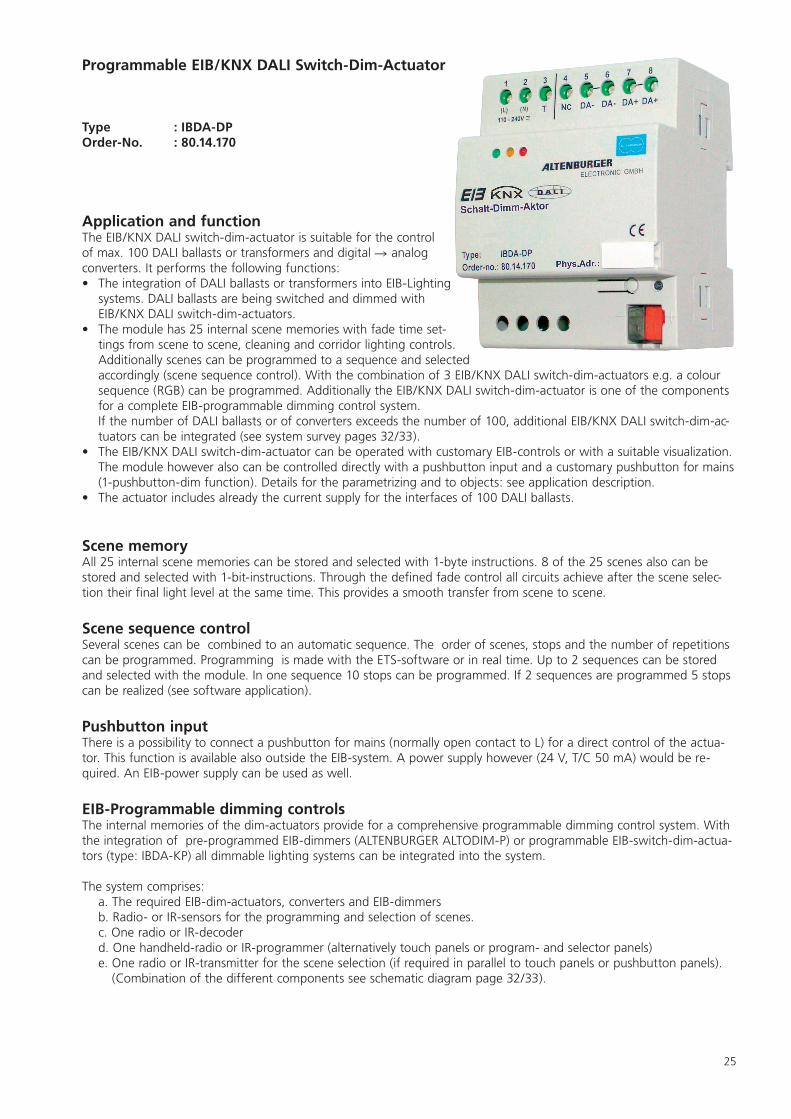
Programmable EIB/KNX DALI Switch-Dim-Actuator
Type : IBDA-DPOrder-No. : 80.14.170
Application and function The EIB/KNX DALI switch-dim-actuator is suitable for the control of max. 100 DALI ballasts or transformers and digital analog converters. It performs the following functions: • The integration of DALI ballasts or transformers into EIB-Lighting
systems. DALI ballasts are being switched and dimmed with EIB/KNX DALI switch-dim-actuators.
• The module has 25 internal scene memories with fade time set-tings from scene to scene, cleaning and corridor lighting controls. Additionally scenes can be programmed to a sequence and selected accordingly (scene sequence control). With the combination of 3 EIB/KNX DALI switch-dim-actuators e.g. a colour sequence (RGB) can be programmed. Additionally the EIB/KNX DALI switch-dim-actuator is one of the components for a complete EIB-programmable dimming control system. If the number of DALI ballasts or of converters exceeds the number of 100, additional EIB/KNX DALI switch-dim-ac-tuators can be integrated (see system survey pages 32/33).
• The EIB/KNX DALI switch-dim-actuator can be operated with customary EIB-controls or with a suitable visualization. The module however also can be controlled directly with a pushbutton input and a customary pushbutton for mains (1-pushbutton-dim function). Details for the parametrizing and to objects: see application description.
• The actuator includes already the current supply for the interfaces of 100 DALI ballasts.
Scene memoryAll 25 internal scene memories can be stored and selected with 1-byte instructions. 8 of the 25 scenes also can be stored and selected with 1-bit-instructions. Through the defined fade control all circuits achieve after the scene selec-tion their final light level at the same time. This provides a smooth transfer from scene to scene.
Scene sequence controlSeveral scenes can be combined to an automatic sequence. The order of scenes, stops and the number of repetitions can be programmed. Programming is made with the ETS-software or in real time. Up to 2 sequences can be stored and selected with the module. In one sequence 10 stops can be programmed. If 2 sequences are programmed 5 stops can be realized (see software application).
Pushbutton inputThere is a possibility to connect a pushbutton for mains (normally open contact to L) for a direct control of the actua-tor. This function is available also outside the EIB-system. A power supply however (24 V, T/C 50 mA) would be re-quired. An EIB-power supply can be used as well.
EIB-Programmable dimming controlsThe internal memories of the dim-actuators provide for a comprehensive programmable dimming control system. With the integration of pre-programmed EIB-dimmers (ALTENBURGER ALTODIM-P) or programmable EIB-switch-dim-actua-tors (type: IBDA-KP) all dimmable lighting systems can be integrated into the system.
The system comprises: a. The required EIB-dim-actuators, converters and EIB-dimmers
b. Radio- or IR-sensors for the programming and selection of scenes. c. One radio or IR-decoder d. One handheld-radio or IR-programmer (alternatively touch panels or program- and selector panels) e. One radio or IR-transmitter for the scene selection (if required in parallel to touch panels or pushbutton panels).
(Combination of the different components see schematic diagram page 32/33).