Embed Size (px)
Citation preview
Networks: Physical Layer 1
Physical Layer
Networks: Physical Layer 2
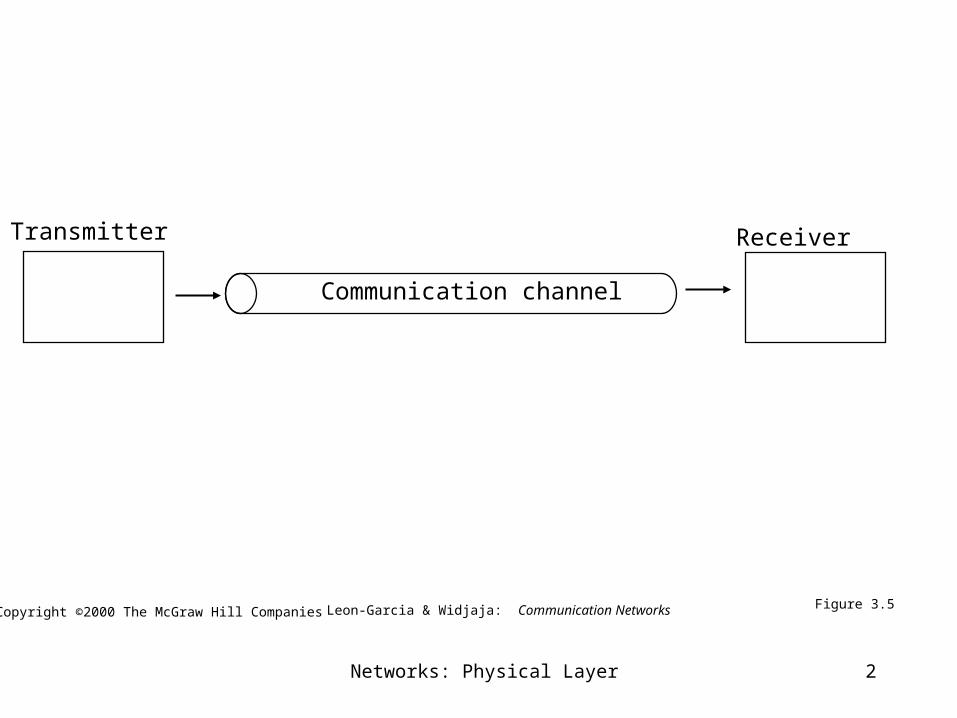
Receiver
Communication channel
Transmitter
Figure 3.5Copyright ©2000 The McGraw Hill Companies Leon-Garcia & Widjaja: Communication Networks
Networks: Physical Layer 3
Physical Layer definitions
• the time required to transmit a character depends on both the encoding method and the signaling speed (i.e., the modulation rate - the number of times/sec the signal changes its voltage)
• baud (D) - the number of changes per second
• bandwidth (W) - the range of frequencies that is passed by a channel. The transmitted signal is constrained by the transmitter and the nature of the transmission medium in cycles/sec (hertz)
• channel capacity (C) – the rate at which data can be transmitted over a given channel under given conditions.
Networks: Physical Layer 4
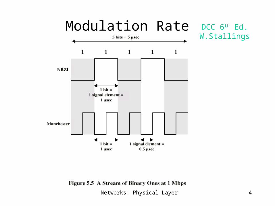
Modulation Rate DCC 6th Ed. W.Stallings

Networks: Physical Layer 5
Nyquist Theorem {assume a noiseless channel}
If an arbitrary signal is run through a low-pass filter of bandwidth W, the filtered signal can be completely reconstructed by making 2W samples/sec.
This implies for a signal of V discrete levels,
Note – a higher sampling rate is pointless because higher frequency signals have been filtered out.
Max. data rate :: C = 2W log 2 (V) bits/sec.

Networks: Physical Layer 6
f0 W
A(f)
(a) Lowpass and idealized lowpass channel
(b) Maximum pulse transmission rate is 2W pulses/second
0 Wf
A(f)1
Channel
tt
Figure 3.11Copyright ©2000 The McGraw Hill Companies Leon-Garcia & Widjaja: Communication Networks

Networks: Physical Layer 7
Voice-grade phone line
1. W = 4000 Hz
2W = 8000 samples/sec.
sample every 125 microseconds!!
2. D = 2400 baud
V = each pulse encodes 16 levels
C = 2W log 2 (V) = D x log 2 (V)
= 2400 x 4 = 9600 bps.
Networks: Physical Layer 8
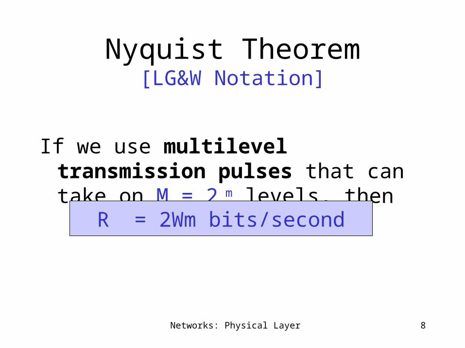
Nyquist Theorem[LG&W Notation]
If we use multilevel transmission pulses that can take on M = 2 m levels, then
R = 2Wm bits/second

Networks: Physical Layer 9
Ak
Bk
4 “levels”/ pulse2 bits / pulse2D bits per second
Ak
Bk
16 “levels”/ pulse4 bits / pulse4D bits per second
Figure 3.34
Signal Constellations
Copyright ©2000 The McGraw Hill Companies Leon-Garcia & Widjaja: Communication Networks
Note – textbook uses W instead of D in this figure!!

Networks: Physical Layer 10
signal noise signal + noise
signal noise signal + noise
HighSNR
LowSNR
SNR = Average Signal Power
Average Noise Power
SNR (dB) = 10 log10 SNR
t t t
t t t
Figure 3.12Copyright ©2000 The McGraw Hill Companies Leon-Garcia & Widjaja: Communication Networks
Networks: Physical Layer 11
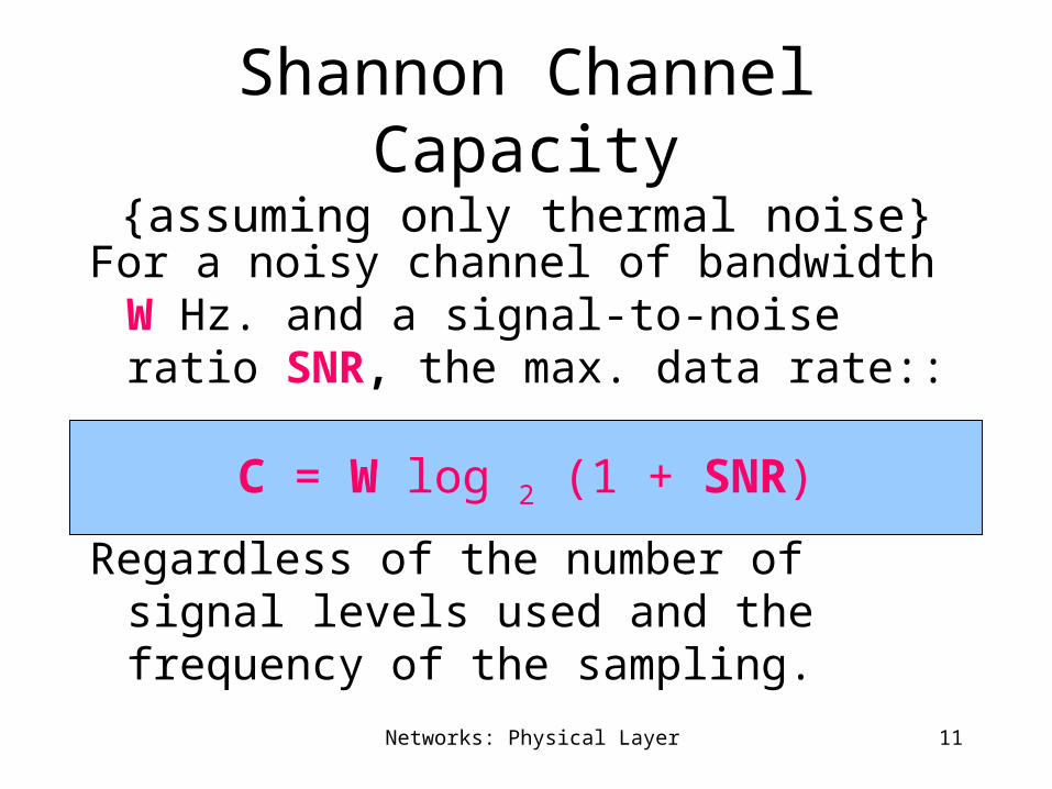
Shannon Channel Capacity{assuming only thermal noise}
For a noisy channel of bandwidth W Hz. and a signal-to-noise ratio SNR, the max. data rate::
Regardless of the number of signal levels used and the frequency of the sampling.
C = W log 2 (1 + SNR)
Networks: Physical Layer 12
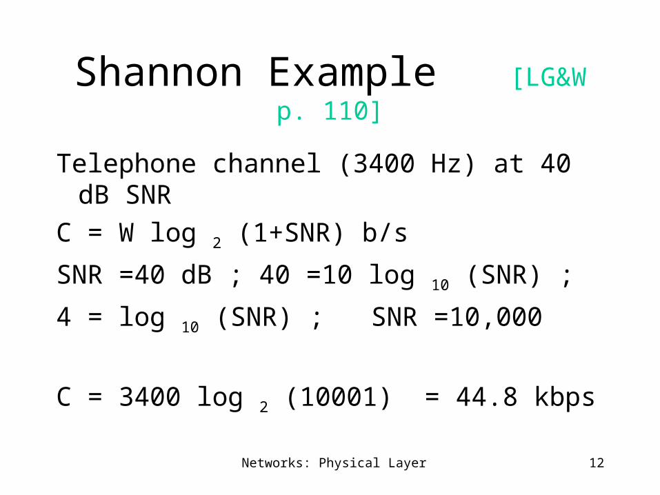
Shannon Example [LG&W p. 110]
Telephone channel (3400 Hz) at 40 dB SNR
C = W log 2 (1+SNR) b/s
SNR =40 dB ; 40 =10 log 10 (SNR) ;
4 = log 10 (SNR) ; SNR =10,000
C = 3400 log 2 (10001) = 44.8 kbps

Networks: Physical Layer 13
Data Communications ConceptsAnalog and Digital Data [Stalling’s Discussion]
Analog and digital correspond roughly to continuous and discrete. These two terms can be used in three contexts:
1. data:: entities that convey meaning.analog – voice and video are continuously
varying patterns of intensitydigital - take on discrete values (e.g., integers,
ASCII text)Data are propagated from one point to another by means
of electrical signals.

Networks: Physical Layer 14
Analog and Digital Signaling
signals:: electric or electromagnetic encoding of data.
2. signaling :: is the act of propagating the signal along a suitable medium.
Analog signal – a continuously varying electromagnetic wave that may be propagated over a variety of medium depending on the spectrum (e.g., wire, twisted pair, coaxial cable, fiber optic cable and atmosphere or space propagation).
Networks: Physical Layer 15
Analog and Digital Signaling
digital signal – a sequence of voltage pulses that may be transmitted over a wire medium.
Note – analog signals to represent analog data and digital signals to represent digital data are not the only possibilities.
Networks: Physical Layer 16
Signals DCC 6th Ed. W.Stallings
• Means by which data are propagated• Analog
– Continuously variable– Various media
• wire, fiber optic, space
– Speech bandwidth 100Hz to 7kHz– Telephone bandwidth 300Hz to 3400Hz– Video bandwidth 4MHz
• Digital– Use two DC components
Networks: Physical Layer 17
Analog and Digital Signaling
• Digital data can be represented by analog signals using a modem (modulator/demodulator).
The digital data is encoded on a carrier frequency.
• Analog data can be represented by digital signals using a codec (coder-decoder).

Networks: Physical Layer 18
Analog Signals Carrying Analog and Digital Data DCC 6th Ed. W.Stallings
Networks: Physical Layer 19
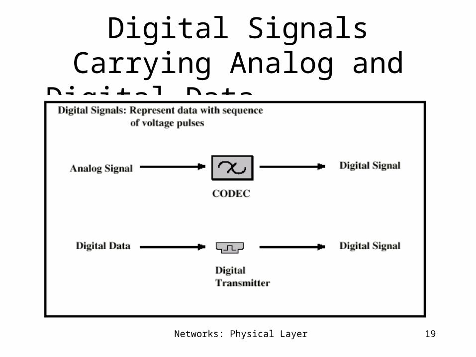
Digital Signals Carrying Analog and Digital Data DCC 6th Ed. W.Stallings
Networks: Physical Layer 20
Analog and Digital Signaling Comparison
• Digital signaling is:– Cheaper– Less susceptible to noise interference– Suffers more attenuation.
Networks: Physical Layer 21
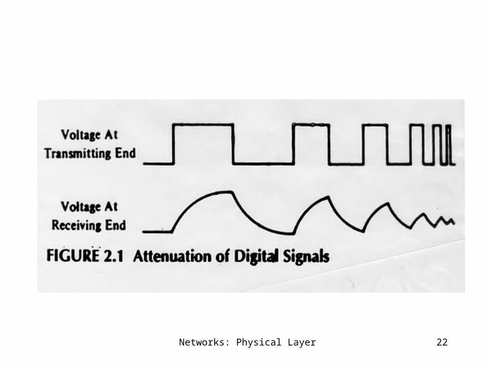
Attenuation
attenuation of a signal:: the reduction or loss of signal strength (power) as it transferred across a system.
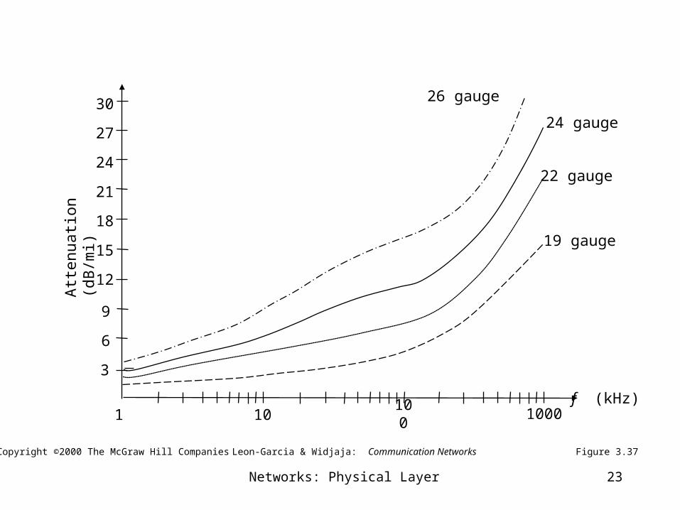
Attenuation is an increasing function of frequency.
The strength of the received signal must be strong enough for detection and must be higher than the noise to be received without error.
Networks: Physical Layer 22
Networks: Physical Layer 23
Att
enua
tion
(dB
/mi)
f (kHz)
19 gauge
22 gauge
24 gauge
26 gauge
6
12
3
9
15
18
21
24
27
30
1 10 100 1000
Figure 3.37Copyright ©2000 The McGraw Hill Companies Leon-Garcia & Widjaja: Communication Networks

Networks: Physical Layer 24
Analog and Digital Transmissions
{Stalling’s third context}
3. Transmissions :: communication of data by the propagation and processing of signals.
– Both analog and digital signals may be transmitted on suitable transmission media.
– [Stalling’s argument] the way the signals are “treated” is a a function of the transmission system and here lies the crux of the distinction between transmission types.

Networks: Physical Layer 25
(a) Analog transmission: all details must be reproduced accurately
Sent
Sent
Received
Received
• e.g digital telephone, CD Audio
(b) Digital transmission: only discrete levels need to be reproduced
• e.g. AM, FM, TV transmission
Figure 3.6Copyright ©2000 The McGraw Hill Companies Leon-Garcia & Widjaja: Communication Networks

Networks: Physical Layer 26
Networks: Physical Layer 27
Analog Transmissions
Analog transmission :: a means of transmitting analog signals without regard to their content (i.e., the signals may represent analog data or digital data).
transmissions are attenuated over distance.
Analog signal – the analog transmission system uses amplifiers to boost the energy in the signal.
Networks: Physical Layer 28
Analog Transmissions
Amps boost the energy amplifies the signal and amplifies the noise
The cascading of amplifiers distorts the signal.
Note – voice (analog data) can tolerate much distortion but with digital data distortion introduces errors.
Networks: Physical Layer 29
Digital Transmissions
Digital transmissions are concerned with the content of the signal. Attenuation is overcome without amplifying the noise.
Analog signals {assumes digital data}:With retransmission devices [analog repeater]
at appropriate points the device recovers the digital data from the analog signal and generates a new clean analog signal.
the noise is not cumulative!!

Networks: Physical Layer 30
digital signals – digital repeaters are used to attain greater distances.
The digital repeater receives the digital signal, recovers the patterns of 0’s and 1’s and retransmits a new digital signal.
The treatment is the same for analog and digital data.
Digital Transmissions
Networks: Physical Layer 31
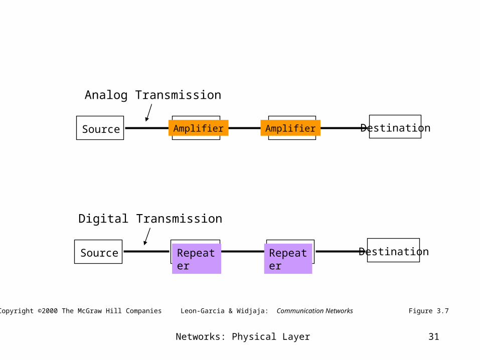
Figure 3.7Copyright ©2000 The McGraw Hill Companies Leon-Garcia & Widjaja: Communication Networks
Source Amplifier DestinationAmplifier
Analog Transmission
Source Repeater DestinationRepeater
Digital Transmission

Networks: Physical Layer 32
Attenuated & distorted signal +
noise
EqualizerRecovered signal
+residual noise
Amplifier
Amp.
Figure 3.8Copyright ©2000 The McGraw Hill Companies Leon-Garcia & Widjaja: Communication Networks
Analog Transmission
Networks: Physical Layer 33
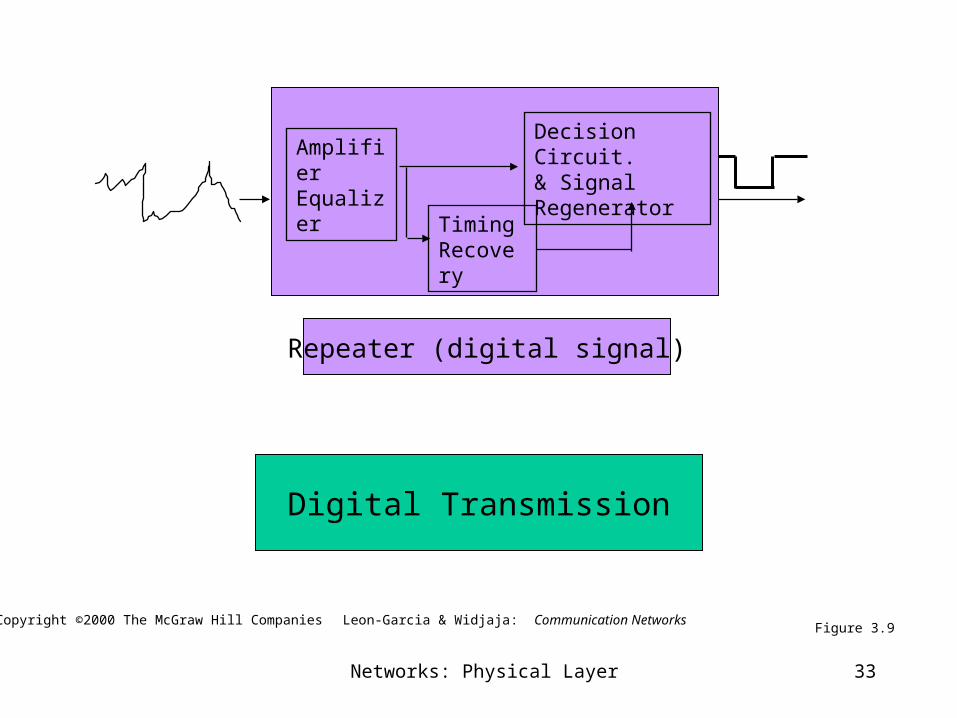
Figure 3.9
AmplifierEqualizer
TimingRecovery
Decision Circuit.& SignalRegenerator
Digital Transmission
Repeater (digital signal)
Leon-Garcia & Widjaja: Communication NetworksCopyright ©2000 The McGraw Hill Companies

Networks: Physical Layer 34
Digital versus Analog TransmissionsDCC 6th Ed. W.Stallings
Digital transmission advantages• Superior cost of digital technology
– Low cost LSI/VLSI technology
– Repeaters versus amplifiers costs
• Superior quality {Data integrity}– Longer distances over lines with lower error rates
• Capacity utilization– Economical to build high bandwidth links
– High degree of multiplexing easier with digital techniques• TDM (Time Division Multiplexing) is easier and cheaper than FDM
(Frequency Division Multiplexing)

Networks: Physical Layer 35
Digital versus Analog TransmissionsDCC 6th Ed. W.Stallings
Digital transmission advantages
• Security & Privacy
– Encryption techniques readily applied to digitized data
• Integration
– Can treat analog and digital data similarly
– Economies of scale from integrating voice, video and data
Analog transmission advantages
– Digital signaling not as versatile or practical (digital impossible for satellite and microwave systems)
– LAN star topology limits the severity of the noise and attenuation problems.


![[2] WCDMA Protocol Layer2 BMC](https://img.pdfslide.us/doc/110x75/5571fe3049795991699ad377/2-wcdma-protocol-layer2-bmc.jpg)