Embed Size (px)
Citation preview
MODULE INETWORKING CONCEPTS
OSI MODELEstablished in 1947, the International
Standards Organization (ISO) is a multinational body dedicated to worldwide agreement on international standards.
An ISO standard that covers all aspects of network communications is the Open Systems Interconnection (OSI) model.
It was first introduced in the late 1970s.
OSI MODELOpen System:
Set of protocols that allow only 2 different systems to communicate regardless of underlying architecture
OSI model is not a protocol,but a model for designing n/w architecture
Purpose is to show how to facilitate communication b/w different systems without requiring changes to the logic of the underlying h/w or s/w
OSI model is a layered framework for design of network systems
Consist of 7 layers
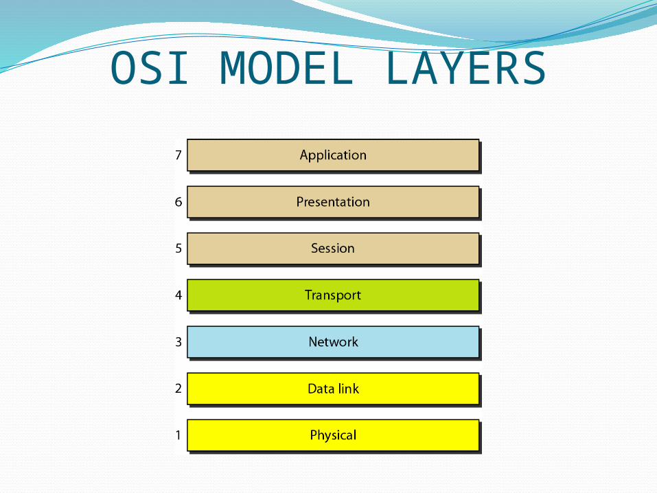
OSI MODEL LAYERS
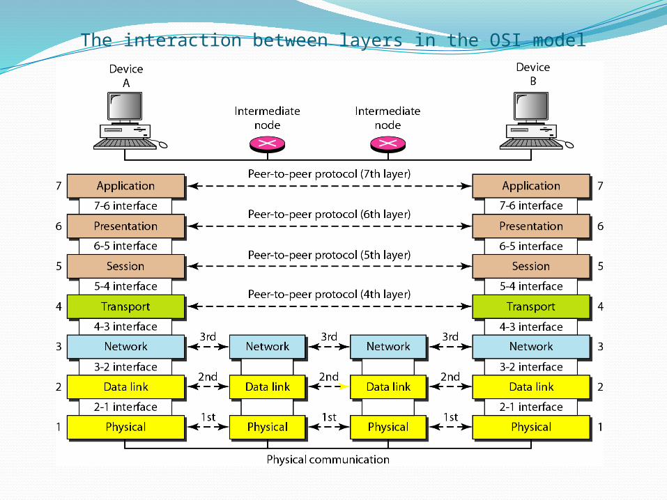
The interaction between layers in the OSI model
OSI MODELFig shows the layers involved when a
message is sent from A to BAs message travels from A to B it may pass
through many nodes and intermediate nodes usually involve only first 3 layers of OSI model
With a single machine each layer calls on services of layer just below it. Ie layer 3 provides services to layer 4 and uses services of layer2
OSI MODELBetween m/c layer x on one m/c
communicates with layer x on other m/c and that communication is governed by agreed rules called protocols
Processes on each machine that communicate at a given layer are called peer to peer processes
OSI MODELPeer to Peer Process
At physical layer communication is directIn fig device A sends stream of bits to device
B(through intermediate nodes)At higher layer communication must move down
through the layers through the layer on device A over to device B and then back up through layers
Each layer in sending device adds its own information to message it receives from the layer just above it and passes whole package to layer below it
OSI MODELPeer to Peer Process
At layer 1 the entire package is converted to a form that can be transmitted to the receiving device
At the receiving device msg is unwrapped layer by layer with each process receiving and removing the data meant for it
Eg. Layer 2 removes the data meant for it and then passes the rest to layer 3.Layer 3 removes the data meant for it and passes the rest to layer 4 and so on
OSI MODELInterface between layers
Defines the information and services a layer must provide for the layer above it
Organization of Layers7 layers belong to 3 subgroups
Layer 1,2,3 are n/w support layer deal with physical aspects of moving data from one device to other
Eg.electrical specifications,physical connector etc
OSI MODELOrganization of Layers
Layer 5,6,7.ie session presentation,application are user support layers and allow interoperability among unrelated s/w systems
Layer 4-Transport layerThis links two subgroups and ensures
that lower layer transmission is in a form that the upper layer can use
OSI MODELOrganization of LayersUpper OSI layers are commonly
implemented in s/w but lower layers are combination of h/w and s/w except physical which is mostly h/w
EXCHANGE USING OSI MODEL
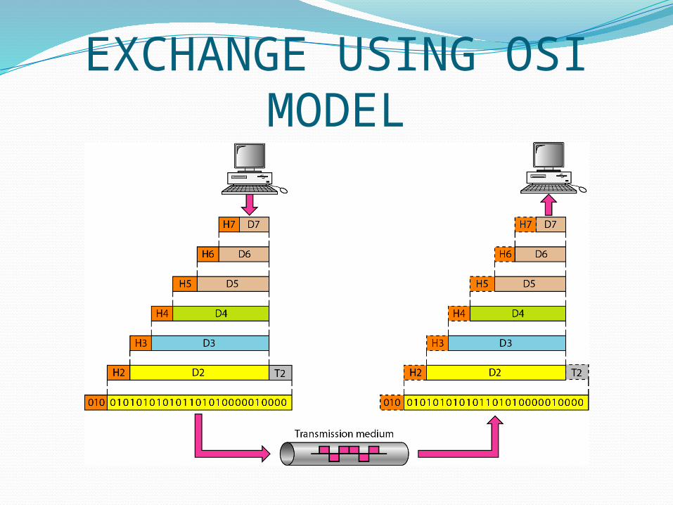
EXCHANGE USING OSI MODELD7 means data unit at layer 7The process starts at application layer and
moves from layer to layer in descending sequential order
At each layer header or trailer is added to data unit
Commonly trailer is added at layer 2After data unit passes through layer 1 and
it changed to some electromagnetic signal and is transported along a physical link
EXCHANGE USING OSI MODELOn destination side signal passes to layer
1 and is transformed back into digital formThe data units then move backup through
the OSI layersAs each block reaches next high layer,
header and trailer attached to it at the corresponding sending layer are removed actions appropriate to the layer are taken
EXCHANGE USING OSI MODELWhen it reaches layer 7 the message is
again in a form appropriate to the application and is made available to the recipient
EXCHANGE USING OSI MODELEncapsulationA packet (header+data) at level 7 is
encapsulated at level6ie data portion at level N-1 carries whole
packet from level N.This is encapsulation

EXCHANGE USING OSI MODELEncapsulationA packet (header+data) at level 7 is
encapsulated at level6ie data portion at level N-1 carries whole
packet from level N.This is encapsulation
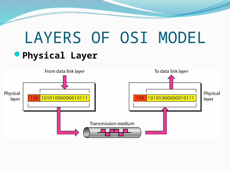
LAYERS OF OSI MODELPhysical Layer
LAYERS OF OSI MODELPhysical Layer
Deals with mechanical and electrical specifications of interface and transmission medium
Responsible for movements of individual bits from one node to next
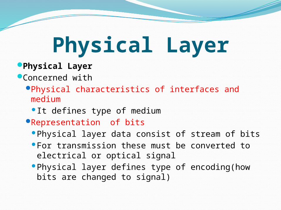
Physical LayerPhysical LayerConcerned with
Physical characteristics of interfaces and mediumIt defines type of medium
Representation of bitsPhysical layer data consist of stream of bitsFor transmission these must be converted to
electrical or optical signalPhysical layer defines type of encoding(how
bits are changed to signal)
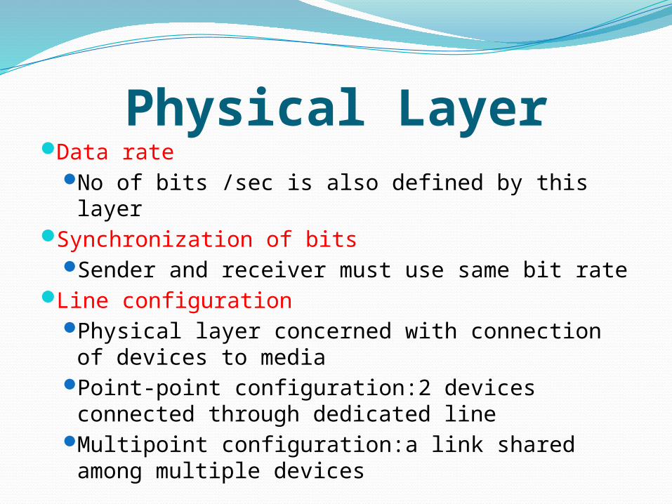
Physical LayerData rate
No of bits /sec is also defined by this layerSynchronization of bits
Sender and receiver must use same bit rateLine configuration
Physical layer concerned with connection of devices to media
Point-point configuration:2 devices connected through dedicated line
Multipoint configuration:a link shared among multiple devices
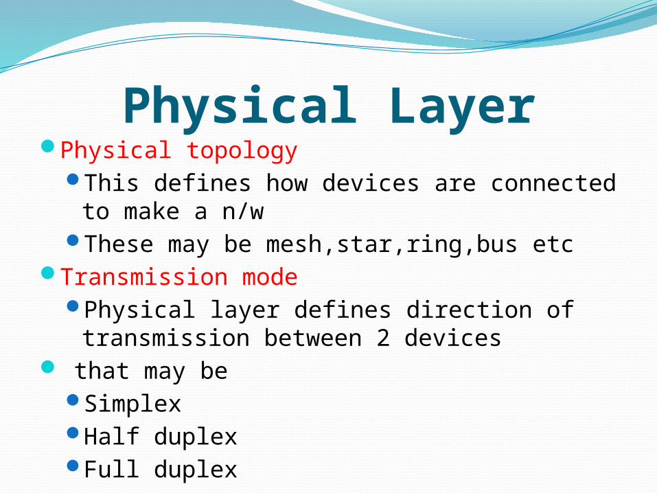
Physical LayerPhysical topology
This defines how devices are connected to make a n/w
These may be mesh,star,ring,bus etcTransmission mode
Physical layer defines direction of transmission between 2 devices
that may beSimplexHalf duplex Full duplex
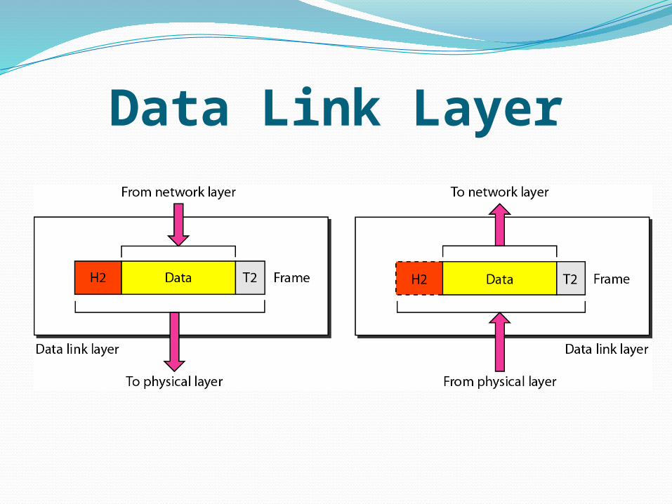
Data Link Layer
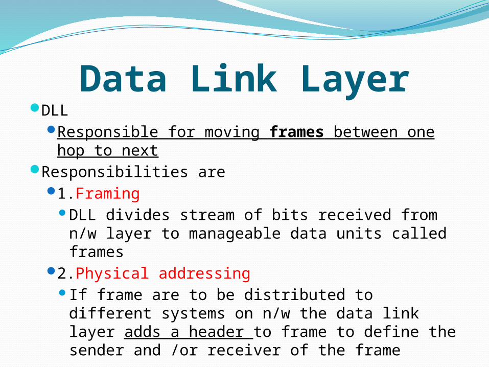
Data Link LayerDLL
Responsible for moving frames between one hop to next
Responsibilities are 1.Framing
DLL divides stream of bits received from n/w layer to manageable data units called frames
2.Physical addressingIf frame are to be distributed to different
systems on n/w the data link layer adds a header to frame to define the sender and /or receiver of the frame
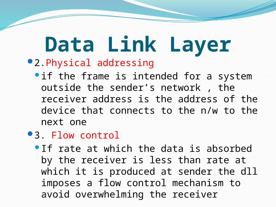
Data Link Layer2.Physical addressing
if the frame is intended for a system outside the sender’s network , the receiver address is the address of the device that connects to the n/w to the next one
3. Flow controlIf rate at which the data is absorbed by
the receiver is less than rate at which it is produced at sender the dll imposes a flow control mechanism to avoid overwhelming the receiver
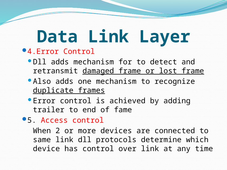
Data Link Layer4.Error Control
Dll adds mechanism for to detect and retransmit damaged frame or lost frame
Also adds one mechanism to recognize duplicate frames
Error control is achieved by adding trailer to end of fame
5. Access controlWhen 2 or more devices are connected to same link dll protocols determine which device has control over link at any time
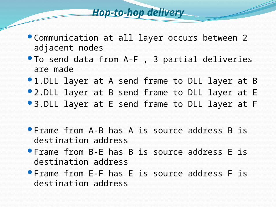
Hop-to-hop delivery
Hop-to-hop delivery
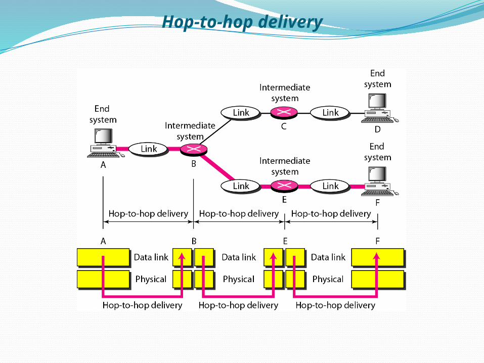
Communication at all layer occurs between 2 adjacent nodes
To send data from A-F , 3 partial deliveries are made
1.DLL layer at A send frame to DLL layer at B2.DLL layer at B send frame to DLL layer at E3.DLL layer at E send frame to DLL layer at F
Frame from A-B has A is source address B is destination address
Frame from B-E has B is source address E is destination address
Frame from E-F has E is source address F is destination address