Embed Size (px)
Citation preview

EC2352- COMPUTER
NETWORKS

UNIT I PHYSICAL LAYER
Data Communications – Networks - Networks
models – OSI model – Layers in OSI model – TCP /
IP protocol suite – Addressing – Guided and
Unguided Transmission media
Switching: Circuit switched networks – Data gram
Networks – Virtual circuit networks. Cable networks
for Data transmission: Dialup modems – DSL –
Cable TV – Cable TV for Data transfer.

TEXT BOOKS:
1. Behrouz A. Foruzan, “Data communication and
Networking”, Tata McGraw-Hill, 2006: Unit I-IV
2. Andrew S. Tannenbaum, “Computer Networks”,
Pearson Education, Fourth Edition, 2003: Unit V

CHAPTER 1
Data Communications Components
Data Representation
Data Flow
Networks Network criteria
Physical topology
Categories of Networks
Protocols Syntax
Semantics
Timing
DATA COMMUNICATIONS
Purpose of communication- to share information
Sharing Information can be local or remote.
The term telecommunication means communication
at a distance.
The word data refers to information presented in a
form agreed by the parties creating and using the
data
Data communications are the exchange of data
between two devices via some form of transmission
medium such as a wire cable.

COMPONENTS
DATA REPRESENTATION
Text - bit pattern (a sequence of 0’s and 1’s)
Numbers – bit pattern (number converted to binary)
Images – bit pattern
Audio – sound or music
Video – picture or movie

DATA FLOW

NETWORKS
A network is a set of devices (often referred to as
nodes) connected by communication links.
A node can be a computer, printer, or any other
device capable of sending and/or receiving data
generated by other nodes on the network.
A link can be a cable, air, optical fiber, or any
medium which can transport a signal carrying
information.

NETWORK CRITERIA
Performance
Depends on Network Elements
Reliability
Failure rate of network components
Security
Data protection against corruption/loss of data due to:
Errors
Malicious users

PHYSICAL STRUCTURES
Type of Connection
Point to Point - single transmitter and receiver
Multipoint - multiple recipients of single transmission

PHYSICAL STRUCTURES
How devices
are connected
to make a n/w.

MESH TOPOLOGY:
A physical topology in which every device has adedicated point to point link to every other device.
In mesh topology we need n(n-1)/2 links.
Advantages:
It eliminating traffic problems.
Fault identification is easy.
Mesh topology is robust.
Disadvantages:
It is expensive and difficult to install a mesh n/w.
Example:
Connection of telephone regional offices to everyother regional offices.
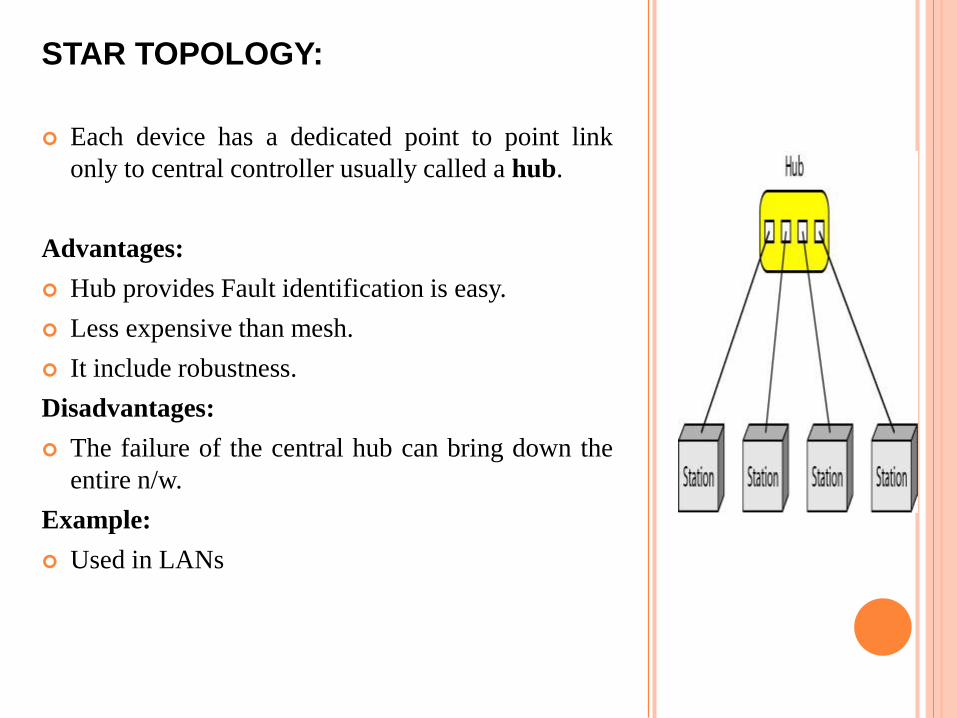
STAR TOPOLOGY:
Each device has a dedicated point to point link
only to central controller usually called a hub.
Advantages:
Hub provides Fault identification is easy.
Less expensive than mesh.
It include robustness.
Disadvantages:
The failure of the central hub can bring down the
entire n/w.
Example:
Used in LANs

BUS TOPOLOGY:
Bus topology is multipoint.
One long cable acts as a backbone to link all thedevices in a n/w.
Advantages:
Easy to add more workstations.
Inexpensive to install.
Bus topology works well for small n/ws
(2-10 devices)
Disadvantages:-
If the backbone breaks, the n/w goes down.
It is difficult to isolate where a problem may be.
Adding new devices may require modification orreplacement of the backbone.
Example:
Used in Ethernet LANs.
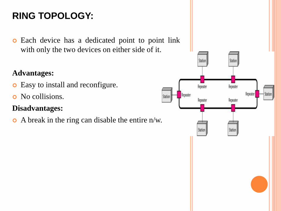
RING TOPOLOGY:
Each device has a dedicated point to point link
with only the two devices on either side of it.
Advantages:
Easy to install and reconfigure.
No collisions.
Disadvantages:
A break in the ring can disable the entire n/w.

CATEGORIES OF NETWORKS
Local Area Networks (LANs)
Limited to a few kilometers
Ex: single office, building or campus
Wide Area Networks (WANs)
Long distances
Provide connectivity over large areas ie,
country, continent
Metropolitan Area Networks (MANs)
Size b/w LAN and WAN
Inside city ie, cable tv n/w, telephone n/w

PROTOCOLS
A protocol is synonymous with rule. It consists of a set ofrules that govern data communications.
It determines what is communicated, how it iscommunicated and when it is communicated.
Elements of protocol:
Syntax
Structure or format of the data
Indicates how to read the bits - field
Semantics
Interprets the meaning of the bits
Knows which fields define what action
Timing
When data should be sent and what
Speed at which data should be sent or speed at which it is being received.

THE OSI MODEL
An ISO standard that covers all aspects of network
communications is the Open Systems
Interconnection (OSI) model.
An Open System is a set of protocols that allows
any two different systems to communicate
regardless of their underlying architecture.

SEVEN LAYERS OF THE OSI MODEL
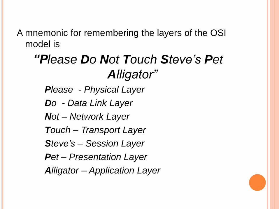
A mnemonic for remembering the layers of the OSI
model is
“Please Do Not Touch Steve’s Pet
Alligator”Please - Physical Layer
Do - Data Link Layer
Not – Network Layer
Touch – Transport Layer
Steve’s – Session Layer
Pet – Presentation Layer
Alligator – Application Layer

AN EXCHANGE USING THE OSI MODEL

PHYSICAL LAYER:
The physical layer is responsible for movements of individual bits from
one hop to the next.
Responsibilities:
Data rate : The number of bits sent each second.
Synchronization of bits : The sender and receiver clocks must
be synchronized.
Line configuration : Connection of device to the media.
Physical topology : How devices are connected to make a n/w.
Transmission mode : Direction of transmission b/w two
devices.

PHYSICAL LAYER

DATA LINK LAYER:
The Data link layer is responsible for moving frames from one hop to
the next.
Responsibilities:
Framing : Divides the stream of bits into manageable units
called frames.
Flow control : A technique to control the rate of flow of frames.
Error control : To handling errors in data transmission and to
detect and retransmit lost or damaged frames.
Access control : To determine which device has control over
the link at any given time.
Physical addressing : To handle the addressing problem
locally.

DATA LINK LAYER

HOP-TO-HOP DELIVERY

NETWORK LAYER:
The Network layer is responsible for the delivery of individual
packets from the source host to the destination host.
Responsibilities:
Logical addressing : The n/w layer adds a header to the
packet coming from upper layer that includes the logical
addresses of the sender and receiver.
Routing : When n/w are connected to create a large n/w, the
connecting devices route the packets to their final destination.

NETWORK LAYER

SOURCE-TO-DESTINATION DELIVERY

TRANSPORT LAYER:
The Transport layer is responsible for the delivery of a message from
one process to another.
Responsibilities:
Segmentation and reassembly : A message is divided into
transmittable segments and to reassemble the message
correctly upon arriving at the destination.
Connection control : It can be either connectionless or
connection oriented
Flow control : A technique to control the rate of flow of frames.
Error control : To handling errors in data transmission and to
detect and retransmit lost or damaged frames.

TRANSPORT LAYER

SESSION LAYER
Responsibilities:
Dialog Control :
It allows communication b/w
two processes to take place
in either half or full duplex
mode.
Synchronization :
It allows a process to add
checkpoints to a stream of
data.

PRESENTATION LAYER
Responsibilities:
Translation : Theprocesses in two systemsare usually exchanginginformation in the form ofcharacter strings, numbersand so on.
Encryption : Originalinformation to another form
Compression : Reducesthe number of bitscontained in the information.

APPLICATION LAYER
Services:
File Transfer, access and
management
Mail Services
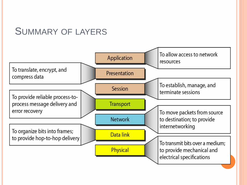
SUMMARY OF LAYERS

TCP/IP AND OSI MODEL
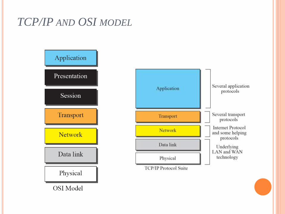
TCP/IP AND OSI MODEL

PHYSICAL & DATA LINK LAYERS:
TCP/IP does not define any specific protocol.
It support all the standard protocols.
NETWORK LAYER:
TCP/IP supports the Internetworking Protocol.
IP uses four supporting protocols
ARP, RARP, ICMP IGMP.
TRANSPORT LAYER:
It supports three protocols.
UDP, TCP ,SCTP.
APPLICATION LAYER:
Many protocols are defined at this layer.
SMTP, FTP, HTTP, DNS, SNMP, TELNET

ADDRESSES IN TCP/IP
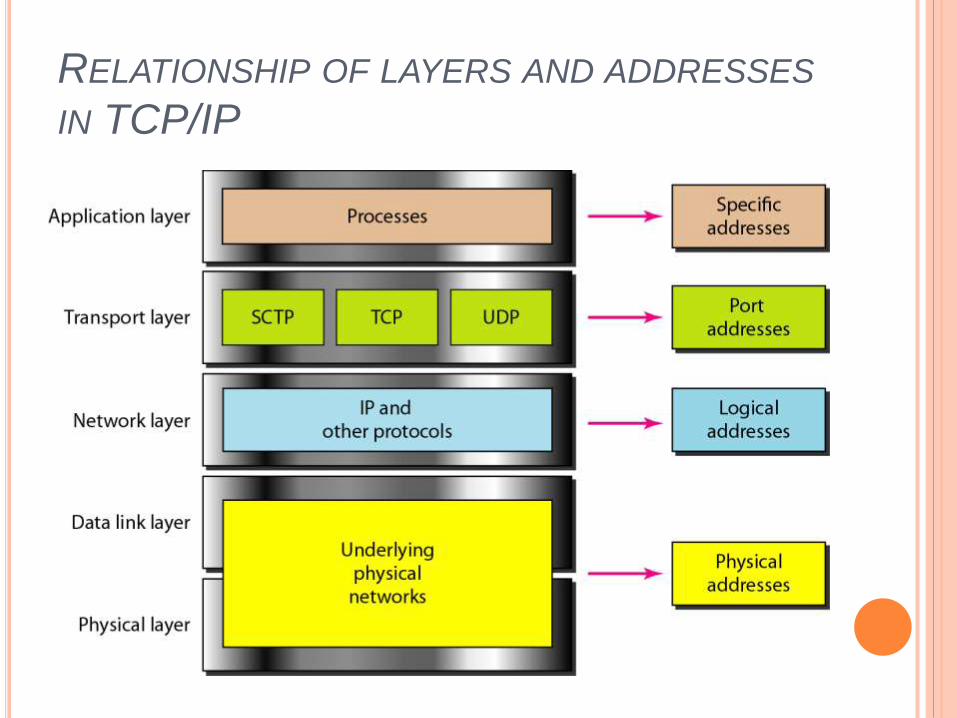
RELATIONSHIP OF LAYERS AND ADDRESSES
IN TCP/IP
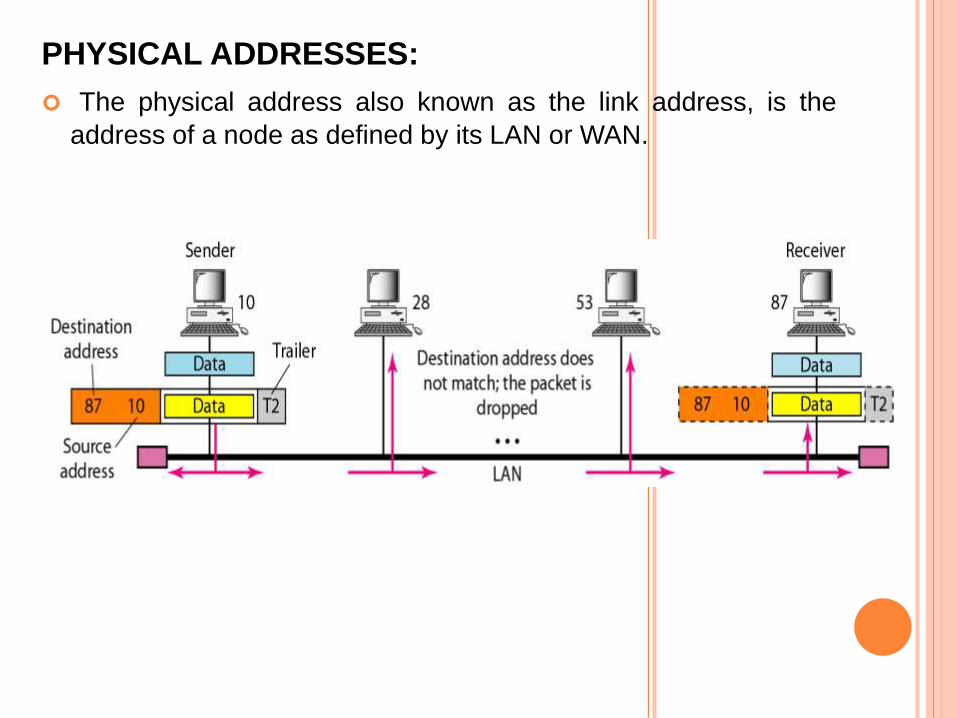
PHYSICAL ADDRESSES:
The physical address also known as the link address, is the
address of a node as defined by its LAN or WAN.

LOGICAL ADDRESSES:
Logical Addresses are necessary for universal communications.
A Universal addressing system is needed in which each host can
be identified uniquely.
A logical address in the internet is currently a 32-bit address.
The physical addresses will change from hop to hop, but the
logical addresses usually remain the same.
PORT ADDRESSES :
In TCP/IP architecture, the label assigned to a process is called
a port address.
A port address in TCP/IP is 16 bits in length.
SPECIFIC ADDRESSES:
User friendly addresses that are designed for that specific
address.
www.gmail.com