Embed Size (px)
Citation preview

Specification for Electrical Installations Page 1 of 73
4/2018
FOR THE LATEST AUTHORIZED VERSION PLEASE REFER TO THE COMPANY’S WEBSITE AT http://www.nationalgridus.com/electricalspecifications.
TABLE OF CONTENTS
1.0 DEFINITIONS ................................................................................................................. 4 Figure 1 – Cold Sequence Metering ..................................................................................................................... 4
2.0 SERVICES SUPPLIED FROM THE GENERAL NETWORK ......................................... 7
2.1 LOCATIONS ................................................................................................................................................. 7
2.2 GENERAL NETWORK SERVICES ............................................................................................................. 7 Figure 2 – Typical General Network Service Layout ............................................................................................. 7 GENERAL NETWORK SERVICE SIZES ............................................................................................................. 8
2.3 SINGLE PHASE, TWO WIRE OR THREE WIRE ........................................................................................ 8 Figure 3 – 100 to 200 amperes Single Phase Equipment Example Layout ......................................................... 8 Figure 4 – Single Phase Junction Enclosure Example Layout with conductors ................................................... 9
2.4 200 AMPERES, THREE PHASE, FOUR WIRE ........................................................................................ 11 Figure 5 – 200 amperes Three Phase Equipment Example Layout ................................................................... 11 Figure 6 – 200 amperes Three Phase Junction Enclosure Example Layout with conductors ............................ 12
2.5 400 AMPERES, THREE PHASE, FOUR WIRE ........................................................................................ 14 Figure 7 – 400 amperes Three Phase Equipment Example Layout ................................................................... 14 Figure 8 – 400 amperes Three Phase Junction Enclosure Example Layout with conductors ............................ 15
2.6 800 AMPERES, THREE PHASE, FOUR WIRE ........................................................................................ 17 Figure 9 – 800 amperes Three Phase Equipment Example Layout ................................................................... 17 Figure 10 – 800 amperes Three Phase Junction Enclosure Example Layout with conductors .......................... 18
2.7 1000 TO 1600 AMPERES, THREE PHASE, FOUR WIRE ....................................................................... 20 2.7.1 Figure 11 – 1000 to 1600 amperes Three Phase Equipment Example Layout ..................................... 20 Figure 12 – 1000 to 1600 amperes Limiter Enclosure (Top Entry from Wall) ..................................................... 22 Figure 13 – 1000 to 1600 amperes Limiter Enclosure (Bottom Entry from Wall) ............................................... 23 Figure 14 – 1000 to 1600 amperes Limiter Enclosure (Bottom Entry from Floor) .............................................. 24
3.0 NETWORK SERVICES FROM CUSTOMER-OWNED TRANSFORMER VAULTS .... 26
3.1 GENERAL .................................................................................................................................................. 26 Figure 15 – Customer-Owned Transformer Vaults with Interconnection to General Network ............................ 26 Figure 16 – Spot Network Customer-Owned Transformer Vaults ...................................................................... 27 3.1.1 Service Details for Network Services from Customer-Owned Vaults .................................................... 27 3.1.2 Project Details to be Furnished by the Customer to the Company ........................................................ 27 3.1.3 Project Details to be Furnished by the Company to the Customer ........................................................ 28
3.2 LOCATION AND ARRANGEMENT OF SERVICE FACILITIES ............................................................... 28 3.2.1 Location of Service Conductors ............................................................................................................. 28 3.2.2 Location of Network Transformers ......................................................................................................... 28
3.3 REQUIREMENTS, APPROVALS, AND INSPECTIONS ........................................................................... 28 3.3.1 Requirements ......................................................................................................................................... 28 3.3.2 Codes, Standards and Wiring Adequacy ............................................................................................... 28 3.3.3 National Grid Approval ........................................................................................................................... 28 3.3.4 Local Authority Approval ........................................................................................................................ 29

Specification for Electrical Installations Page 2 of 73
4/2018
FOR THE LATEST AUTHORIZED VERSION PLEASE REFER TO THE COMPANY’S WEBSITE AT http://www.nationalgridus.com/electricalspecifications.
3.4 VAULT EASEMENT AGREEMENT ........................................................................................................... 29
3.5 DIVISION OF RESPONSIBILITIES ........................................................................................................... 29
3.6 SERVICE CAPABILITY ............................................................................................................................. 30 Table 1 – Service Capability ............................................................................................................................... 30
3.7 VAULT DESIGN, LOCATION, AND ACCESS .......................................................................................... 30 3.7.1 All Vaults ................................................................................................................................................ 30 3.7.2 Building Vaults and Free-Standing Above-Grade Vaults ....................................................................... 31 Table 2 – Standard Arrangements - Building Vaults and Free-Standing Above-Grade Vaults .......................... 32 3.7.3 Below-Grade Vaults Located Outdoors.................................................................................................. 32 Table 3 – Minimum Access Requirements for non-precast Below-Grade Vaults ............................................... 33
3.8 CONSTRUCTION ....................................................................................................................................... 33 3.8.1 Company Requirements, Specifications, and Inspection ....................................................................... 33 3.8.2 Foreign Structures .................................................................................................................................. 33 3.8.3 Code Requirements ............................................................................................................................... 33 3.8.4 Walls, Roof, and Floor ............................................................................................................................ 34 3.8.5 Floor, Ceiling, and Wall Loading (Weights) ............................................................................................ 35 Table 4 – Network Unit Weights .......................................................................................................................... 35 3.8.6 Doors (Building Vaults and Free-Standing Above-Grade Vaults) .......................................................... 35 3.8.7 Ladders (Below-Grade Vaults) ............................................................................................................... 36 Figure 41 – OSHA Figure D-11 – Pitch of Fixed Ladders ................................................................................... 37 Figure 42 – OSHA Figure D-2 ............................................................................................................................. 38 Figure 43 – Ladder Extension ............................................................................................................................. 39 3.8.8 Lighting and Convenience Outlets ......................................................................................................... 39 3.8.9 Ventilation ............................................................................................................................................... 40 Table 5 – Required Vault Heat Dissipation ......................................................................................................... 41 3.8.10 Conduit and Equipment Foundations ................................................................................................ 41 3.8.11 Construction Inspection ..................................................................................................................... 41 3.8.12 Fluid Volume and Liquid Curb (Building Vaults and Free-Standing Above-Grade Vaults) ............... 42 Table 6 - Fluid Volume ........................................................................................................................................ 42 3.8.13 Audible Sound Levels ........................................................................................................................ 42
3.9 FIRE SUPPRESSION SYSTEMS .............................................................................................................. 42 3.9.1 Design and Installation ........................................................................................................................... 42 3.9.2 Construction ........................................................................................................................................... 43 3.9.3 Variances ............................................................................................................................................... 43 3.9.4 Easement Language .............................................................................................................................. 43
3.10 ELECTRICAL ............................................................................................................................................. 43 3.10.1 Grounding .......................................................................................................................................... 43 Figure 44 – Vault Grounding Loop ...................................................................................................................... 44 3.10.2 Interrupting ......................................................................................................................................... 45 Table 7 - Spot Network Service - Available Short Circuit Current....................................................................... 45 3.10.3 Secondary Conductors and Construction .......................................................................................... 45 3.10.4 Protective Device Coordination ......................................................................................................... 46 3.10.5 Ground Fault Protection System - 480Y/277 volt Network Service ................................................... 46 3.10.6 Arc Flash Mitigation - 480Y/277 volt Network Service ....................................................................... 47 3.10.7 Fire Pump Service ............................................................................................................................. 47
3.11 VAULT MAINTENANCE ............................................................................................................................ 47 3.11.1 Qualified Personnel ............................................................................................................................ 47 3.11.2 Customer Access to Company-Controlled Spaces within Customer-Owned Facilities ..................... 47
3.12 APPENDICES ............................................................................................................................................ 49

Specification for Electrical Installations Page 3 of 73
4/2018
FOR THE LATEST AUTHORIZED VERSION PLEASE REFER TO THE COMPANY’S WEBSITE AT http://www.nationalgridus.com/electricalspecifications.
Figure 17 – Building & Free-Standing Vault Standard Arrangements, 2 – 1000 kVA, 15 kV ............................. 49 Figure 18 – Building & Free-Standing Vault Standard Arrangements, 3 – 1000 kVA, 15 kV ............................. 49 Figure 19 – Building & Free-Standing Vault Standard Arrangements, 4 – 1000 kVA, 15 kV ............................. 50 Figure 20 – Building & Free-Standing Vault Standard Arrangements, 2 – 1500 kVA, 15 kV ............................. 50 Figure 21 – Building & Free-Standing Vault Standard Arrangements, 3 – 1500 kVA, 15 kV ............................. 51 Figure 22 – Building & Free-Standing Vault Standard Arrangements, 4 – 1500 kVA, 15 kV ............................. 51 Figure 23 – Building & Free-Standing Vault Standard Arrangements, 2 – 2000 kVA, 15 kV ............................. 52 Figure 24 – Building & Free-Standing Vault Standard Arrangements, 3 – 2000 kVA, 15 kV ............................. 52 Figure 25 – Building & Free-Standing Vault Standard Arrangements, 4 – 2000 kVA, 15 kV ............................. 53 Figure 26 – Building & Free-Standing Vault Standard Arrangements, 2 – 2500 kVA, 15 kV ............................. 53 Figure 27 – Building & Free-Standing Vault Standard Arrangements, 3 – 2500 kVA, 15 kV ............................. 54 Figure 28 – Building & Free-Standing Vault Standard Arrangements, 4 – 2500 kVA, 15 kV ............................. 54 Figure 29 – Building & Free-Standing Vault Standard Arrangements, 2 – 1000 kVA, 23 kV ............................. 55 Figure 30 – Building & Free-Standing Vault Standard Arrangements, 3 – 1000 kVA, 23 kV ............................. 55 Figure 31 – Building & Free-Standing Vault Standard Arrangements, 4 – 1000 kVA, 23 kV ............................. 56 Figure 32 – Building & Free-Standing Vault Standard Arrangements, 2 – 1500 kVA, 23 kV ............................. 56 Figure 33 – Building & Free-Standing Vault Standard Arrangements, 3 – 1500 kVA, 23 kV ............................. 57 Figure 34 – Building & Free-Standing Vault Standard Arrangements, 4 – 1500 kVA, 23 kV ............................. 57 Figure 35 – Building & Free-Standing Vault Standard Arrangements, 2 – 2000 kVA, 23 kV ............................. 58 Figure 36 – Building & Free-Standing Vault Standard Arrangements, 3 – 2000 kVA, 23 kV ............................. 58 Figure 37 – Building & Free-Standing Vault Standard Arrangements, 4 – 2000 kVA, 23 kV ............................. 59 Figure 38 – Building & Free-Standing Vault Standard Arrangements, 2 – 2500 kVA, 23 kV ............................. 59 Figure 39 – Building & Free-Standing Vault Standard Arrangements, 3 – 2500 kVA, 23 kV ............................. 60 Figure 40 – Building & Free-Standing Vault Standard Arrangements, 4 – 2500 kVA, 23 kV ............................. 60 Figure 41 – Building & Free-Standing Vault Standard Arrangements, 2 – 1500 kVA, 34.5 kV .......................... 61 Figure 42 – Building & Free-Standing Vault Standard Arrangements, 3 – 1500 kVA, 34.5 kV .......................... 61 Figure 43 – Building & Free-Standing Vault Standard Arrangements, 4 – 1500 kVA, 34.5 kV .......................... 62 Figure 44 – Building & Free-Standing Vault Standard Arrangements, 2 – 2000 kVA, 34.5 kV .......................... 62 Figure 45 – Building & Free-Standing Vault Standard Arrangements, 3 – 2000 kVA, 34.5 kV .......................... 63 Figure 46 – Building & Free-Standing Vault Standard Arrangements, 4 – 2000 kVA, 34.5 kV .......................... 63 Figure 47 – Building & Free-Standing Vault Standard Arrangements, 2 – 2500 kVA, 34.5 kV .......................... 64 Figure 48 – Building & Free-Standing Vault Standard Arrangements, 3 – 2500 kVA, 34.5 kV .......................... 64 Figure 49 – Building & Free-Standing Vault Standard Arrangements, 4 – 2500 kVA, 34.5 kV .......................... 65 Figure 50 – Below-Grade Vault Located Outdoors Standard Layout ................................................................. 65 Figure 51 – 6” Concrete Wall Minimum Standards ............................................................................................. 66 Figure 52 – 8” Concrete Wall Minimum Standards ............................................................................................. 66 Figure 53 – CMU Wall Minimum Standards Plan View ....................................................................................... 67 Figure 54 – CMU Wall Minimum Standards Isometric View ............................................................................... 67 Figure 55 – Concrete Floor Minimum Standards ................................................................................................ 68 Figure 56 – Below Grade Vault Loading (Detail Common to NESC 2012 and AASHTO 2012) ......................... 69 Figure 57 – Ground Fault Protection Interconnection Example .......................................................................... 71 Figure 58 – Ground Fault Protection Control System Example Sheet 1 ............................................................ 72 Figure 59 – Ground Fault Protection Control System Example Sheet 2 ............................................................ 73

Specification for Electrical Installations Page 4 of 73
4/2018
FOR THE LATEST AUTHORIZED VERSION PLEASE REFER TO THE COMPANY’S WEBSITE AT http://www.nationalgridus.com/electricalspecifications.
1.0 DEFINITIONS Applicant: Any entity (individual, firm, partnership, corporation, association, municipality, or governmental body) requesting a new service from the Company for their own use and not for resale or delivery to others. Note: The Company must be consulted for specific Applicant rules as they apply in the Company’s applicable tariff.
Authority Having Jurisdiction (AHJ): Governmental bodies or their Agent exercising legal jurisdiction over applicable codes.
Building: A structure which stands alone or which is cut off from adjoining structures by approved fire walls with all openings therein protected by approved fire doors.
Cable Limiter1: An enclosed fuse for disconnecting a faulted cable from a low-voltage network distribution system and for protecting the unfaulted portion of that cable against serious thermal damage. Note: A cable limiter is also referred to as a network limiter or a limiter.
Clearance: Required separation mandated by codes or the Company.
Cold Sequence metering: Metering equipment located on the Customer’s side of the service equipment. Refer to Figure 1.
Figure 1 – Cold Sequence Metering
Company: The electric utility companies doing business as National Grid to which these requirements apply are:
Massachusetts Electric Company The Narragansett Electric Company Niagara Mohawk Power Corporation
Company Approval: Acceptance for the minimum requirements of National Grid exclusive of the Customer’s obligation of complying with all applicable codes, statutes, rules or regulations.
Conduit: A cylindrical wire-way for the purpose of carrying and protecting electric cables.
Customer: An existing user of recurring electric service. A contractor or developer performing work on behalf of a Customer is considered an agent of the Customer.
1 IEEE Std C57.12.44-2005, pages 2-3

Specification for Electrical Installations Page 5 of 73
4/2018
FOR THE LATEST AUTHORIZED VERSION PLEASE REFER TO THE COMPANY’S WEBSITE AT http://www.nationalgridus.com/electricalspecifications.
Design Professional: A Professional Engineer (PE) licensed to practice in the state where service is being installed and who is directly retained by the Customer for that purpose. If the state licensed PE is representing a multi-member design firm, the firm shall have state certification to practice professional engineering and a copy of such license must be provided to the Company upon request. Any Company requested design professional certification proof must be submitted to the Company in writing upon initial design submission.
Distribution Line: A distribution line is an electric line, either overhead or underground, including the necessary and ancillary accessories to distribute electric energy, which may provide service to more than one customer. A distribution line may be located (1) in a street, highway, alley, or (2) on private right-of-way when used or useful to supply two or more customers at separate premises.
Electric Service: Maintenance by the Company of the appropriate voltage and frequency at the point of delivery shall constitute the delivery of electric service to the Customer.
Electrical Inspector: Inspectors external to the Company who are approved by the municipality in which they are working and recognized by the Company. Electrical Inspectors are responsible for ensuring that the installation complies with all applicable codes and Company requirements, service equipment, material, installations, and/or procedures.
Emergency: An unplanned natural or accidental event that affects existing electric service.
Emergency Power System: A system legally required and classed as emergency by codes or any governmental agency having jurisdiction that automatically provides an independent reserve source of electricity, upon failure or outage of the normal power source, to elements of a power system essential to the safety of human life.
Exclusive Control: Generally covers installation, ownership, restricted access, operation, and maintenance by qualified and authorized persons.
Fire Wall: A wall separating buildings or subdividing a building to prevent the spread of fire and having a fire resistance rating and structural stability as determined and approved in writing by the AHJ.
General Network2: A secondary network system with geographically separated network units and the network-side terminals of the network protectors interconnected by low-voltage cables that span the distance between sites. The low-voltage cable circuits of the general networks are typically highly meshed and supplied by numerous network units. Note: A general network is also referred to as a street network, or an area network.
Multiple Residential Occupancy Building: A structure, including row houses, enclosed within exterior walls or fire walls, which is built, erected and framed of component structural parts and is designed to contain four or more individual dwelling units for permanent residential occupancy.
Non-Residential Service: All service types other than residential.
Primary: The Company’s distribution systems typically operating over 600 volts.
2 National Renewable Energy Laboratory Technical Report NREL/TP-560-38079, July 2005, pages 5-6

Specification for Electrical Installations Page 6 of 73
4/2018
FOR THE LATEST AUTHORIZED VERSION PLEASE REFER TO THE COMPANY’S WEBSITE AT http://www.nationalgridus.com/electricalspecifications.
Residential Service: Service to one or more dwelling unit(s) providing complete and independent living facilities for one or more persons and which include permanent provisions for sleeping, cooking, and sanitation.
Secondary: The Company’s distribution systems typically operating at 600 volts or below.
Service: The conductors and equipment for delivering energy from the Company's distribution line to the wiring system of the Customer served.
Secondary Collector Bus: Conductors utilized to parallel transformers or network units, also known as Transformer Paralleling Bus.
Service entrance: That part of the Customer’s wiring from the point of attachment or termination of the service lateral or service line to and including the service equipment.
Service equipment: The Customer’s necessary disconnecting and protective equipment intended to constitute the main control and cutoff of the supply from the service point. This consists of a circuit breaker(s) or switch(es) and fuse(s) and their accessories connected to the load end of service conductors. The service overcurrent device shall be an integral part of the service disconnecting means or shall be located immediately adjacent thereto.
Spot Network3: A small network, usually at one location, consisting of two or more primary feeders, with network units and one or more load service connections.
3 IEEE Std C57.12.44-2005, pages 2-3

Specification for Electrical Installations Page 7 of 73
4/2018
FOR THE LATEST AUTHORIZED VERSION PLEASE REFER TO THE COMPANY’S WEBSITE AT http://www.nationalgridus.com/electricalspecifications.
2.0 SERVICES SUPPLIED FROM THE GENERAL NETWORK
2.1 LOCATIONS In the urban centers of the following Municipalities, customers may be served from one of the Company’s Low Voltage Alternating Current (LVAC) Network systems.
New York: Massachusetts: Rhode Island: Albany Brockton Pawtucket Buffalo Lynn Providence Cortland Worcester Glens Falls Niagara Falls Schenectady Syracuse Troy Utica Watertown
2.2 GENERAL NETWORK SERVICES Service voltages of 208Y/120 volts can be served from the general network subject to capacity limitations that are dictated by each particular LVAC system and geographic locations. Company owned conductors are connected from the 208Y/120 volt source in the public right-of-way and terminated to customer owned conductors within a customer owned enclosure (Refer to Figure 2). Service sizes larger than area system limitations or voltages of 480Y/277 volts will require supply from transformers in customer owned vaults.
Not all service sizes can be supplied from network facilities in all areas.
Customers shall consult the Company in the early stages of a project with load information, service requirements, and applicable site plans.
Figure 2 – Typical General Network Service Layout

Specification for Electrical Installations Page 8 of 73
4/2018
FOR THE LATEST AUTHORIZED VERSION PLEASE REFER TO THE COMPANY’S WEBSITE AT http://www.nationalgridus.com/electricalspecifications.
GENERAL NETWORK SERVICE SIZES
The following diagrams are intended as an illustrative reference for service requirements. Actual equipment layouts may differ.
2.3 SINGLE PHASE, TWO WIRE OR THREE WIRE Massachusetts & Rhode Island, 100 amperes maximum
New York, 200 amperes maximum
Figure 3 – 100 to 200 amperes Single Phase Equipment Example Layout
1. Junction / Termination Enclosure and Conductors:
a. Customer installed and owned in a location mutually agreed upon by the Company and customer
b. Minimum dimensions: 10 in (252 mm) x 10 in (252 mm) x 8 in (203 mm)
c. Shall be located at the closest possible point to conduit entrance into the building and be accessible by company personal for cable pulling and splicing
d. The floor area in front of the junction box shall provide minimally 8 ft of working clearance and be suitable for the installation of anchor inserts.
e. Shall have provisions for locking and sealing with the Company’s standard padlock
f. Junction boxes installed outdoors shall be listed as weatherproof
g. Shall meet applicable NEC requirements and listings
h. Company conductors shall be spliced to customer owned conductors within this enclosure. Company conductor size shall be XHHW type, #2 soft drawn copper (100 ampere) or 4/0 soft drawn copper (200 ampere).

Specification for Electrical Installations Page 9 of 73
4/2018
FOR THE LATEST AUTHORIZED VERSION PLEASE REFER TO THE COMPANY’S WEBSITE AT http://www.nationalgridus.com/electricalspecifications.
i. The Customer shall install the junction box oriented, and with conduits entering the box, such that parallel connections may be made between Company and customer cables. Orientation of the junction box and conduits can be adjusted as needed to accommodate actual installation; however the relative locations of the conduits that house the Company and customer cables shall be as shown in Figure 4.
j. Customer owned conductors shall be XHHW type, soft drawn copper.
k. Connectors will be provided by the Company, and connections in the junction box will be made by the Company.
Figure 4 – Single Phase Junction Enclosure Example Layout with conductors
2. Service Conduits:
a. The junction between customer owned and installed conduits and Company owned and installed conduits shall be at a mutually agreed upon location
b. Shall be minimally 4 inch nominal
c. Number of service conduits and spare conduits shall be determined by the Company
d. Customer shall be responsible for all building foundation penetrations
e. All conduits containing company owned conductors that penetrate the building foundation shall be rigid galvanized steel
f. All conduits containing company owned conductors installed outside of the building foundation shall be rigid galvanized steel or concrete-encased PVC
g. All exposed conduits containing company owned conductors and/or conduits before (up-stream of) metering equipment shall be rigid galvanized steel
h. Conduit sweep radii shall be minimally 36 inches
Specification for Electrical Installations Page 10 of 73
4/2018
FOR THE LATEST AUTHORIZED VERSION PLEASE REFER TO THE COMPANY’S WEBSITE AT http://www.nationalgridus.com/electricalspecifications.
3. Conductor wire-ways / troughs before metering:
a. Customer installed and owned
b. Shall not contain metered or load side conductors
c. Shall be Rigid Galvanized steel, Lockable wire-way / troughs, or incorporated into a securable enclosure
d. Shall be sized in accordance with NEC requirements
4. Service Equipment / Main Disconnect:
a. Customer installed and owned
b. Shall contain only a Single Disconnecting Device before Metering Equipment
c. Shall have a minimum short circuit withstand rating of 100,000 amperes RMS symmetrical
d. Main Over-current Protection shall meet required withstand rating and applicable NEC requirements and listings
5. Metering Equipment:
a. Shall be Cold Sequenced
b. Shall be located as close as possible to the Service Equipment / Main Disconnect in one central location
c. No unmetered conductors shall be installed beyond the central metering location
d. Refer to ESB 750 for appropriate specifications

Specification for Electrical Installations Page 11 of 73
4/2018
FOR THE LATEST AUTHORIZED VERSION PLEASE REFER TO THE COMPANY’S WEBSITE AT http://www.nationalgridus.com/electricalspecifications.
2.4 200 AMPERES, THREE PHASE, FOUR WIRE
Figure 5 – 200 amperes Three Phase Equipment Example Layout
1. Junction / Termination Enclosure and Conductors:
a. Customer installed and owned in a location mutually agreed upon by the Company and customer
b. Minimum dimensions: 24 in (610 mm) x 24 in (610 mm) x 12 in (305 mm)
c. Shall be located at the closest possible point to conduit entrance into the building and be accessible by company personal for cable pulling and splicing
d. The floor area in front of the junction box shall provide minimally 8 ft of working clearance and be suitable for the installation of anchor inserts.
e. Shall have provisions for locking and sealing with the Company’s standard padlock
f. Junction boxes installed outdoors shall be listed as weatherproof
g. Shall meet applicable NEC requirements and listings
h. Company conductors shall be spliced to customer owned conductors within this enclosure. Company conductor size shall be XHHW type, 4/0 soft drawn copper.
i. The Customer shall install the junction box oriented, and with conduits entering the box, such that parallel connections may be made between Company and customer cables. Orientation of the junction box and conduits can be adjusted as needed to accommodate actual installation; however the relative locations of the conduits that house the Company and customer cables shall be as shown in Figure 6.
j. Customer owned conductors shall be XHHW type, soft drawn copper.
Specification for Electrical Installations Page 12 of 73
4/2018
FOR THE LATEST AUTHORIZED VERSION PLEASE REFER TO THE COMPANY’S WEBSITE AT http://www.nationalgridus.com/electricalspecifications.
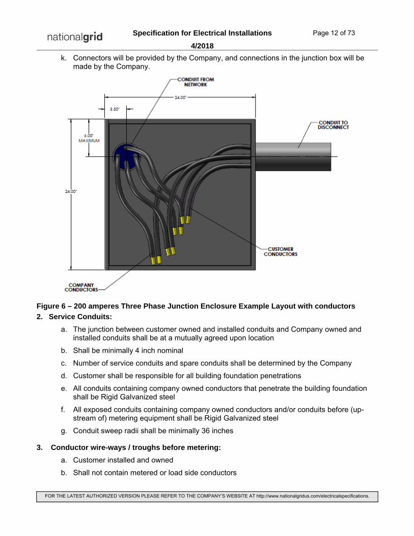
k. Connectors will be provided by the Company, and connections in the junction box will be made by the Company.
Figure 6 – 200 amperes Three Phase Junction Enclosure Example Layout with conductors
2. Service Conduits:
a. The junction between customer owned and installed conduits and Company owned and installed conduits shall be at a mutually agreed upon location
b. Shall be minimally 4 inch nominal
c. Number of service conduits and spare conduits shall be determined by the Company
d. Customer shall be responsible for all building foundation penetrations
e. All conduits containing company owned conductors that penetrate the building foundation shall be Rigid Galvanized steel
f. All exposed conduits containing company owned conductors and/or conduits before (up-stream of) metering equipment shall be Rigid Galvanized steel
g. Conduit sweep radii shall be minimally 36 inches
3. Conductor wire-ways / troughs before metering:
a. Customer installed and owned
b. Shall not contain metered or load side conductors
Specification for Electrical Installations Page 13 of 73
4/2018
FOR THE LATEST AUTHORIZED VERSION PLEASE REFER TO THE COMPANY’S WEBSITE AT http://www.nationalgridus.com/electricalspecifications.
c. Shall be Rigid Galvanized steel, Lockable wire-way / troughs, or incorporated into a securable enclosure
d. Shall be sized in accordance with NEC requirements
4. Service Equipment / Main Disconnect:
a. Customer installed and owned
b. Shall contain only a Single Disconnecting Device before Metering Equipment
c. Shall have a minimum short circuit withstand rating of 100,000 amperes RMS symmetrical
d. Main Over-current Protection shall meet required withstand rating and applicable NEC requirements and listings
5. Metering Equipment:
a. Shall be Cold Sequenced
b. Shall be located as close as possible to the Service Equipment / Main Disconnect in one central location
c. No unmetered conductors shall be installed beyond the central metering location
d. Refer to ESB 750 for appropriate specifications

Specification for Electrical Installations Page 14 of 73
4/2018
FOR THE LATEST AUTHORIZED VERSION PLEASE REFER TO THE COMPANY’S WEBSITE AT http://www.nationalgridus.com/electricalspecifications.
2.5 400 AMPERES, THREE PHASE, FOUR WIRE
Figure 7 – 400 amperes Three Phase Equipment Example Layout
1. Junction / Termination Enclosure and Conductors:
a. Customer installed and owned in a location mutually agreed upon by the Company and customer
b. Minimum dimensions: 36 in (915 mm) height x 24 in (610 mm) width x 12 in (305 mm) deep
c. Shall be located at the closest possible point to conduit entrance into the building and be accessible by company personal for cable pulling and splicing
d. The floor area in front of the junction box shall provide minimally 8 ft of working clearance and be suitable for the installation of anchor inserts.
e. Shall have provisions for locking and sealing with the Company’s standard padlock
f. Junction boxes installed outdoors shall be listed as weatherproof
g. Shall meet applicable NEC requirements and listings
h. Company conductors shall be spliced to customer owned conductors within this enclosure. Company conductor size shall be XHHW type, 500 kcmil soft drawn copper.
i. The Customer shall install the junction box oriented, and with conduits entering the box, such that parallel connections may be made between Company and customer cables. Orientation of the junction box and conduits can be adjusted as needed to accommodate actual installation; however the relative locations of the conduits that house the Company and customer cables shall be as shown in Figure 8.
j. Customer owned conductors shall be XHHW type, soft drawn copper.

Specification for Electrical Installations Page 15 of 73
4/2018
FOR THE LATEST AUTHORIZED VERSION PLEASE REFER TO THE COMPANY’S WEBSITE AT http://www.nationalgridus.com/electricalspecifications.
k. Connectors will be provided by the Company up to a maximum conductor size of 500 kcmil, and connections in the junction box will be made by the Company. For installations with customer owned conductors larger than 500 kcmil, the customer shall provide the required connector which shall be bronze vise-type Electric Motion Company catalog number EM23— or an approved equal.
Figure 8 – 400 amperes Three Phase Junction Enclosure Example Layout with conductors
2. Service Conduits:
a. The junction between customer owned and installed conduits and Company owned and installed conduits shall be at a mutually agreed upon location
b. Shall be minimally 4 inch nominal
c. Number of service conduits and spare conduits shall be determined by the Company
d. Customer shall be responsible for all building foundation penetrations
e. All conduits containing company owned conductors that penetrate the building foundation shall be Rigid Galvanized steel
f. All exposed conduits containing company owned conductors and/or conduits before (up-stream of) metering equipment shall be Rigid Galvanized steel
g. Conduit sweep radii shall be minimally 36 inches

Specification for Electrical Installations Page 16 of 73
4/2018
FOR THE LATEST AUTHORIZED VERSION PLEASE REFER TO THE COMPANY’S WEBSITE AT http://www.nationalgridus.com/electricalspecifications.
3. Conductor wire-ways / troughs before metering:
a. Customer installed and owned
b. Shall not contain metered or load side conductors
c. Shall be Rigid Galvanized steel, Lockable wire-way / troughs, or incorporated into a securable enclosure
d. Shall be sized in accordance with NEC requirements
4. Service Equipment / Main Disconnect:
a. Customer installed and owned
b. Shall contain only a Single Disconnecting Device before Metering Equipment
c. Shall have a minimum short circuit withstand rating of 100,000 amperes RMS symmetrical
d. Main Over-current Protection shall meet required withstand rating and applicable NEC requirements and listings
5. Metering Equipment:
a. Shall be Cold Sequenced
b. Shall be located as close as possible to the Service Equipment / Main Disconnect in one central location
c. No unmetered conductors shall be installed beyond the central metering location
d. Refer to ESB 750 for appropriate specifications

Specification for Electrical Installations Page 17 of 73
4/2018
FOR THE LATEST AUTHORIZED VERSION PLEASE REFER TO THE COMPANY’S WEBSITE AT http://www.nationalgridus.com/electricalspecifications.
2.6 800 AMPERES, THREE PHASE, FOUR WIRE Please consult the Company for possible area General Network service size limitations
Figure 9 – 800 amperes Three Phase Equipment Example Layout
1. Junction / Termination Enclosure and Conductors:
a. Customer installed and owned in a location mutually agreed upon by the Company and customer
b. Minimum dimensions: 36 in (915 mm) x 36 in (915 mm) x 12 in (305 mm)
c. Shall be located at the closest possible point to conduit entrance into the building and be accessible by company personal for cable pulling and splicing
d. The floor area in front of the junction box shall provide minimally 8 ft of working clearance and be suitable for the installation of anchor inserts.
e. Shall have provisions for locking and sealing with the Company’s standard padlock
f. Junction boxes installed outdoors shall be listed as weatherproof
g. Shall meet applicable NEC requirements and listings
h. Company conductors shall be spliced to customer owned conductors within this enclosure. Company conductor size shall be two sets of XHHW type, 500 kcmil soft drawn copper.
i. The Customer shall install the junction box oriented, and with conduits entering the box, such that parallel connections may be made between Company and customer cables. Orientation of the junction box and conduits can be adjusted as needed to accommodate actual installation; however the relative locations of the conduits that house the Company and customer cables shall be as shown in Figure 10.
j. Customer owned conductors shall be XHHW type, soft drawn copper.

Specification for Electrical Installations Page 18 of 73
4/2018
FOR THE LATEST AUTHORIZED VERSION PLEASE REFER TO THE COMPANY’S WEBSITE AT http://www.nationalgridus.com/electricalspecifications.
k. Connectors will be provided by the Company up to a maximum conductor size of 500 kcmil, and connections in the junction box will be made by the Company. For installations with customer owned conductors larger than 500 kcmil, the customer shall provide the required connector which shall be bronze vise-type Electric Motion Company catalog number EM23— or an approved equal.
Figure 10 – 800 amperes Three Phase Junction Enclosure Example Layout with conductors
2. Service Conduits:
a. The junction between customer owned and installed conduits and Company owned and installed conduits shall be at a mutually agreed upon location
b. Shall be minimally 4 inch nominal
c. Number of service conduits and spare conduits shall be determined by the Company
d. Customer shall be responsible for all building foundation penetrations
e. All conduits containing company owned conductors that penetrate the building foundation shall be Rigid Galvanized steel
f. All exposed conduits containing company owned conductors and/or conduits before (up-stream of) metering equipment shall be Rigid Galvanized steel
g. Conduit sweep radii shall be minimally 36 inches
3. Conductor wire-ways / troughs before metering:
a. Customer installed and owned

Specification for Electrical Installations Page 19 of 73
4/2018
FOR THE LATEST AUTHORIZED VERSION PLEASE REFER TO THE COMPANY’S WEBSITE AT http://www.nationalgridus.com/electricalspecifications.
b. Shall not contain metered or load side conductors
c. Shall be Rigid Galvanized steel, Lockable wire-way / troughs, or incorporated into a securable enclosure
d. Shall be sized in accordance with NEC requirements
4. Service Equipment / Main Disconnect:
a. Customer installed and owned
b. Shall contain only a Single Disconnecting Device before Metering Equipment
c. Shall have a minimum short circuit withstand rating of 100,000 amperes RMS symmetrical
d. Main Over-current Protection shall meet required withstand rating and applicable NEC requirements and listings
5. Metering Equipment:
a. Shall be Cold Sequenced
b. Shall be located as close as possible to the Service Equipment / Main Disconnect in one central location
c. No unmetered conductors shall be installed beyond the central metering location
d. Refer to ESB 750 for appropriate specifications

Specification for Electrical Installations Page 20 of 73
4/2018
FOR THE LATEST AUTHORIZED VERSION PLEASE REFER TO THE COMPANY’S WEBSITE AT http://www.nationalgridus.com/electricalspecifications.
2.7 1000 TO 1600 AMPERES, THREE PHASE, FOUR WIRE Consult the Company for possible area General Network service size limitations
In many network areas, services of this size cannot be supplied from the General Network, and will require a customer owned transformer vault or vaults. The information that follows in this section does not apply to those locations requiring customer owned vaults. The Company shall be consulted for service requirements specific to the location for which service is requested.
2.7.1 Figure 11 – 1000 to 1600 amperes Three Phase Equipment Example Layout
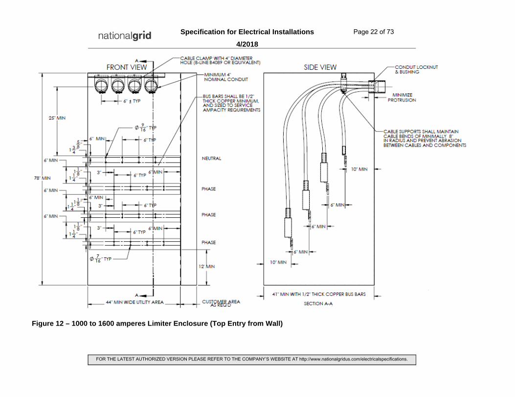
1. Limiter / Termination Enclosure:
a. Customer installed and owned in a location mutually agreed upon by the Company and customer
b. Approximate minimum dimensions of utility area (depth x width x height): 41 in (1041 mm) in x 44 in (1143 mm) in x 78 in (1981 mm)
c. Shall be located at the closest possible point to conduit entrance into the building and be accessible by company personal for cable pulling and splicing
d. The floor area in front of the Limiter / Termination Enclosure shall provide minimally 8 ft of working clearance and be suitable for the installation of anchor inserts.
e. Company conductors shall be terminated onto the customer owned bus work within this enclosure.
f. Shall have provisions for locking and sealing with the Company’s standard padlock
g. Shall meet applicable NEC requirements and listings
h. The bus bars in the Limiter / Termination Enclose shall be arranged such that the neutral bus is closest to the conduit and cable entry as shown in Figures 12 to 14

Specification for Electrical Installations Page 21 of 73
4/2018
FOR THE LATEST AUTHORIZED VERSION PLEASE REFER TO THE COMPANY’S WEBSITE AT http://www.nationalgridus.com/electricalspecifications.
i. Cable limiters and terminations will be provided by the Company, and connections in the enclosure will be made by the Company.
Specification for Electrical Installations Page 22 of 73
4/2018
FOR THE LATEST AUTHORIZED VERSION PLEASE REFER TO THE COMPANY’S WEBSITE AT http://www.nationalgridus.com/electricalspecifications.
Figure 12 – 1000 to 1600 amperes Limiter Enclosure (Top Entry from Wall)

Specification for Electrical Installations Page 23 of 73
4/2018
FOR THE LATEST AUTHORIZED VERSION PLEASE REFER TO THE COMPANY’S WEBSITE AT http://www.nationalgridus.com/electricalspecifications.
Figure 13 – 1000 to 1600 amperes Limiter Enclosure (Bottom Entry from Wall)

Specification for Electrical Installations Page 24 of 73
4/2018
FOR THE LATEST AUTHORIZED VERSION PLEASE REFER TO THE COMPANY’S WEBSITE AT http://www.nationalgridus.com/electricalspecifications.
Figure 14 – 1000 to 1600 amperes Limiter Enclosure (Bottom Entry from Floor)

Specification for Electrical Installations Page 25 of 73
4/2018
FOR THE LATEST AUTHORIZED VERSION PLEASE REFER TO THE COMPANY’S WEBSITE AT http://www.nationalgridus.com/electricalspecifications.
2. Service Conduits:
a. The junction between customer owned and installed conduits and Company owned and installed conduits shall be at a mutually agreed upon location
b. Shall be minimally 4 inch nominal
c. Number of service conduits and spare conduits shall be determined by the Company
d. Customer shall be responsible for all building foundation penetrations
e. All conduits containing company owned conductors that penetrate the building foundation shall be Rigid Galvanized steel
f. All exposed conduits containing company owned conductors and/or conduits before (up-stream of) metering equipment shall be Rigid Galvanized steel
g. Conduit sweep radii shall be minimally 36 inches
3. Conductor wire-ways / troughs before metering:
a. Customer installed and owned
b. Shall not contain metered or load side conductors
c. Shall be Rigid Galvanized steel, Lockable wire-way / troughs, or incorporated into a securable enclosure
d. Shall be sized in accordance with NEC requirements
4. Service Equipment / Main Disconnect:
a. Customer installed and owned
b. Shall contain only a Single Disconnecting Device before Metering Equipment
c. Shall have a minimum short circuit withstand rating of 100,000 amperes RMS symmetrical
d. Main Over-current Protection shall meet required withstand rating and applicable NEC requirements and listings
5. Metering Equipment:
a. Shall be Cold Sequenced
b. Shall be located as close as possible to the Service Equipment / Main Disconnect in one central location
c. No unmetered conductors shall be installed beyond the central metering location
d. Refer to ESB 750 for appropriate specifications

Specification for Electrical Installations Page 26 of 73
4/2018
FOR THE LATEST AUTHORIZED VERSION PLEASE REFER TO THE COMPANY’S WEBSITE AT http://www.nationalgridus.com/electricalspecifications.
3.0 NETWORK SERVICES FROM CUSTOMER-OWNED TRANSFORMER VAULTS
3.1 GENERAL Regardless of customer’s projected demand, main switch sizes larger than the capacity limitations of the area general network will require the installation of Customer-owned transformer vaults. Capacity limitations are dictated by each particular network system and geographic locations.
For 208Y/120 volt service, installation configurations may consist of two or more Customer-owned transformer vaults with provisions to interconnect with the area general network (Figure 15) or two or more Customer-owned vaults in a spot network arrangement (Figure 16). The Company will determine if a vault is to be interconnected with the area general network or is to be spot network.
All 480Y/277 volt services networks shall require two or more Customer-owned transformer vaults (Figure 16). Minimum service size of 480Y/277 volt services shall be 1200 amperes with monthly billing demand as estimated by the Company of not less than 750 kVA.
Customers shall consult the Company in the early stages of a project with load information, service requirements, and applicable site plans.
Not all service sizes can be supplied from network facilities in all areas.
Figure 15 – Customer-Owned Transformer Vaults with Interconnection to General Network
Specification for Electrical Installations Page 27 of 73
4/2018
FOR THE LATEST AUTHORIZED VERSION PLEASE REFER TO THE COMPANY’S WEBSITE AT http://www.nationalgridus.com/electricalspecifications.
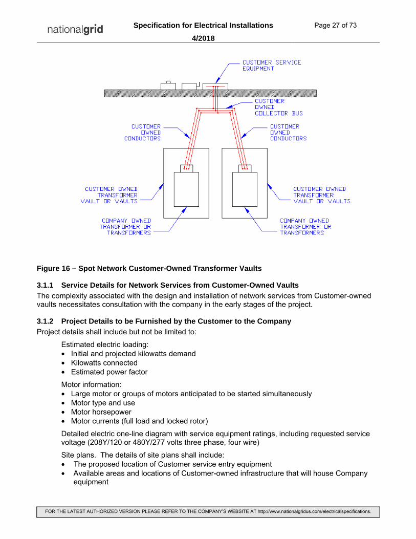
Figure 16 – Spot Network Customer-Owned Transformer Vaults
3.1.1 Service Details for Network Services from Customer-Owned Vaults
The complexity associated with the design and installation of network services from Customer-owned vaults necessitates consultation with the company in the early stages of the project.
3.1.2 Project Details to be Furnished by the Customer to the Company
Project details shall include but not be limited to:
Estimated electric loading: • Initial and projected kilowatts demand • Kilowatts connected • Estimated power factor
Motor information: • Large motor or groups of motors anticipated to be started simultaneously • Motor type and use • Motor horsepower • Motor currents (full load and locked rotor)
Detailed electric one-line diagram with service equipment ratings, including requested service voltage (208Y/120 or 480Y/277 volts three phase, four wire)
Site plans. The details of site plans shall include: • The proposed location of Customer service entry equipment • Available areas and locations of Customer-owned infrastructure that will house Company
equipment

Specification for Electrical Installations Page 28 of 73
4/2018
FOR THE LATEST AUTHORIZED VERSION PLEASE REFER TO THE COMPANY’S WEBSITE AT http://www.nationalgridus.com/electricalspecifications.
3.1.3 Project Details to be Furnished by the Company to the Customer
Project details shall include:
• Service Capability: • Number of transformers to be installed • Maximum service size in amperes at requested voltage • Short Circuit Duty: calculated maximum symmetrical short-circuit current available at the
Customer’s point of attachment to Company equipment • Motor Starting: maximum allowable inrush for starting any motor or combination of motors • Customer Construction: details of the equipment plus facilities required for Company use to
be installed and maintained by the Customer • Estimation of Charges: The Customer will be provided an estimate for labor and materials
that are reimbursable to the Company by the Customer. This estimate will be provided after the Customer has submitted their final project design thereby allowing the Company to finalize the required labor and materials. Note: Changes to the Customer’s final design may require revisions to the estimation of charges and delays to the project.
3.2 LOCATION AND ARRANGEMENT OF SERVICE FACILITIES
3.2.1 Location of Service Conductors
The Company reserves the right to designate the location from the public right-of-way where the Company’s service conductors enter the Customer’s property. This will be determined by the location and suitability of the Company’s existing facilities.
3.2.2 Location of Network Transformers
Network transformers are typically installed in either free-standing above-grade vaults located indoors or below-grade vaults located outdoors. The Company reserves the right to designate the location of network transformers.
The location of network transformers and service equipment shall be as close as practical to minimize the length of secondary voltage conductors.
3.3 REQUIREMENTS, APPROVALS, AND INSPECTIONS
3.3.1 Requirements
This information is in addition to requirements of the National Electrical Safety Code, and supplements the article concerning “Transformer Vaults” in The National Electrical Code, any local requirements that may apply, and all applicable municipal and construction codes. It describes the minimum structural, electrical, and mechanical requirements for the installation of a Customer-owned transformer vault. It is not intended to be a comprehensive document, and should be used only as a guide.
3.3.2 Codes, Standards and Wiring Adequacy
The Customer’s electric service equipment and its installation shall conform to the requirements of the latest edition of the National Electrical Code, all applicable local ordinances and building codes, in addition to the Company requirements and specifications stated herein. It is the Customer’s responsibility to ensure that installed equipment meets all applicable ratings and the installation is certified by a design professional.
3.3.3 National Grid Approval
The Customer shall submit complete final project plans to the Company for approval prior to ordering equipment or beginning construction. This approval is to ensure that the proposed installation conforms to Company requirements.

Specification for Electrical Installations Page 29 of 73
4/2018
FOR THE LATEST AUTHORIZED VERSION PLEASE REFER TO THE COMPANY’S WEBSITE AT http://www.nationalgridus.com/electricalspecifications.
3.3.4 Local Authority Approval
To protect the Customer’s interests as well as its own, the Company will require the Customer to furnish satisfactory evidence of meeting applicable code requirements of the vault installation prior to the Company energizing the service. This shall be in the form of approval by the Local Authority having Jurisdiction.
3.4 VAULT EASEMENT AGREEMENT
Execution of easement(s) drafted by the Company will be required prior to the installation of any Company equipment in the vault or on private property, and prior to the service being energized.
3.5 DIVISION OF RESPONSIBILITIES
The Customer is responsible for providing, installing, owning, and maintaining the following:
• Vault(s), complete with ventilation, lighting, and other accessories detailed in this document
• Ducts, manholes, and conduit between the Company’s facilities and the Customer’s vault(s)
• Openings through building foundation or walls for conduit
• Means of equipment access
• Fire suppression system (where required by local and state building codes and fire protection code)
• Secondary conductors between Customer’s service equipment and the vault(s)
• For spot network application - secondary collector bus
• For 480Y/277 volt spot network application - ground fault protection system
The Company will provide, install, own, and maintain the following:
• Transformers and accessory equipment
• Primary cables
• For 208Y/120 volt vault(s) interconnected with the general network - secondary collector bus and secondary cables to interconnect the vault with the general network.

Specification for Electrical Installations Page 30 of 73
4/2018
FOR THE LATEST AUTHORIZED VERSION PLEASE REFER TO THE COMPANY’S WEBSITE AT http://www.nationalgridus.com/electricalspecifications.
3.6 SERVICE CAPABILITY
Refer to the following table for service capability. Maximum service capability varies depending on the actual location in each specific network. The number of transformer units required for each particular location will vary depending on the specific network. The Company shall be consulted for requirements specific to the location for which service is requested.
The maximum number of main disconnecting devices shall be reviewed by the Company prior to the purchase of equipment.
Service Capability Service Voltage Maximum Number of
Transformer Units ≤ 3000 A 208Y/120 V 2
3001 A – 6000 A 208Y/120 V 3 6001 A – 8000 A 208Y/120 V 4 1200 A – 4000 A 480Y/277 V 3 4001 A – 8000 A 480Y/277 V 4
Notes 1. Maximum service size shall be 8000 amperes. Services shall be limited to two 4000 ampere main disconnects. 2. Service capability limitations and variations are dependent on actual location in specific network. The number of transformer units required for each particular location will vary depending on the specific network. The Company shall be consulted for requirements specific to the location for which service is requested. 3. Not all service sizes can be supplied from network facilities in all areas.
Table 1 – Service Capability
3.7 VAULT DESIGN, LOCATION, AND ACCESS
3.7.1 All Vaults
The following information provides minimum requirements for vaults and is subject to change depending on vault location, means of equipment access, and means of personnel access. The vault shall be under the sole control of the Company. Access shall be limited to authorized Company personnel only, or other personnel with the Company’s agreement and representative in attendance.
The vault location and means of access must be acceptable to the Company. The Customer shall provide a vault design with detailed construction plans for the Company’s review. The design must be agreed upon by the Company prior to the start of vault construction.
The Customer must provide the Company a reasonable means of 24 hour-a-day, 7 days a week access to the vault. If access to the vault requires Company personnel to enter the building, the Customer must also provide the Company a reasonable means of 24 hour-a-day, 7 days a week access to the building.
It is the purpose of the transformer vault to isolate the transformers and other apparatus and to confine any fire that might be caused by the failure of any of the apparatus.4 The Customer’s design, construction, and maintenance of the vault structure and its appurtenances must reflect this concern of containment. Location of the vault access openings should be selected so as to minimize the possibility of injury in the event of a fire.
The vault shall be located so that it will be permanently free from moisture and other contaminants. If the vault location is subject to water accumulation or possible flooding, the Customer, at his expense,
4 McPartland, F.F., et al., National Electrical Code Handbook, 18th edition, McGraw-Hill, New York, 1984.

Specification for Electrical Installations Page 31 of 73
4/2018
FOR THE LATEST AUTHORIZED VERSION PLEASE REFER TO THE COMPANY’S WEBSITE AT http://www.nationalgridus.com/electricalspecifications.
will be required to make provisions to insure that the vault floor will be free of water at all times. A sump hole in the vault is permitted and in some cases required. A sump pump permanently installed inside the vault is permitted, provided it meets Company requirements for automatic disabling in the presence of insulating fluid. If the floor is pitched towards a sump hole, pitch shall not exceed 1” in 15’.
3.7.2 Building Vaults and Free-Standing Above-Grade Vaults
Vehicular overhead clearance to the vault location of at least 14’-0” must be provided for Company service vehicles at all times. Additional overhead clearance will be required in the area around and above the vaults depending on means of equipment access.
The vault shall be located at grade at an outside wall to facilitate ventilation and access. Access openings shall be located to allow truck approach for initial delivery or replacement of transformers and associated equipment. In some cases, a crane or boom truck may be required for the installation and replacement of equipment. A location at a parking or loading area is preferred. The Customer shall be responsible for installation and removal of all doors, hardware, and other obstructions as required for installation and removal of any Company equipment, both at the time of initial installation and at any time in the future as required by the Company. A clear passageway must be provided in advance of the Company scheduling equipment installation.
Refer to Vault Standard Arrangements in the appendix for minimum access requirements for transformer units and other associated heavy equipment.
Access for personnel, which may be via another route, shall be at least 3'-0" wide x 7'-0" high.
A route through the building for heavy equipment access is not recommended. Should the Customer select a route through the building for heavy equipment access, rigging costs and incremental labor expenses incurred by the Company will be billable to the Customer.

Specification for Electrical Installations Page 32 of 73
4/2018
FOR THE LATEST AUTHORIZED VERSION PLEASE REFER TO THE COMPANY’S WEBSITE AT http://www.nationalgridus.com/electricalspecifications.
Refer to Table 2 and the applicable figures in the appendix for standard vault arrangements and dimensions.
Maximum Number of Transformer
Units
Maximum kVA for each Transformer
Unit
Maximum Primary Voltage
Service Voltage Applicable Figures
2 1000 15 kV 208Y/120 V 17 3 1000 15 kV 208Y/120 V 18 4 1000 15 kV 208Y/120 V 19 2 1500 15 kV 480Y/277 V 20 3 1500 15 kV 480Y/277 V 21 4 1500 15 kV 480Y/277 V 22 2 2000 15 kV 480Y/277 V 23 3 2000 15 kV 480Y/277 V 24 4 2000 15 kV 480Y/277 V 25 2 2500 15 kV 480Y/277 V 26 3 2500 15 kV 480Y/277 V 27 4 2500 15 kV 480Y/277 V 28 2 1000 23 kV 208Y/120 V 29 3 1000 23 kV 208Y/120 V 30 4 1000 23 kV 208Y/120 V 31 2 1000 23 kV 480Y/277 V 29 3 1000 23 kV 480Y/277 V 30 4 1000 23 kV 480Y/277 V 31 2 1500 23 kV 480Y/277 V 32 3 1500 23 kV 480Y/277 V 33 4 1500 23 kV 480Y/277 V 34 2 2000 23 kV 480Y/277 V 35 3 2000 23 kV 480Y/277 V 36 4 2000 23 kV 480Y/277 V 37 2 2500 23 kV 480Y/277 V 38 3 2500 23 kV 480Y/277 V 39 4 2500 23 kV 480Y/277 V 40 2 1500 35 kV 480Y/277 V 41 3 1500 35 kV 480Y/277 V 42 4 1500 35 kV 480Y/277 V 43 2 2000 35 kV 480Y/277 V 44 3 2000 35 kV 480Y/277 V 45 4 2000 35 kV 480Y/277 V 46 2 2500 35 kV 480Y/277 V 47 3 2500 35 kV 480Y/277 V 48 4 2500 35 kV 480Y/277 V 49
Table 2 – Standard Arrangements - Building Vaults and Free-Standing Above-Grade Vaults
3.7.3 Below-Grade Vaults Located Outdoors
Vehicular overhead clearance to the vault location of at least 14’-0” must be provided for Company service vehicles at all times. Additional overhead clearance will be required in the area around and above the vaults depending on means of equipment access. Vaults shall be located away from building entrances where possible.
The vault shall have access openings located to allow truck approach with boom or crane installation for initial delivery and replacement of transformers and associated equipment. The area above and

Specification for Electrical Installations Page 33 of 73
4/2018
FOR THE LATEST AUTHORIZED VERSION PLEASE REFER TO THE COMPANY’S WEBSITE AT http://www.nationalgridus.com/electricalspecifications.
around all equipment access openings shall be designed for unobstructed equipment access. The Customer shall be responsible for installation and removal of all obstructions as required for installation and removal of any Company equipment, both at the time of initial installation and at any time in the future as required by the Company. A clear passageway must be provided in advance of the Company scheduling equipment installation.
Refer to the latest edition of National Grid material specification MS 3492 and MS 3493 for acceptable pre-cast below-grade vault dimensions and access requirements. An individual below-grade vault is required for each transformer. Refer to Figure 50 in the Appendix.
For specialized installations or installations in which a pre-cast vault cannot be used, refer to Table 3 for minimum access requirements for transformer units and other associated equipment.
Maximum kVA
for each Transformer
Unit
Maximum Primary Voltage
Service Voltage
Minimum Clear Opening for
Equipment Access (width x length)
1000 15 kV 208Y/120 V 6’-0” W x 11’-7” L
1500 15 kV 480Y/277 V 6’-2” W x 12’-3” L
2000 15 kV 480Y/277 V 6’-10” W x 13’-0” L
2500 15 kV 480Y/277 V 7’-4” W x 14’-8” L
Table 3 – Minimum Access Requirements for non-precast Below-Grade Vaults
3.8 CONSTRUCTION
3.8.1 Company Requirements, Specifications, and Inspection
The Customer shall refer to the Company’s “Specifications for Electrical Installations Underground Commercial Distribution (UCD) Installation and Responsibility Guide” (Electric System Bulletin No. 759B) for requirements and standards for the following:
• Concrete Specifications • Conduit Construction • Approved Material - conduit and accessories, manhole frames and covers
The Customer shall refer to the Company’s specifications and requirements for precast transformer vaults, hatchways, ladders, and accessories. This information will be provided separately.
All phases of construction must be inspected by the Company and must meet Company requirements prior to the installation of any Company equipment. See also “Construction Inspection” section in this document for further details.
3.8.2 Foreign Structures
Pipes, duct systems, or other items foreign to the vault electrical installation shall not enter or pass through the vault. Systems enclosed in concrete, masonry, etc., to the applicable thickness specified in “Walls, Roof, and Floor” section of this document are not considered to be in the vault provided there is no interference in operation, maintenance, or construction of the vault. All such cases must be submitted to the Company for review.
3.8.3 Code Requirements
It is the Customer’s responsibility to determine that the fire rating of the vault will meet all applicable codes and regulations for silicone-filled equipment in a building. Silicone is a “less-flammable” insulating fluid.

Specification for Electrical Installations Page 34 of 73
4/2018
FOR THE LATEST AUTHORIZED VERSION PLEASE REFER TO THE COMPANY’S WEBSITE AT http://www.nationalgridus.com/electricalspecifications.
Although the following structural requirements are believed to be conservative, it is the customer’s responsibility to determine that the vault will meet all national and local structural codes. The consultation of a licensed design professional is encouraged.
3.8.4 Walls, Roof, and Floor
3.8.4.1 Building Vaults and Free-Standing Above-Grade Vaults
The quality of materials used in vault construction shall be of approved grade, as determined by the applicable codes and Company requirements. Building walls and floors (new or existing) meeting the following requirements may serve as part of the vault.
The vault in its entirety shall have a fire rating of three hours, minimum.
Walls shall be solid masonry or concrete construction and free of holes, deep scars, cracks, or other breaks. All concrete work shall conform to ACI 318-11; all masonry work shall conform to ACI 530-11.
All walls shall be structurally connected to the floor and ceiling.
Walls up to a maximum of 16’ in height shall be constructed to the following minimum standards.
• 4500 psi Concrete – 6” thick reinforced with #5 bars @ 10” grid (Figure 51 in the Appendix)
• 4500 psi Concrete – 8” thick reinforced with #4 bars @ 10” grid (Figure 52 in the Appendix)
• CMU – 12” thick, fully grouted, reinforced with 2 - #4 bars @ 8” OC (Figures 53 & 54 in the Appendix)
Walls greater than 16’ in height will require a design specific to the installation by a design professional.
The floor of a building vault or free-standing above grade vault located with supporting soil directly below it shall be constructed to the following minimum construction standards:
• 4500 psi Concrete – 6” thick reinforced with #4 bars @ 12” grid (Figure 55 in the Appendix)
If a vault does not have supporting soil below the floor, in the case of a building vault located directly above the basement level, a structural design professional should be consulted to design new or verify the adequacy of the existing floor for the proposed vault location and company equipment.
Any portion of a vault roof located at grade and outside shall meet the requirements of section 3.8.4.2. The roof of building vaults located indoors shall meet applicable local codes and a 3-hour fire rating. Gypsum board shall not be used to achieve the 3-hour fire rating.
The roof of free standing above-grade vaults shall meet a 3-hour fire rating, minimum. A licensed design professional should be consulted for the structural design of the roof specific for the environmental loading conditions in accordance with ASCE-7-10 “Minimum Design Loads for Buildings and Other Structures” and applicable local building codes.
Floor criteria listed above will not exempt free standing above-grade vaults from meeting foundation depth and frost-protection requirements in accordance with national and local building codes.
3.8.4.2 Below Grade Vaults Located Outdoors
Below-grade vaults located outdoors shall be either field cast (reinforced concrete minimum thickness 12”) or precast units. Both styles shall have removable access panels, hatchway gratings, and personnel access hatchways and/or manhole covers in locations specified by the Company’s Engineer. Partition walls built to create a below-grade sidewalk vault from former basement space shall conform to the requirements of building vaults. The customer shall equip the vault with all related accessories such as ladders, lighting, and pull-eyes. All materials shall be in accordance with the Company’s Construction Standards and Material Standards.

Specification for Electrical Installations Page 35 of 73
4/2018
FOR THE LATEST AUTHORIZED VERSION PLEASE REFER TO THE COMPANY’S WEBSITE AT http://www.nationalgridus.com/electricalspecifications.
All covers, grating, and removable panels located at grade shall be designed to meet H-20 tractor-trailer loading requirements as outlined in Figure 56 in the Appendix.
All steel grating and field covers shall have anti-slip surface treatment in compliance with the GALVAGRITTM Specification on Page 69 in the Appendix.
3.8.5 Floor, Ceiling, and Wall Loading (Weights)
The weight of the Company’s equipment must be supported in the final locations and in all other locations that might arise during initial installation and future maintenance. Provisions shall be made to support the maximum transformer that would be installed in the vault, even though the initial transformer installation may be less than maximum. Weights of standard units are provided in Table 4.
The Customer may be required to provide wall, ceiling, and floor penetrations to accommodate miscellaneous Company equipment or supports. The Customer may also be required to provide and install anchors and rods to support Company cables and other miscellaneous equipment. Locations and maximum weights to be supported will be specified by the Company.
Service Voltage Primary Voltage Transformer kVA Maximum Weight
per Unit
208Y/120 V Up to 23 kV Up to 1000 18,000 lbs
480Y/277 V Up to 23 kV Up to 1000 18,000 lbs
480Y/277 V Up to 23 kV 1500 20,000 lbs
480Y/277 V Up to 23 kV 2000 & 2500 32,000 lbs
480Y/277 V 34.5 kV Up to 2500 32,000 lbs
Table 4 – Network Unit Weights
3.8.6 Doors (Building Vaults and Free-Standing Above-Grade Vaults)
Type of doors must be as approved for Class A situations in accordance with National Fire Protection Association for protection of openings in walls and partitions against fire. Doors shall be set in a metal frame, with the metal rabbeted all around and held tight in rabbet by a fire-rated latch and strike. Additional door hardware required is as follows: (a) butt hinges with non-removable pins, (b) automatic door closer, (c) panic bars on vault side of doorways to allow quick egress, and (d) lock sets to accept the Company’s standard cylinder, which will be furnished by the Company.
1. Double door arrangements can either have panic hardware installed on one door with an inactive / fixed second door if egress requirements allow, or both doors can be equipped with panic hardware if equipped with a removal post / stanchion.
2. Depending on service area and application the company’s standard cylinder will be either a Wilson Bohannan (WB) cylinder or a Best®, figure eight, seven pin cylinder.
3. The number, location, and clear opening of doors required will be specified by the Company. Refer to Figures 17 through 49. Additional doors for personnel access may be required and shall be a minimum of 3'-0" wide x 7'-0" high.

Specification for Electrical Installations Page 36 of 73
4/2018
FOR THE LATEST AUTHORIZED VERSION PLEASE REFER TO THE COMPANY’S WEBSITE AT http://www.nationalgridus.com/electricalspecifications.
Doors shall be hung on 3 hinges per door (minimum), or 3 hinges per leaf (minimum) if a double door, and shall open out from the vault. Doors shall fit closely in the door frame and be secure and immovable when closed. Door sills shall be located 6" above the vault floor.
Identifying signs will be furnished and installed by the Company on the outside of all vault doors and adjacent walls.
The Customer shall be responsible for internally lit exit signs as required by local applicable codes.
The doors shall have the same UL approved fire rating as the wall in which the door is installed.
3.8.7 Ladders (Below-Grade Vaults)
For below-grade vaults, ladders must be permanently installed. All ladders installed for the purpose of entering a transformer vault shall comply with OSHA 190.27 for “Fixed Ladders” and OSHA 3124 for “Stairways and Ladders” unless the specifications outlined in the following section are more stringent.
1. Ladders are to be constructed of a non-corrosive material or be treated to resist corrosion (hot-dipped galvanized). Wood is unacceptable for use in vaults. The ladder shall be constructed entirely of the same material; this prevents electrolytic action.
2. Ladders shall be bonded to the Vault Grounding Loop as shown in Figure 44.
3. Ladder loading shall be in accordance with OSHA 3124.
4. Ladders in transformer vaults shall have side rails. Individual rung ladders are unacceptable.
5. Ladders shall be angled as dictated by OSHA 1910.27(e)(1) – “preferred pitch” but shall not exceed an 85 degree angle. Refer to Figure 41 below.

Specification for Electrical Installations Page 37 of 73
4/2018
FOR THE LATEST AUTHORIZED VERSION PLEASE REFER TO THE COMPANY’S WEBSITE AT http://www.nationalgridus.com/electricalspecifications.
Figure 41 – Annotated OSHA Figure D-11 – Pitch of Fixed Ladders
6. Rung spacing and design shall comply with OHSA 1910.27(b)(1). Refer to Figure 42.
Rungs shall be spaced at 12 inches. The rungs shall be a minimum of ¾ inches in diameter. Rungs shall be a minimum of 16 inches in length. The distance between the centerline of the rungs to the nearest permanent object shall be 7 inches.
85°

Specification for Electrical Installations Page 38 of 73
4/2018
FOR THE LATEST AUTHORIZED VERSION PLEASE REFER TO THE COMPANY’S WEBSITE AT http://www.nationalgridus.com/electricalspecifications.
Figure 42 – OSHA Figure D-2
7. The ladder shall extend to within 1 inch of the entrance hatchway in order to provide safe
stepping transition to the ladder.

Specification for Electrical Installations Page 39 of 73
4/2018
FOR THE LATEST AUTHORIZED VERSION PLEASE REFER TO THE COMPANY’S WEBSITE AT http://www.nationalgridus.com/electricalspecifications.
8. An extension device shall be attached at the top or be integral part of the ladder that will extend a minimum of 42” above the top rung of the ladder. The device is to be constructed of a non-corrosive or corrosive resistant material. An example of a device that attaches to the ladder is the Bilco – “ladderup” unit. Refer to Figure 43.
Figure 43 – Ladder Extension
3.8.8 Lighting and Convenience Outlets
The Customer shall install, maintain, and provide energy for a lighting system and 120 volt duplex convenience outlets in the vault. The lighting system and outlets shall be supplied from dedicated branch circuits (30 amperes minimum) which shall be clearly labeled as “Utility Vault” at the Customer’s distribution panel. Locations of lamps and convenience outlets shall be shown on the Customer’s vault design and shall be reviewed by the Company. A switch shall be mounted on the inside wall at every access point so that the lights may be turned on or off at any point of entry. A red pilot lamp connected so as to light when vault lighting is on shall be located outside the vault and shall be visible at all entrance doors. All electrical wiring shall be housed in rigid electrical conduit or electrical metal tubing. Covers of conduit fittings shall be gasketed.
Lighting and power systems installed in below-grade vaults located outdoors shall use materials suitable for the environment.
Wall-mounted fixtures are required for below-grade vaults, and are preferred for all other locations. Fixtures shall be equipped with a globe, guard, and a standard-base 120 volt lamp. Ceiling-mounted fixtures with a standard-base lamp are an alternative for areas remote from live parts if fixture height is not more than 11’-0” and there is no interference with Company equipment or access hatchways. Fixture heights in excess of 11’-0” may be allowed for certain applications, but require advance review by the Company’s engineer.
In the event the Customer’s fixtures are not standard base and do not accommodate the Company’s standard bulbs, the Customer will be required to provide all replacement bulbs, including a supply of spare bulbs at the time of initial installation.
Lighting shall be designed for a minimum of 10 foot-candle illumination. Fixtures must be provided in the area opposite each network protector.

Specification for Electrical Installations Page 40 of 73
4/2018
FOR THE LATEST AUTHORIZED VERSION PLEASE REFER TO THE COMPANY’S WEBSITE AT http://www.nationalgridus.com/electricalspecifications.
3.8.9 Ventilation
3.8.9.1 Natural Ventilation Natural ventilation shall be used only when a vault roof can be utilized to exhaust heat. Vent openings in the roof of a below-grade structure can also serve as equipment and personnel access hatchways. In this case, the openings shall be in accordance with the Company’s Construction Standards and Material Standards for precast vaults (provided upon request). Openings shall have net free air space as follows:
10’ x 22’ (inside dimensions) vault – 63 square feet of net free air space.
The Customer is responsible for insuring the design meets all applicable local and state building code and fire protection codes. The ventilation design shall be submitted to the Company for review, and the Customer shall submit ventilation calculations for the Company’s records.
3.8.9.2 Air Conditioning
Air conditioning of transformer vaults is permitted. Vault air conditioning system shall be separate from the building system and shall be in accordance with state and local codes.
3.8.9.3 Forced Ventilation
The Customer will, at his expense, install, maintain, and provide energy for a forced air, thermostatically-controlled ventilation system designed to move outside air through the vault.
Extreme caution must be exercised in the design, routing, and installation of forced ventilating systems. Exhaust openings to outside walls should not be located adjacent to other openings that serve or could serve as air intakes. Exhaust openings should be located as far as possible from doors, windows, fire escapes, and combustible material, and at an adequate elevation above grade.
Duct facilities should not be routed through areas where system leaks (possibly initiated by explosion) could result in the escape of potentially toxic gases or residue to occupied areas. Vaults located below grade must have forced intake and natural exhaust.
Intake and exhaust openings shall be equipped with rustproof metal louvers and 1/2" mesh rustproof screens where they meet the outside air. The exhaust ducts shall be located high in the vault and the intake ducts low, both suitably spaced to provide air circulation around all transformers. Fire dampers, when required by local and state building code and fire protection code, shall be a minimum of #10 gauge galvanized steel constructed in accordance with ANSI/UL 555 “Standard for Fire Dampers.” Fire damper fuse links shall allow dampers to fall or rotate closed in the event of fire, and not as a result of excessive transformer temperature. In addition, the dampers shall be arranged so that operation of the blower does not hold them open.
Ventilation capacity is to be furnished for the maximum capacity of the vault, even though the initial transformer installation may be less than maximum capacity.
Ventilation design shall be based on the following.
• Heat dissipation rates shall be as listed in Table 5;
• Maximum ambient temperature of the vault shall not exceed 104°F near the transformers, and average ambient temperature for any 24-hour period shall not exceed 86°F;
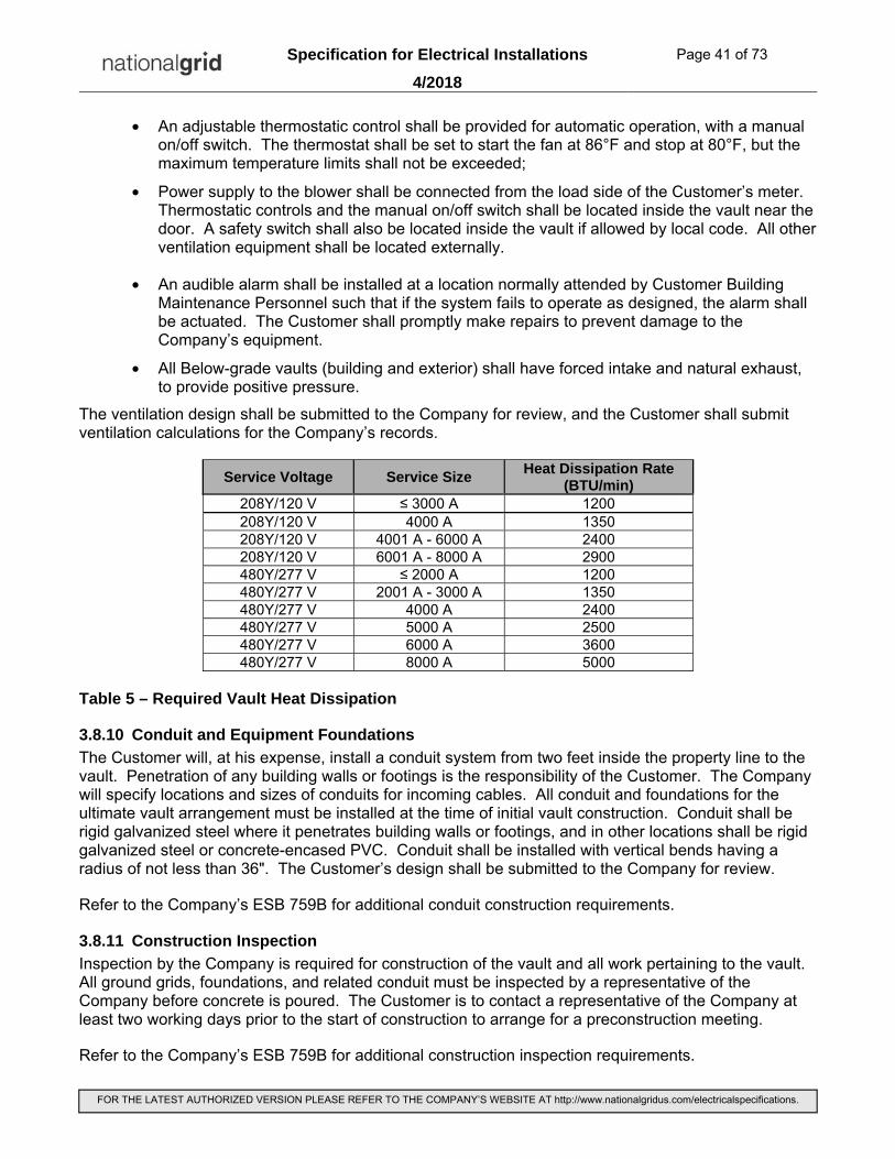
Specification for Electrical Installations Page 41 of 73
4/2018
FOR THE LATEST AUTHORIZED VERSION PLEASE REFER TO THE COMPANY’S WEBSITE AT http://www.nationalgridus.com/electricalspecifications.
• An adjustable thermostatic control shall be provided for automatic operation, with a manual on/off switch. The thermostat shall be set to start the fan at 86°F and stop at 80°F, but the maximum temperature limits shall not be exceeded;
• Power supply to the blower shall be connected from the load side of the Customer’s meter. Thermostatic controls and the manual on/off switch shall be located inside the vault near the door. A safety switch shall also be located inside the vault if allowed by local code. All other ventilation equipment shall be located externally.
• An audible alarm shall be installed at a location normally attended by Customer Building Maintenance Personnel such that if the system fails to operate as designed, the alarm shall be actuated. The Customer shall promptly make repairs to prevent damage to the Company’s equipment.
• All Below-grade vaults (building and exterior) shall have forced intake and natural exhaust, to provide positive pressure.
The ventilation design shall be submitted to the Company for review, and the Customer shall submit ventilation calculations for the Company’s records.
Service Voltage Service Size Heat Dissipation Rate
(BTU/min) 208Y/120 V ≤ 3000 A 1200 208Y/120 V 4000 A 1350 208Y/120 V 4001 A - 6000 A 2400 208Y/120 V 6001 A - 8000 A 2900 480Y/277 V ≤ 2000 A 1200 480Y/277 V 2001 A - 3000 A 1350 480Y/277 V 4000 A 2400 480Y/277 V 5000 A 2500 480Y/277 V 6000 A 3600 480Y/277 V 8000 A 5000
Table 5 – Required Vault Heat Dissipation
3.8.10 Conduit and Equipment Foundations
The Customer will, at his expense, install a conduit system from two feet inside the property line to the vault. Penetration of any building walls or footings is the responsibility of the Customer. The Company will specify locations and sizes of conduits for incoming cables. All conduit and foundations for the ultimate vault arrangement must be installed at the time of initial vault construction. Conduit shall be rigid galvanized steel where it penetrates building walls or footings, and in other locations shall be rigid galvanized steel or concrete-encased PVC. Conduit shall be installed with vertical bends having a radius of not less than 36". The Customer’s design shall be submitted to the Company for review.
Refer to the Company’s ESB 759B for additional conduit construction requirements.
3.8.11 Construction Inspection
Inspection by the Company is required for construction of the vault and all work pertaining to the vault. All ground grids, foundations, and related conduit must be inspected by a representative of the Company before concrete is poured. The Customer is to contact a representative of the Company at least two working days prior to the start of construction to arrange for a preconstruction meeting.
Refer to the Company’s ESB 759B for additional construction inspection requirements.

Specification for Electrical Installations Page 42 of 73
4/2018
FOR THE LATEST AUTHORIZED VERSION PLEASE REFER TO THE COMPANY’S WEBSITE AT http://www.nationalgridus.com/electricalspecifications.
3.8.12 Fluid Volume and Liquid Curb (Building Vaults and Free-Standing Above-Grade Vaults)
An effective liquid curb at least 6" high will be installed as part of the vault design; all conduits and floor and wall penetrations will terminate above that level. Door sills are acceptable as part of the liquid curb.
Volumes of fluid for the largest transformers that could be installed in the vault are provided in Table 6.
Service Voltage Primary Voltage Transformer kVA Fluid Volume per
Transformer (gal)
208Y/120 V Up to 15 kV Up to 1000 400 208Y/120 V 23 kV Up to 1000 500 480Y/277 V Up to 15 kV Up to 1500 500 480Y/277 V Up to 15 kV 2000 & 2500 650 480Y/277 V 23 kV Up to 2500 650 480Y/277 V 34.5 kV Up to 2500 700
Table 6 - Fluid Volume
3.8.13 Audible Sound Levels
Should the Customer be concerned about any possible undesirable sound or vibration transmission to other portions of the building, any soundproofing is his responsibility. Should the Customer desire to support the transformers on soundproofing devices, any device should be fabricated so as not to exceed 2" thickness and so that it will hold its dimensions over time given the weights involved and variation in vault temperature.
Transformers are designed so that the average sound level does not exceed values specified in the current issue of IEEE/ANSI C57.12.40, Standard Requirements for Secondary Network Transformers - Subway and Vault Types (Liquid Immersed).
3.8.14 Sealing of Customer Conduits
The Customer shall seal conduits containing customer owned conductors and empty / spare conduits with a fire stop sealant.
3.9 FIRE SUPPRESSION SYSTEMS
Where required by the local and state building code and fire protection code, the Company will permit a water fire suppression system to be installed in the vault provided the Customer is responsible for and insures the following conditions are met.
3.9.1 Design and Installation
3.9.1.1 The system must take into consideration the locations of Company equipment. The system shall be designed and installed so that there is no interference in the construction, operation, or maintenance of the vault or equipment therein. Location of all pipes, detectors, sprinkler heads, and nozzles must not interfere with any of the Company’s electrical equipment or access thereof. The system must be designed so that it can be maintained without removal, relocation, or de-energizing of any Company equipment.
3.9.1.2 The Customer’s proposed design for any fire protection system must be submitted to the Company for review. The design must be reviewed and agreed upon by the Company prior to the start of vault construction. Information must be site-specific and plans must be provided showing location of detectors and sprinkler heads or nozzles. All plans must be drawn to scale, and the Company’s equipment must be accurately located on the plans. Information must include type of system and a

Specification for Electrical Installations Page 43 of 73
4/2018
FOR THE LATEST AUTHORIZED VERSION PLEASE REFER TO THE COMPANY’S WEBSITE AT http://www.nationalgridus.com/electricalspecifications.
complete step-by-step description of the system’s sequence of operation, including means of fire detection and number of devices required to be in alarm before the system actuates.
3.9.1.3 The suppression system shall be a supervised double-interlock cross-zoned pre-action system. A pre-discharge alarm shall be provided inside the vault to indicate that water has entered the system.
3.9.1.4 The system shall be dedicated for protection in the vault area only and pipes shall not fill for an event in areas other than the vault.
3.9.1.5 Where possible while still meeting code requirements, the system shall be designed so that sprinkler discharge does not reach the secondary collector bus or any other live uninsulated parts. Location of Company equipment will be shown on drawings after the vault electrical design is complete.
3.9.1.6 Scaled and dimensioned drawings, prepared and sealed by the Customer’s design professional, shall be provided showing location of sprinkler heads in the electric vault and calculated range of water dispersion from sprinkler heads relative to the Company’s secondary collector bus. All equipment shall be accurately located on the plans.
3.9.2 Construction
3.9.2.1 All construction must conform to the design drawings reviewed and agreed to by the Company, and must be inspected by a representative of the Company as it pertains to the Company’s vault equipment before the system is placed in service. The Company’s engineer must review and agree to any proposed deviation from plans already reviewed and agreed to by the Company.
3.9.3 Variances
3.9.3.1 Should a Code variance be required for any reason, it is the Customer’s responsibility to obtain such variances from appropriate authority having jurisdiction and provide written notice to the Company.
3.9.4 Easement Language
Language concerning any fire suppression system will be included in the Company’s standard vault easement agreement (see “Vault Easement Agreement” section in this document) and will include, but may not necessarily be limited to, the following.
• The Customer assumes sole responsibility for proper operation of the fire suppression system.
• The Company assumes no liability for any result or consequences of a fire suppression system that has the potential to apply water on an oil or silicone insulating fluid fire.
The Customer shall indemnify and hold the Company harmless for any damages resulting from operation, misoperation, or inadvertent system discharge of a fire suppression system. Should the system misoperate or discharge unnecessarily, the Customer will be responsible for damage to the Company’s equipment and any cost for vault cleanup, as well as Company representative in attendance required while the Customer is working in the vault.
3.10 ELECTRICAL
3.10.1 Grounding
The following grounding criteria are for the sole purpose of grounding Company-owned equipment in the vault.
The Customer shall provide a galvanized steel conduit with two (2) 500 kcmil copper 600 volt insulated conductors therein from the vault to the street side of the building water meter for use by the Company. The conductors are to attach to the water service pipe at the street side of the water meter and have

Specification for Electrical Installations Page 44 of 73
4/2018
FOR THE LATEST AUTHORIZED VERSION PLEASE REFER TO THE COMPANY’S WEBSITE AT http://www.nationalgridus.com/electricalspecifications.
“tails” in the vault of sufficient length to allow easy unspliced attachment to the vault ground bus. Where the water supply is non-metallic or not accessible, exothermic bonding to building steel is acceptable per applicable state and local codes.
Additionally, for below-grade or freestanding vaults, pigtails shall be taken from the structure’s reinforcing steel as shown in Figure 44.
Note 1 – Minimally two 4/0 tails bonded to vault rebar are required. Additional 4/0 tails may be required for vaults that are cast with separate floor sections. Ground bonding shall connect floor and all wall sections. Epoxy coated rebar is not allowed.
Figure 44 – Vault Grounding Loop
The Customer shall suitably ground incoming conduits and ventilating and convenience outlet systems as required by applicable codes.
The customer shall bond all customer owned and installed equipment in the vault.

Specification for Electrical Installations Page 45 of 73
4/2018
FOR THE LATEST AUTHORIZED VERSION PLEASE REFER TO THE COMPANY’S WEBSITE AT http://www.nationalgridus.com/electricalspecifications.
3.10.2 Interrupting
The calculated maximum symmetrical three phase short-circuit current available at the Customer’s point of attachment to the Company’s equipment in the proposed vault for a zero impedance fault will be as follows:
• For 208Y/120 V network services with customer owned vaults interconnected with the General Network - as provided by the Company’s Engineer. Maximum available calculated short-circuit current will not exceed 200,000 amperes.
• For 208Y/120 V or 480Y/277 V spot network service - see Table 7
Spot Network Service Voltage
Spot Network Maximum Service
Capability
Maximum Available Short Circuit Current (calculated symmetrical amperes)*
208Y/120 V ≤ 3000 A 120,000 208Y/120 V 4000 A 135,000 208Y/120 V 6000 A 180,000 208Y/120 V 8000 A 240,000 480Y/277 V ≤ 2000 A 100,000 480Y/277 V 4000 A 104,000 480Y/277 V 6000 A 112,000 480Y/277 V 8000 A 186,000
*Calculated at the customer connection with Company owned equipment (Refer to Division of Responsibilities section)
Table 7 - Spot Network Service - Available Short Circuit Current
3.10.3 Secondary Conductors and Construction
The Customer is responsible for installing secondary service conductor and conduit into the vault, and for providing a method of attachment to the Company’s equipment in the vault. All conductor entering or within the vault shall be copper. Review by the Company will be required in advance. Point of connection will be at the Company’s equipment. Attachment will be by Company personnel.
Secondary cable entering the vault shall be XHHW type, soft drawn copper. The Customer shall provide the required connectors. Terminal lugs shall be compression-type tinned copper, long barrel, with a two-hole pad having standard NEMA drillings (two holes sized for 1/2" bolts, spaced 1-3/4" on center). Maximum lug width shall be 2". Connectors, bolts, nuts, flat washers and lock washers will be supplied by the Customer. Point of connection will be at the Company’s equipment.
The proposed location of the Customer’s secondary conduits must be reviewed by the Company in advance of construction. Conduits must be located such that adequate vertical and horizontal clearance to the Company’s equipment is maintained, conduits will not present an obstruction to movement in the vault, and adequate working space is maintained.
3.10.3.1 Secondary Collector Bus – 208Y/120 volt Interconnected with the General Network
The Company will install, own, and maintain the secondary collector bus.

Specification for Electrical Installations Page 46 of 73
4/2018
FOR THE LATEST AUTHORIZED VERSION PLEASE REFER TO THE COMPANY’S WEBSITE AT http://www.nationalgridus.com/electricalspecifications.
3.10.3.2 Secondary Collector Bus – Spot Network
The Customer will design, construct, install, own, and maintain the secondary collector bus. The bus shall be located outside the vault.
The combined strength of the conductors and insulating material together with the supporting members shall be capable of withstanding the forces exerted by a three phase fault of the magnitude specified by the Company.
Neutral bus conductor ampacity shall be equal to the phase conductor ampacity.
3.10.4 Protective Device Coordination
It is essential that the Customer’s main switch or fuse coordinate with the Company’s protective devices. Upon request, the Company will provide the Customer with time-current characteristics with which their main switch must coordinate.
3.10.5 Ground Fault Protection System - 480Y/277 volt Network Service
In order to provide ground fault protection on the “line side” of the Customer’s ground fault sensors (i.e. main service disconnecting devices), the Company requires the installation of a scheme that will trip all of the Company-owned Network Transformer’s “Low-side” network protectors for an arcing ground fault between the Company-owned Network Transformers and the Customer-owned main service disconnecting devices.
The Customer shall furnish, design, install, own, and maintain a ground fault protection scheme on the “line side” of the Customer’s ground fault sensors (i.e. main service disconnecting devices) except that the Company will perform all work within the manholes and vaults including installation of the Customer’s current transformer, where required, in each of the network transformer bond connections.
The Customer, in furnishing this protection, assumes the sole risk and responsibility for damage to his own equipment as would be the case if he supplied his own network protectors.
The Customer shall reimburse the Company for all costs incurred by the Company in the installation of the Ground Fault Protection scheme.
The Customer shall provide a Ground Fault Study for the Company’s review including drawings and proposed settings. Drawings shall be submitted for review by the Company in advance of ordering materials.
The scheme shall be subject to the following requirements (also refer to Figures 57, 58 and 59 in the Appendix for reference):
Ground Fault Relay (GFR) & Lockout Relay (LOR) Requirements:
• The GFR shall have a pick-up range of 100 – 1200 Amperes.
• The GFR shall trip a lock-out relay (GE Model HEA or equivalent). The LOR shall be “Hand” reset style.
• When possible the GFR and LOR shall be supplied from a 120 volt utility power source. If a 120 volt utility power source is not readily available, the customer shall provide 120 volt power from the source side of the main disconnect.
Current Transformer Requirements:
• The points at which the neutral is grounded and the current transformer locations should be chosen so that unbalanced load currents and zero sequence harmonics due to phase-to-neutral loads are not seen by the ground relays.

Specification for Electrical Installations Page 47 of 73
4/2018
FOR THE LATEST AUTHORIZED VERSION PLEASE REFER TO THE COMPANY’S WEBSITE AT http://www.nationalgridus.com/electricalspecifications.
• The customer is responsible for selecting current transformers that will fit properly around the Company’s neutral to ground bond conductor(s). Neutral to ground bond conductors will be either rectangular bar or multiple insulated conductors.
A 500 watt load with a push button momentary make switch in series shall be connected to the line side of the Customer’s main disconnect device through a fuse (a strip heater is acceptable). It shall be connected in the circuit Phase A to ground, but have the ability to be reconnected to either of the other phases. This will facilitate restoration of service by the Company should the ground fault protection system operate.
Installation:
• The Company will perform all work within the manholes and vault including installation of the Customer’s current transformer(s).
Testing Requirements:
• The system shall provide the capability to test with and without interruption of service.
• All installed current transformers shall be readily accessible by National Grid for the purpose of testing.
• Upon completion of a new or revised 480V spot network installation, National Grid will set and test the system.
3.10.6 Arc Flash Mitigation - 480Y/277 volt Network Service
To provide arc flash mitigation within the vault and on the line side of the Customer’s main disconnecting device on 480Y/277 volt network services, the Company will specify devices to be installed, owned, and maintained by the customer.
3.10.7 Fire Pump Service
A separate service “ahead of the main” for fire pumps and/or emergency lights, if required by the local and state building code and fire protection code, will be permitted. Such a service will be separately metered and billed. The Customer must notify the Company if such a service is required so that it can be incorporated into the Company’s vault electrical design.
3.11 VAULT MAINTENANCE Should the vault or any Customer-owned systems associated with the vault require maintenance or repair, it will be brought to the attention of the Customer who shall promptly make repairs with a Company representative in attendance.
3.11.1 Qualified Personnel
Should repairs to or inspection of Customer-owned equipment require the Customer’s representative to enter the vault, it is the Customer’s responsibility to provide personnel qualified to perform the required maintenance, and qualified and properly equipped to enter the vault space in accordance with applicable regulations, including OSHA regulations for enclosed space entry.
3.11.2 Customer Access to Company-Controlled Spaces within Customer-Owned Facilities
The Company's control of electric spaces in Customer-owned electric facilities is for the sole purpose of protecting the integrity of the Company's energy supply and security of the utility metering equipment. Any costs shall be determined by the Company's filed tariff. In these requirements, "Customer" refers to the Customer or their agent. Under this and all other policies, it is expected and it is the Customer's responsibility to provide a qualified person as defined in the National Electrical Code and any other applicable codes.

Specification for Electrical Installations Page 48 of 73
4/2018
FOR THE LATEST AUTHORIZED VERSION PLEASE REFER TO THE COMPANY’S WEBSITE AT http://www.nationalgridus.com/electricalspecifications.
1. The Company can provide isolation and tagging (and grounding upon customer request), if requested, at the Company’s primary isolation point on the supply line ahead of the Customer's service equipment. However, the Customer is solely responsible for the protection of personnel who work on their de-energized equipment.
2. When the Customer does not require isolation and tagging on the supply line and needs access to Company-controlled electrical spaces for their maintenance purposes, the Company in its sole judgment may determine the ability to grant access to the Customer for the duration established by the Company. When granted, the Company will witness the Customer's placement of their lock immediately after the removal of the Company's lock. Upon notification by the Customer that their work is complete, the Customer shall relinquish access back to the Company and the Company's lock shall be placed immediately upon the removal of the Customer's lock. In each case the transfer shall occur in the presence of both parties. The Company will check its electrical equipment for any signs of tampering.
In the event that the required access is of short duration and the Company's representative remains on site to avoid a second trip, it is understood they are doing so without any supervisory or oversight capacity relative to the Customer.

Specification for Electrical Installations Page 49 of 73
4/2018
FOR THE LATEST AUTHORIZED VERSION PLEASE REFER TO THE COMPANY’S WEBSITE AT http://www.nationalgridus.com/electricalspecifications.
3.12 APPENDICES
Figure 17 – Building & Free-Standing Vault Standard Arrangements, 2 – 1000 kVA, 15 kV
Figure 18 – Building & Free-Standing Vault Standard Arrangements, 3 – 1000 kVA, 15 kV

Specification for Electrical Installations Page 50 of 73
4/2018
FOR THE LATEST AUTHORIZED VERSION PLEASE REFER TO THE COMPANY’S WEBSITE AT http://www.nationalgridus.com/electricalspecifications.
Figure 19 – Building & Free-Standing Vault Standard Arrangements, 4 – 1000 kVA, 15 kV
Figure 20 – Building & Free-Standing Vault Standard Arrangements, 2 – 1500 kVA, 15 kV

Specification for Electrical Installations Page 51 of 73
4/2018
FOR THE LATEST AUTHORIZED VERSION PLEASE REFER TO THE COMPANY’S WEBSITE AT http://www.nationalgridus.com/electricalspecifications.
Figure 21 – Building & Free-Standing Vault Standard Arrangements, 3 – 1500 kVA, 15 kV
Figure 22 – Building & Free-Standing Vault Standard Arrangements, 4 – 1500 kVA, 15 kV

Specification for Electrical Installations Page 52 of 73
4/2018
FOR THE LATEST AUTHORIZED VERSION PLEASE REFER TO THE COMPANY’S WEBSITE AT http://www.nationalgridus.com/electricalspecifications.
Figure 23 – Building & Free-Standing Vault Standard Arrangements, 2 – 2000 kVA, 15 kV
Figure 24 – Building & Free-Standing Vault Standard Arrangements, 3 – 2000 kVA, 15 kV

Specification for Electrical Installations Page 53 of 73
4/2018
FOR THE LATEST AUTHORIZED VERSION PLEASE REFER TO THE COMPANY’S WEBSITE AT http://www.nationalgridus.com/electricalspecifications.
Figure 25 – Building & Free-Standing Vault Standard Arrangements, 4 – 2000 kVA, 15 kV
Figure 26 – Building & Free-Standing Vault Standard Arrangements, 2 – 2500 kVA, 15 kV

Specification for Electrical Installations Page 54 of 73
4/2018
FOR THE LATEST AUTHORIZED VERSION PLEASE REFER TO THE COMPANY’S WEBSITE AT http://www.nationalgridus.com/electricalspecifications.
Figure 27 – Building & Free-Standing Vault Standard Arrangements, 3 – 2500 kVA, 15 kV
Figure 28 – Building & Free-Standing Vault Standard Arrangements, 4 – 2500 kVA, 15 kV

Specification for Electrical Installations Page 55 of 73
4/2018
FOR THE LATEST AUTHORIZED VERSION PLEASE REFER TO THE COMPANY’S WEBSITE AT http://www.nationalgridus.com/electricalspecifications.
Figure 29 – Building & Free-Standing Vault Standard Arrangements, 2 – 1000 kVA, 23 kV
Figure 30 – Building & Free-Standing Vault Standard Arrangements, 3 – 1000 kVA, 23 kV

Specification for Electrical Installations Page 56 of 73
4/2018
FOR THE LATEST AUTHORIZED VERSION PLEASE REFER TO THE COMPANY’S WEBSITE AT http://www.nationalgridus.com/electricalspecifications.
Figure 31 – Building & Free-Standing Vault Standard Arrangements, 4 – 1000 kVA, 23 kV
Figure 32 – Building & Free-Standing Vault Standard Arrangements, 2 – 1500 kVA, 23 kV

Specification for Electrical Installations Page 57 of 73
4/2018
FOR THE LATEST AUTHORIZED VERSION PLEASE REFER TO THE COMPANY’S WEBSITE AT http://www.nationalgridus.com/electricalspecifications.
Figure 33 – Building & Free-Standing Vault Standard Arrangements, 3 – 1500 kVA, 23 kV
Figure 34 – Building & Free-Standing Vault Standard Arrangements, 4 – 1500 kVA, 23 kV
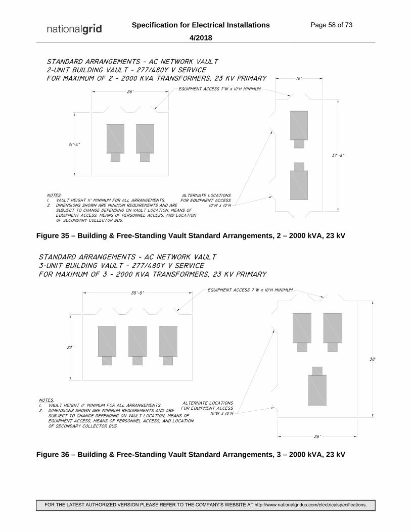
Specification for Electrical Installations Page 58 of 73
4/2018
FOR THE LATEST AUTHORIZED VERSION PLEASE REFER TO THE COMPANY’S WEBSITE AT http://www.nationalgridus.com/electricalspecifications.
Figure 35 – Building & Free-Standing Vault Standard Arrangements, 2 – 2000 kVA, 23 kV
Figure 36 – Building & Free-Standing Vault Standard Arrangements, 3 – 2000 kVA, 23 kV

Specification for Electrical Installations Page 59 of 73
4/2018
FOR THE LATEST AUTHORIZED VERSION PLEASE REFER TO THE COMPANY’S WEBSITE AT http://www.nationalgridus.com/electricalspecifications.
Figure 37 – Building & Free-Standing Vault Standard Arrangements, 4 – 2000 kVA, 23 kV
Figure 38 – Building & Free-Standing Vault Standard Arrangements, 2 – 2500 kVA, 23 kV

Specification for Electrical Installations Page 60 of 73
4/2018
FOR THE LATEST AUTHORIZED VERSION PLEASE REFER TO THE COMPANY’S WEBSITE AT http://www.nationalgridus.com/electricalspecifications.
Figure 39 – Building & Free-Standing Vault Standard Arrangements, 3 – 2500 kVA, 23 kV
Figure 40 – Building & Free-Standing Vault Standard Arrangements, 4 – 2500 kVA, 23 kV

Specification for Electrical Installations Page 61 of 73
4/2018
FOR THE LATEST AUTHORIZED VERSION PLEASE REFER TO THE COMPANY’S WEBSITE AT http://www.nationalgridus.com/electricalspecifications.
Figure 41 – Building & Free-Standing Vault Standard Arrangements, 2 – 1500 kVA, 34.5 kV
Figure 42 – Building & Free-Standing Vault Standard Arrangements, 3 – 1500 kVA, 34.5 kV

Specification for Electrical Installations Page 62 of 73
4/2018
FOR THE LATEST AUTHORIZED VERSION PLEASE REFER TO THE COMPANY’S WEBSITE AT http://www.nationalgridus.com/electricalspecifications.
Figure 43 – Building & Free-Standing Vault Standard Arrangements, 4 – 1500 kVA, 34.5 kV
Figure 44 – Building & Free-Standing Vault Standard Arrangements, 2 – 2000 kVA, 34.5 kV

Specification for Electrical Installations Page 63 of 73
4/2018
FOR THE LATEST AUTHORIZED VERSION PLEASE REFER TO THE COMPANY’S WEBSITE AT http://www.nationalgridus.com/electricalspecifications.
Figure 45 – Building & Free-Standing Vault Standard Arrangements, 3 – 2000 kVA, 34.5 kV
Figure 46 – Building & Free-Standing Vault Standard Arrangements, 4 – 2000 kVA, 34.5 kV

Specification for Electrical Installations Page 64 of 73
4/2018
FOR THE LATEST AUTHORIZED VERSION PLEASE REFER TO THE COMPANY’S WEBSITE AT http://www.nationalgridus.com/electricalspecifications.
Figure 47 – Building & Free-Standing Vault Standard Arrangements, 2 – 2500 kVA, 34.5 kV
Figure 48 – Building & Free-Standing Vault Standard Arrangements, 3 – 2500 kVA, 34.5 kV

Specification for Electrical Installations Page 65 of 73
4/2018
FOR THE LATEST AUTHORIZED VERSION PLEASE REFER TO THE COMPANY’S WEBSITE AT http://www.nationalgridus.com/electricalspecifications.
Figure 49 – Building & Free-Standing Vault Standard Arrangements, 4 – 2500 kVA, 34.5 kV
Figure 50 – Below-Grade Vault Located Outdoors Standard Layout

Specification for Electrical Installations Page 66 of 73
4/2018
FOR THE LATEST AUTHORIZED VERSION PLEASE REFER TO THE COMPANY’S WEBSITE AT http://www.nationalgridus.com/electricalspecifications.
1. Wall, Floor, and Roof Reinforcing Details:
Figure 51 – 6” Concrete Wall Minimum Standards
Figure 52 – 8” Concrete Wall Minimum Standards

Specification for Electrical Installations Page 67 of 73
4/2018
FOR THE LATEST AUTHORIZED VERSION PLEASE REFER TO THE COMPANY’S WEBSITE AT http://www.nationalgridus.com/electricalspecifications.
Figure 53 – CMU Wall Minimum Standards Plan View
Figure 54 – CMU Wall Minimum Standards Isometric View

Specification for Electrical Installations Page 68 of 73
4/2018
FOR THE LATEST AUTHORIZED VERSION PLEASE REFER TO THE COMPANY’S WEBSITE AT http://www.nationalgridus.com/electricalspecifications.
Figure 55 – Concrete Floor Minimum Standards
2. Company and NESC Structural Design Requirement: A. Strength Vaults shall be designed to sustain all expected loads that may be imposed upon the structure. The horizontal design loads, vertical design loads, or both shall consist of dead load, live load, equipment load, impact, load due to water table, frost, and any other load expected to be imposed upon the structure, to occur adjacent to the structure, or both. The structure shall sustain the combination of vertical and lateral loading that produces the maximum shear and bending moments in the structure. 1. For all below grade vaults, the live load shall consist of the weight of a moving tractor-semitrailer truck illustrated in the figure below. In the case of multilane pavements, the structure shall sustain the combination of loadings that results in vertical and lateral structure loadings that produce the maximum shear and bending moments in the structure. 2. Live loads shall be increased by 30% for impact.

Specification for Electrical Installations Page 69 of 73
4/2018
FOR THE LATEST AUTHORIZED VERSION PLEASE REFER TO THE COMPANY’S WEBSITE AT http://www.nationalgridus.com/electricalspecifications.
Figure 56 – Below Grade Vault Loading (Detail Common to NESC 2012 and AASHTO 2012)

Specification for Electrical Installations Page 70 of 73
4/2018
FOR THE LATEST AUTHORIZED VERSION PLEASE REFER TO THE COMPANY’S WEBSITE AT http://www.nationalgridus.com/electricalspecifications.

Specification for Electrical Installations Page 71 of 73
4/2018
FOR THE LATEST AUTHORIZED VERSION PLEASE REFER TO THE COMPANY’S WEBSITE AT http://www.nationalgridus.com/electricalspecifications.
Transformer Vaults
Spot Network Service
277/480V LVAC 3-phase 4-wire
Overall Ground Fault Protection System Interconnection Diagram
Ground Fault System - Control wire to trip Network Protector (NWP). 1 conduit per vault with 4 - #14 AWG copper wires of 4 different colors
Ground Fault System - CT secondary cable to relay. 1 for each bond conductor(s).
Customer supplied 120/208V 3-phase 30 amp circuit. 1 per vault.
1
4
3
2
Spare Control wire conduit; suggested.
1
2
3
To Network Transformer Neutral CT
To Customer’s Ground Fault Protection Cabinet
Current Transformer Control Cabinet “CC2”in Network Transformer Vault
(internal wiring)
From Customer’s Ground Fault Protection Cabinet
86/LO (Trip NWP)
86/LO (Trip HSSI)
To NWP - 86/LO (Trip NWP)
To NMVI - 86/LO (Trip HSSI)
From Customer’s Service Panel 30 amp 208/120V 3-phase 5 wire Circuit
(1 Green, 1 White, 3 Black)
To F
ire Pum
p (If E
quipped)
Fire Pump – Service Equipment (If Euipped)
A
NCB
GFI
Fire Pump – CT Cabinet (If Equipped)
Main Service Equipment
120/208V3-phaseService Panel
Utility Billing Meter
Customer’s Ground Fault
Protection Cabinet
1
2
3
Utility Billing Meter
5 Customer-owned Secondary Service Conduit(s) for Customer-owned Service Cable
HSS
NC
SC
LB
Company-owned Primary Protective Device – High-side Switch Interrupter (If Equipped)
Company-owned Primary Protective Device – High-side Switch Control (If Equipped)
Company-owned Primary Protective Device – High-side Switch Network Controller (If Equipped)
Company-owned Secondary Disconnect Device (a.k.a. Link Box) (If Equipped)
10A
15A
15A
To Vault Lighting Circuit(1 White, 1 Black)
To Vault Sump Pump Controller & Sensor(1 Green, 1 White, 1 Black)
To Vault General Purpose Receptacle(1 Green, 1 White, 1 Black)
White
Green
Network Transformer
Neutral CT Circuit
To NMVI Network Controller(1 Green, 1 White, 1 Black)
If power is not provided from General Network
Electric Room
6
Customer supplied 120/208V source for Ground Fault Protection Scheme.
6
Please note that the network transformer must have insulated neutral, that the customer switchgear neutral must be insulated, and that each bond from neutral to ground must have a CT included in the GFI System.
Equipment ground for conduit, cabinet, cable tray, and/or switchgear
Company-owned Secondary Service Cables
Customer-owned CT for Ground Fault Protection System
Power Box {“AP”}in Network Transformer Vault
(internal wiring)
L1
C2
T1
Ground Fault Protection Control Cabinet “CC3”in Network Transformer Vault
(internal wiring)
N03001N02002N01003 HSSI NC SCHSSI NC SC HSSI NC SC
LB LB LB
1 - 4/0 AWG Copper 600V1 - 4/0 AWG Copper 600V1 - 4/0 AWG Copper 600V
AP
CC
2
CC
2
1 2 3 4 5
AP
AP
CC
2C
C3
CC
3
CC
3
Customer-owned Secondary Service Cables
Figure 57 – Ground Fault Protection Interconnection Example

Specification for Electrical Installations Page 72 of 73
4/2018
FOR THE LATEST AUTHORIZED VERSION PLEASE REFER TO THE COMPANY’S WEBSITE AT http://www.nationalgridus.com/electricalspecifications.
Control Cabinet{“CC2 – N02002”}
Control Cabinet{“CC2 – N01003”}
Spot Network Service
277/480V LVAC3-phase 4-wire
Ground Fault System DesignCT & Relay circuitry
Control Drawing (page 1 of 2)
MTC
L1T1C2
MTC
L1T1C2
MTC
L1T1C2
3
4
2
1
86-GFSLO
1
C1
6
52
C2
8
73
C3
10
9
86LO
86LO
86LO
86LO
86LO
86LO
TD86
TD86
TD86
TD86
TD86
7
9
To
ene
rgiz
e 94
rel
ay (
GE
T
ype
HG
A)
Trip
NW
P &
Blo
ck
Rec
lose
of N
0100
3 N
WP
To
ene
rgiz
e 94
rel
ay (
GE
T
ype
HG
A)
Trip
NW
P &
Blo
ck
Rec
lose
of N
0200
2 N
WP
To
ene
rgiz
e 94
rel
ay (
GE
T
ype
HG
A)
Trip
NW
P &
Blo
ck
Rec
lose
of N
0300
1 N
WP
4
C4
12
116
C6
16
155
C5
14
13
2 1
4 3
TD
CT
Tes
tC
S
1T 1
6 5
10 9
8 7
12 11
12 11
12 11
12 11
10 9
10 9
10 9
2T 2
3T 3
3T 3
3T 3
3T 3To Customer’s Fire Pump
Service Equipment Bond Conductor
To Customer’s Main Service Equipment Bond Conductor
To Customer’s Main Service Equipment Bond Conductor
To
Trip
HS
SI R
0100
3(N
o B
lock
Rec
lose
ca
pabi
lity)
To
Trip
HS
SI R
0200
2(N
o B
lock
Rec
lose
ca
pabi
lity)
To
Trip
HS
SI R
0300
1(N
o B
lock
Rec
lose
ca
pabi
lity)
N01003
N02002
N03001
TD86
TD86
TD86
RPB
TPB
= Reset “Ground Break” System pushbutton
= Test “Ground Break” System pushbutton
= CT Test Device
= “Ground Break” System Test Control Switch
TDCT
TestCS
= “Ground Break” System Lockout Relay86LO
TD86
= “86-GFS” Relay Test Control Switch
Control Cabinet{“CC2 – N03001”}
86LO
7
C7
18
17
To
Cu
stom
er’s
Ala
rm C
ircu
it(s
ugge
sted
)
TD86
Customer’s Ground Fault Protection Cabinet
To Power Source
Test Block & Switch
2
2
2
GE “Ground Break” SystemMonitor Panel Model TGSMP with Indicator Light
OrEaton GFR System
OrABB GRC System
Or Equivalent
Lock-out Relay
Test Block
Note(s):1. Customer furnishes, installs, owns, & maintains wire from Customer’s Ground Fault Protection Cabinetto Company-owned Control Cabinet
Figure 58 – Ground Fault Protection Control System Example Sheet 1

Specification for Electrical Installations Page 73 of 73
4/2018
FOR THE LATEST AUTHORIZED VERSION PLEASE REFER TO THE COMPANY’S WEBSITE AT http://www.nationalgridus.com/electricalspecifications.
Control Cabinet{“CC3 – N03001”}
Control Cabinet{“CC3 – N02002”}
Control Cabinet{“CC3 – N01003”}
3
7
1
4
8
2
Trip Open NWP
Block Reclose of NWP
Spare
Spare
3
7
1
4
8
2
Trip Open NWP
Block Reclose of NWP
Spare
Spare
3
7
1
4
8
2
Trip Open NWP
Block Reclose of NWP
Spare
Spare
6
594GFS
6
594GFS
6
594GFS
HSSI - Network
Controller
HSSI - Network
Controller
HSSI - Network
Controller
N01003
N02002
N03001
R01003
R02002
R03001
Network Protector
Network Protector
Network Protector
4
3
2
1
J5
86-GFSLO
6
C6
16
15
86LO
TD86
5
C5
14
13
86LO
TD86
4
C4
12
11
86LO
TD86
3
C3
10
9
86LO
TD86
2
C2
8
7
86LO
TD86
1
C1
6
5
86LO
TD86
Customer’s Ground Fault Protection Cabinet
7
C7
18
17
86LO
TD86
To Customer’s Alarm Circuit(suggested)
3
3
3
4
3
2
1
J5
4
3
2
1
J5
Spot Network Service
277/480V LVAC3-phase 4-wire
Ground Fault System DesignTrip Circuitry
Control Drawing (page 2 of 2)
Note(s):
1. Customer furnishes, installs, owns, & maintains wire & conduit from Customer’s Ground Fault Protection Cabinet to Company-owned Control Cabinet except for install work within vault.
2. The 86-GPS/LO contacts & Test Device shall be rated greater than 277 volts.
Customer’s-owned Vaults with Company-owned Equipment
Figure 59 – Ground Fault Protection Control System Example Sheet 2