Embed Size (px)
Citation preview

TESLA INSTITUTETESLA INSTITUTE
TransformerTransformer
Factory TestsFactory Tests
TESLA INSTITUTE Transformer Factory Tests
www.tesla-institute.com 2
TESLA INSTITUTE Transformer Factory Tests
Like TESLA INSTITUTE Page !
www.tesla-institute.com 3

TESLA INSTITUTE Transformer Factory Tests
Subscribe our Youtube channel !
Learn more withYoung English Engineer
www.tesla-institute.com 4
TESLA INSTITUTE Transformer Factory Tests
ContentsContents...............................................................................................5
Factory tests..........................................................................................7
No-load losses and currents.....................................................................8
No-Load Excitation Current....................................................................11
Measurement of impedance voltage and load loss......................................12
Purpose of the measurement...............................................................13
Apparatus and measuring circuit..........................................................13
Performance of the measurement........................................................14
Results............................................................................................15
Dielectric (Insulation) Test.....................................................................21
Insulation tests to be performed..........................................................21
Switching impulse test....................................................................21
Lightning impulse test.....................................................................22
Separate source AC withstand voltage test.........................................22
Induced AC voltage test (short duration ACSD and long duration ACLD). 22
Partial discharge measurement........................................................22
Repeating the dielectric tests..............................................................23
Switching Impulse Test..........................................................................25
Purpose of the Test............................................................................25
Lightning Impulse Test..........................................................................29
Partial Discharge Test............................................................................31
How Partial-Discharge occurs and measured magnitudes?.......................32
Measuring circuit and application.........................................................33
Application of the test........................................................................35
Voltage level.....................................................................................35
www.tesla-institute.com 5
TESLA INSTITUTE Transformer Factory Tests
Evaluation........................................................................................36
Insulation Power Factor.........................................................................37
Insulation Resistance............................................................................38
Important Notes................................................................................39
Insulation Resistance Test Procedure....................................................40
Noise Measurement..............................................................................42
Where all this noise is coming from?....................................................44
Vibroacoustic energy sources in the power transformers..........................46
Matters of design...............................................................................46
Sound ways of seeing........................................................................47
On-site solutions...............................................................................48
Need for Research and Development....................................................49
Temperature Rise (Heat Run).................................................................50
Short-Circuit Test..................................................................................51
www.tesla-institute.com 6
TESLA INSTITUTE Transformer Factory Tests
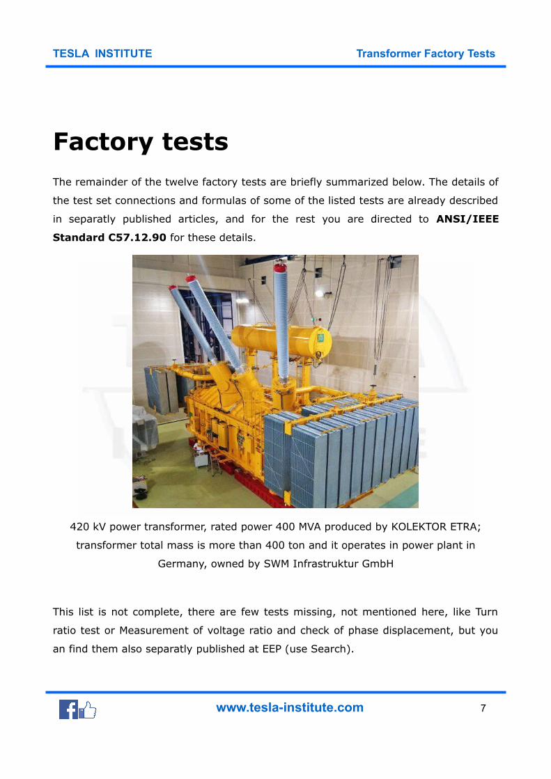
Factory testsThe remainder of the twelve factory tests are briefly summarized below. The details of
the test set connections and formulas of some of the listed tests are already described
in separatly published articles, and for the rest you are directed to ANSI/IEEE
Standard C57.12.90 for these details.
420 kV power transformer, rated power 400 MVA produced by KOLEKTOR ETRA;
transformer total mass is more than 400 ton and it operates in power plant in
Germany, owned by SWM Infrastruktur GmbH
This list is not complete, there are few tests missing, not mentioned here, like Turn
ratio test or Measurement of voltage ratio and check of phase displacement, but you
an find them also separatly published at EEP (use Search).
www.tesla-institute.com 7
TESLA INSTITUTE Transformer Factory Tests
No-load losses and currents
The no-load losses of a transformer are grouped in three main topics:
1. Iron losses at the core of the transformer,
2. Dielectric losses at the insulating material and
3. The Copper losses due to no-load current.
The last two of them are very small in value and can be ignored.
So, only the iron losses are considered in determining the no-load losses.
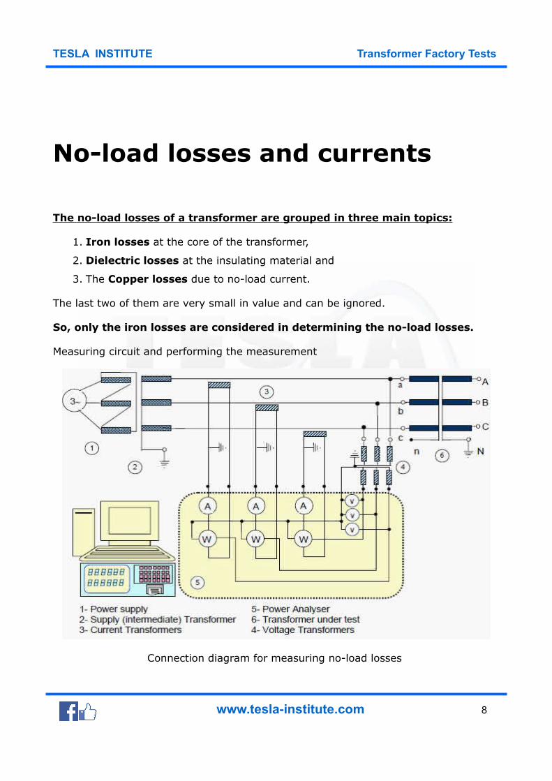
Measuring circuit and performing the measurement
Connection diagram for measuring no-load losses
www.tesla-institute.com 8
TESLA INSTITUTE Transformer Factory Tests
In general according to the standards, if there is less than 3% difference between the
effective (U) value and the average (U’) value of the supply voltage, the shape
of the wave is considered as appropriate for measurements.
If the supply voltage is different than sinusoid, the measured no-load losses have to
be corrected by a calculation. In this case, the effective (r.m.s.) value and the
average (mean) value of the voltage are different. If the readings of both
voltmeter are equal, there is no need for correction.
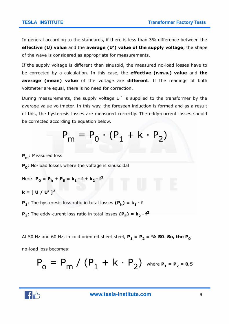
During measurements, the supply voltage U´ is supplied to the transformer by the
average value voltmeter. In this way, the foreseen induction is formed and as a result
of this, the hysteresis losses are measured correctly. The eddy-current losses should
be corrected according to equation below.
Pm = P0 · (P1 + k · P2)
Pm: Measured loss
P0: No-load losses where the voltage is sinusoidal
Here: P0 = Ph + PE = k1 · f + k2 · f2
k = [ U / U’ ]2
P1: The hysteresis loss ratio in total losses (Ph) = k1 · f
P2: The eddy-curent loss ratio in total losses (PE) = k2 · f2
At 50 Hz and 60 Hz, in cold oriented sheet steel, P1 = P2 = % 50. So, the P0
no-load loss becomes:
Po = Pm / (P1 + k · P2) where P1 = P2 = 0,5
www.tesla-institute.com 9
TESLA INSTITUTE Transformer Factory Tests
According to IEC 60076-1: Pm = P0 · (1 + d) where d = [ (U’ – U) / U’ ]
During no-load loss measurement, the effective value of the no-load current of the
transformer is measured as well. In general, in three phase transformers, evaluation
is made according to the average of the three phase currents.
Before the no-load measurements, the transformer might have been magnetised by
direct current and it’s components (resistance measurement or impulse tests).
For this reason, the core has to be demagnetised. To do this, it has to be supplied by
a voltage value (increasing and decreasing between the maximum and minimum
voltage values for a few minutes) higher than the rated voltage for a certain time and
then the measurements can be made.
The no-load currents are neither symmetrical nor of equal amplitude in three phase
transformers. The phase angles between voltages and currents may be different for
each of three phases.
For this reason, the wattmeter readings on each of the three phases may not
be equal. Sometimes one of the wattmeter values can be 0 (zero) or negative (-).
www.tesla-institute.com 10
TESLA INSTITUTE Transformer Factory Tests
No-Load Excitation Current
This current is measured in the winding used to excite the transformer with the
other windings open-circuited. It is generally expressed in percent of the rated
current of the winding. No-load excitation current is not sinusoidal and contains, as we
have seen, odd harmonics (predominantly third harmonic current).
The ammeter used to record the no-load excitation current is an RMS meter which
reads the square root of the sum of the squares of the harmonic currents.
www.tesla-institute.com 11
TESLA INSTITUTE Transformer Factory Tests
Measurement of impedance
voltage and load loss
The transformer must be in a specific state before the load losses and impedance
voltage are measured. The temperature of the insulating liquid must be stabilized and
the difference between the top and bottom oil temperatures shall be less than 5°C.
The winding temperatures must be measured (using a resistance method) before and
after the test and the average taken as the true temperature. The difference in
the winding temperature before and after the test must not exceed 5°C.
The two test methods for measuring load losses and impedance voltage are:
1. Wattmeter-voltmeter-ammeter method and
2. Impedance bridge method.
Circuit for the impedance and load-loss measurement
These tests generally apply a reduced voltage to one set of windings with the other
set of windings short-circuited. For three-winding transformers, these tests are
repeated for each combination of windings taken two at a time.
www.tesla-institute.com 12
TESLA INSTITUTE Transformer Factory Tests
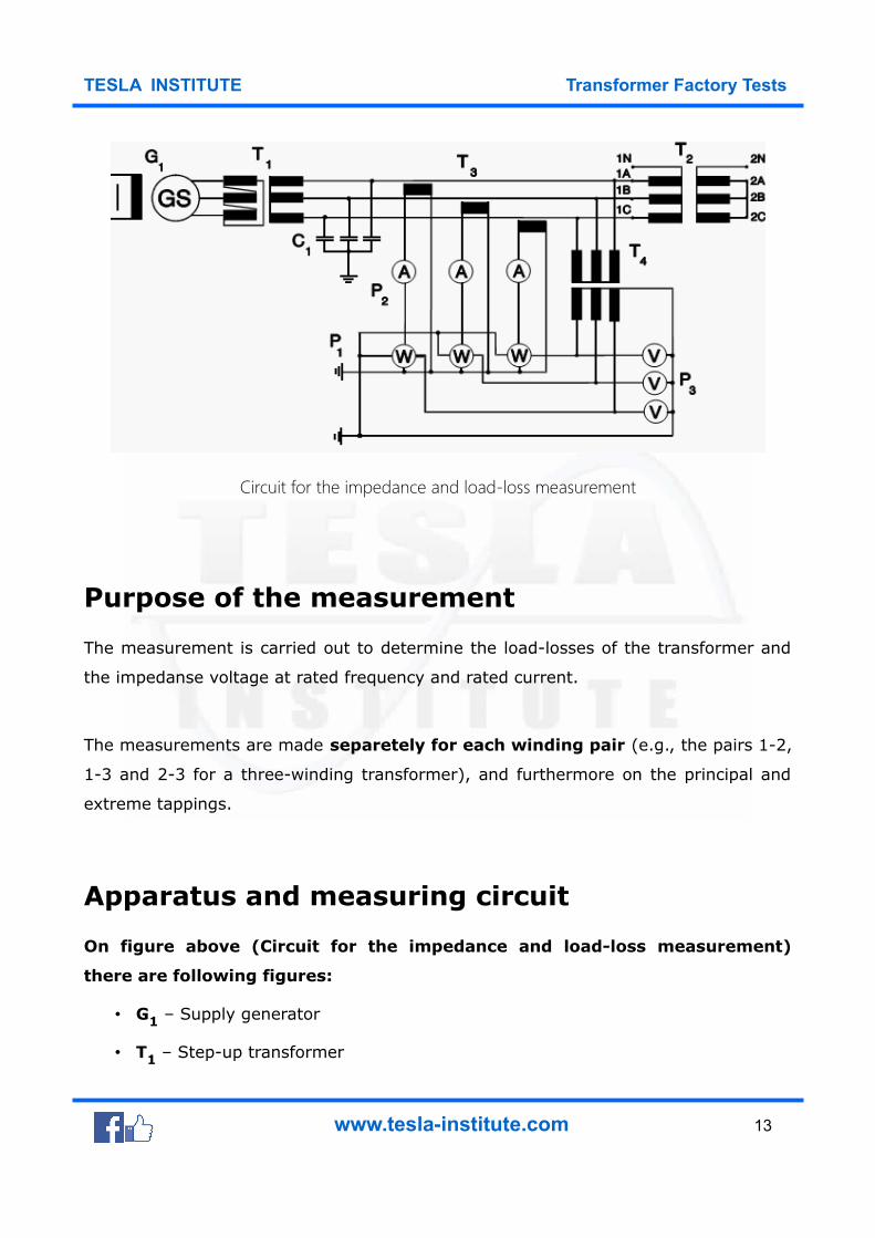
Circuit for the impedance and load-loss measurement
Purpose of the measurement
The measurement is carried out to determine the load-losses of the transformer and
the impedanse voltage at rated frequency and rated current.
The measurements are made separetely for each winding pair (e.g., the pairs 1-2,
1-3 and 2-3 for a three-winding transformer), and furthermore on the principal and
extreme tappings.
Apparatus and measuring circuit
On figure above (Circuit for the impedance and load-loss measurement)
there are following figures:
• G1 – Supply generator
• T1 – Step-up transformer
www.tesla-institute.com 13
TESLA INSTITUTE Transformer Factory Tests
• T2 – Transformer to be tested
• T3 – Current transformers
• T4 – Voltage transformers
• P1 – Wattmeters
• P2 – Ammeters (r.m.s. value)
• P3 – Voltmeters (r.m.s. value)
• C1 – Capacitor bank
The supply and measuring facilities are not described here. Current is generally
supplied to the h.v. winding and the l.v. winding is short-circuited.
Performance of the measurement
If the reactive power supplied by the generator G1 is not sufficient when measuring
large transformers, a capacitor bank C1 is used to compensate part of the inductive
reactive power taken by the transformer T2.The voltage of the supply generator is
raised until the current has attained the required value (25…100 % of the rated
current).
In order to increase the accuracy of readings will be taken at several current values
near the required level. If a winding in the pair to be measured is equipped with an
off-circuit or on-load tap-changer. the measurements are carried out on the principal
and extreme tappings.
The readings have to be taken as quickly as possible, because the windings tend to
warm up due to the current and the loss values obtained in the measurement are
accondingly too high.
It the transformer has more than two windings all winding pairs are
measured separately.
www.tesla-institute.com 14
TESLA INSTITUTE Transformer Factory Tests
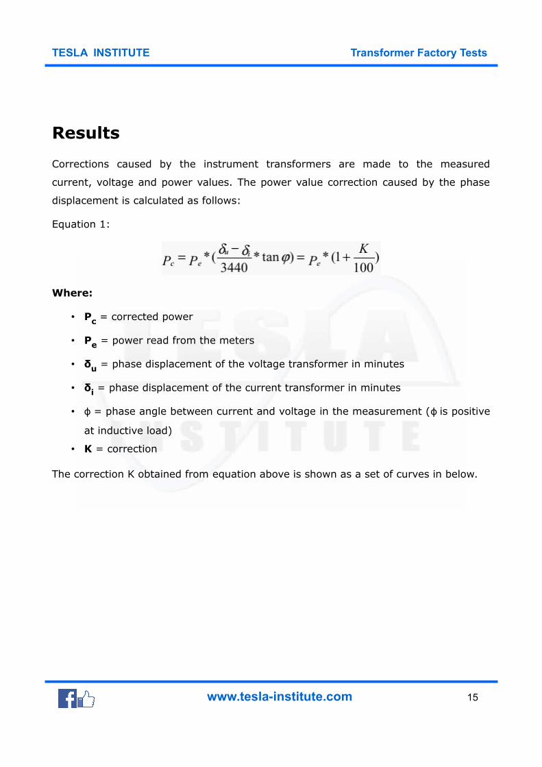
Results
Corrections caused by the instrument transformers are made to the measured
current, voltage and power values. The power value correction caused by the phase
displacement is calculated as follows:
Equation 1:
Where:
• Pc = corrected power
• Pe = power read from the meters
• δu = phase displacement of the voltage transformer in minutes
• δi = phase displacement of the current transformer in minutes
• ϕ = phase angle between current and voltage in the measurement ( is positiveϕ
at inductive load)
• K = correction
The correction K obtained from equation above is shown as a set of curves in below.
www.tesla-institute.com 15
TESLA INSTITUTE Transformer Factory Tests
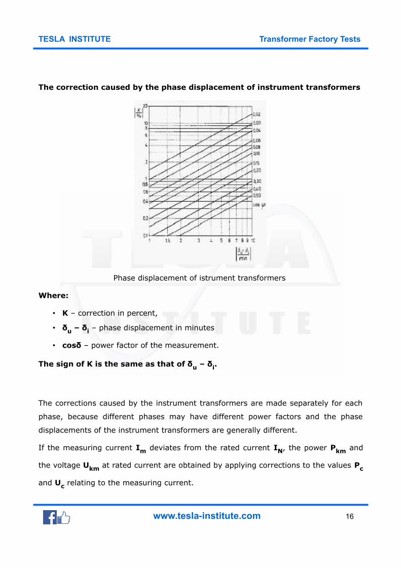
The correction caused by the phase displacement of instrument transformers
Phase displacement of istrument transformers
Where:
• K – correction in percent,
• δu – δi – phase displacement in minutes
• cosδ – power factor of the measurement.
The sign of K is the same as that of δu – δi.
The corrections caused by the instrument transformers are made separately for each
phase, because different phases may have different power factors and the phase
displacements of the instrument transformers are generally different.
If the measuring current Im deviates from the rated current IN, the power Pkm and
the voltage Ukm at rated current are obtained by applying corrections to the values Pc
and Uc relating to the measuring current.
www.tesla-institute.com 16
TESLA INSTITUTE Transformer Factory Tests
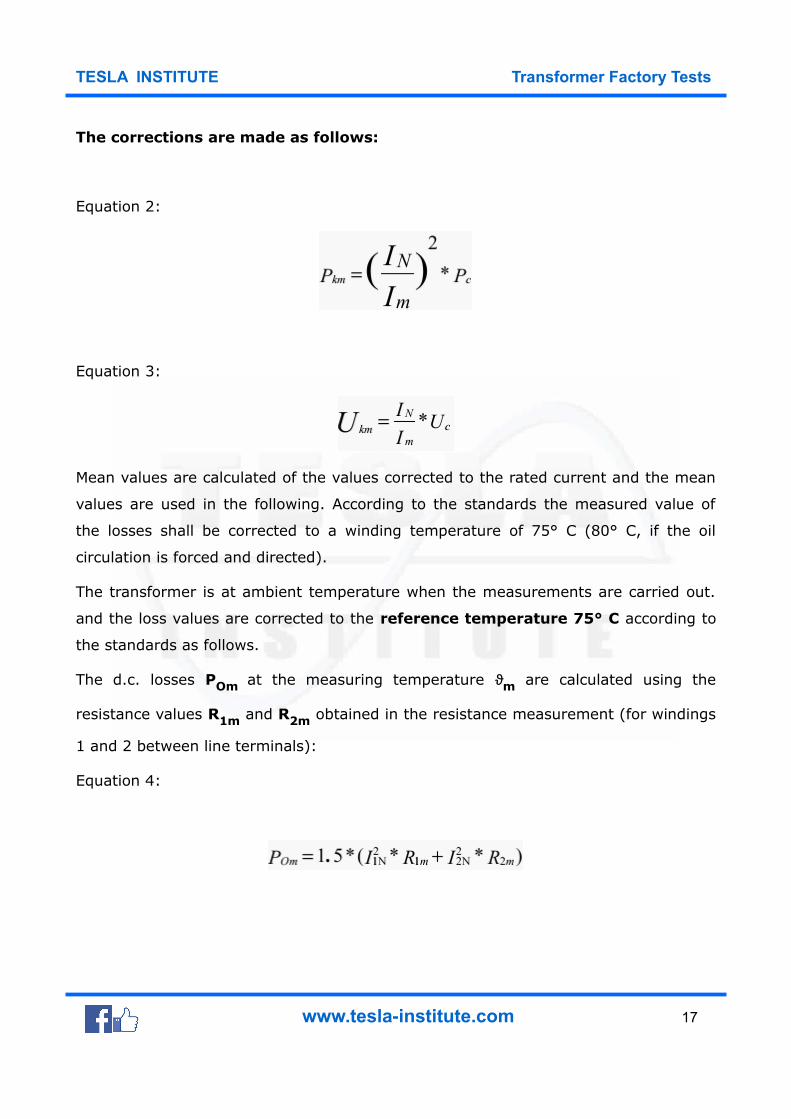
The corrections are made as follows:
Equation 2:
Equation 3:
Mean values are calculated of the values corrected to the rated current and the mean
values are used in the following. According to the standards the measured value of
the losses shall be corrected to a winding temperature of 75° C (80° C, if the oil
circulation is forced and directed).
The transformer is at ambient temperature when the measurements are carried out.
and the loss values are corrected to the reference temperature 75° C according to
the standards as follows.
The d.c. losses POm at the measuring temperature ϑm are calculated using the
resistance values R1m and R2m obtained in the resistance measurement (for windings
1 and 2 between line terminals):
Equation 4:
www.tesla-institute.com 17
TESLA INSTITUTE Transformer Factory Tests
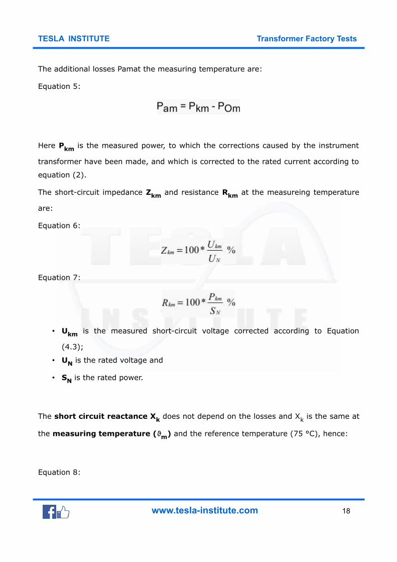
The additional losses Pamat the measuring temperature are:
Equation 5:
Here Pkm is the measured power, to which the corrections caused by the instrument
transformer have been made, and which is corrected to the rated current according to
equation (2).
The short-circuit impedance Zkm and resistance Rkm at the measureing temperature
are:
Equation 6:
Equation 7:
• Ukm is the measured short-circuit voltage corrected according to Equation
(4.3);
• UN is the rated voltage and
• SN is the rated power.
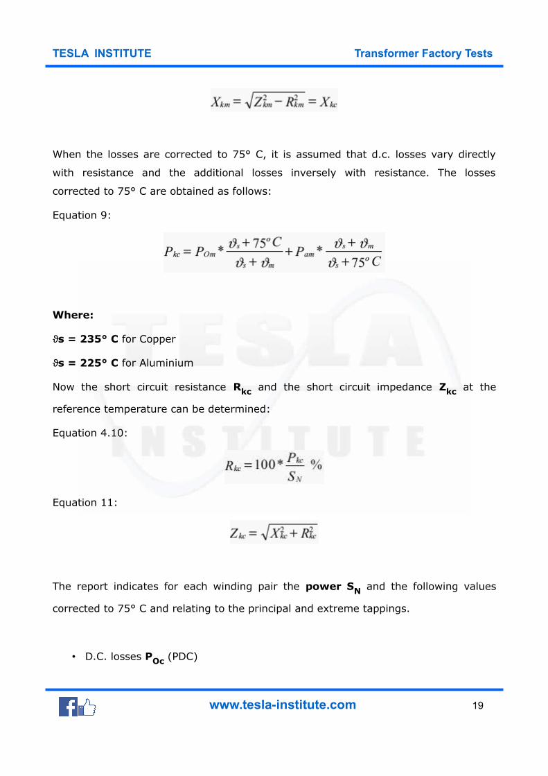
The short circuit reactance Xk does not depend on the losses and Xk is the same at
the measuring temperature (ϑm) and the reference temperature (75 °C), hence:
Equation 8:
www.tesla-institute.com 18
TESLA INSTITUTE Transformer Factory Tests
When the losses are corrected to 75° C, it is assumed that d.c. losses vary directly
with resistance and the additional losses inversely with resistance. The losses
corrected to 75° C are obtained as follows:
Equation 9:
Where:
s = 235° Cϑ for Copper
s = 225° Cϑ for Aluminium
Now the short circuit resistance Rkc and the short circuit impedance Zkc at the
reference temperature can be determined:
Equation 4.10:
Equation 11:
The report indicates for each winding pair the power SN and the following values
corrected to 75° C and relating to the principal and extreme tappings.
• D.C. losses POc (PDC)
www.tesla-institute.com 19
TESLA INSTITUTE Transformer Factory Tests
• Additional losses Pac (PA)
• Load losses Pkc (PK)
• Short circuit resistance Rkc (RK)
• Short circuit reaactance Xkc (XK)
• Short circuit impedance Zkc (ZK)
www.tesla-institute.com 20
TESLA INSTITUTE Transformer Factory Tests
Dielectric (Insulation) Test
These tests consist of applied-voltage tests and induced-voltage tests.
Applied-voltage tests apply a high voltage to all bushings of a winding, one winding
at a time, with the other windings grounded. A 60 Hz voltage is increased gradually
over 15 s and held for 40 s and reduced to zero over 5 s.
Induced-voltage tests apply a high voltage across a winding with the other
windings open-circuited in order to test the quality of the turn-to-turn insulation. In
order to prevent core saturation at the higher excitation voltage, the frequency of the
induced-voltage test is increased (typically around 120 Hz). The induced voltage is
applied for 7200 cycles or 60 s, whichever is shorter.
Insulation tests to be performed
The following insulation tests are performed in order to meet the transformer
insulation strength expectations. Unless otherwise requested by the customer, the
following test are performed in the following order (IEC 60076-3) :
Switching impulse test
To confirm the insulation of the transformer terminals and windings to the earthed
parts and other windings, and to confirm the insulation strength in the windings and
through the windings.
www.tesla-institute.com 21
TESLA INSTITUTE Transformer Factory Tests
Lightning impulse test
to confirm the transformer insulation strength in case of a lightning hitting the
connection terminals.
Separate source AC withstand voltage test
To confirm the insulation strength of the transformer line and neutral connection
terminals and the connected windings to the earthed parts and other windings.
Induced AC voltage test (short duration ACSD and
long duration ACLD)
To confirm the insulation strength of the transformer connection terminals and the
connected windings to the earthed parts and other windings, both between the phases
and through the winding.
Partial discharge measurement
To confirm the “partial dicharge below a determined level” property of the
transformer insulationstructure under operating conditions.
According to standards, the transformer windings are made to meet the maximum operating voltage Um and the related insulation levels.
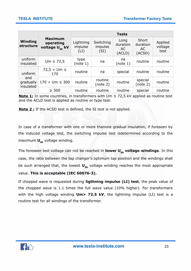
The transformer insulation levels and the insulation test to be applied according to
IEC 60076-3 is shown in the below table.
www.tesla-institute.com 22
TESLA INSTITUTE Transformer Factory Tests
Windingstructure
Maximumoperating
voltage Um kV
Tests
Lightningimpulse
(LI)
Switchingimpulse
(SI)
Longduration
AC(ACLD)
Shortduration
AC(ACSD)
Appliedvoltage
test
uniforminsulated
Um ≤ 72,5type
(note 1)na
na(note 1)
routine routine
uniformand
graduallyinsulated
72,5 < Um ≤170
routine na special routine routine
170 < Um ≤ 300 routineroutine(note 2)
routinespecial
(note 2)routine
≥ 300 routine routine routine special routine
Note 1: In some countries, in transformers with Um ≤ 72,5 kV applied as routine testand the ACLD test is applied as routine or type test.
Note 2 : If the ACSD test is defined, the SI test is not applied.
In case of a transformer with one or more thanone gradual insulation, if foreseen by
the induced voltage test, the switching impulse test isdetermined according to the
maximum Um voltage winding.
The foreseen test voltage can not be reached in lower Um voltage windings. In this
case, the ratio between the tap changer’s optimum tap position and the windings shall
be such arranged that, the lowest Um voltage winding reaches the most appropriate
value. This is acceptable (IEC 60076-3).
If chopped wave is requested during ligthning impulse (LI) test, the peak value of
the chopped wave is 1.1 times the full wave value (10% higher). For transformers
with the high voltage winding Um> 72.5 kV, the lightning impulse (LI) test is a
routine test for all windings of the transformer.
www.tesla-institute.com 23
TESLA INSTITUTE Transformer Factory Tests
Repeating the dielectric tests
If no modification is made in the internal insulation of a transformer, only maintenance
is made, or if insulation tests are required for a transformer which is in operation, and
if no agreement is made with the customer, test is performed with test voltages at
80% of the original test values. However, the long duration induced voltage test
(ACLD) is always repeated with 100% of the original value.
www.tesla-institute.com 24
TESLA INSTITUTE Transformer Factory Tests
Switching Impulse Test
Purpose of the Test
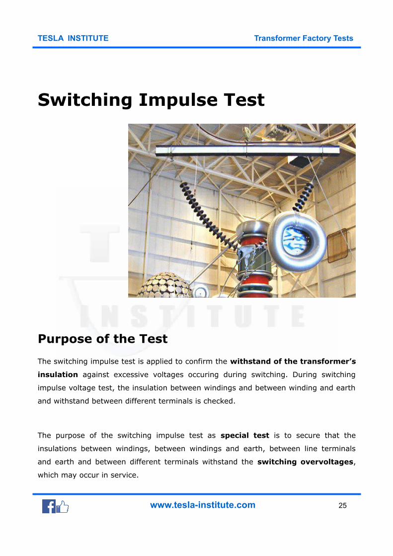
The switching impulse test is applied to confirm the withstand of the transformer’s
insulation against excessive voltages occuring during switching. During switching
impulse voltage test, the insulation between windings and between winding and earth
and withstand between different terminals is checked.
The purpose of the switching impulse test as special test is to secure that the
insulations between windings, between windings and earth, between line terminals
and earth and between different terminals withstand the switching overvoltages,
which may occur in service.
www.tesla-institute.com 25
TESLA INSTITUTE Transformer Factory Tests
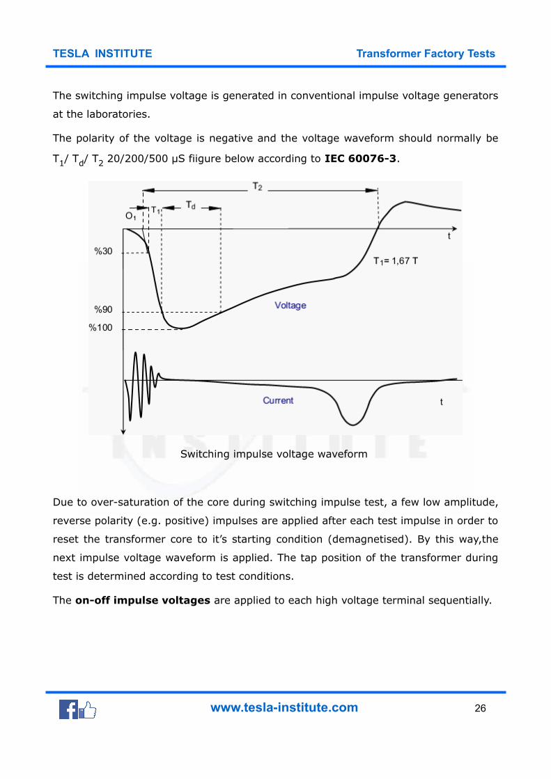
The switching impulse voltage is generated in conventional impulse voltage generators
at the laboratories.
The polarity of the voltage is negative and the voltage waveform should normally be
T1/ Td/ T2 20/200/500 μS fiigure below according to IEC 60076-3.
Switching impulse voltage waveform
Due to over-saturation of the core during switching impulse test, a few low amplitude,
reverse polarity (e.g. positive) impulses are applied after each test impulse in order to
reset the transformer core to it’s starting condition (demagnetised). By this way,the
next impulse voltage waveform is applied. The tap position of the transformer during
test is determined according to test conditions.
The on-off impulse voltages are applied to each high voltage terminal sequentially.
www.tesla-institute.com 26
TESLA INSTITUTE Transformer Factory Tests
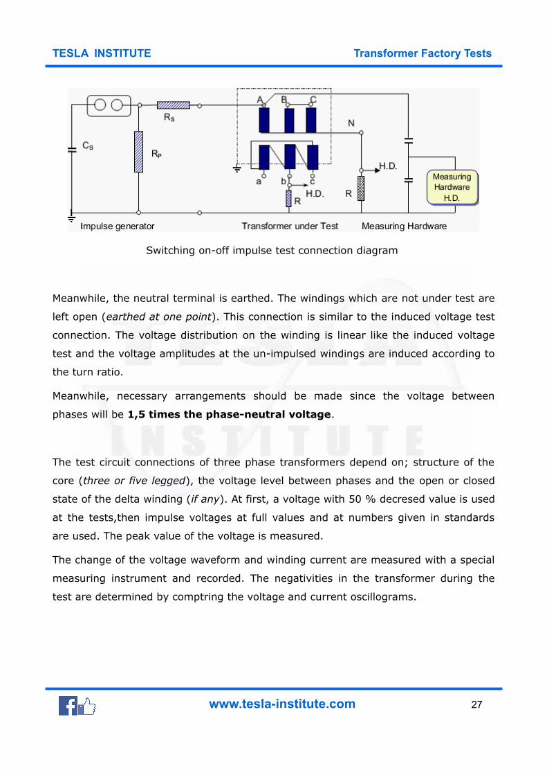
Switching on-off impulse test connection diagram
Meanwhile, the neutral terminal is earthed. The windings which are not under test are
left open (earthed at one point). This connection is similar to the induced voltage test
connection. The voltage distribution on the winding is linear like the induced voltage
test and the voltage amplitudes at the un-impulsed windings are induced according to
the turn ratio.
Meanwhile, necessary arrangements should be made since the voltage between
phases will be 1,5 times the phase-neutral voltage.
The test circuit connections of three phase transformers depend on; structure of the
core (three or five legged), the voltage level between phases and the open or closed
state of the delta winding (if any). At first, a voltage with 50 % decresed value is used
at the tests,then impulse voltages at full values and at numbers given in standards
are used. The peak value of the voltage is measured.
The change of the voltage waveform and winding current are measured with a special
measuring instrument and recorded. The negativities in the transformer during the
test are determined by comptring the voltage and current oscillograms.
www.tesla-institute.com 27
TESLA INSTITUTE Transformer Factory Tests
The sudden collapses of the voltage (surges) and abnormal sounds show deformation
of the insulation in the transfomer. The deformation of the voltage waveform and
increase in noise due to magnetic saturation of the core should not be considered as
fault.
The test voltage values, impulse shapes, and number of impulses at different voltage
levels must be stated in the report.
Switching Impulse Voltage Waveform :
Front : T1 ≥100 µS = 1,67 T
90% value : Td ≥ 200 µS
Time for cutting the axis : T2 ≥ 500 µS
www.tesla-institute.com 28
TESLA INSTITUTE Transformer Factory Tests
Lightning Impulse Test
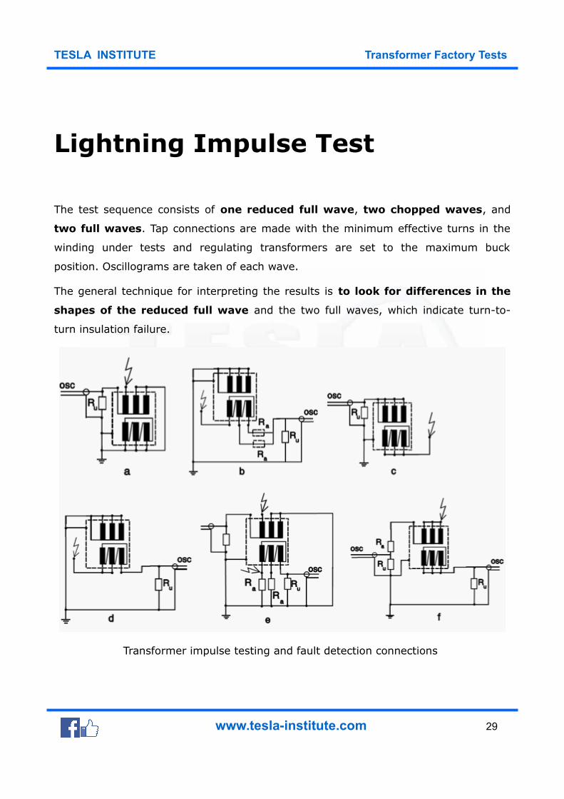
The test sequence consists of one reduced full wave, two chopped waves, and
two full waves. Tap connections are made with the minimum effective turns in the
winding under tests and regulating transformers are set to the maximum buck
position. Oscillograms are taken of each wave.
The general technique for interpreting the results is to look for differences in the
shapes of the reduced full wave and the two full waves, which indicate turn-to-
turn insulation failure.
Transformer impulse testing and fault detection connections
www.tesla-institute.com 29
TESLA INSTITUTE Transformer Factory Tests
Additional test criteria are found in IEEE Std. C57.98-1993. The impulse tests
probably have the highest likelihood failures among all of the factory tests that are
typically performed.
www.tesla-institute.com 30

TESLA INSTITUTE Transformer Factory Tests
Partial Discharge Test
This routine test aims to measure the partial discharges which may occur in the
transformer insulation structure during test.
Partial-discharges are electrical arks which form the surges between electrodes of any
area of the insulating media of a transformer between the conductors. These
discharges may occur in air bubbles left in the insulating media, gaps in the solid
materials or at the surfaces of two different insulators.
Although these discharges have small (weak) energy, the thermal energies due to
these discharges can cause aging, deformation and tear of the insulating
material.
www.tesla-institute.com 31
TESLA INSTITUTE Transformer Factory Tests
The following conditions can be determined during partial-discharge
measurement:
1. To determine whether a partial-discharge above a certain value has occurred in
the transformer at a pre-defined voltage.
2. To define the voltage values where the partial-discharge starts by increasing the
applied voltage (partial-discharge start voltage) and the value where the
partial-discharge ceases by decreasing the applied voltage (partial-discharge
cease voltage).
3. To define the partial-discharge strength at a pre-defined voltage.
How Partial-Discharge occurs and
measured magnitudes?
The structure where a partial-discharge occurred in an insulating media is shown in
the simplified figure below. As seen on the simpliified diagram, the impulses forming
on the discharge point cause a ΔU voltage drop at the transformer line
terminals. This forms a measurable “q” load at the measuring impedance.
This load is called apparent load and given in pC (Pico-Coulomb) units.
During measurements: ΔU voltage drop, average value of apparent partial-
discharge current, partial- discharge power, impulse count within a time unit, partial-
discharge start and cease voltages can also be determined.
www.tesla-institute.com 32
TESLA INSTITUTE Transformer Factory Tests
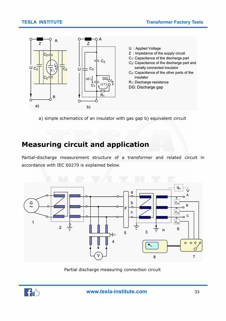
a) simple schematics of an insulator with gas gap b) equivalent circuit
Measuring circuit and application
Partial-discharge measurement structure of a transformer and related circuit in
accordance with IEC 60270 is explained below.
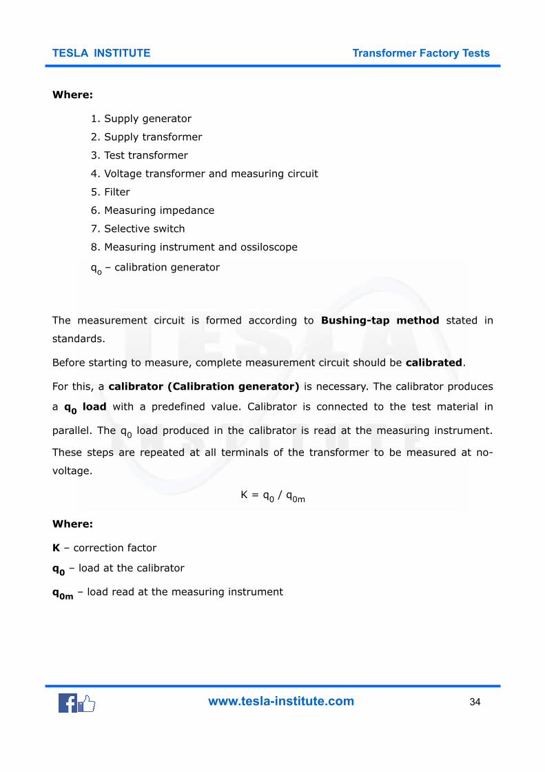
Partial discharge measuring connection circuit
www.tesla-institute.com 33
TESLA INSTITUTE Transformer Factory Tests
Where:
1. Supply generator
2. Supply transformer
3. Test transformer
4. Voltage transformer and measuring circuit
5. Filter
6. Measuring impedance
7. Selective switch
8. Measuring instrument and ossiloscope
qo – calibration generator
The measurement circuit is formed according to Bushing-tap method stated in
standards.
Before starting to measure, complete measurement circuit should be calibrated.
For this, a calibrator (Calibration generator) is necessary. The calibrator produces
a q0 load with a predefined value. Calibrator is connected to the test material in
parallel. The q0 load produced in the calibrator is read at the measuring instrument.
These steps are repeated at all terminals of the transformer to be measured at no-
voltage.
K = q0 / q0m
Where:
K – correction factor
q0 – load at the calibrator
q0m – load read at the measuring instrument
www.tesla-institute.com 34
TESLA INSTITUTE Transformer Factory Tests
Application of the test
After the calibration operations are completed, the calibration generator is taken away
from the measuring circuit. When the power system is connected (supply generator
switch is closed), the voltage level will be too low (remenance level).
This value which is considered as the base noise (interference) level of the
measuring system should be less than half of the guaranteed partial- discharge
level.
Voltage level
The voltage is substantially increased up to the level stated by the specifications and
in the meantime the partial-discharge values at the predefined voltage levels are
measured at each measuring terminal and recorded. The voltage application period,
level and measuring intervals are given in the induced voltage test section.
After the transformer is energised for measuring operations, the partial-discharge
value read at the measuring instrument is multiplied with the predefined K
correction factor, and real apparent partial-discharge value for each terminal is
found.
q = K · qm
Where:
• qm – load read at the measuring instrument m
• K – correction factor
• q – Real apparent load
www.tesla-institute.com 35
TESLA INSTITUTE Transformer Factory Tests
Evaluation
The test is considered to be succesful if the partial-discharge value measured at the
transformer’s measuring terminals is lower than predefined values or values stated in
the standards and no increasing tendency is observed during test.
In addition to the measured partial-discharge level, the below conditions
should also be considered in transformers:
• Partial-discharge start and cease voltages are above the operating voltage.
• Depending on the test period, partial-discharge level stays approximately
stable.
• Increasing the test voltage causes almost no partial-discharge level change.
www.tesla-institute.com 36
TESLA INSTITUTE Transformer Factory Tests
Insulation Power Factor
Insulation power factor is the ratio of the power dissipated in the insulation in
watts to the apparent power (volt-amperes) under a sinusoidal voltage. The applied
60 Hz voltage of this test is generally lower than the operating voltage of the trans-
former. The Doble Test Set is designed specifically to carry out this test.
Portable versions are used to measure the insulation power factor of transformers in
the field. This test usually must be done by a trained technician. The test results are
temperature-corrected to a reference temperature of 20°C.
www.tesla-institute.com 37
TESLA INSTITUTE Transformer Factory Tests
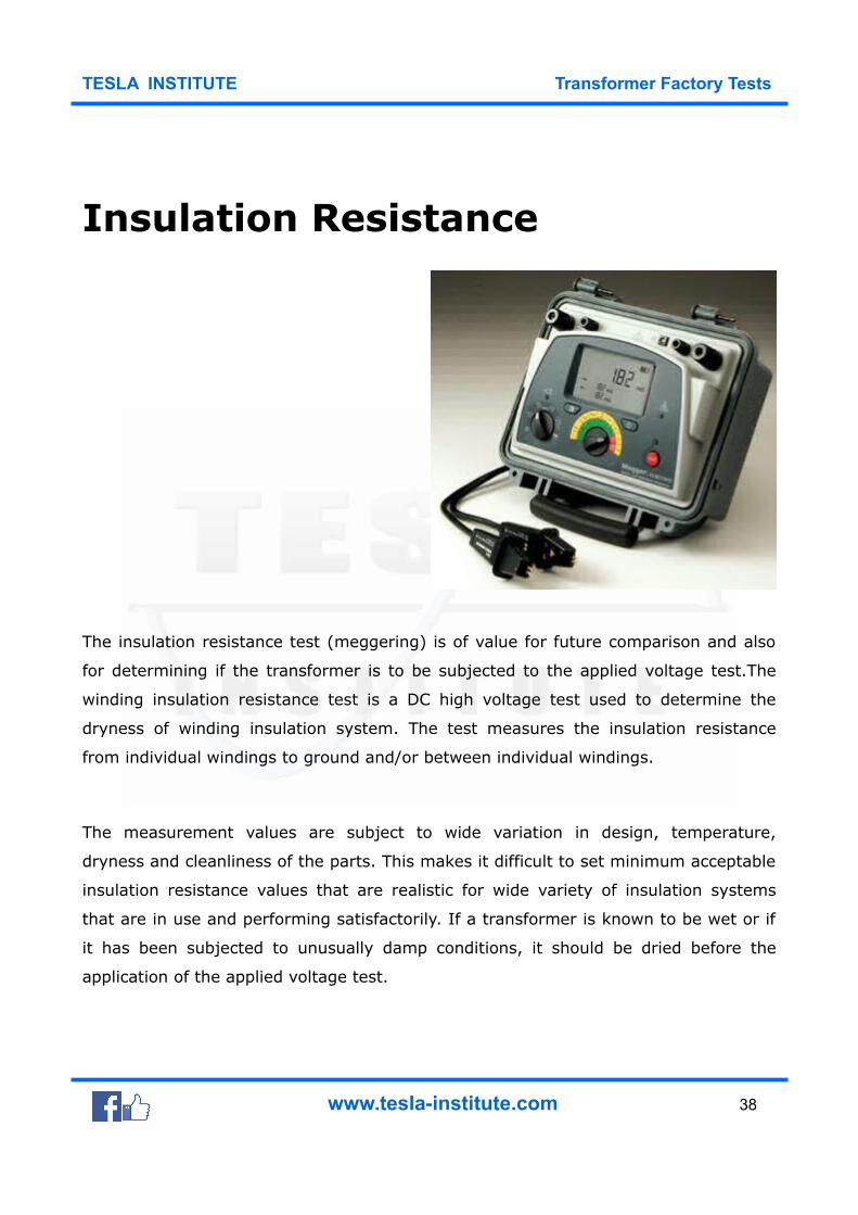
Insulation Resistance
The insulation resistance test (meggering) is of value for future comparison and also
for determining if the transformer is to be subjected to the applied voltage test.The
winding insulation resistance test is a DC high voltage test used to determine the
dryness of winding insulation system. The test measures the insulation resistance
from individual windings to ground and/or between individual windings.
The measurement values are subject to wide variation in design, temperature,
dryness and cleanliness of the parts. This makes it difficult to set minimum acceptable
insulation resistance values that are realistic for wide variety of insulation systems
that are in use and performing satisfactorily. If a transformer is known to be wet or if
it has been subjected to unusually damp conditions, it should be dried before the
application of the applied voltage test.
www.tesla-institute.com 38
TESLA INSTITUTE Transformer Factory Tests
Low readings can sometimes be brought up by cleaning or drying the apparatus. The
insulation resistance test should be performed at a transformer temperature as close
as possible or at 20 °C. Test conducted at other temperature should be corrected 20°C
with the use of temperature correcting factor.
The test equipment is calibrated to read in Megohm and commonly know as a HV
Megger. Typical maximum test set voltage values may be 1kV, 5kV or 15kV. The 30kV
Megger is also available.
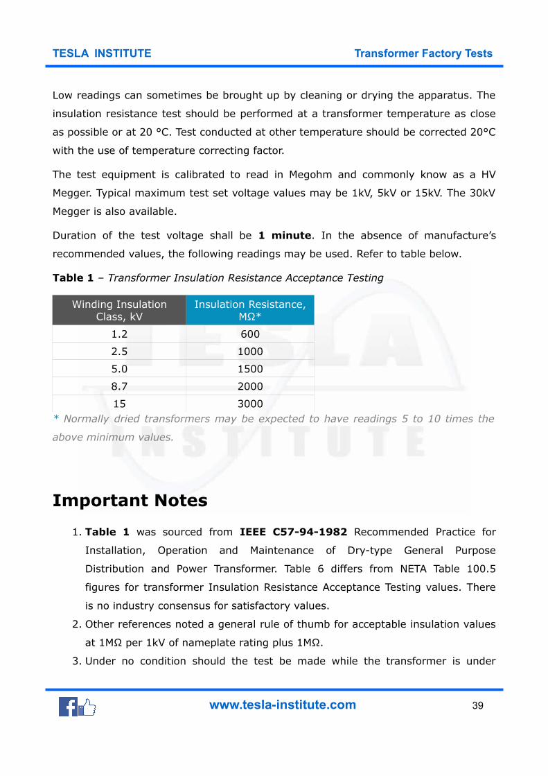
Duration of the test voltage shall be 1 minute. In the absence of manufacture’s
recommended values, the following readings may be used. Refer to table below.
Table 1 – Transformer Insulation Resistance Acceptance Testing
Winding InsulationClass, kV
Insulation Resistance,MΩ*
1.2 600
2.5 1000
5.0 1500
8.7 2000
15 3000* Normally dried transformers may be expected to have readings 5 to 10 times the
above minimum values.
Important Notes
1. Table 1 was sourced from IEEE C57-94-1982 Recommended Practice for
Installation, Operation and Maintenance of Dry-type General Purpose
Distribution and Power Transformer. Table 6 differs from NETA Table 100.5
figures for transformer Insulation Resistance Acceptance Testing values. There
is no industry consensus for satisfactory values.
2. Other references noted a general rule of thumb for acceptable insulation values
at 1MΩ per 1kV of nameplate rating plus 1MΩ.
3. Under no condition should the test be made while the transformer is under
www.tesla-institute.com 39
TESLA INSTITUTE Transformer Factory Tests
vacuum.
4. The significance of values of insulation resistance test requires some
interpretation depending on design, dryness and cleanliness of the insulation
involved. It is recommended that the insulation resistance values be measured
during periodic maintenance shutdown and trended. Large variation in the
trended values should be investigated for cause.
5. Insulation resistance may vary with applied voltage and any comparison should
be made with the same measurements at the same voltage and as close as
possible to the same equipment temperature and humidity as practically
possible.
Insulation Resistance Test Procedure
1. Isolate the equipment, apply working grounds to all incoming and outgoing
cables and disconnect all incoming and outgoing cables from the transformer
bushing terminals connections. Disconnected cables should have sufficient
clearance from the switchgear terminals greater that the phase spacing
distance. Use nylon rope to hold cable away from incoming and outgoing
terminals as required.
2. Ensure the transformer tank and core is grounded.
3. Disconnect all lightning arresters, fan system, meter or low voltage control
systems that are connected to the transformer winding.
4. Short circuit all winding terminals of the same voltage level together.
5. Perform a 1 minute resistance measurements between each winding group to
the other windings and ground.
6. Remove all shorting leads after completion of all test.
www.tesla-institute.com 40
TESLA INSTITUTE Transformer Factory Tests
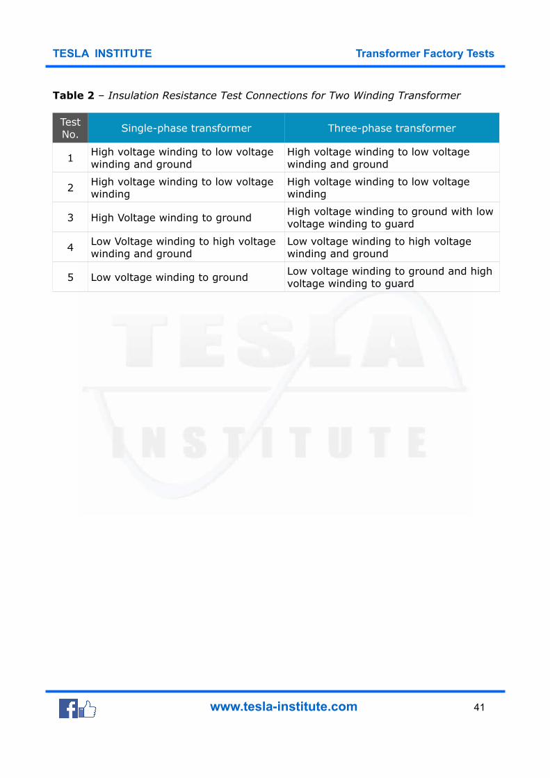
Table 2 – Insulation Resistance Test Connections for Two Winding Transformer
TestNo.
Single-phase transformer Three-phase transformer
1High voltage winding to low voltage winding and ground
High voltage winding to low voltage winding and ground
2 High voltage winding to low voltage winding
High voltage winding to low voltage winding
3 High Voltage winding to groundHigh voltage winding to ground with lowvoltage winding to guard
4 Low Voltage winding to high voltage winding and ground
Low voltage winding to high voltage winding and ground
5 Low voltage winding to groundLow voltage winding to ground and high voltage winding to guard
www.tesla-institute.com 41
TESLA INSTITUTE Transformer Factory Tests
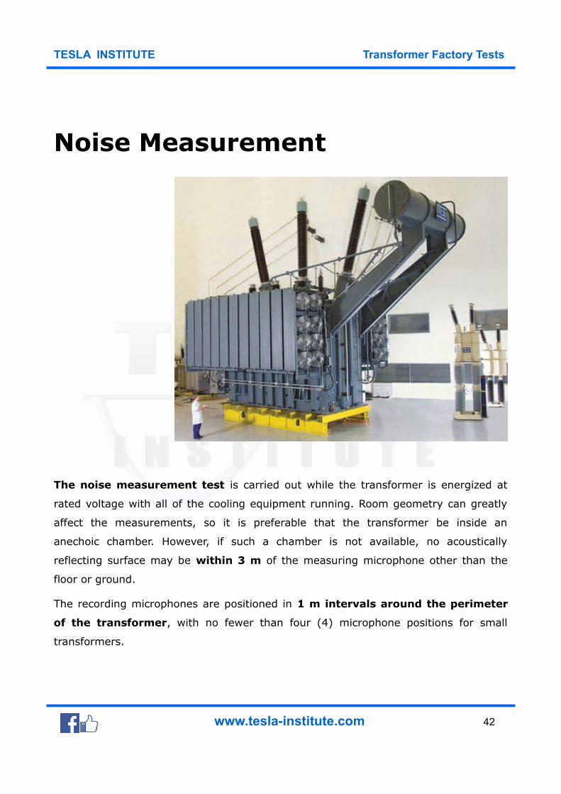
Noise Measurement
The noise measurement test is carried out while the transformer is energized at
rated voltage with all of the cooling equipment running. Room geometry can greatly
affect the measurements, so it is preferable that the transformer be inside an
anechoic chamber. However, if such a chamber is not available, no acoustically
reflecting surface may be within 3 m of the measuring microphone other than the
floor or ground.
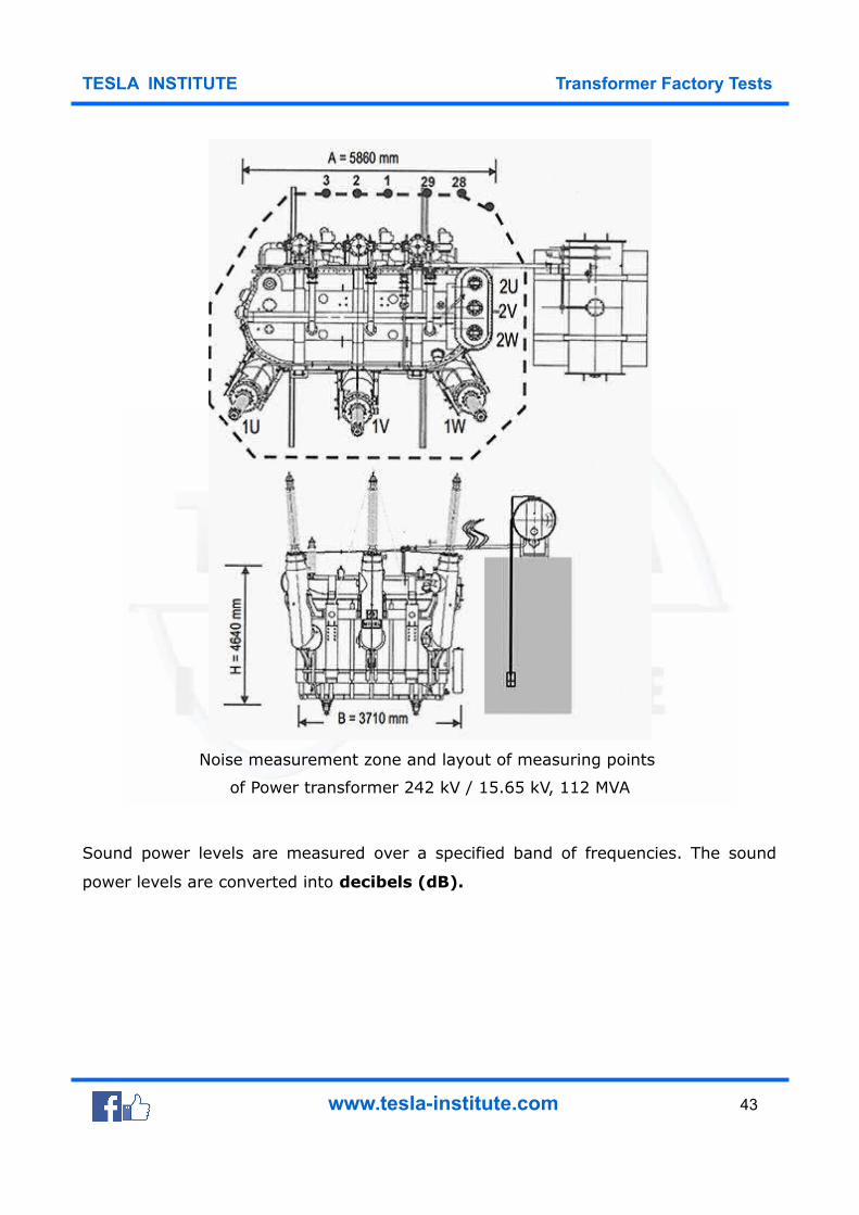
The recording microphones are positioned in 1 m intervals around the perimeter
of the transformer, with no fewer than four (4) microphone positions for small
transformers.
www.tesla-institute.com 42
TESLA INSTITUTE Transformer Factory Tests
Noise measurement zone and layout of measuring points
of Power transformer 242 kV / 15.65 kV, 112 MVA
Sound power levels are measured over a specified band of frequencies. The sound
power levels are converted into decibels (dB).
www.tesla-institute.com 43
TESLA INSTITUTE Transformer Factory Tests
Where all this noise is coming from?
Yes, we all know that transformers are never silent. This is actually quite impossible,
but in an environmentally aware, highly regulated world, the issue is not the level of
noise, but its nature – and it’s very important.
Transformers emit a low-frequency, tonal noise that people living in their vicinity
experience as an irritating “hum” and can hear even against a noisy background.
The power industry have a range of solutions to abate humming, which originates in
the transformer’s core and, when it is loaded, in the coil windings. Core noise is
generated by the magnetostriction (changes in shape) of the core’s laminations,
when a magnetic field passes through them. It is also known as no-load noise, as it
is dependent of the load passing through the transformer.
An effective and important noise source is the core of the transformer.
The noise of the core depends on the magnetic property of the core material (sheet
steel) and flux density. The sound frequency is low (twice the rated frequency). The
magnetic forces formed in the core cause vibration and noise. The load noise occurs
only on the loaded transforrmers and is added to the no-load (core noise). This noise
is caused by the electromagnetic forces due to leakage fields.
The source of the noise are tank walls, magnetic screenings and vibrations of
the windings.
The noises caused by the core and windings are mainly in the 100-600 Hz
frequency band. The frequency range of the noise (aerodynamic/air and
motor/bearing noise) caused by cooling fans is generally wide. The factors effecting
the total fan noise are; speed, blade structure, number of fans and arrangements
of the radiators.
The pump noise is not effective when the fans are working and it’s frequency is low.
www.tesla-institute.com 44
TESLA INSTITUTE Transformer Factory Tests
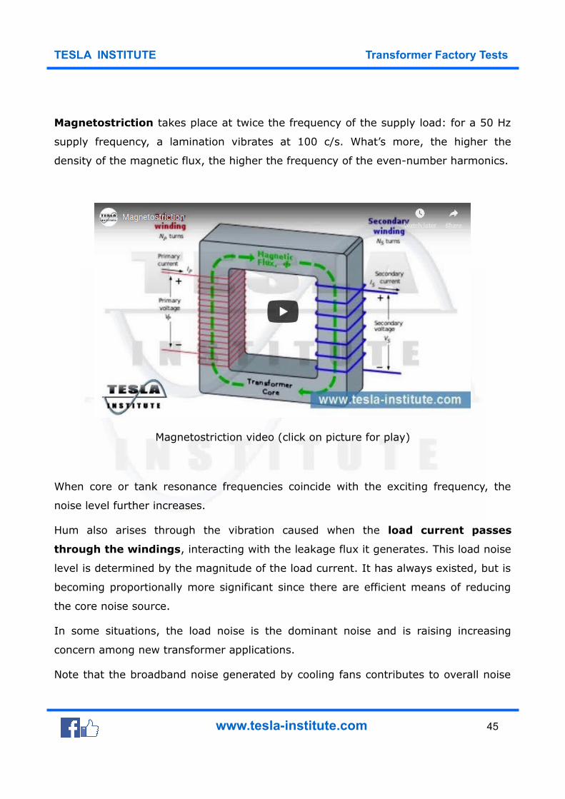
Magnetostriction takes place at twice the frequency of the supply load: for a 50 Hz
supply frequency, a lamination vibrates at 100 c/s. What’s more, the higher the
density of the magnetic flux, the higher the frequency of the even-number harmonics.
Magnetostriction video (click on picture for play)
When core or tank resonance frequencies coincide with the exciting frequency, the
noise level further increases.
Hum also arises through the vibration caused when the load current passes
through the windings, interacting with the leakage flux it generates. This load noise
level is determined by the magnitude of the load current. It has always existed, but is
becoming proportionally more significant since there are efficient means of reducing
the core noise source.
In some situations, the load noise is the dominant noise and is raising increasing
concern among new transformer applications.
Note that the broadband noise generated by cooling fans contributes to overall noise
www.tesla-institute.com 45
TESLA INSTITUTE Transformer Factory Tests
levels. But as cooling fans are widely used in the industry, solutions are not specific to
transmission and distribution and so are not discussed here.
Vibroacoustic energy sources in the
power transformers
Power transformer noise is mainly a low frequency narrow band noise, and the
noise spectrum includes the tonal components of the frequency being the multiple of
the power line frequency. The power transformers have many sources of vibroacoustic
energy.
The most important sources include:
1. The transformer core vibration as an effect of the magnetostriction
phenomena
2. The transformer winding vibration as an effect of the electrodynamic forces
3. The devices of the transformer cooling system, as fans, oil pumps.
Matters of design
Improvements in standard transformer design and materials are cutting the decibel
count.
High-permeability (Hi-B) steel, for example, restricts magnetostriction through a
surface coating with higher degrees of grain orientation.
Another increasingly popular method is high-precision stacking of the core’s
laminations in step-lap patterns, reducing the formation of air gaps in the core joints.
Focus on the linkages between the laminations to stop them striking each other
includes gluing their edges together, standardizing clamp pressure and removing
through-bolts.
www.tesla-institute.com 46
TESLA INSTITUTE Transformer Factory Tests
In addition, robust, flexible mounts at all points of contact between core and tank
inhibit the structure- or oil-borne transmission of resonance from one to the other.
Sound ways of seeing
Areva T&D’s R&D department employs acoustic imaging, acoustic holography and
laser vibrometry to locate noise and vibrations. Acoustic maps noise rapidly and
comprehensively by differentiating sound levels to determine where it radiates from.
Areva T&D and AB Engineering used 110-microphone arrays 2 m from the
tank to measure noise in the 100 Hz to 500 Hz frequency bands.
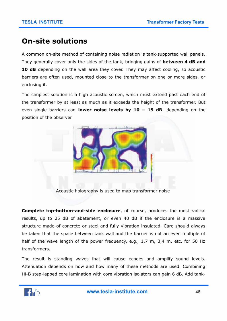
For each band, an identically scaled map showed red hot spots on noise-free blue
backgrounds, making it easy to pinpoint noise sources. Acoustic holography which
analyzes near-field noise, was recently used to map transformer noise, arranging a
23-microphone antenna to scan a grid of 20 x 20 cm squares. Algorithm-based
software computed the pressure field and sourced the acoustic radiation, displayed as
spatially distributed 2-D maps for different frequencies up to 850 Hz.
Laser vibrometry is a no-contact technique for inaccessible or dangerous targets. It
uses the Doppler effect, measuring the frequency modulation in the laser beam that
rebounds from the vibrating target. Laser vibrometers can automatically scan large
numbers of consecutive points, delivering vibration measurements with high spatial
resolution.
When a transformer is loaded, vibration energy from the coil and any flux control
devices is transmitted to the tank and then to the air and local environment. It is
therefore important to design the tank so that it does not resonate at frequencies
close to the exciting frequency. Measures like resonance absorbers can gain 3 dB.
www.tesla-institute.com 47
TESLA INSTITUTE Transformer Factory Tests
On-site solutions
A common on-site method of containing noise radiation is tank-supported wall panels.
They generally cover only the sides of the tank, bringing gains of between 4 dB and
10 dB depending on the wall area they cover. They may affect cooling, so acoustic
barriers are often used, mounted close to the transformer on one or more sides, or
enclosing it.
The simplest solution is a high acoustic screen, which must extend past each end of
the transformer by at least as much as it exceeds the height of the transformer. But
even single barriers can lower noise levels by 10 – 15 dB, depending on the
position of the observer.
Acoustic holography is used to map transformer noise
Complete top-bottom-and-side enclosure, of course, produces the most radical
results, up to 25 dB of abatement, or even 40 dB if the enclosure is a massive
structure made of concrete or steel and fully vibration-insulated. Care should always
be taken that the space between tank wall and the barrier is not an even multiple of
half of the wave length of the power frequency, e.g., 1,7 m, 3,4 m, etc. for 50 Hz
transformers.
The result is standing waves that will cause echoes and amplify sound levels.
Attenuation depends on how and how many of these methods are used. Combining
Hi-B step-lapped core lamination with core vibration isolators can gain 6 dB. Add tank-
www.tesla-institute.com 48
TESLA INSTITUTE Transformer Factory Tests
mounted wall panels and that is 10 dB.
For greater improvement, a total contact-free enclosure is the answer.
Of course, designers can build low noise into transformers by lowering the core’s
induction level, or flux density. But the trade-off is a larger core, larger windings and
higher costs.
Need for Research and Development
Reasearch and development is addressing the need for reduced sound levels.
Some abatement techniques are well known, but others can be very innovative, such
as resonance absorbers or resilient internal lining absorbers. Most of the selected
solutions require a good knowledge of noise field and vibration mapping. New
techniques are available to identify this information and to better characterize noise
sources.
Benefits can be a reduction of measurement time, facilitated interpretation of
measurements, access to other information (as in source localization), and more.
www.tesla-institute.com 49
TESLA INSTITUTE Transformer Factory Tests
Temperature Rise (Heat Run)
The transformer is energized at rated voltage in order to generate core losses. The
windings are connected to a loading transformer that simultaneously circulates rated
currents through all of the windings in order to develop load losses.
Naturally, the excitation voltage and the applied circulating currents are electrically
90° apart to minimize the KW requirements for this test. Nonetheless, a large power
transformer can consume up to 1 MW of total losses and the heat run test is an
expensive test to perform.
Therefore, in order to reduce the total expense, heat run tests are normally
performed on only one transformer on a purchase order for multiple transformers,
unless the customer chooses to pay for testing additional units.
www.tesla-institute.com 50
TESLA INSTITUTE Transformer Factory Tests
Short-Circuit Test
The short-circuit test is generally reserved for a sample transformer to verify the
design of a core and coil assembly unless the customer specifies that a short-
circuit test be performed on transformers that are purchased.
The customer should be cognizant of the ever-present risk of damaging the
transformer during short-circuit tests.
A low-voltage impulse (LVI) current waveform is applied to the transformer before and
after the applications of short-circuit test. The ‘‘before’’ and ‘‘after’’ oscillograms of
the LVI currents are compared for significant changes in waveshape that could
indicate mechanical damage to the windings.
www.tesla-institute.com 51
TESLA INSTITUTE Transformer Factory Tests
www.tesla-institute.com 52
TESLA INSTITUTE Transformer Factory Tests
www.tesla-institute.com 53

TESLA INSTITUTE Transformer Factory Tests
Like TESLA INSTITUTE Page !
Subscribe our Youtube channel !
Learn more withYoung English Engineer
www.tesla-institute.com 54