Embed Size (px)
Citation preview
Network+ Guide to Networks5th Edition
Chapter 7 WANs and Remote Connectivity
Objectives
• Identify a variety of uses for WANs• Explain different WAN topologies, including their
advantages and disadvantages• Compare the characteristics of WAN technologies,
including their switching type, throughput, media, security, and reliability
• Describe several WAN transmission and connection methods, including PSTN, ISDN, T-carriers, DSL, broadband cable, TM, and SONET
• Describe multiple methods for remotely connecting to a network
Network+ Guide to Networks, 5th Edition 2
WAN Essentials
• WAN– Network traversing some distance, connecting LANs– Transmission methods dependent on business needs
• WAN and LAN common properties– Client-host resource sharing, Layer 3 protocols, packet-
switched digitized data
• WAN and LAN differences– Layers 1 and 2 access methods, topologies, media– LAN wiring: private– WAN wiring: public through NSPs (network service
providers)
Network+ Guide to Networks, 5th Edition 3
Network+ Guide to Networks, 5th Edition 4
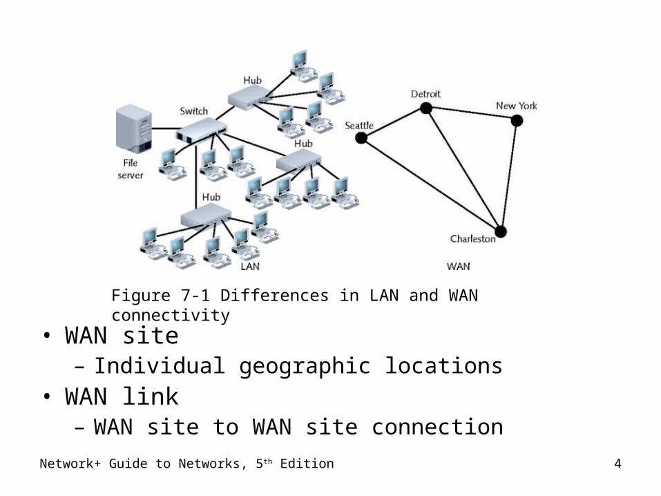
• WAN site– Individual geographic locations
• WAN link– WAN site to WAN site connection
Figure 7-1 Differences in LAN and WAN connectivity
Network+ Guide to Networks, 5th Edition 5
WAN Topologies
• Differences from LAN topologies– Distance covered, number of users, distance traveled– Connect sites via dedicated, high-speed links
• Use different connectivity devices
• WAN connections– Require Layer 3 devices
• Routers
– Not capable of nonroutable protocols
Network+ Guide to Networks, 5th Edition 6
Bus
• Each site connects to two sites maximum serially– Similar LAN topology site dependency
• Network site dependent on every other site to transmit and receive traffic
– Difference from LAN topology• Different locations connected to another through point-
to-point links
• Best use– Organizations requiring small WAN, dedicated circuits
• Drawback– Not scalable
Network+ Guide to Networks, 5th Edition 7
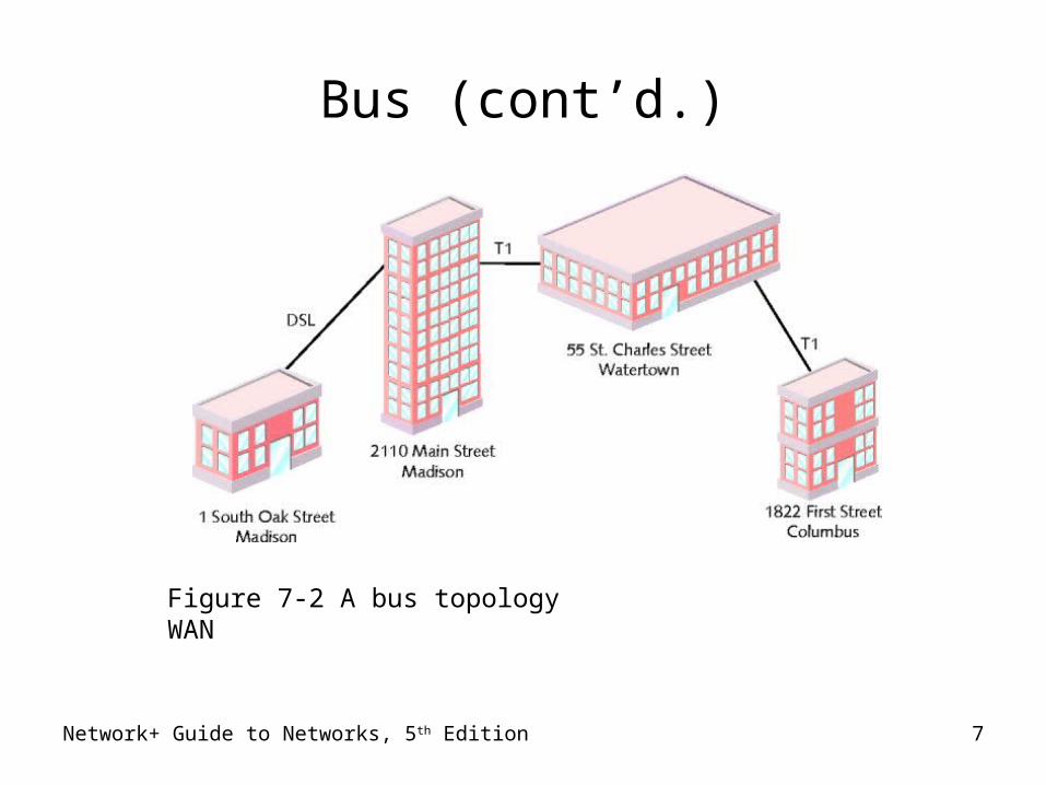
Bus (cont’d.)
Figure 7-2 A bus topology WAN
Ring
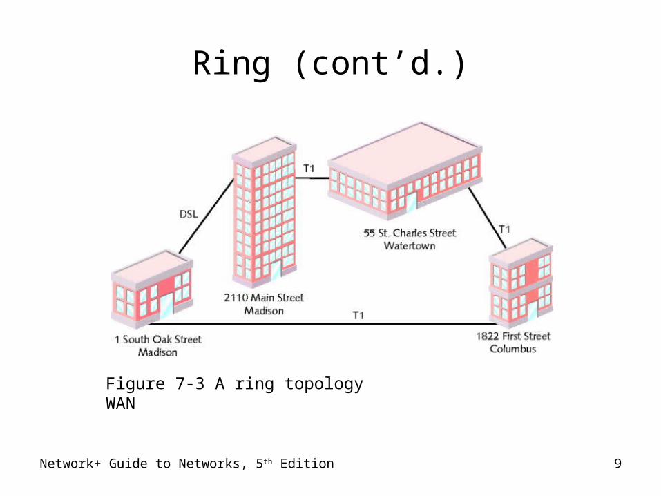
• Each site connected to two other sites– Forms ring pattern
• Similar to LAN ring topology
• Differences from LAN ring topology– Connects locations
– Relies on redundant rings• Data rerouted upon site failure
– Expansion• Difficult, expensive
• Best use– Connecting four, five locations maximum
Network+ Guide to Networks, 5th Edition 8
Network+ Guide to Networks, 5th Edition 9
Ring (cont’d.)
Figure 7-3 A ring topology WAN
Star
• Mimics star topology LAN– Single site central connection point– Separate data routes between any two sites
• Advantages– Single connection failure affects one location
• Different from bus, star topology
– Shorter data paths between any two sites• When all dedicated circuits functioning
– Expansion: simple, less costly
• Drawback– Central site failure
Network+ Guide to Networks, 5th Edition 10
Network+ Guide to Networks, 5th Edition 11
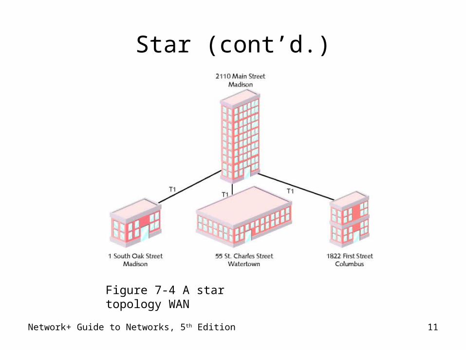
Star (cont’d.)
Figure 7-4 A star topology WAN
Network+ Guide to Networks, 5th Edition 12
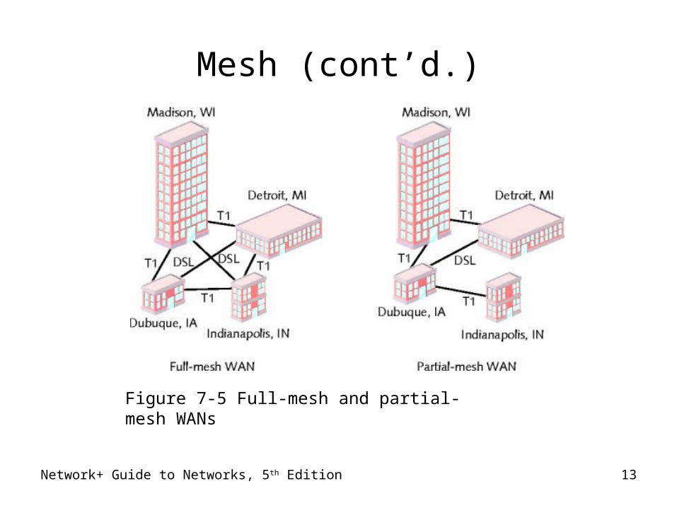
Mesh
• Incorporates many directly interconnected sites– Data travels directly from origin to destination– Routers can redirect data easily, quickly
• Most fault-tolerant WAN type
• Full-mesh WAN– Every WAN site directly connected to every other site– Drawback: cost
• Partial-mesh WAN– Reduce costs
Network+ Guide to Networks, 5th Edition 13
Mesh (cont’d.)
Figure 7-5 Full-mesh and partial-mesh WANs
Network+ Guide to Networks, 5th Edition 14
Tiered
• Sites connected in star or ring formations– Interconnected at different levels– Interconnection points organized into layers
• Form hierarchical groupings
• Flexibility– Allows many variations, practicality– Requires careful considerations:
• Geography, usage patterns, growth potential
Network+ Guide to Networks, 5th Edition 15
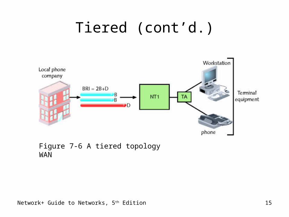
Tiered (cont’d.)
Figure 7-6 A tiered topology WAN
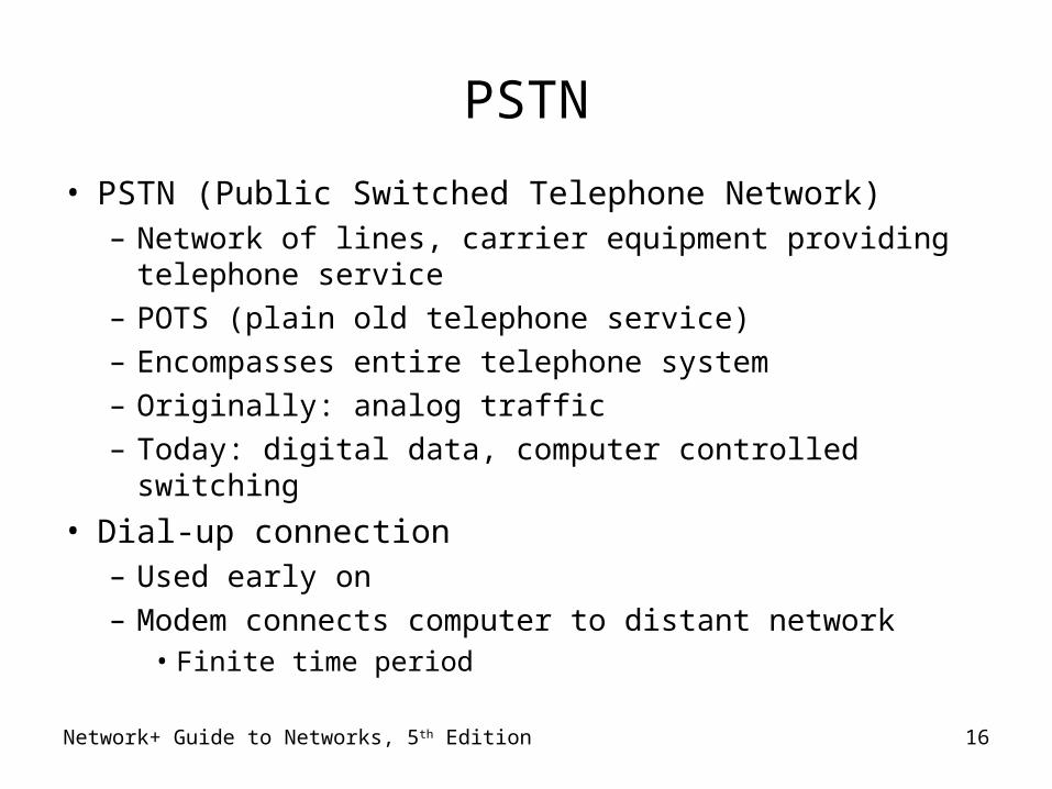
PSTN
• PSTN (Public Switched Telephone Network)– Network of lines, carrier equipment providing telephone
service– POTS (plain old telephone service)– Encompasses entire telephone system– Originally: analog traffic– Today: digital data, computer controlled switching
• Dial-up connection– Used early on– Modem connects computer to distant network
• Finite time period
Network+ Guide to Networks, 5th Edition 16

Network+ Guide to Networks, 5th Edition 17
PSTN (cont’d.)
• PSTN elements– Cannot handle digital transmission
• Requires modem
• Signal travels path between modems– Over carrier’s network
• Includes CO (central office), remote switching facility
• Signal converts back to digital pulses
• CO (central office)– Where telephone company terminates lines– Switches calls between different locations
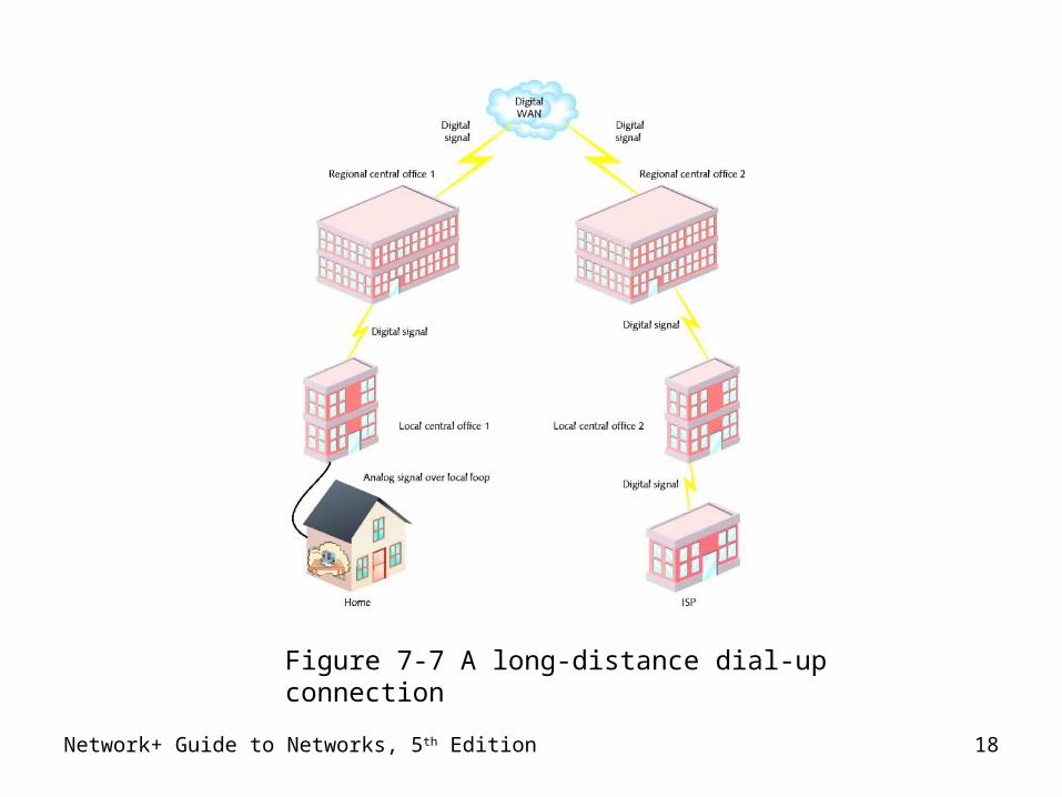
Network+ Guide to Networks, 5th Edition 18
Figure 7-7 A long-distance dial-up connection
Network+ Guide to Networks, 5th Edition 19
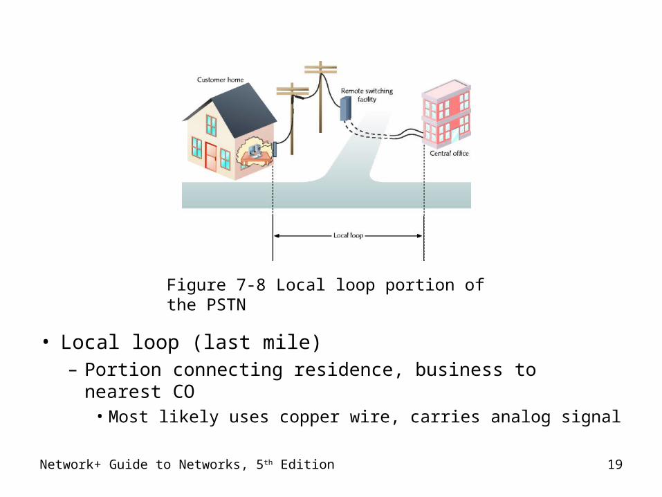
• Local loop (last mile)– Portion connecting residence, business to nearest CO
• Most likely uses copper wire, carries analog signal
Figure 7-8 Local loop portion of the PSTN

PSTN (cont’d.)
• Demarcation point– Local loop endpoint– Carriers responsibility ends– Wires terminate at NIU (network interface unit)
• PSTN Internet connection advantage– Ubiquity, ease of use, low cost
• PSTN disadvantage– Some circuit switching used– Marginal security
Network+ Guide to Networks, 5th Edition 20
X.25 and Frame Relay
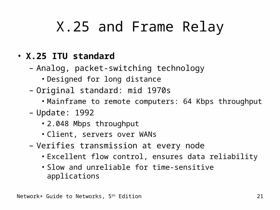
• X.25 ITU standard– Analog, packet-switching technology
• Designed for long distance
– Original standard: mid 1970s• Mainframe to remote computers: 64 Kbps throughput
– Update: 1992• 2.048 Mbps throughput
• Client, servers over WANs
– Verifies transmission at every node• Excellent flow control, ensures data reliability
• Slow and unreliable for time-sensitive applicationsNetwork+ Guide to Networks, 5th Edition 21
Network+ Guide to Networks, 5th Edition 22
X.25 and Frame Relay (cont’d.)
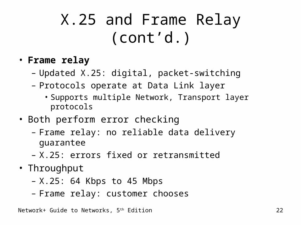
• Frame relay– Updated X.25: digital, packet-switching– Protocols operate at Data Link layer
• Supports multiple Network, Transport layer protocols
• Both perform error checking– Frame relay: no reliable data delivery guarantee– X.25: errors fixed or retransmitted
• Throughput– X.25: 64 Kbps to 45 Mbps– Frame relay: customer chooses
X.25 and Frame Relay (cont’d.)
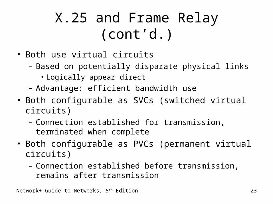
• Both use virtual circuits– Based on potentially disparate physical links
• Logically appear direct
– Advantage: efficient bandwidth use
• Both configurable as SVCs (switched virtual circuits)– Connection established for transmission, terminated
when complete
• Both configurable as PVCs (permanent virtual circuits)– Connection established before transmission, remains
after transmissionNetwork+ Guide to Networks, 5th Edition 23
Network+ Guide to Networks, 5th Edition 24
X.25 and Frame Relay (cont’d.)
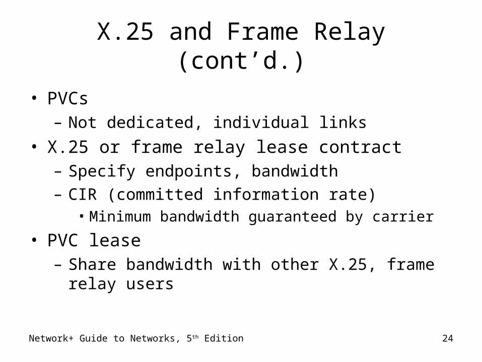
• PVCs– Not dedicated, individual links
• X.25 or frame relay lease contract– Specify endpoints, bandwidth– CIR (committed information rate)
• Minimum bandwidth guaranteed by carrier
• PVC lease– Share bandwidth with other X.25, frame relay users
Network+ Guide to Networks, 5th Edition 25
X.25 and Frame Relay (cont’d.)
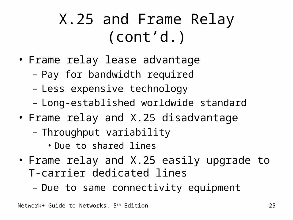
• Frame relay lease advantage– Pay for bandwidth required– Less expensive technology– Long-established worldwide standard
• Frame relay and X.25 disadvantage– Throughput variability
• Due to shared lines
• Frame relay and X.25 easily upgrade to T-carrier dedicated lines– Due to same connectivity equipment
Network+ Guide to Networks, 5th Edition 26
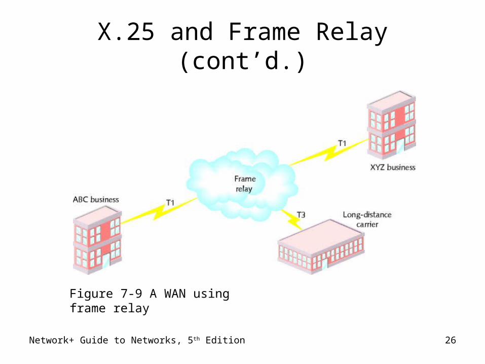
X.25 and Frame Relay (cont’d.)
Figure 7-9 A WAN using frame relay
Network+ Guide to Networks, 5th Edition 27
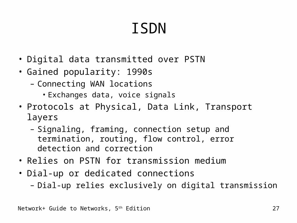
ISDN
• Digital data transmitted over PSTN
• Gained popularity: 1990s– Connecting WAN locations
• Exchanges data, voice signals
• Protocols at Physical, Data Link, Transport layers– Signaling, framing, connection setup and termination,
routing, flow control, error detection and correction
• Relies on PSTN for transmission medium
• Dial-up or dedicated connections– Dial-up relies exclusively on digital transmission
Network+ Guide to Networks, 5th Edition 28
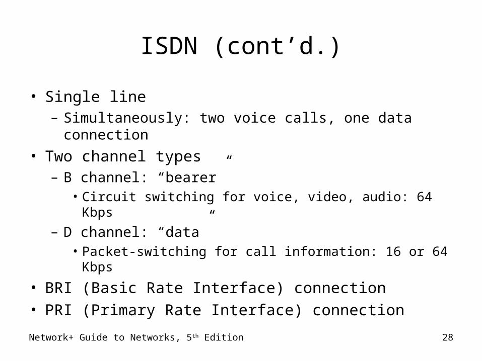
ISDN (cont’d.)
• Single line– Simultaneously: two voice calls, one data connection
• Two channel types– B channel: “bearer”
• Circuit switching for voice, video, audio: 64 Kbps
– D channel: “data” • Packet-switching for call information: 16 or 64 Kbps
• BRI (Basic Rate Interface) connection
• PRI (Primary Rate Interface) connection
Network+ Guide to Networks, 5th Edition 29
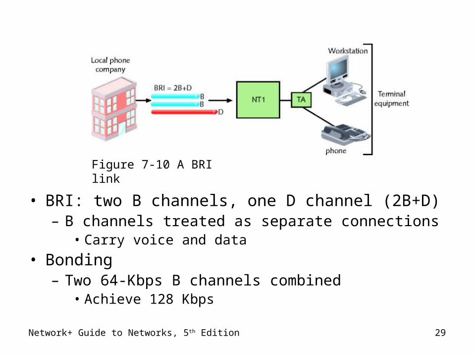
• BRI: two B channels, one D channel (2B+D)– B channels treated as separate connections
• Carry voice and data
• Bonding– Two 64-Kbps B channels combined
• Achieve 128 Kbps
Figure 7-10 A BRI link
Network+ Guide to Networks, 5th Edition 30
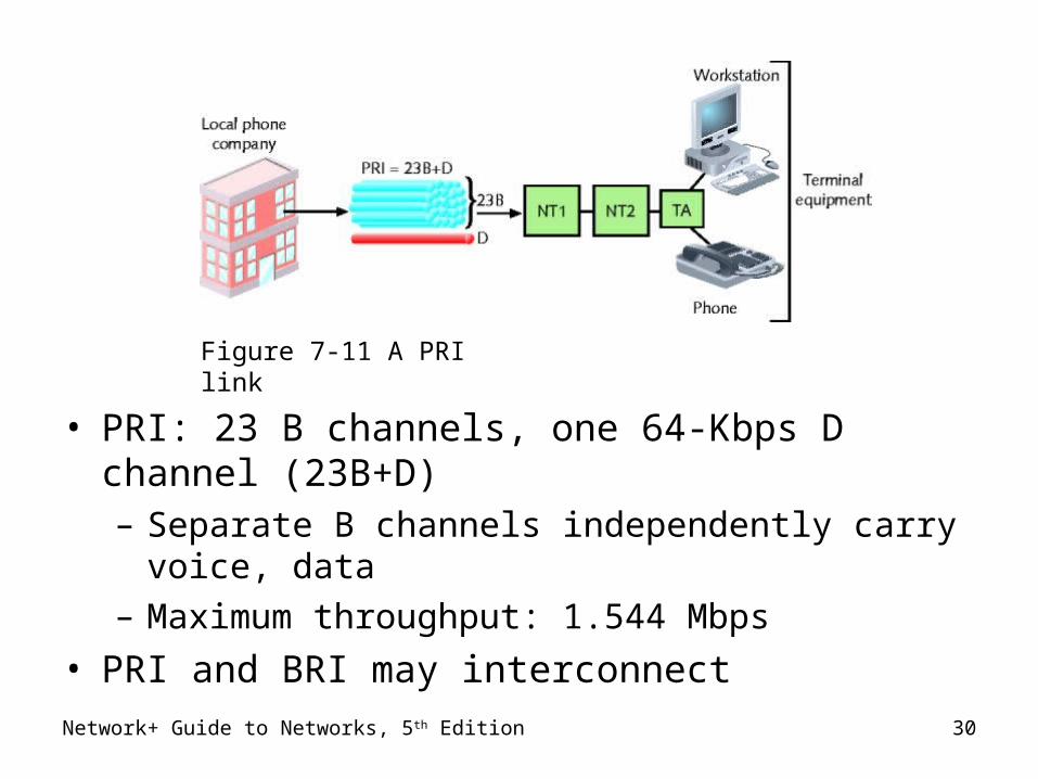
• PRI: 23 B channels, one 64-Kbps D channel (23B+D)– Separate B channels independently carry voice, data– Maximum throughput: 1.544 Mbps
• PRI and BRI may interconnect
Figure 7-11 A PRI link
Network+ Guide to Networks, 5th Edition 31
T-Carriers
• T1s, fractional T1s, T3s
• Physical layer operation
• Single channel divided into multiple channels– Using TDM (time division multiplexing) over two wire
pairs
• Medium– Telephone wire, fiber-optic cable, wireless links
Network+ Guide to Networks, 5th Edition 32
Types of T-Carriers
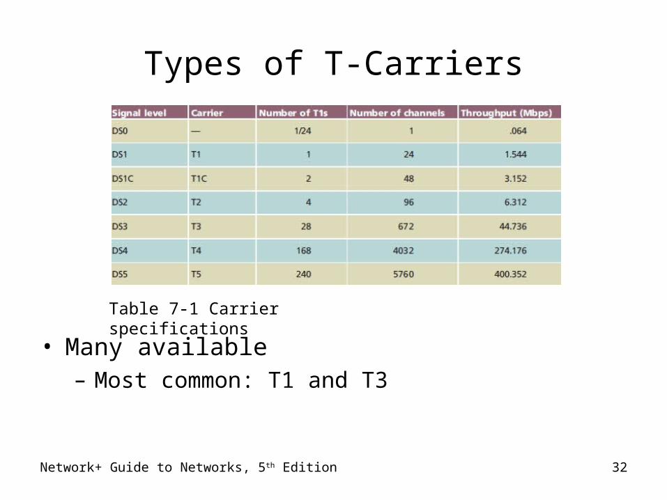
• Many available– Most common: T1 and T3
Table 7-1 Carrier specifications
Network+ Guide to Networks, 5th Edition 33
Types of T-Carriers (cont’d.)
• T1: 24 voice or data channels– Maximum data throughput: 1.544 Mbps
• T3: 672 voice or data channels– Maximum data throughput: 44.736 Mbps (45 Mbps)
• T-carrier speed dependent on signal level– Physical layer electrical signaling characteristics– DS0 (digital signal, level 0)
• One data, voice channel

Network+ Guide to Networks, 5th Edition 34
Types of T-Carriers (cont’d.)
• T1 use– Connects branch offices, connects to carrier– Connects telephone company COs, ISPs
• T3 use– Data-intensive businesses
• T3 provides 28 times more throughput (expensive)– Multiple T1’s may accommodate needs
• TI costs vary by region• Fractional T1 lease
– Use some T1 channels, charged accordingly
Network+ Guide to Networks, 5th Edition 35
T-Carrier Connectivity
• T-carrier line requires connectivity hardware– Customer site, switching facility– Purchased or leased– Cannot be used with other WAN transmission
methods
• T-carrier line requires different media– Throughput dependent
Network+ Guide to Networks, 5th Edition 36
T-Carrier Connectivity (cont’d.)
• Wiring– Plain telephone wire
• UTP or STP copper wiring
• STP preferred for clean connection
– Coaxial cable, microwave, fiber-optic cable– T1s using STP require repeater every 6000 feet– Multiple T1s
• Coaxial cable, microwave, fiber-optic cabling
– T3s require microwave, fiber-optic cabling
Network+ Guide to Networks, 5th Edition 37
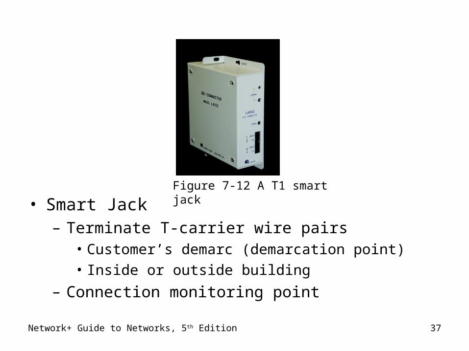
• Smart Jack– Terminate T-carrier wire pairs
• Customer’s demarc (demarcation point)
• Inside or outside building
– Connection monitoring point
Figure 7-12 A T1 smart jack
Network+ Guide to Networks, 5th Edition 38
T-Carrier Connectivity (cont’d.)
• CSU/DSU (Channel Service Unit/Data Service Unit)– Two separate devices– Combined into single stand-alone device
• Interface card
– T1 line connection point• At customer’s site
• CSU– Provides digital signal termination– Ensures connection integrity
Network+ Guide to Networks, 5th Edition 39
T-Carrier Connectivity (cont’d.)
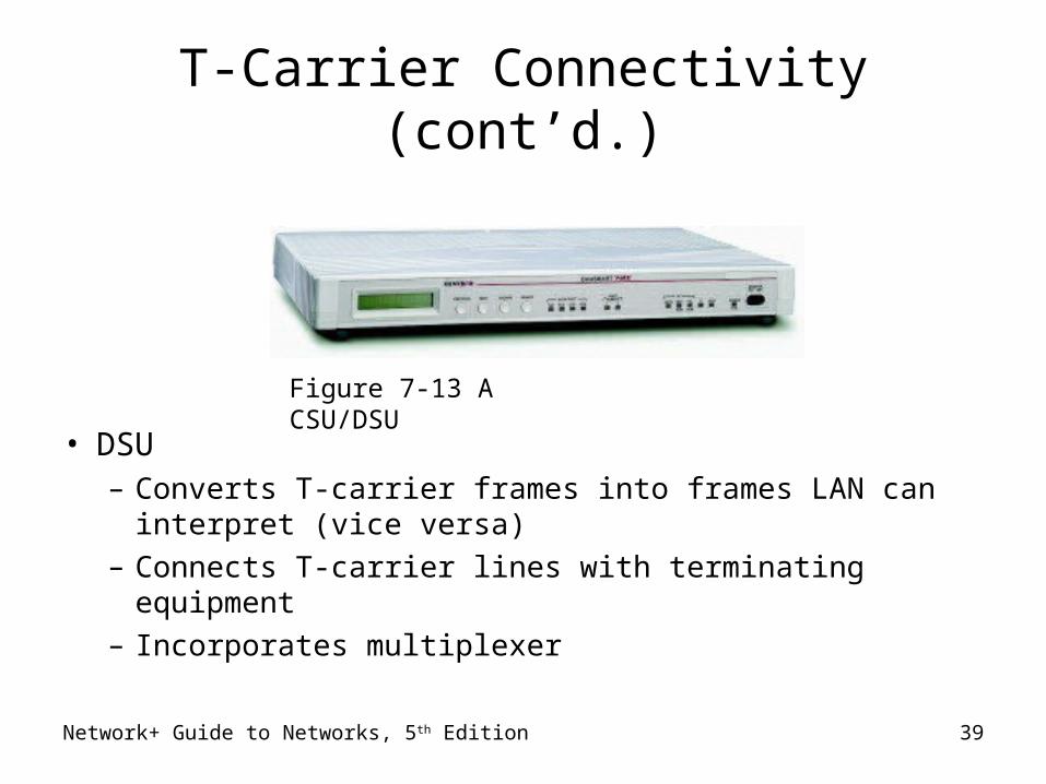
• DSU– Converts T-carrier frames into frames LAN can
interpret (vice versa)– Connects T-carrier lines with terminating equipment– Incorporates multiplexer
Figure 7-13 A CSU/DSU
Network+ Guide to Networks, 5th Edition 40
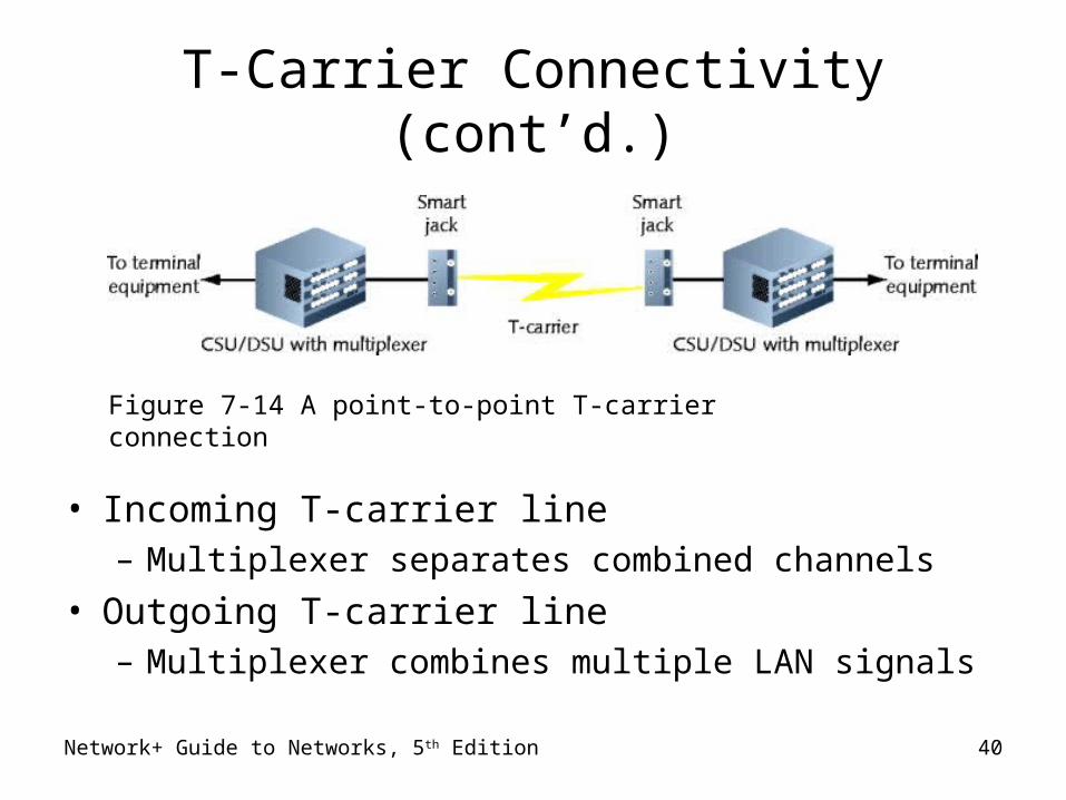
T-Carrier Connectivity (cont’d.)
• Incoming T-carrier line– Multiplexer separates combined channels
• Outgoing T-carrier line– Multiplexer combines multiple LAN signals
Figure 7-14 A point-to-point T-carrier connection
Network+ Guide to Networks, 5th Edition 41
T-Carrier Connectivity (cont’d.)
• Terminal Equipment– Switches, routers, bridges– Best option: router, Layer 3 or higher switch
• Accepts incoming CSU/DSU signals• Translates Network layer protocols• Directs data to destination
• CSU/DSU may be integrated with router, switch– Expansion card– Faster signal processing, better performance– Less expensive, lower maintenance solution
Network+ Guide to Networks, 5th Edition 42
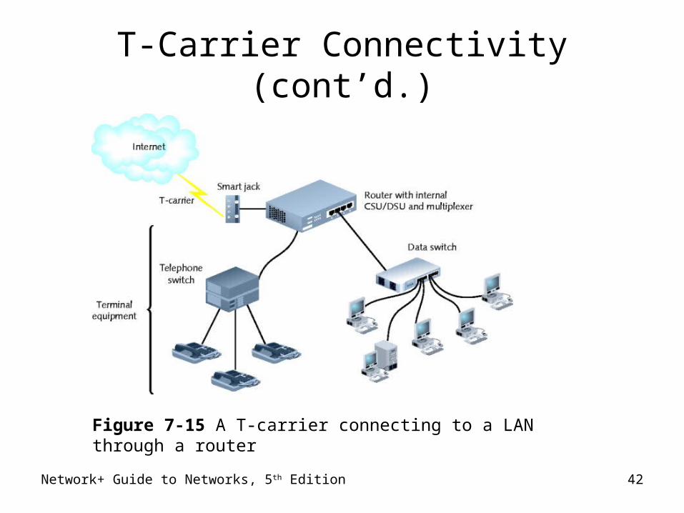
T-Carrier Connectivity (cont’d.)
Figure 7-15 A T-carrier connecting to a LAN through a router
DSL
• DSL (digital subscriber line)– Operates over PSTN– Directly competes with ISDN, T1 services– Requires repeaters for longer distances– Best suited for WAN local loop– Supports multiple data, voice channels
• Over single line
• Higher, inaudible telephone line frequencies
– Uses advanced data modulation techniques• Data signal alters carrier signal properties
• Amplitude or phase modulation
Network+ Guide to Networks, 5th Edition 43
Network+ Guide to Networks, 5th Edition 44
Types of DSL
• xDSL refers to all DSL varieties– ADSL, G.Lite, HDSL, SDSL, VDSL, SHDSL
• Two DSL categories– Asymmetrical and symmetrical
• Downstream– Data travels from carrier’s switching facility to
customer
• Upstream– Data travels from customer to carrier’s switching
facility
Network+ Guide to Networks, 5th Edition 45
Types of DSL (cont’d.)
• Downstream, upstream throughput rates may differ– Asymmetrical
• More throughput in one direction
• Downstream throughput higher than upstream throughput
• Best use: video conferencing, web surfing
– Symmetrical• Equal capacity for upstream, downstream data
• Examples : HDSL, SDSL, SHDSL
• Best use: uploading, downloading significant data amounts
Network+ Guide to Networks, 5th Edition 46
Types of DSL (cont’d.)
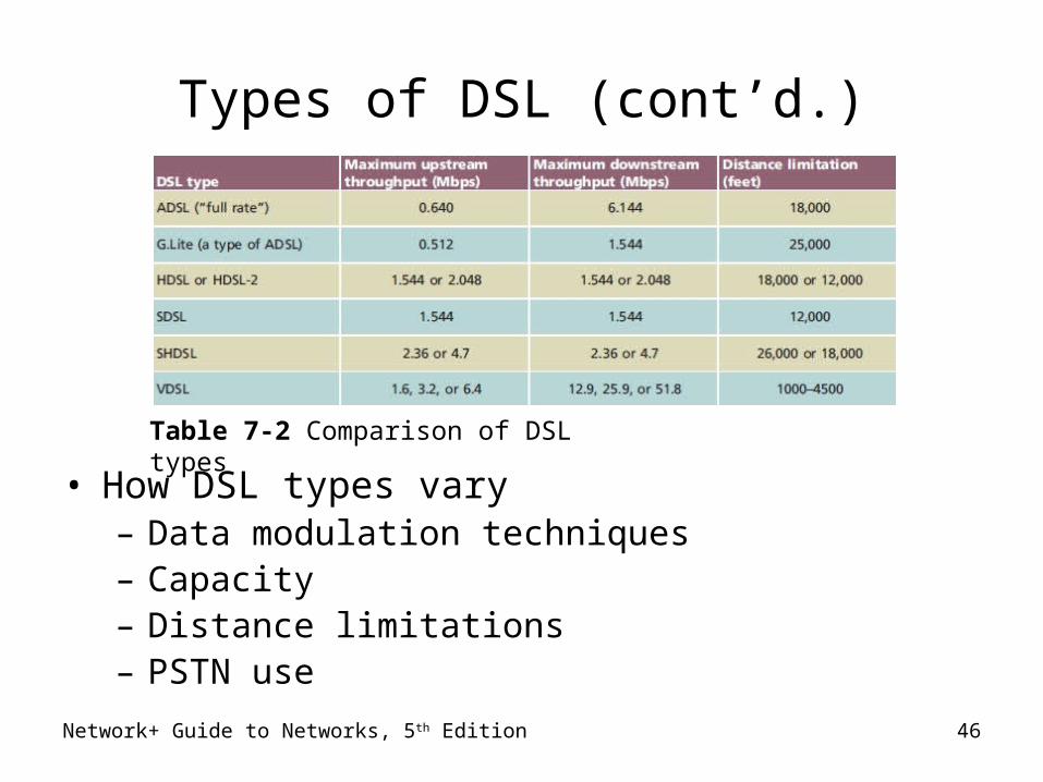
• How DSL types vary– Data modulation techniques– Capacity– Distance limitations– PSTN use
Table 7-2 Comparison of DSL types
Network+ Guide to Networks, 5th Edition 47
DSL Connectivity
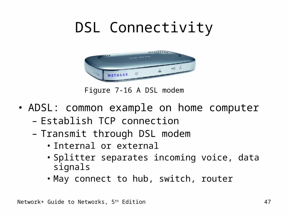
• ADSL: common example on home computer– Establish TCP connection– Transmit through DSL modem
• Internal or external• Splitter separates incoming voice, data signals• May connect to hub, switch, router
Figure 7-16 A DSL modem
DSL Connectivity (cont’d.)
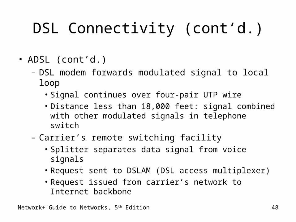
• ADSL (cont’d.)– DSL modem forwards modulated signal to local loop
• Signal continues over four-pair UTP wire
• Distance less than 18,000 feet: signal combined with other modulated signals in telephone switch
– Carrier’s remote switching facility• Splitter separates data signal from voice signals
• Request sent to DSLAM (DSL access multiplexer)
• Request issued from carrier’s network to Internet backbone
Network+ Guide to Networks, 5th Edition 48
Network+ Guide to Networks, 5th Edition 49
DSL Connectivity (cont’d.)
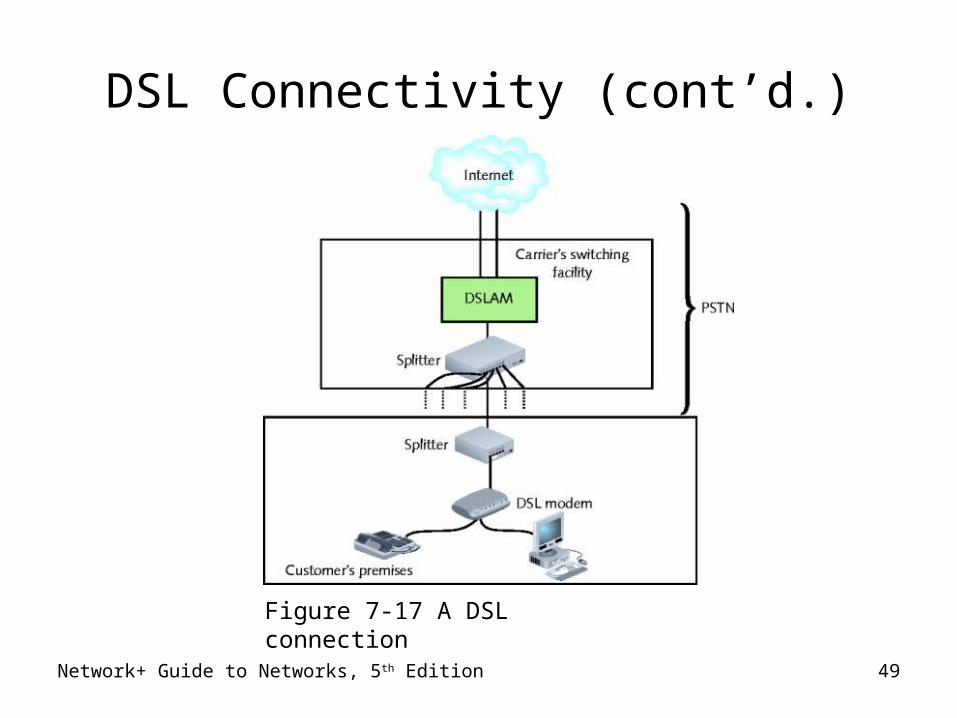
Figure 7-17 A DSL connection
Network+ Guide to Networks, 5th Edition 50
DSL Connectivity (cont’d.)
• DSL competition– T1, ISDN, broadband cable
• DSL installation– Hardware, monthly access costs
• Slightly less than ISDN, significantly less than T1s
• DSL drawbacks– Not available in all areas– Upstream throughput lower than broadband cable
• Consumers use broadband Internet access service
Broadband Cable
• Cable companies connectivity option
• Based on TV signals coaxial cable wiring– Theoretically transmission
• 150 Mbps downstream, 10 Mbps upstream
– Real transmission• 10 Mbps downstream, 2 Mbps upstream• Transmission limited ( throttled)• Shared physical connections
• Best use– Web surfing– Network data download
Network+ Guide to Networks, 5th Edition 51
Network+ Guide to Networks, 5th Edition 52
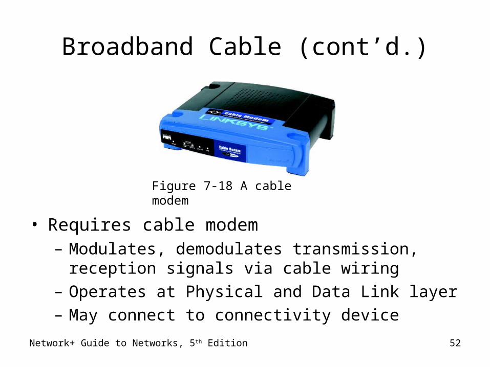
Broadband Cable (cont’d.)
• Requires cable modem– Modulates, demodulates transmission, reception
signals via cable wiring– Operates at Physical and Data Link layer– May connect to connectivity device
Figure 7-18 A cable modem
Broadband Cable (cont’d.)
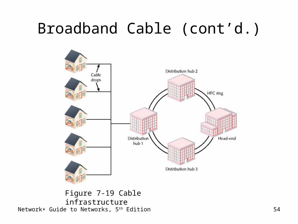
• Infrastructure required– HFC (hybrid fiber-coax)
• Expensive fiber-optic link supporting high frequencies
• connects cable company’s offices to node
• Location near customer
– Cable drop• Connects node to customer’s business or residence
• Fiber-optic or coaxial cable
• Connects to head end
• Provides dedicated connection
• Many subscribers share same local line, throughputNetwork+ Guide to Networks, 5th Edition 53
Network+ Guide to Networks, 5th Edition 54
Figure 7-19 Cable infrastructure
Broadband Cable (cont’d.)
ATM (Asynchronous Transfer Mode)
• Functions in Data Link layer
• Asynchronous communications method– Nodes do not conform to predetermined schemes
• Specifying data transmissions timing
– Each character transmitted• Start and stop bits
• Specifies Data Link layer framing techniques
• Fixed packet size– Sets ATM apart from Ethernet– Packet (cell)
• 48 data bytes plus 5-byte header
Network+ Guide to Networks, 5th Edition 55
Network+ Guide to Networks, 5th Edition 56
ATM (cont’d.)
• Smaller packet size requires more overhead– Decrease potential throughput– Cell efficiency compensates for loss
• ATM relies on virtual circuits– ATM considered packet-switching technology– Virtual circuits provide circuit switching advantage
• Reliably available point-to-point connection
– Reliable connection
• Allows specific QoS (quality of service) guarantee– Important for time-sensitive applications
ATM (cont’d.)
• Compatibility– Other leading network technologies
– Cells support multiple higher-layer protocol
– LANE (LAN Emulation)• Allows integration with Ethernet, token ring network• encapsulates incoming Ethernet or token ring frames• Converts to ATM cells for transmission
• Throughput – 25 Mbps to 622 Mbps
• Cost– Relatively expensive
Network+ Guide to Networks, 5th Edition 57
Network+ Guide to Networks, 5th Edition 58
SONET (Synchronous Optical Network)
• Four key strengths– WAN technology integration– Fast data transfer rates– Simple link additions, removals– High degree of fault tolerance
• Synchronous– Data transmitted, received by nodes conforms to
timing scheme
• Advantage– Interoperability
Network+ Guide to Networks, 5th Edition 59
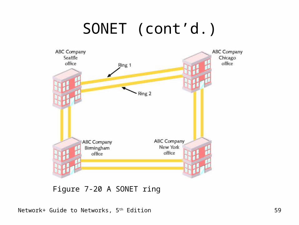
SONET (cont’d.)
Figure 7-20 A SONET ring
Network+ Guide to Networks, 5th Edition 60
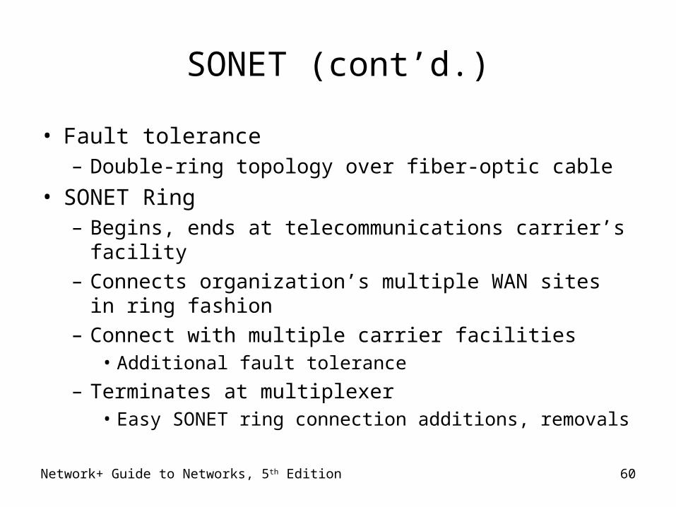
SONET (cont’d.)
• Fault tolerance– Double-ring topology over fiber-optic cable
• SONET Ring– Begins, ends at telecommunications carrier’s facility– Connects organization’s multiple WAN sites in ring
fashion– Connect with multiple carrier facilities
• Additional fault tolerance
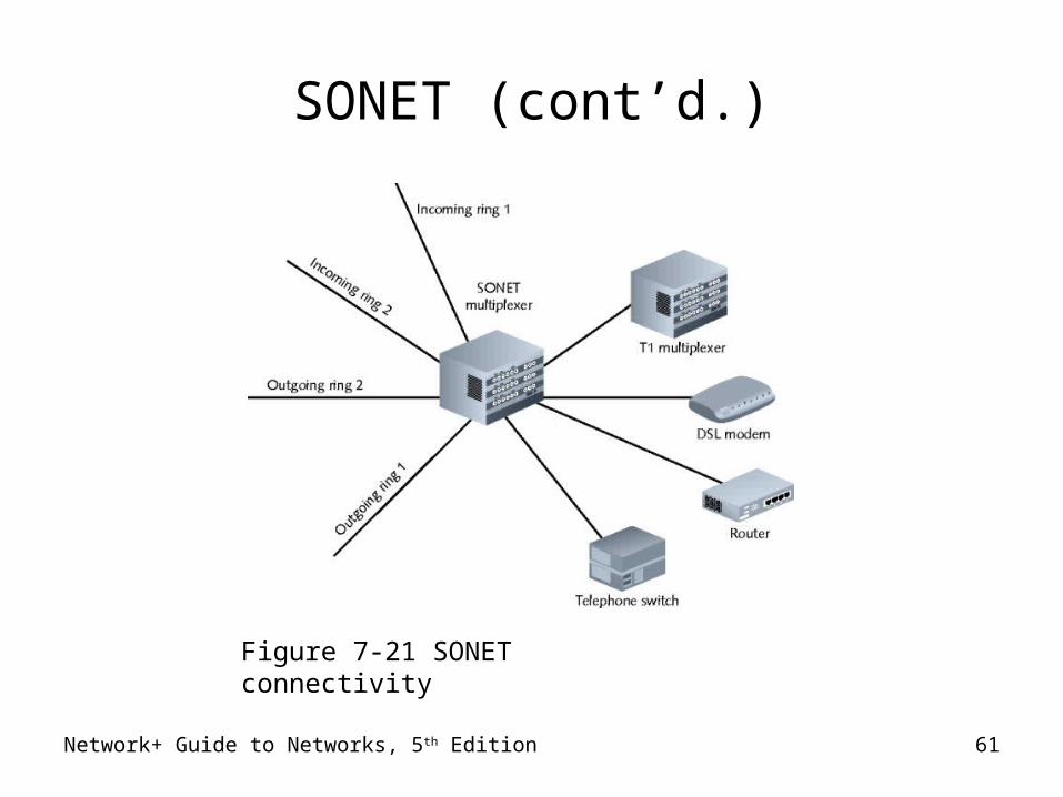
– Terminates at multiplexer• Easy SONET ring connection additions, removals
Network+ Guide to Networks, 5th Edition 61
SONET (cont’d.)
Figure 7-21 SONET connectivity
Network+ Guide to Networks, 5th Edition 62
SONET (cont’d.)
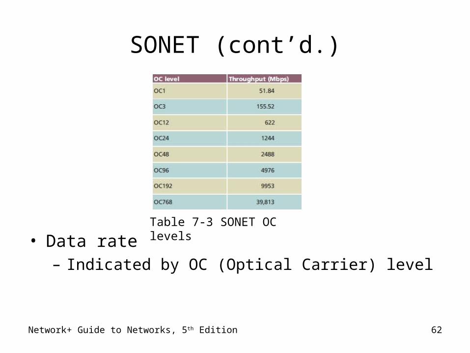
• Data rate– Indicated by OC (Optical Carrier) level
Table 7-3 SONET OC levels
Network+ Guide to Networks, 5th Edition 63
SONET (cont’d.)
• Implementation– Large companies– Long-distance companies
• Linking metropolitan areas and countries
– ISPs• Guarantying fast, reliable Internet access
– Telephone companies• Connecting Cos
• COST– Expensive
Network+ Guide to Networks, 5th Edition 64
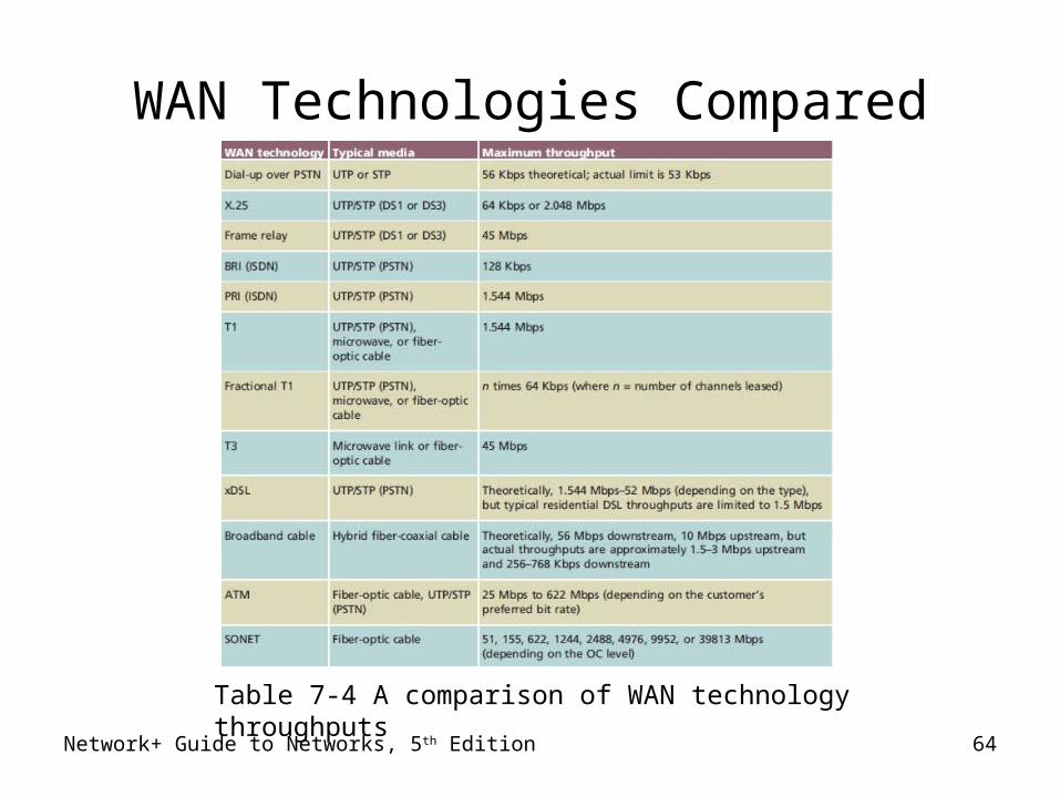
WAN Technologies Compared
Table 7-4 A comparison of WAN technology throughputs
Network+ Guide to Networks, 5th Edition 65
Remote Connectivity
• Remote access– Service allowing client connection, log on capability
• LAN or WAN in different geographical location
• Remote client– Access files, applications, shared resources
• Remote access communication requirement– Client, host transmission path– Appropriate software– Dial-up networking, Microsoft’s RAS or RRAS, VPNs
Network+ Guide to Networks, 5th Edition 66
Dial-Up Networking
• Dialing directly into private network’s or ISP’s remote access server– Log on to network
• Transmission methods– PSTN, X.25, ISDN
Network+ Guide to Networks, 5th Edition 67
Dial-Up Networking (cont’d.)
• Advantages– Technology well understood– Software availability
• Disadvantages– Throughput– Quality– Administrative maintenance
• Microsoft software– RAS (Remote Access Service)– RRAS (Routing and Remote Access Service)
Remote Access Servers
• Server requirements– Accept client connection
• Grant privileges to network’s resources
• Device types– Dedicated devices: Cisco’s AS5800 access servers– Computers installed with special software
• Microsoft remote access software– RRAS (Routing and Remote Access Service)
• Computer accepts multiple remote client connections• Server acts as router• Multiple security provisions
Network+ Guide to Networks, 5th Edition 68
Network+ Guide to Networks, 5th Edition 69
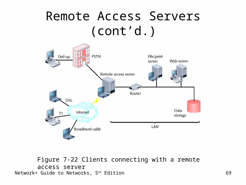
Remote Access Servers (cont’d.)
Figure 7-22 Clients connecting with a remote access server
Remote Access Protocols
• SLIP and PPP– Workstations connect using serial connection
• Encapsulate higher-layer networking protocols, in lower-layer data frames
– SLIP carries IP packets only• Harder to set up• Supports only asynchronous data
– PPP carries many different Network layer packets• Automatic set up• Performs error correction, data compression, supports
encryption• Supports asynchronous and synchronous transmission
Network+ Guide to Networks, 5th Edition 70
Network+ Guide to Networks, 5th Edition 71
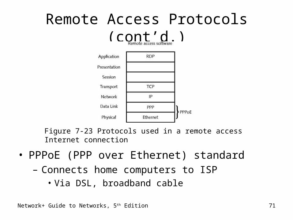
Remote Access Protocols (cont’d.)
• PPPoE (PPP over Ethernet) standard– Connects home computers to ISP
• Via DSL, broadband cable
Figure 7-23 Protocols used in a remote access Internet connection
Network+ Guide to Networks, 5th Edition 72
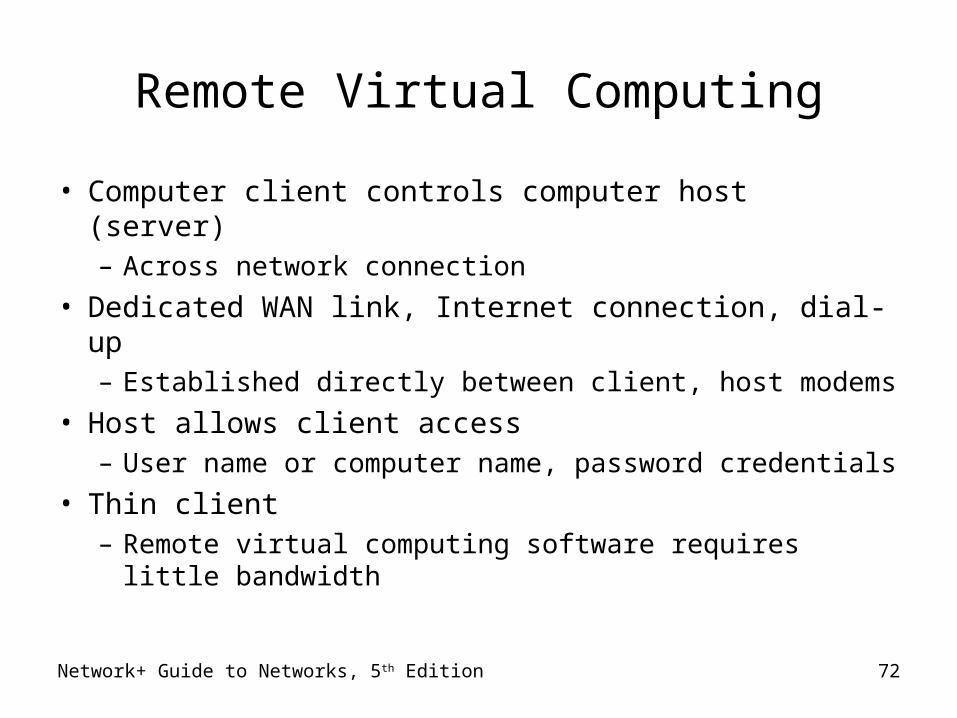
Remote Virtual Computing
• Computer client controls computer host (server)– Across network connection
• Dedicated WAN link, Internet connection, dial-up– Established directly between client, host modems
• Host allows client access– User name or computer name, password credentials
• Thin client– Remote virtual computing software requires little
bandwidth
Network+ Guide to Networks, 5th Edition 73
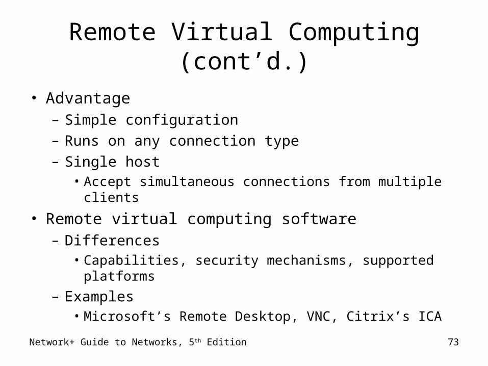
Remote Virtual Computing (cont’d.)
• Advantage– Simple configuration– Runs on any connection type– Single host
• Accept simultaneous connections from multiple clients
• Remote virtual computing software– Differences
• Capabilities, security mechanisms, supported platforms
– Examples• Microsoft’s Remote Desktop, VNC, Citrix’s ICA
Network+ Guide to Networks, 5th Edition 74
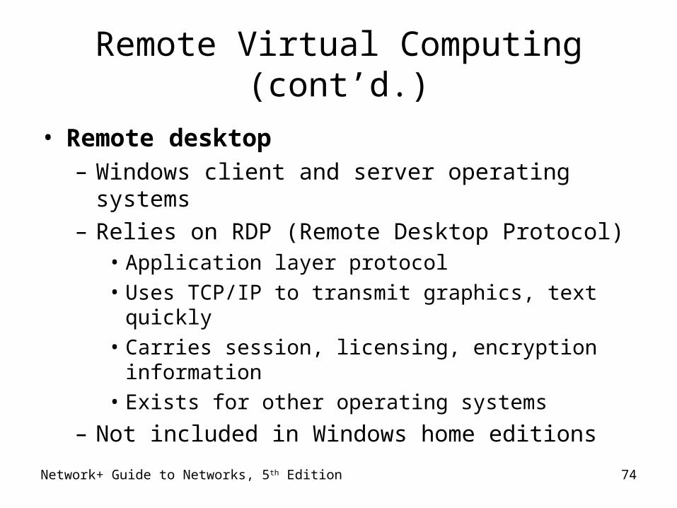
Remote Virtual Computing (cont’d.)
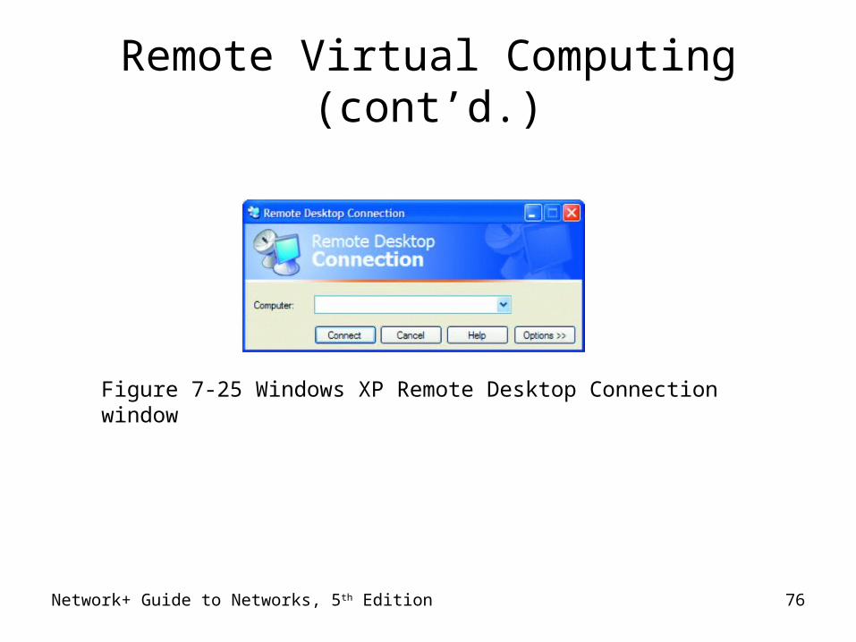
• Remote desktop– Windows client and server operating systems– Relies on RDP (Remote Desktop Protocol)
• Application layer protocol
• Uses TCP/IP to transmit graphics, text quickly
• Carries session, licensing, encryption information
• Exists for other operating systems
– Not included in Windows home editions
Network+ Guide to Networks, 5th Edition 75
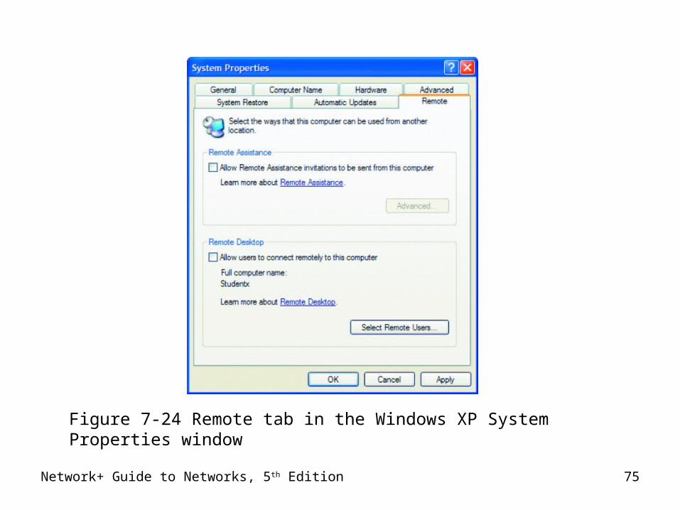
Figure 7-24 Remote tab in the Windows XP System Properties window
Network+ Guide to Networks, 5th Edition 76
Figure 7-25 Windows XP Remote Desktop Connection window
Remote Virtual Computing (cont’d.)
Network+ Guide to Networks, 5th Edition 77
Remote Virtual Computing (cont’d.)
• VNC (Virtual Network Computing)– Open source system
• One workstation remotely manipulates, receives screen updates from another workstation
• Free, anyone can modify– Protocols operate in Application layer– Advantages
• Multiple computer platform operation• Open source• Single computer supports multiple sessions
– Drawback: screen refresh rate
Network+ Guide to Networks, 5th Edition 78
Remote Virtual Computing (cont’d.)
• ICA (Independent Computing Architecture)– Citrix System’s Presentation Server
• Proprietary software
– Advantages• Ease of use
• Broad compatibility
– Disadvantages• High cost of Citrix products
• Server software configuration complexity
Network+ Guide to Networks, 5th Edition 79
VPNs (Virtual Private Networks)
• Wide area networks– Logically defined over public transmission systems
• Isolated from other public line traffic
• Software– Inexpensive– Sometimes included with other widely used software
• Tailored to customer’s distance, bandwidth needs
• Two important design considerations– Interoperability and security
Network+ Guide to Networks, 5th Edition 80
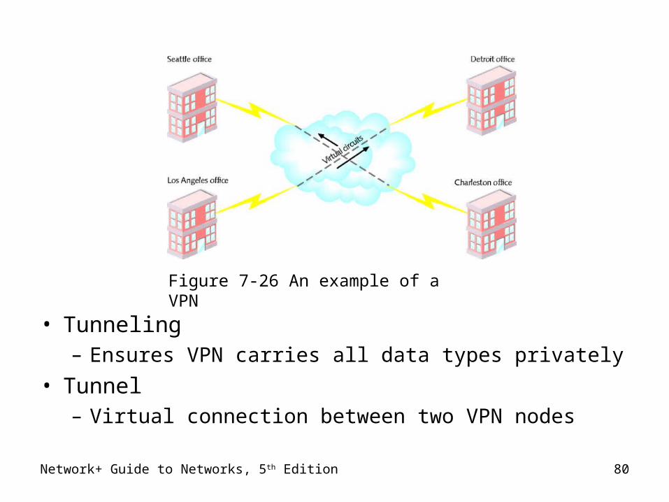
• Tunneling– Ensures VPN carries all data types privately
• Tunnel– Virtual connection between two VPN nodes
Figure 7-26 An example of a VPN
Network+ Guide to Networks, 5th Edition 81
VPNs (cont’d.)
• PPTP (Point-to-Point Tunneling Protocol)– Microsoft
• Encryption, authentication, access services– Dial directly into RRAS access server– Dial into ISP’s remote access server first
• L2TP (Layer 2 Tunneling Protocol)– Cisco
• Connects VPN using equipment mix• Connect two routers• Tunnel endpoints not on same packet-switched network
Network+ Guide to Networks, 5th Edition 82
Summary
• WAN Topologies
• PSTN and dial-up considerations
• High speed digital data transmission– Physical layer: ISDN, T-carriers, DSL, SONET– Data Link layer: X.25, frame relay, ATM– Physical and Data link: broadband
• Remote connectivity
• Remote virtual computing
• VPNs