Embed Size (px)
Citation preview
Tik-110.250 Fundamentals of Network Media, 25.1.-1.2.2001, slide 1 © Arto Karila
Tik-110.250 Fundamentals of Network Media (3 cr)Spring 2000
Network Architectures,Interconnecting Networks
Professor Arto KarilaHelsinki University of Technology
E-mail: [email protected]
Tik-110.250 Fundamentals of Network Media, 25.1.-1.2.2001, slide 2 © Arto Karila
Contents Lecture on January 25• Network architectures• ProtocolsLecture on February 1• Interconnecting networks• Internetworking
Tik-110.250 Fundamentals of Network Media, 25.1.-1.2.2001, slide 3 © Arto Karila
Network architectures • The architecture of a large system means its division into
smaller elements and the relationships between these elements
• Large and complex structures are best understood and handled by humans when divided into smaller pieces
• Telecommunication networks are among the largest and most complex systems ever designed and implemented by man, so they are best understood as structures consisting of various architectural elements
• We will start by briefly presenting layered reference models and the Internet architecture
• Networking is then discussed within this framework• The purpose is to help the student see the forest for the trees
Tik-110.250 Fundamentals of Network Media, 25.1.-1.2.2001, slide 4 © Arto Karila
Applications and the real world • People have invented various applications that use communi-
cations services, such as E-mail, WWW and digital multimedia• Applications have varying communications requirements:
• Burst/stream mode of operation• Large/small capacity requirements• Strict/loose delay requirements
• There are a number of transmission media, such as:• The ”ether”• Copper cables• Fiber optics
• These physical media suffer from limitations, such as:• Noise and interference• Attenuation• Limited bandwidth• Limited speed of signal
Tik-110.250 Fundamentals of Network Media, 25.1.-1.2.2001, slide 5 © Arto Karila
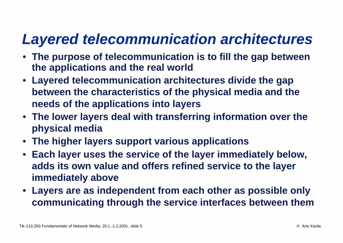
Layered telecommunication architectures • The purpose of telecommunication is to fill the gap between
the applications and the real world• Layered telecommunication architectures divide the gap
between the characteristics of the physical media and the needs of the applications into layers
• The lower layers deal with transferring information over the physical media
• The higher layers support various applications• Each layer uses the service of the layer immediately below,
adds its own value and offers refined service to the layer immediately above
• Layers are as independent from each other as possible only communicating through the service interfaces between them
Tik-110.250 Fundamentals of Network Media, 25.1.-1.2.2001, slide 6 © Arto Karila
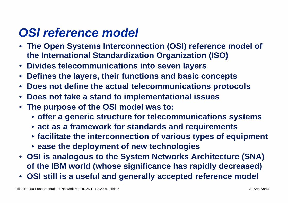
OSI reference model • The Open Systems Interconnection (OSI) reference model of
the International Standardization Organization (ISO)• Divides telecommunications into seven layers• Defines the layers, their functions and basic concepts• Does not define the actual telecommunications protocols• Does not take a stand to implementational issues• The purpose of the OSI model was to:
• offer a generic structure for telecommunications systems• act as a framework for standards and requirements• facilitate the interconnection of various types of equipment• ease the deployment of new technologies
• OSI is analogous to the System Networks Architecture (SNA) of the IBM world (whose significance has rapidly decreased)
• OSI still is a useful and generally accepted reference model
Tik-110.250 Fundamentals of Network Media, 25.1.-1.2.2001, slide 7 © Arto Karila
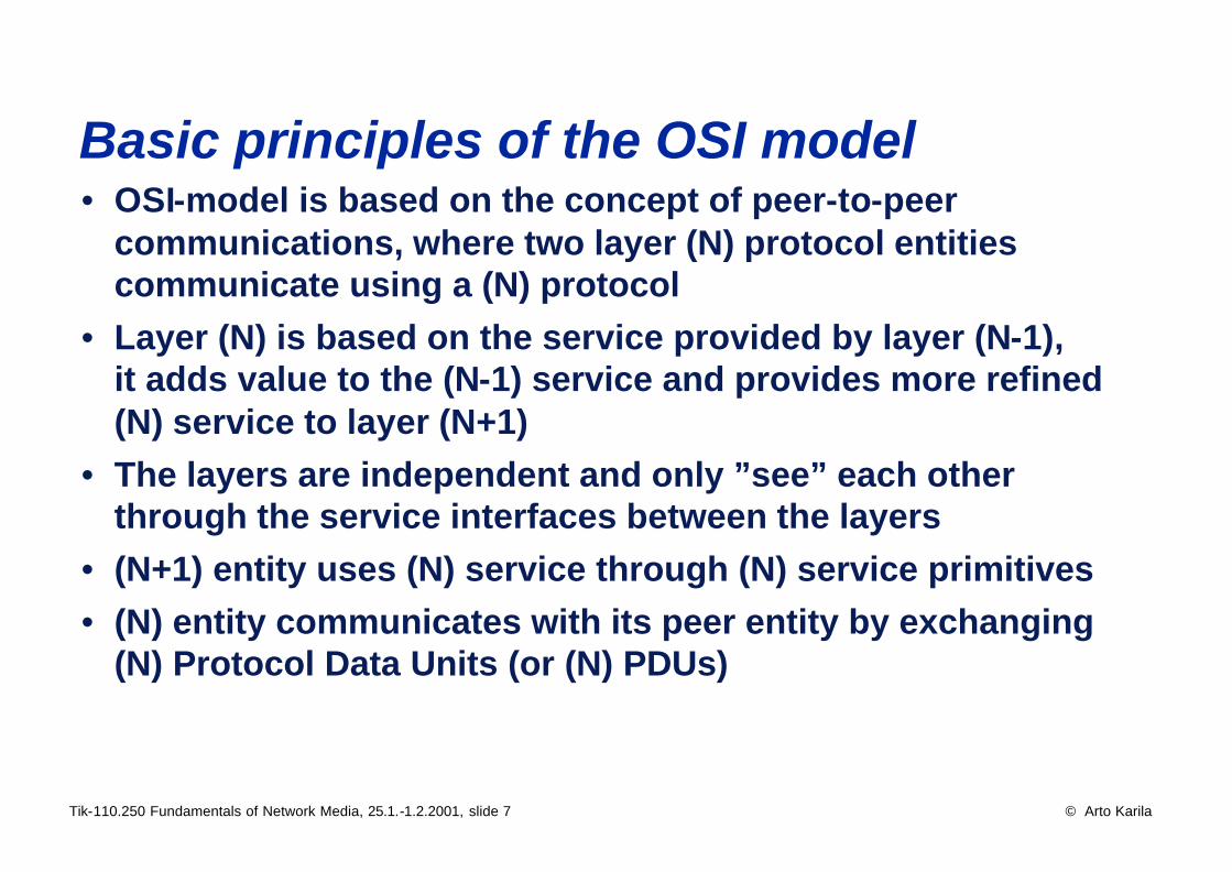
Basic principles of the OSI model • OSI-model is based on the concept of peer-to-peer
communications, where two layer (N) protocol entities communicate using a (N) protocol
• Layer (N) is based on the service provided by layer (N-1), it adds value to the (N-1) service and provides more refined (N) service to layer (N+1)
• The layers are independent and only ”see” each other through the service interfaces between the layers
• (N+1) entity uses (N) service through (N) service primitives• (N) entity communicates with its peer entity by exchanging
(N) Protocol Data Units (or (N) PDUs)
Tik-110.250 Fundamentals of Network Media, 25.1.-1.2.2001, slide 8 © Arto Karila
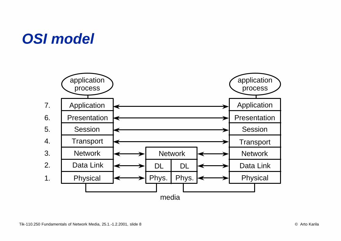
OSI model
media
Application
Presentation
Session
Transport
Network
Data Link
Physical
applicationprocess
Application
Presentation
Session
Transport
Network
Data Link
Physical
applicationprocess
Network
DL
Phys.
DL
Phys.
7.
6.
5.
4.
3.
2.
1.
Tik-110.250 Fundamentals of Network Media, 25.1.-1.2.2001, slide 9 © Arto Karila
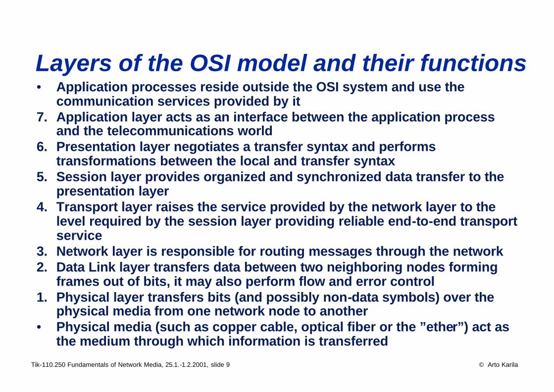
Layers of the OSI model and their functions • Application processes reside outside the OSI system and use the
communication services provided by it7. Application layer acts as an interface between the application process
and the telecommunications world6. Presentation layer negotiates a transfer syntax and performs
transformations between the local and transfer syntax5. Session layer provides organized and synchronized data transfer to the
presentation layer4. Transport layer raises the service provided by the network layer to the
level required by the session layer providing reliable end-to-end transport service
3. Network layer is responsible for routing messages through the network2. Data Link layer transfers data between two neighboring nodes forming
frames out of bits, it may also perform flow and error control1. Physical layer transfers bits (and possibly non-data symbols) over the
physical media from one network node to another• Physical media (such as copper cable, optical fiber or the ”ether”) act as
the medium through which information is transferred
Tik-110.250 Fundamentals of Network Media, 25.1.-1.2.2001, slide 10 © Arto Karila
OSI terminology • System• (N) Layer• (N) Protocol• (N) Service• (N) Connection• (N) Association• (N) Protocol Data Unit, (N)PDU• (N) Primitive• (N) Interface Data Unit, (N)-IDU• Interface Control Information, ICI• (N) Service Data Unit, (N)SDU• (N) Service Access Point, (N)SAP• Connection End-Point, CEP• CEP Identifier, CEPI
Tik-110.250 Fundamentals of Network Media, 25.1.-1.2.2001, slide 11 © Arto Karila
Critique of the OSI model • Too heavy - too many layers with overlapping functionality• Too connection oriented• Overly heavy and slow standardization process• The standards produced tend to be rather theoretical and
rarely provide solution to real-life problems• The standardization of OSI protocols (such as X.400 and
FTAM) and OSI profiles (such as GOSIP) has been a complete flop
• The main function of the OSI model today is to server as a generic framework and terminology, not as a protocol family
• The TCP/IP protocol suite has fulfilled all the promises made by OSI when it was conceived

Tik-110.250 Fundamentals of Network Media, 25.1.-1.2.2001, slide 12 © Arto Karila
General properties of protocols A protocol shall be: • Completely and unambiguously defined• Free of dead-locks and live-locks• Able to recover from all error conditions
Some possible functions of protocols:• Addressing• Connections• Error detection• Error correction• Flow control• Prioritization• Multiplexing / splitting• Segmentation / concatenation
Tik-110.250 Fundamentals of Network Media, 25.1.-1.2.2001, slide 13 © Arto Karila
Different types of network services Circuit switched services• Connect, communicate, disconnect• Fixed capacity reserved from the network for each connection• Based on Time Division Multiplexing (TDM)• E.g. the Public Switched Telecommunications Network
(PSTN) and the Nordic Public Data Network (X.21 Datex)Packet switched services• Based on virtual connections which are set up and discon-
nected but do not reserve fixed capacity from the network• Enable statistical multiplexing and more efficient use of
network capacity• E.g. X.25 type networksConnectionless (datagram) services• No connection• Each datagram is routed separately through the network• For example the Internet and most local area networks (LANs)
Tik-110.250 Fundamentals of Network Media, 25.1.-1.2.2001, slide 14 © Arto Karila
PSTN • The Public Switched Telecommunications Network (PSTN)
has developed over the past 100 years into a network with:• global coverage• high availability• well working and flexible billing system• some degree of information security• in many countries (almost) fully digitalized
• The PSTN is circuit switched• Capacity can be reserved for data (leased lines)• The network was designed for and works best with speech• Today most of the transatlantic traffic is data (mainly faxes)• Among the shortcomings of the PSTN are:
• slow standardization process• complicated signaling and network management• high cost (especially in data transfer)
Tik-110.250 Fundamentals of Network Media, 25.1.-1.2.2001, slide 15 © Arto Karila
X.25 packet networks • Compatible with the ITU-T X.25 recommendation• A packet switched international network service• Facilitates closed user groups (Virtual Private Network, VPN)• In Finland DataPak (Sonera) and DigiPak (Finnet)• Protocol layers:
• X.25 packet layer protocol• LAPB (HDLC)• X.21 (physical layer)
• A heavy protocol that does not adapt well to high transmission speeds
• Expensive and complex technology• Not well suited for LAN interconnection• Still widely used, especially in Central Europe and military
organizations
Tik-110.250 Fundamentals of Network Media, 25.1.-1.2.2001, slide 16 © Arto Karila
Frame Relay • A modern, light-weight interface to data networks• Internationally standardized (ITU-T I.233)• ”The X.25 of the 1990’s”• A connection-oriented data link layer service• Based on the same paradigms as LANs:
• Relatively high transmission speed• Reliable transmission systems => "unreliable" protocol
(that is, no acknowledgements)• Small protocol overhead
• Enables service differentiation (quality of service)• A LAN-like service in public data networks• Frame structure modified from LAPD• Detects transmission errors • No error correction• Can support a variety of physical interfaces• Mainly used at 64 kb/s to 2 Mb/s transmission speeds
Tik-110.250 Fundamentals of Network Media, 25.1.-1.2.2001, slide 17 © Arto Karila
Local Area Networks (LANs) • Local Area Network (LAN) is a fast (at least ~ Mb/s), geo-
graphically limited (~ km) digital communications network, which is owned and operated by the user organization
History of LANs• Packet radio networks (Aloha and Slotted Aloha) in Hawaii• Ethernet
• The first LAN was the early version of Ethernet in 1976, about 3 Mb/s
• Digital-Intel-Xerox “DIX” specification in 1979, 10 Mb/s• Ethernet 2 in 1982
• Token Ring• IBM Token Ring in 1985, 4 Mb/s• Later also 16 Mb/s version
• Fiber Distributed Data Interface (FDDI), 100 Mb/s• High-speed Ethernet: 100 Mb/s (FE) and 1 Gb/s (GE)
Tik-110.250 Fundamentals of Network Media, 25.1.-1.2.2001, slide 18 © Arto Karila
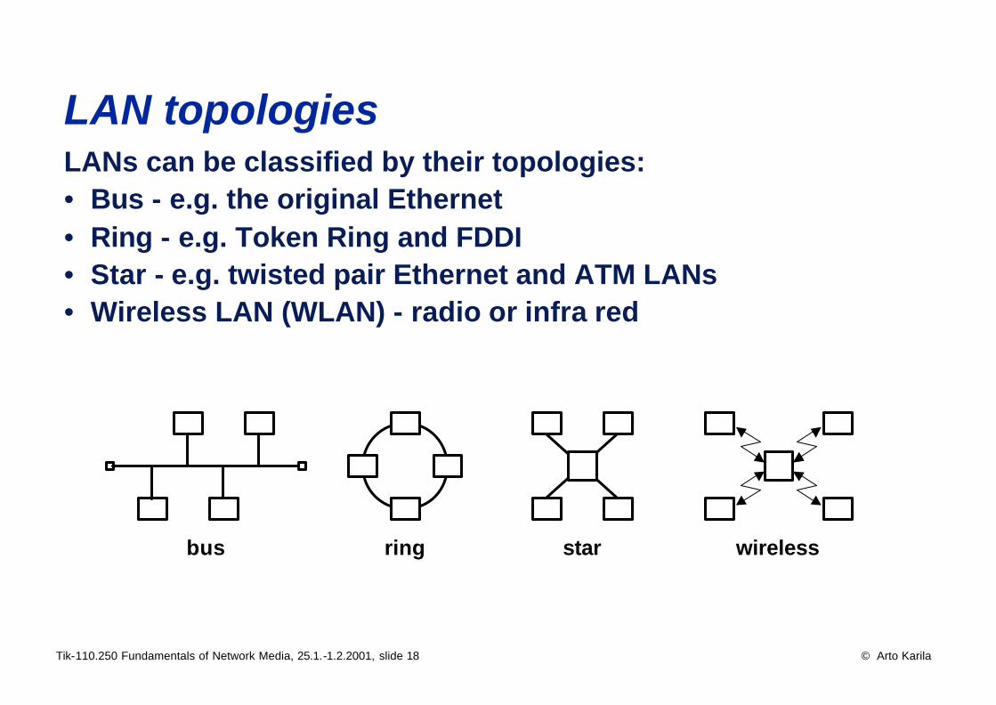
LAN topologies LANs can be classified by their topologies:• Bus - e.g. the original Ethernet• Ring - e.g. Token Ring and FDDI• Star - e.g. twisted pair Ethernet and ATM LANs• Wireless LAN (WLAN) - radio or infra red
bus ring star wireless
Tik-110.250 Fundamentals of Network Media, 25.1.-1.2.2001, slide 19 © Arto Karila
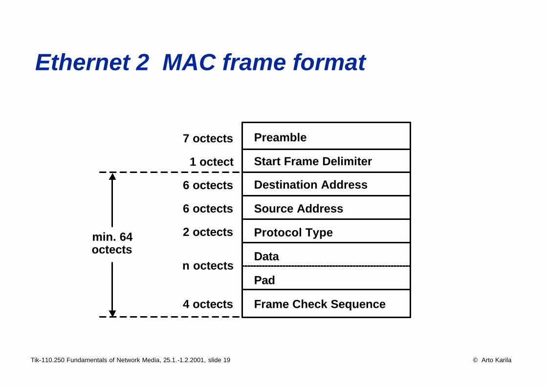
Ethernet 2 MAC frame format
Preamble
Start Frame Delimiter
Destination Address
Source Address
Protocol Type
Data
Pad
Frame Check Sequence
7 octects
1 octect
6 octects
6 octects
2 octects
4 octects
min. 64octects
n octects
Tik-110.250 Fundamentals of Network Media, 25.1.-1.2.2001, slide 20 © Arto Karila
Switched LANs • LAN switches multiply the performance of Ethernet
• In traditional Ethernet the computers of a segment share a 10 Mb/s half duplex channel
• In switched Ethernet every work station has a 10 Mb/s full-duplex channel of its own
• 100 Mb/s and 1 Gb/s Ethernet is normally switched leading into performance beating the current ATM networks
• A modern LAN Switch facilitates the interconnection of various types of LANs, such as:
• 10 Mb/s Ethernet• 100 Mb/s Ethernet• 155 Mb/s ATM (LAN Emulation) • 622 Mb/s ATM• 1 Gb/s Ethernet
Tik-110.250 Fundamentals of Network Media, 25.1.-1.2.2001, slide 21 © Arto Karila
LAN switches and VLANs • A modern LAN switch:
• 10/100 Mb/s full duplex Ethernet port per work station• 1 Gb/s Ethernet to backbone and servers• Virtual LAN (VLAN) support (IEEE 802.1Q)• Prioritization and quality of service (IEEE 802.1p etc.)• Wire-speed on all ports• Cost under $100 per work station
• Lots of products already on the market• Port and protocol based VLANs for work stations (& servers)• Tagged VLANs on trunk lines (& servers)• VLANs make it possible to define a LAN per work group
independently of geography• VLANs can be used to enhance the manageability and
security of the network and simplify routing
Tik-110.250 Fundamentals of Network Media, 25.1.-1.2.2001, slide 22 © Arto Karila
Gigabit Ethernet and its significance• Gigabit Ethernet is the most powerful off-the-shelf LAN
technology and is already priced quite competitively• Lots of products are on the market and their compatibility is
already proven• According to the standard, the maximum segment length is
550 m in multimode and 5 km in single mode fiber• Commercial products normally work up to 10 km but special
long-reach versions can work up to over 100 km• A copper version has recently arrived to the market:
• It uses all the four pairs of a UTP cable• Requires cabling that clearly exceeds Cat. 5 requirements• Especially the RJ-45 connectors used have to be of quality
• Gigabit Ethernet already is a significant network technology
Tik-110.250 Fundamentals of Network Media, 25.1.-1.2.2001, slide 23 © Arto Karila
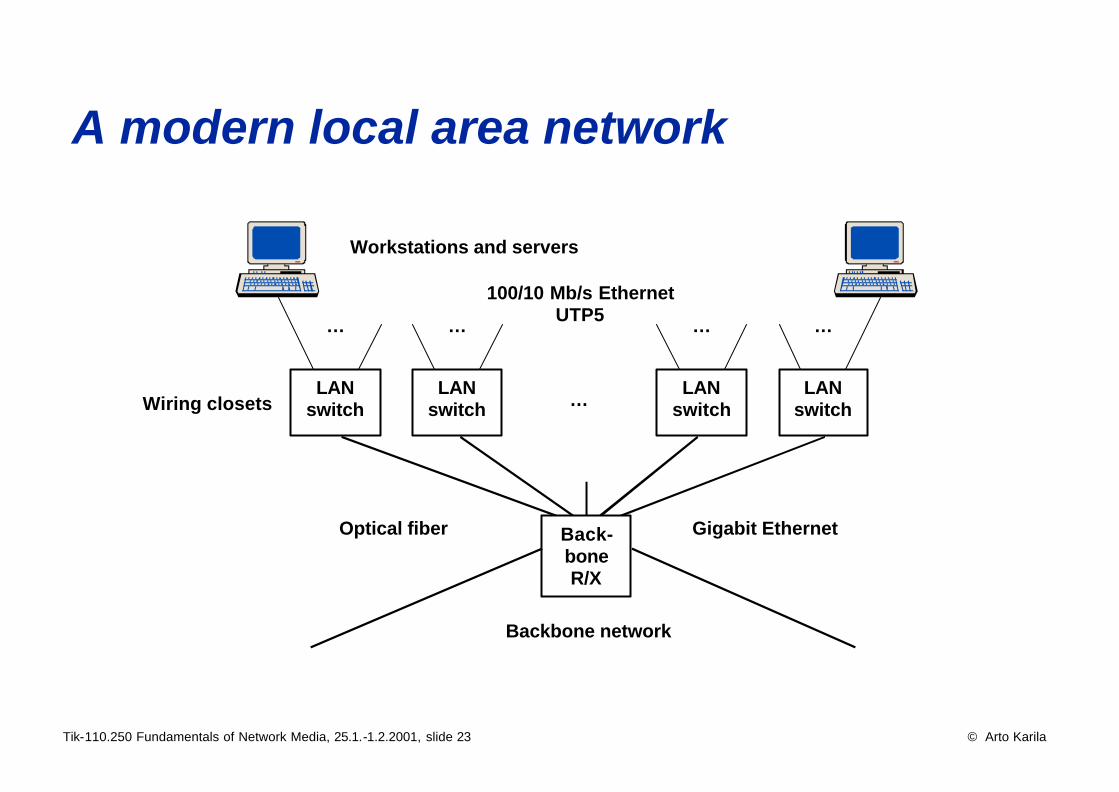
A modern local area network
100/10 Mb/s EthernetUTP5
Workstations and servers
Optical fiber
LANswitch
…
LANswitch
…
LANswitch
…
LANswitch
…
…
Gigabit EthernetBack-boneR/X
Backbone network
Wiring closets
Tik-110.250 Fundamentals of Network Media, 25.1.-1.2.2001, slide 24 © Arto Karila
In-house cabling • Cabling is the IT investment with the longest life time• Structured cabling
• One or several wiring closets on every floor• Enough space for routers and switches• Enough fiber in the backbone cabling between them• Cross connections for fibre and copper in the closets• UTP cat. 5 (currently, in the future probably something
else) cabling from the closets to the outlets (max. 90 m)• RJ-45 connectors, 4 per office desk• Adequate power outlets to the closets and office rooms
=> A network that can adapt to changing needs:• Data and telephony in the same network• Traditional LANs: Ethernet, Token Ring etc.• Fast LANs: 100 Mb/s - 1 Gb/s Ethernet• ATM 25 – 155 – 622 Mb/s
Tik-110.250 Fundamentals of Network Media, 25.1.-1.2.2001, slide 25 © Arto Karila
Wireless LANs • Wireless LANs (WLANs) appear in too configurations:
• infrastructural - wireless transmission replacing cables• ad-hoc - networks formed without prior arrangements
• Most WLANs use spread spectrum technologies:• Frequency Hopping Spread Spectrum (FHSS) - uses a
narrow-band carrier changing frequencies in a pre-defined manner known to transmitter and receiver
• Direct Sequence Spread Spectrum (DSSS) - generates a redundant bit pattern ("chip" or "chipping code") for each bit transmitted
• Spread spectrum technologies use a wider frequency band than narrow-band technologies but are more robust
• Other users of the same frequency band hear spread spectrum traffic as background noise
Tik-110.250 Fundamentals of Network Media, 25.1.-1.2.2001, slide 26 © Arto Karila
WLANs • The IEEE 802.11 WLAN standard is already widely
implemented in commercial mass products• Current products operate at 2.4 GHz frequency at 11 Mb/s• New products at 5 GHz frequency an 54 Mb/s are coming to
the market soon• 100 Mb/s and faster WLANs already operate in laboratories• Blue tooth offers limited low-cost low-capacity WLAN
technology for a variety of devices• Blue tooth’s main purpose is to replace wires in telco devices• WLANs promise high capacities at low cost within buildings• Their greatest strength is that they operate at unregulated
frequencies• Outside buildings this may also be their greatest weakness
Tik-110.250 Fundamentals of Network Media, 25.1.-1.2.2001, slide 27 © Arto Karila
ATM basics• ATM stands for Asynchronous Transfer Mode• ATM was designed as the technology of Broadband-ISDN• ATM is based on switching fixed-sized cells• ATM operates in the Data Link layer of the OSI model• Connection oriented• Small, fixed-size (53 octets) cells make hardware implementa-
tions fast, reliable and (in large quantities) inexpensive• ATM does not define the MAC or Physical layer =>
it can easily adapt to new transmission speeds and systems• The same technology in LAN, MAN and WAN =>
seamless integration of services• European ATM systems in WANs will mainly be based on
SDH (Synchronous Digital Hierarchy) infrastructure• ATM is already becoming obsolete

Tik-110.250 Fundamentals of Network Media, 25.1.-1.2.2001, slide 28 © Arto Karila
Interconnecting networks• The main trend of internetworking continues to be the
interconnection of ever faster LANs at ever higher speeds• Devices used in interconnection of networks (LANs)
• Repeater – physical layer, handles bits(and possibly non-data symbols)
• Bridge – data link layer, handles frames• Switch – data link layer, handles frames• Router – network layer, handles packets• Gateway – upper layers, used to interconnect totally
different systems (such as a DECNet-SNA gateway)• Internetworking is based on routers and network layer
addresses (IP addresses) • All the devices connected into the network must use the
same network protocol - the Internet Protocol (IP)
Tik-110.250 Fundamentals of Network Media, 25.1.-1.2.2001, slide 29 © Arto Karila
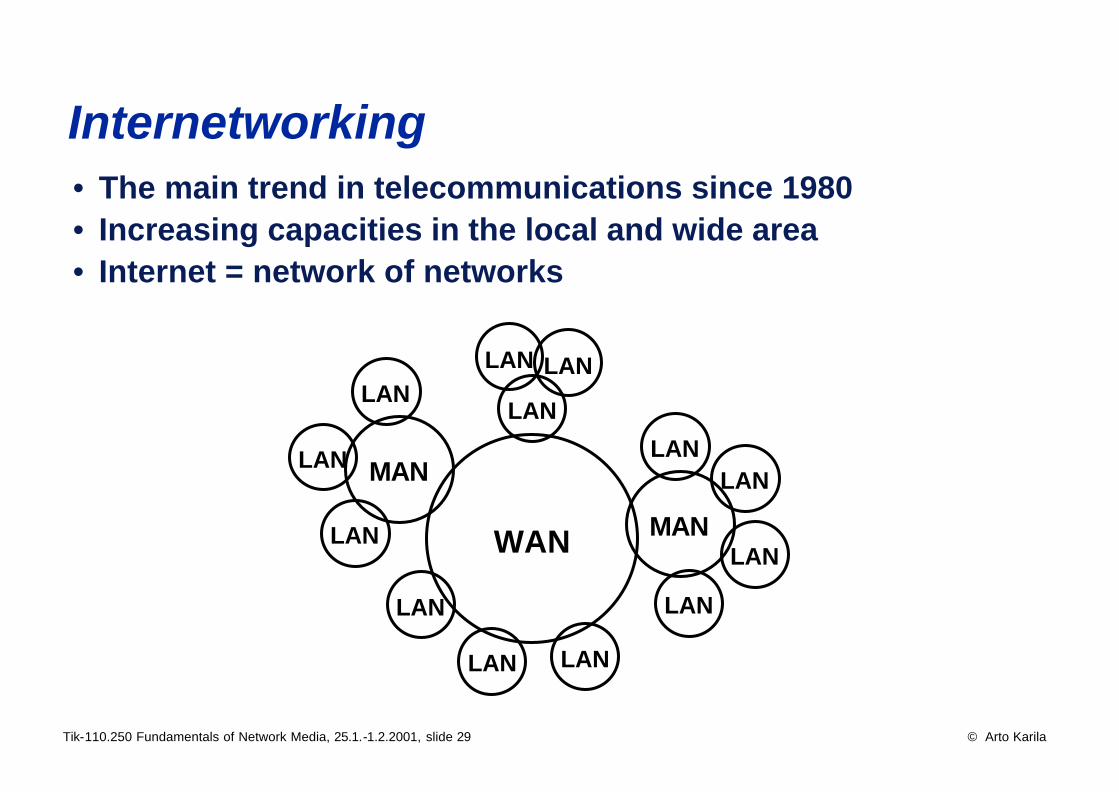
• The main trend in telecommunications since 1980• Increasing capacities in the local and wide area• Internet = network of networks
WAN
MAN
LAN
LANLAN
MAN
LAN
LAN
LAN
LAN
LAN
LAN LAN
LAN
LAN
LAN
Internetworking
Tik-110.250 Fundamentals of Network Media, 25.1.-1.2.2001, slide 30 © Arto Karila
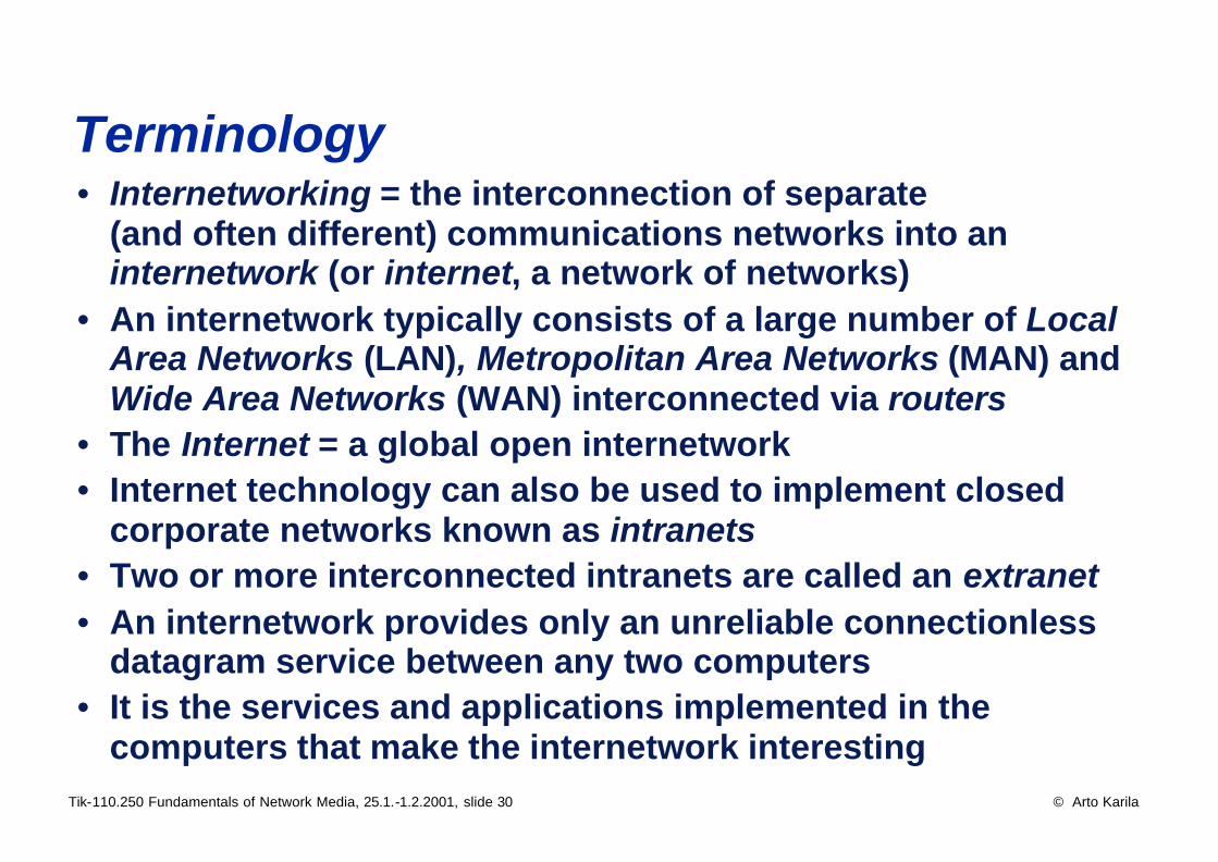
Terminology • Internetworking = the interconnection of separate
(and often different) communications networks into an internetwork (or internet, a network of networks)
• An internetwork typically consists of a large number of Local Area Networks (LAN), Metropolitan Area Networks (MAN) and Wide Area Networks (WAN) interconnected via routers
• The Internet = a global open internetwork• Internet technology can also be used to implement closed
corporate networks known as intranets• Two or more interconnected intranets are called an extranet• An internetwork provides only an unreliable connectionless
datagram service between any two computers• It is the services and applications implemented in the
computers that make the internetwork interesting
Tik-110.250 Fundamentals of Network Media, 25.1.-1.2.2001, slide 31 © Arto Karila
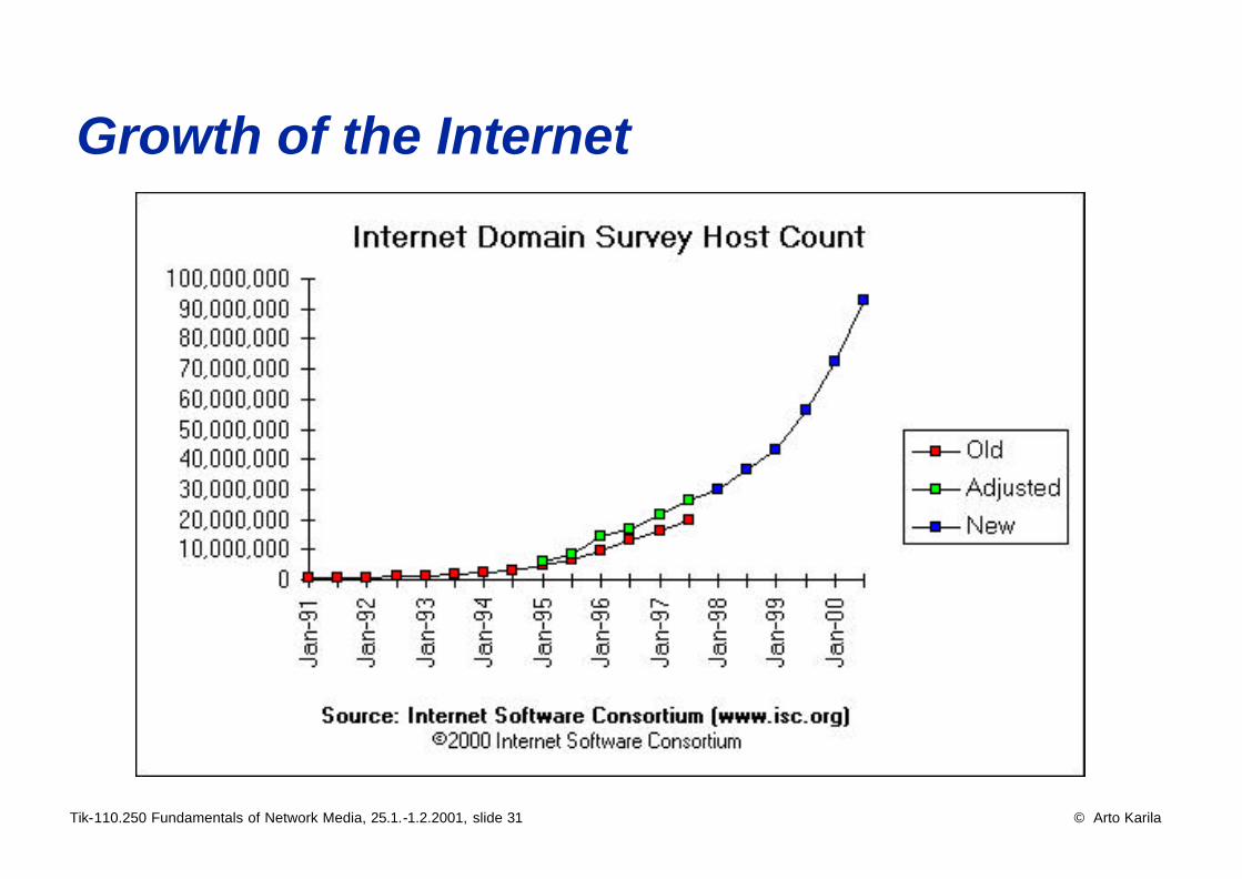
Growth of the Internet
Tik-110.250 Fundamentals of Network Media, 25.1.-1.2.2001, slide 32 © Arto Karila
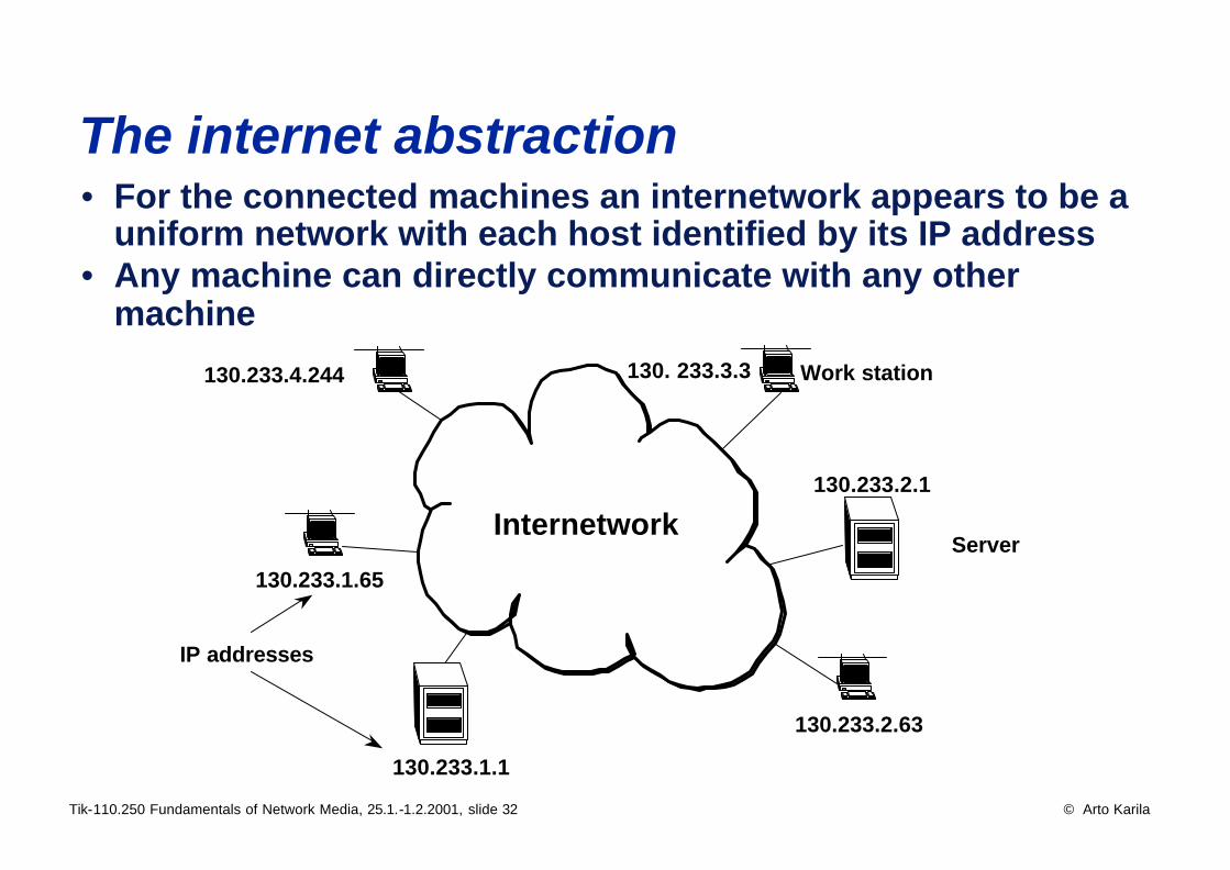
The internet abstraction • For the connected machines an internetwork appears to be a
uniform network with each host identified by its IP address• Any machine can directly communicate with any other
machine
Internetwork
Work station
Server
IP addresses
130.233.1.65
130.233.2.63
130.233.2.1
130.233.1.1
130.233.4.244 130. 233.3.3
Tik-110.250 Fundamentals of Network Media, 25.1.-1.2.2001, slide 33 © Arto Karila
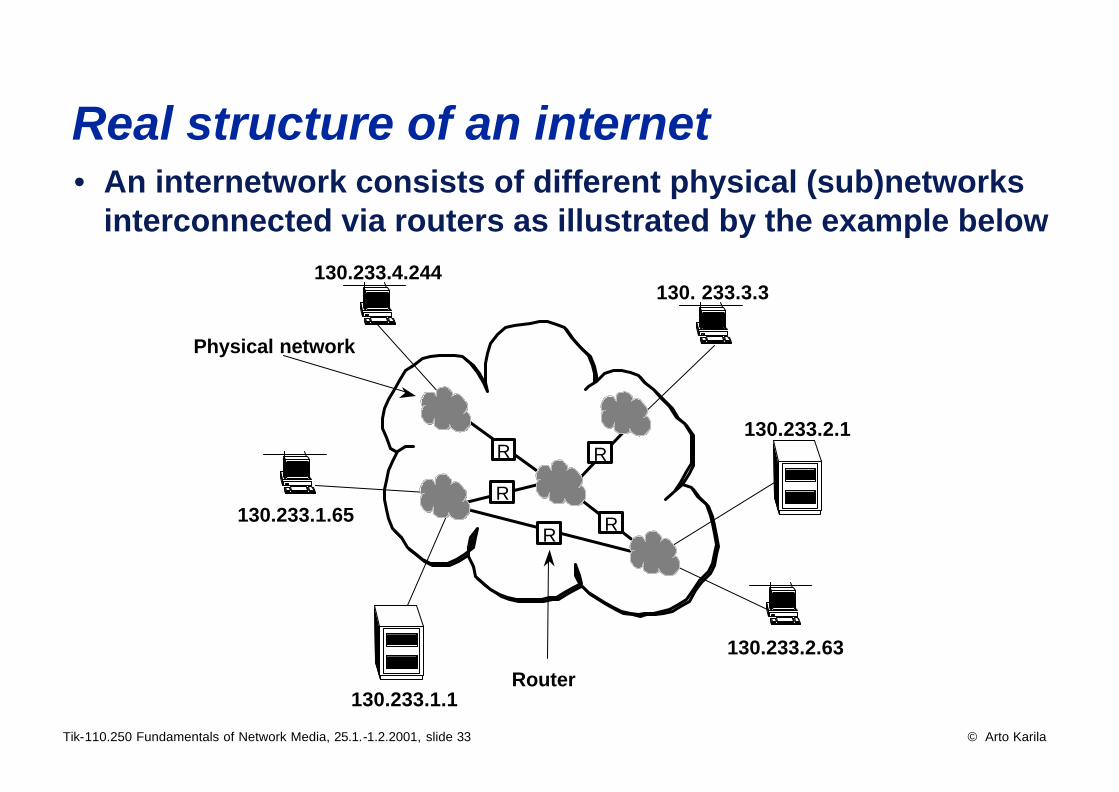
Real structure of an internet • An internetwork consists of different physical (sub)networks
interconnected via routers as illustrated by the example below
130.233.1.65
130.233.2.63
130.233.2.1
130.233.1.1
130.233.4.244130. 233.3.3
R R
RR
R
Router
Physical network
Tik-110.250 Fundamentals of Network Media, 25.1.-1.2.2001, slide 34 © Arto Karila
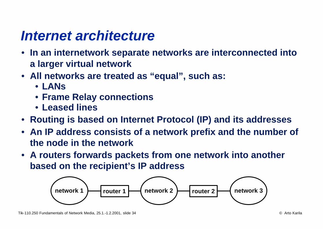
Internet architecture • In an internetwork separate networks are interconnected into
a larger virtual network• All networks are treated as “equal”, such as:
• LANs• Frame Relay connections• Leased lines
• Routing is based on Internet Protocol (IP) and its addresses• An IP address consists of a network prefix and the number of
the node in the network• A routers forwards packets from one network into another
based on the recipient’s IP address
router 1 router 2network 1 network 2 network 3
Tik-110.250 Fundamentals of Network Media, 25.1.-1.2.2001, slide 35 © Arto Karila
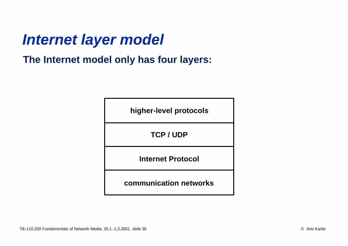
Internet layer model The Internet model only has four layers:
higher-level protocols
TCP / UDP
Internet Protocol
communication networks
Tik-110.250 Fundamentals of Network Media, 25.1.-1.2.2001, slide 36 © Arto Karila
Critique of the Internet model • No well defined terminology (inconsistencies and
ambiguities)• No clear distinction between protocols, services and
interfaces• Protocol definitions are often closely tied up with
implementational issues• Cannot describe all telecommunications systems• No distinction between physical, data link and lower part of
the network layer (just one "physical network")• Nevertheless, Internet has proved its power and continues to
be the leading network architecture• The OSI model with layers 5 and 6 combined into layer 7
can be used to discuss Internet and other protocols• In this course we will use the OSI reference model as a
generic framework for both telecom and datacom systems
Tik-110.250 Fundamentals of Network Media, 25.1.-1.2.2001, slide 37 © Arto Karila
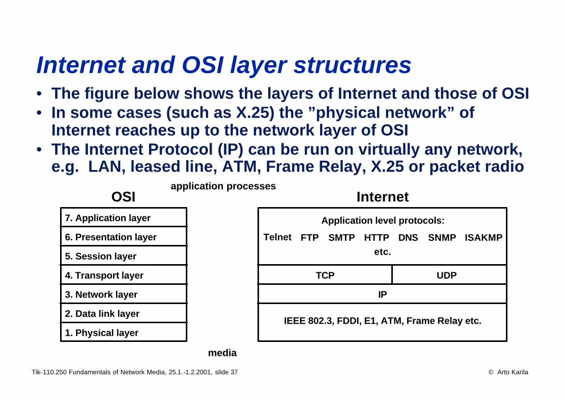
Internet and OSI layer structures • The figure below shows the layers of Internet and those of OSI• In some cases (such as X.25) the ”physical network” of
Internet reaches up to the network layer of OSI• The Internet Protocol (IP) can be run on virtually any network,
e.g. LAN, leased line, ATM, Frame Relay, X.25 or packet radio
1. Physical layer
2. Data link layer
3. Network layer
4. Transport layer
5. Session layer
6. Presentation layer
7. Application layer
IP
TCP UDP
Application level protocols:
etc.
IEEE 802.3, FDDI, E1, ATM, Frame Relay etc.
application processes
media
OSI Internet
Telnet FTP SMTP HTTP SNMPDNS ISAKMP
Tik-110.250 Fundamentals of Network Media, 25.1.-1.2.2001, slide 38 © Arto Karila
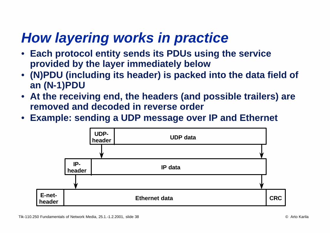
How layering works in practice • Each protocol entity sends its PDUs using the service
provided by the layer immediately below• (N)PDU (including its header) is packed into the data field of
an (N-1)PDU• At the receiving end, the headers (and possible trailers) are
removed and decoded in reverse order• Example: sending a UDP message over IP and Ethernet
UDP-header UDP data
IP-header IP data
E-net-header Ethernet data CRC
Tik-110.250 Fundamentals of Network Media, 25.1.-1.2.2001, slide 39 © Arto Karila
A brief history of the Internet • In 1957 the successful launching of the Soviet ‘Sputnik’
lead into the founding of the US Department of Defense (DoD) Defense Advanced Research Projects Agency (DARPA)
• In 1968/1969 DARPA started the development of ARPANET• The purpose was to develop an information network for the
use of the R&D projects of DoD• Telecommunications software turned out to be much larger
and more complex than anticipated• In 1974 Robert Kahn and Vinton Cerf published a paper
specifying the TCP/IP protocol• Around 1975 DARPA started the massive development of
modern internet technology• By 1979 so many scientists were involved in this work that
the Internet Control and Configuration Board (ICCB) was founded to coordinate it
Tik-110.250 Fundamentals of Network Media, 25.1.-1.2.2001, slide 40 © Arto Karila
A brief history of the Internet • In 1980 DARPA started converting their machines into TCP/IP
and ARPANET became the backbone of the new Internet• In 1981 the National Science Foundation (NSF) provided the
seed money for CSNET (Computer Science NETwork) to inter-connect the computer science departments of US universities
• In 1982 DoD defined the TCP/IP protocol as their standard• TCP/IP was included in Berkeley Unix (BSD) which was used
in about 90% of all university machines in those days• In 1985 NSF started to develop the TCP/IP based NSFNET as
an access network for its super computers• In 1986 the NSFNET backbone operated at 56 kb/s • Around 1986 commercial TCP/IP implementations started to
proliferate
Tik-110.250 Fundamentals of Network Media, 25.1.-1.2.2001, slide 41 © Arto Karila
A brief history of the Internet • In 1988 TCP/IP was specified as the preferred protocol set to
be used by the Finnish public sector (”Toimisto -90”)• In 1988 the Finnish University Network (FUNET) was con-
nected to the Internet (together with its Swedish, Norwegian and Danish counterparts) via the Nordic University Network (NORDUNET)
• In 1989 Telecom Finland (now Sonera) started its commercial IP service DataNet
• DoD had published its plans to replace TCP/IP by OSI protocols in the early 1990’s
• This lead into intensive development of OSI profiles which turned out to be a total flop
Tik-110.250 Fundamentals of Network Media, 25.1.-1.2.2001, slide 42 © Arto Karila
Recent history • In 1991 NSF lifted the restrictions on the commercial use of
the Internet• In 1991 World Wide Web (WWW) software was released by
CERN (the European Nuclear Research Center)• The Mosaic browser, developed by the National Center for
Supercomputer Applications (NCSA), was released in 1993 • In 1995 US Internet traffic was carried by commercial Internet
Service Providers (ISPs)• In 1998 the number of Internet hosts passed 50 million• Internet has established itself as the leading network
architecture that even public telco networks have to adapt to

Tik-110.250 Fundamentals of Network Media, 25.1.-1.2.2001, slide 43 © Arto Karila
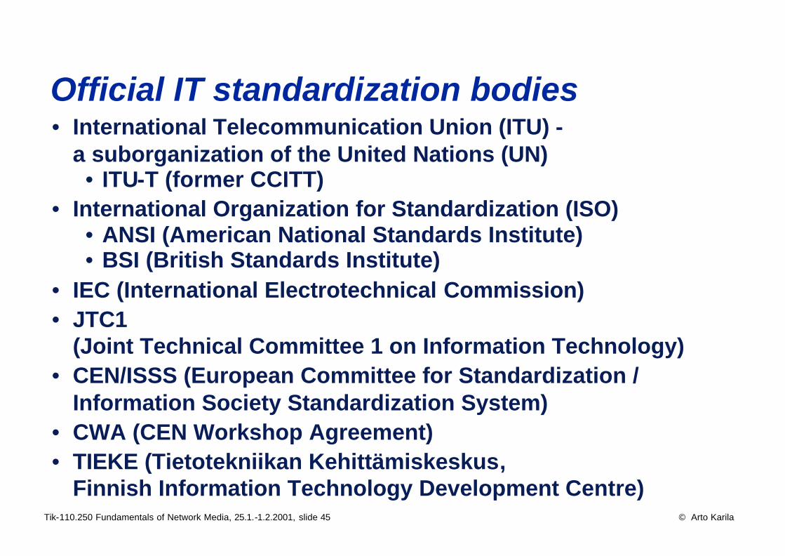
Official IT standardization bodies • International Telecommunication Union (ITU) -
a suborganization of the United Nations (UN)• ITU-T (former CCITT)
• International Organization for Standardization (ISO)• ANSI (American National Standards Institute)• BSI (British Standards Institute)
• IEC (International Electrotechnical Commission)• JTC1
(Joint Technical Committee 1 on Information Technology)• CEN/ISSS (European Committee for Standardization /
Information Society Standardization System)• CWA (CEN Workshop Agreement)• TIEKE (Tietotekniikan Kehittämiskeskus,
Finnish Information Technology Development Centre)
Tik-110.250 Fundamentals of Network Media, 25.1.-1.2.2001, slide 44 © Arto Karila
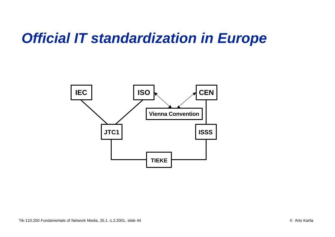
Official IT standardization in Europe
IEC ISO CEN
JTC1 ISSS
TIEKE
Vienna Convention
Tik-110.250 Fundamentals of Network Media, 25.1.-1.2.2001, slide 45 © Arto Karila
Official IT standardization bodies • International Telecommunication Union (ITU) -
a suborganization of the United Nations (UN)• ITU-T (former CCITT)
• International Organization for Standardization (ISO)• ANSI (American National Standards Institute)• BSI (British Standards Institute)
• IEC (International Electrotechnical Commission)• JTC1
(Joint Technical Committee 1 on Information Technology)• CEN/ISSS (European Committee for Standardization /
Information Society Standardization System)• CWA (CEN Workshop Agreement)• TIEKE (Tietotekniikan Kehittämiskeskus,
Finnish Information Technology Development Centre)
Tik-110.250 Fundamentals of Network Media, 25.1.-1.2.2001, slide 46 © Arto Karila
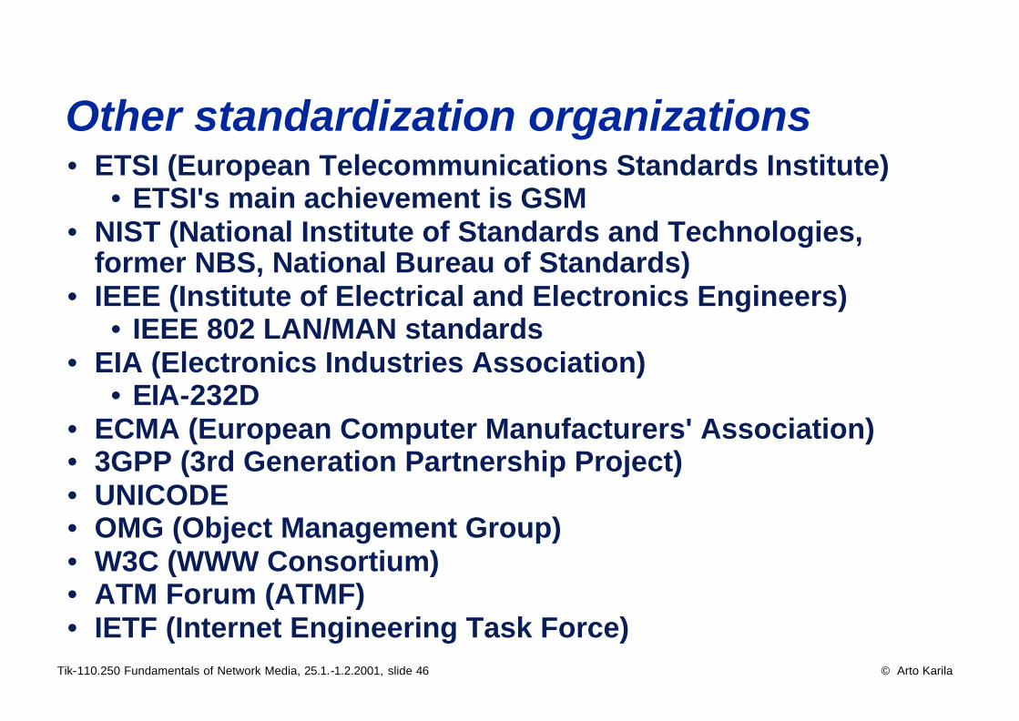
Other standardization organizations • ETSI (European Telecommunications Standards Institute)
• ETSI's main achievement is GSM• NIST (National Institute of Standards and Technologies,
former NBS, National Bureau of Standards)• IEEE (Institute of Electrical and Electronics Engineers)
• IEEE 802 LAN/MAN standards• EIA (Electronics Industries Association)
• EIA-232D• ECMA (European Computer Manufacturers' Association)• 3GPP (3rd Generation Partnership Project)• UNICODE• OMG (Object Management Group)• W3C (WWW Consortium)• ATM Forum (ATMF)• IETF (Internet Engineering Task Force)
Tik-110.250 Fundamentals of Network Media, 25.1.-1.2.2001, slide 47 © Arto Karila
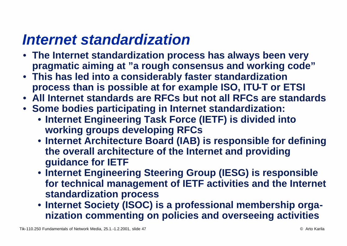
Internet standardization • The Internet standardization process has always been very
pragmatic aiming at ”a rough consensus and working code”• This has led into a considerably faster standardization
process than is possible at for example ISO, ITU-T or ETSI• All Internet standards are RFCs but not all RFCs are standards• Some bodies participating in Internet standardization:
• Internet Engineering Task Force (IETF) is divided into working groups developing RFCs
• Internet Architecture Board (IAB) is responsible for defining the overall architecture of the Internet and providing guidance for IETF
• Internet Engineering Steering Group (IESG) is responsible for technical management of IETF activities and the Internet standardization process
• Internet Society (ISOC) is a professional membership orga-nization commenting on policies and overseeing activities
Tik-110.250 Fundamentals of Network Media, 25.1.-1.2.2001, slide 48 © Arto Karila
Standards vs. de facto standards • Technological discontinuities:
• Automization and digitalization of the PSTN• Routers• Mobile phones and networks
• Networked products -the product only has value with other products
• Ever shorter technology and product cycles• Globalization of the market and increasing competition• Time to market is the key to success• Market-driven product/service development
• Choices of the market are replacing standards• “Dominant Designs” are replacing standards
(PC, Windows, intel x86, mobile phone...)• Learning together with the customer
• The role of standardization is changing