Embed Size (px)
Citation preview
NI -900 DATA SHEET
NetLinx® Controllers
NI-900 NetLinx® IntegratedController
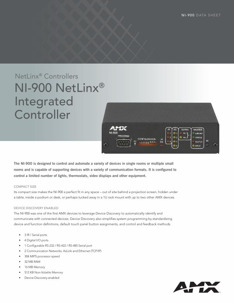
The NI-900 is designed to control and automate a variety of devices in single rooms or multiple small
rooms and is capable of supporting devices with a variety of communication formats. It is configured to
control a limited number of lights, thermostats, video displays and other equipment.
COMPACT SIZE
Its compact size makes the NI-900 a perfect fit in any space – out of site behind a projection screen, hidden under
a table, inside a podium or desk, or perhaps tucked away in a 1U rack mount with up to two other AMX devices.
DEVICE DISCOVERY ENABLED
The NI-900 was one of the first AMX devices to leverage Device Discovery to automatically identify and
communicate with connected devices. Device Discovery also simplifies system programming by standardizing
device and function definitions, default touch panel button assignments, and control and feedback methods.
• 3IR/Serialports
• 4DigitalI/Oports
• 1ConfigurableRS-232/RS-422/RS-485Serialport
• 2CommunicationNetworks:AxLinkandEthernet(TCP/IP)
• 304MIPSprocessorspeed
• 32MBRAM
• 16MBMemory
• 512KBNon-VolatileMemory
• DeviceDiscovery-enabled
NI -900 DATA SHEET
3000 RESEARCH DRIVE, R ICHARDSON, TX 75082 • 800.222.0193 • 469.624.8000 • +1.469.624.7400 • 469.624.7153 fax • www.amx.com
NI-900 (FG2105-90)
POWER300 mA @ 12 VDC
MEMORY• 64 MB SDRAM• 32 MB Compact Flash• 512 Kb of Non-volatile SRAM
ENCLOSUREMetal with black matte finish
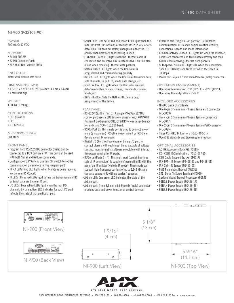
DIMENSIONS (HWD)• 1 9/16” x 5 9/16” x 5 1/8” (4 cm x 14.1 cm x 13 cm)• 1 rack unit high
WEIGHT1.30 lbs (0.59 kg)
CERTIFICATIONS• FCC (Class B)• CE• IEC 60950-1
MICROPROCESSOR304 MIPS
FRONT PANEL• Program Port: RS-232 DB9 connector (male) can be
connected to a DB9 port on a PC. This port can be used with both Serial and NetLinx commands.
• Configuration DIP Switch: Use this DIP switch to set thecommunication parameters for the Program port.
• IR RX LEDs: Red LED lights when IR data is being received via the rear IR RX port.
• IR LEDs: Three red LEDs light during the transmission of IRor Serial data via the rear IR port.
• I/O LEDs: Four yellow LEDs light when the rear I/O channels 1-4 are active. LED indicator for each I/O portreflects the state of that particular port.
• Serial LEDs: One set of red and yellow LEDs light when therear DB9 Port (1) transmits or receives RS-232, 422 or 485 data. This LED does not reflect changes in either the RTS or CTS when hardware handshaking is used.
• LINK/ACT: Green LED lights wieh the Ethernet cable is connected and an active link is established. This LED alsoblinks when receiving Ethernet data packets.
• Status: Green LED lights when the Controller is programmed and communicating properly.
• Output: Red LED lights when the Controller transmits data,sets channels On and Off, sends data strings, etc.
• Input: Yellow LED lights when the Controller receives data from button pushes, strings, commands, channellevels, etc.
• ID Pushbutton: Sets the NetLinx ID (Device only) assignment for the device.
REAR PANEL• RS-232/422/485 (Port 1): A single RS-232/422/485
control port uses a DB9 (male) connector with XON/XOFF (transmit On/transmit Off), CTS/RTS (clear to send/ready to send), and 300 - 115,200 baud.
• IR RX (Port 6): This single port is used to connect one ormore (8 maximum) IRX-SM+ swivel mount or IRX-DM+ Decora mount IR receivers.
• Digital I/O (Port 5): Four-channel binary I/O port forcontact closure with each input being capable of voltage sensing. Input format is software selectable with interac-tive power sensing for IR ports.
• IR/Serial (Ports 2 - 4): This multi-port (containing threesets of IR connectors) is capable of generating IR with the use of an IR emitter (while in IR mode). These ports can support high-frequency carriers of up to 1.142 MHz and can also generate IR with no carrier frequency.
• AxLink LED: One green LED indicates the state of theAxLink port.
• AxLink port: 4-pin 3.5 mm mini-Phoenix (male) connectorprovides data and power to external control devices.
• Ethernet port: Single RJ-45 port for 10/100 Mbps communication. LEDs show communication activity, connections, speeds and mode information.
• L/A-link/activity - Green LED lights On when the Ethernetcables are connected and terminated correctly and then blinks when receiving Ethernet data packets.
• SPD-speed - Yellow LED lights On when the connectionspeed is 100 Mbps and turns Off when the speed is 10 Mbps.
• Power port: 2-pin 3.5 mm mini-Phoenix (male) connector
OPERATING ENVIRONMENT)• Operating Temperature: 0° C (32° F) to 50° C (122° F)• Operating Humidity: 20% - 85% RH
INCLUDED ACCESSORIES• NI-900 Quick Start Guide• One 6-pin 3.5 mm mini-Phoenix female I/O connector
(41-5063)• Two 4-pin 3.5 mm mini-Phoenix female connectors
(41-5047)• One 2-pin 3.5 mm mini-Phoenix female PWR connector
(41-5025)• Three CC-NIRC IR Emitters (FG10-000-11)• OpenSSL Warranty and Licensing Information
OPTIONAL ACCESSORIES• AC-RK Accessory Rack Kit (FG515)• CC-NSER IR/Serial cables (FG10-007-10)• CSB Cable Support Bracket (FG517)• IRX-DM+ IR Sensor (FG458-10 and FG458-11)• IRX-SM+ IR Sensor (FG455-01)• PMB Pole Mount Bracket (FG531)• STS, Serial To Screw Terminal (FG959)• Surface Mount Bracket Accessory (FG525)• PSN2.8 Power Supply (FG423-17)• PSN4.4 Power Supply (FG423-45)• PSN6.5 Power Supply (FG423-41)
IR RX
AU
X
+12
V
I/O
IRIN
GN
D
4 3+12
V
IR
2 1 GN
D
ETHERNET10/100
L/A
AXlink
GN
D
AX
M
PW
R
AX
P
RS232 / 422 / 485
SPD
PWR
12VDC
SERIAL
NI-900
4
CONFIGURATIONPROGRAM
ONIRRX 3
1
2
I/OIR
INPUT
LINK/ACT
OUTPUT
STATUS
MASTER
TX
RX1
ID3
1
2
NI-900
3 2 1
5 9/16”(14.1 cm)
5 1/8”(13 cm)
1 9/16”(4 cm)
NI-900 (Front View)
NI-900 (Back View)NI-900 (Left View) NI-900 (Top View)