Embed Size (px)
Citation preview
NEMA XR 21NEMA XR 21
CHARACTERISTICS
OF AND TEST PROCEDURES FOR A
PHANTOM TO BENCHMARK CARDIAC FLUOROSCOPIC
AND FLUOROGRAPHIC
PERFORMANCE


NEMA Standards Publication XR 21-2000
Characteristics of and Test Procedures for a Phantom to Benchmark
Cardiac Fluoroscopic and Fluorographic Performance
Published by National Electrical Manufacturers Association 1300 North 17th Street, Suite 1847 Rosslyn, VA 22209 © Copyright 2000 by the National Electrical Manufacturers Association. All rights including translation into other languages, reserved under the Universal Copyright Convention, the Berne Convention for the Protection of Literary and Artistic Works, and the International and Pan American Copyright Conventions.


XR 21-2000 Page i
Table of Contents
Foreword ................................................................................................................................... iii Section 1 DESCRIPTION OF TEST ELEMENTS......................................................................................1
1.1 Overall Phantom Construction .........................................................................................1 1.1 Extended Phantoms.........................................................................................................2 1.2 Supports ...........................................................................................................................2 1.3 Alignment Tools................................................................................................................2 1.4 Visualized Field size.........................................................................................................3 1.5 Congruence of Irradiated and Visualized Fields ..............................................................3 1.6 Spatial Resolution ............................................................................................................4 1.7 Low Contrast Detectability................................................................................................4 1.8 Working Thickness Range ...............................................................................................4 1.9 Motion Blur .......................................................................................................................5 1.10 Dosimetry Adapter............................................................................................................6
Section 2 QUALIFICATIONS OF TEST OPERATORS .............................................................................7 Section 3 DRAWINGS ...............................................................................................................................9 NOTE—Sample Operating Instructions are furnished in a separate informative NEMA document.

XR 21-2000 Page ii

XR 21-2000 Page iii
Foreword
The performance of any medical imaging system can be divided into two categories: (1) Suitability of the images for the clinical procedure and (2) the amount of energy administered the patient while acquiring the images. The phantom and test procedures described here test systems under conditions simulating a range of fluoroscopically guided invasive and interventional procedures. These tools provide simultaneous objective measurements of image quality and phantom entrance dose. Test results characterize the performance of the complete system under simulated clinical conditions. All tests are performed using the imaging system configured for normal clinical use. The phantom loads the system, as does a similarly sized patient. Image quality test targets are placed at the center of the phantom (the clinically relevant region). Measurable differences in test performance may or may not reflect meaningful differences in clinical utility. Uncertainties include the variety of clinical tasks for which the equipment might be used, differences in the skills of operators, and the lack of congruence between the phantom and patient tissue. The system level tools described in this document are used to screen for inappropriate performance. Such tools are not always helpful in diagnosing the causes of such behavior. Supplementary tools can provide additional information about system or subsystem behavior. Equipment manufacturers recommend tools and procedures specific to the imaging systems that they supply. There is limited availability of optical, electronic, or digital techniques for evaluating imaging performance. Therefore, the test procedures in this standard are based on trained human observers. The FDA has reached a similar conclusion in conjunction with its mammography regulations (MQSA). NOTE—The phantom and test procedures described here were originally developed for testing imaging systems designed for invasive cardiology (23 cm image intensifier, non-subtracted images). The lateral dimensions of the phantom may be extended to accommodate different sizes and shapes of image receptors. Additional modules might be added to this standard in the future to test subtraction and other aspects of system or imaging component performance. Modules and tests not included in this standard may be used to extend test functionality. This document is scheduled for review in accordance with NEMA policy. The review process will decide whether the standard is to be withdrawn, revised, or extended for a further period. It is likely that changes in fluoroscopic technology and clinical requirements will result in the issuance of a revised standard. DISCLAIMER: The standards or guidelines presented in a NEMA standards publication are considered technically sound at the time they are approved for publication. They are not a substitute for a product seller's or user's own judgment with respect to the particular product referenced in the standard or guideline, and NEMA does not undertake to guaranty the performance of any individual manufacturer's products by virtue of this standard or guide. Thus, NEMA expressly disclaims any responsibility for damages arising from the use, application, or reliance by others on the information contained in these standards or guidelines. This standards publication was developed by the X-Ray Section. Section approval of the standard does not necessarily imply that all section members voted for its approval or participated in its development. Proposed or recommended revisions should be submitted to:
Vice President, Engineering Department National Electrical Manufacturers Association 1300 North 17th Street, Suite 1847 Rosslyn, VA 22209

XR 21-2000 Page iv
The following organizations contributed to the development of this standard: NEMA Gammex, RMI, Milwaukee, WI GE Medical Systems, Milwaukee, WI GE/Marquette Medical Systems, Milwaukee, WI Marconi Medical, Highland Heights, OH Nuclear Associates, Carle Place, NY Philips Medical Systems, Shelton, CT Quinton Imaging, Sunnyvale, CA Siemens Medical Systems, Inc., Iselin, NJ Toshiba American Medical Systems, Tustin, CA Trex/XRE, Littleton, MA SCA&I Children’s Hospital of Boston, Boston, MA The Cleveland Clinic Foundation, Dept of Cardiology, Cleveland, OH Lenox Hill Hospital, New York, NY Mayo Foundation, Division of Cardiovascular Diseases, Dept. of Diagnostic Radiology, Rochester, MN Northwestern Memorial Hospital, Radiology Dept., Chicago, IL University of Maryland Medical School, Division of Cardiology, Baltimore, MD

XR 21-2000 Page 1
Section 1 DESCRIPTION OF TEST ELEMENTS
1.1 OVERALL PHANTOM CONSTRUCTION
The basic phantom material is Plexiglas (PMMA). This material has X-ray absorption and scatter properties that are similar to soft tissue. The approximation used in this document is that the PMMA thickness is equivalent to the same path-length in the patient. Configuring the phantom to different thickness simulates the range of patient sizes and imaging projection angles The phantom’s working thicknesses of 5, 10, 20, and 30 cm correspond to PA projections through an infant, a large child or small adult, an average size adult, and a heavy adult. Angled projections have longer radiation path-lengths. Imaging systems that perform very well when tested with 20 cm of PMMA may degrade when tested with 5, 10, or 30 cm of PMMA.
The center of the phantom is placed at the isocenter of the imaging system.
The spacing between the exit surface of the phantom and the entrance surface of the image receptor is 5 cm.
The SID increases and the SSD decreases as the phantom size increases (for a conventional angiographic system).
Figure 1 OVERVIEW OF THE PHANTOM
Imaging tests are performed with the relevant test-object in the center of the phantom. The test-object (inside the phantom) is placed on the system at a position corresponding to the patient's organ of interest. (This is usually at the isocenter of an isocentric system.) These test conditions simulate normal X-ray system loading, attenuation, scatter, and imaging geometry.

XR 21-2000 Page 2
Table 1 MATERIALS AND TOLERANCES
Material
Thickness Tolerance
Comments
PMMA Plates ±1 mm
Aluminum ± 0.5 mm Type 1100
Piano Wires Commercial Steel These are "standard" items
Lead Pins ± 1 mm
Lead Plate ± 0.1 mm
Copper Plate ± 0.1 mm
Iodine ± 5% Reagent Grade Tolerance is concentration in epoxy
PC Boards Solder covered traces thick enough to be seen through 30 cm of PMMA.
1.1 EXTENDED PHANTOMS
The lateral dimensions and shape of test plates may exceed those shown in the drawings. Extensions shall be made of the same materials as the relevant test plates. Phantoms complying with this standard shall contain all of the test elements described below. Phantoms may incorporate additional features. The manufacturers of extended phantoms shall demonstrate that additional features do not degrade the functionality of the basic tests described here. 1.2 SUPPORTS
Two supports are included in the specification. These are the "small base" and the "test stand." All of the required tests can be performed with either support. Locally supplied shims are needed to adapt either support to a curved tabletop. 1.3 ALIGNMENT TOOLS
The field size plate is placed on top of the phantom. A second plate with a centered radiopaque dot is placed in the base. The imaging gantry is adjusted until the cross wires intersect the approximate center of the disk (Figure 2).

XR 21-2000 Page 3
Perfect Acceptable Unacceptable
Figure 2 ALIGNMENT TOOLS: RADIOGRAPH AND SCHEMATIC DRAWING
1.4 VISUALIZED FIELD SIZE
Plate 08 is placed on the entrance surface of the image receptor. The plate is fluorographed to determine the actual FOV. 1.5 CONGRUENCE OF IRRADIATED AND VISUALIZED FIELDS
This test is not needed if the shutters are fully seen in the FOV under test. (CAUTION: Digitally synthesized shutters may simulate this effect without actual beam collimation.) The test is performed by placing Plate 08 at the isocenter. The SID is set to a convenient distance (e.g. 100 cm). A radiographic film is placed on the entrance surface of the image receptor (Figure 3). The size of the visualized field is recorded fluorographically. The size of the irradiated field is determined by inspection of the processed radiographic film. The magnification of the scale on the test plate is also obtained by inspection of the radiographic film. The test may be done in any orientation of the beam.
Figure 3 CONGRUENCE TEST
ImageReceptor
X-RayTube
Test Plate atIsocenter
RadiographicFilm
Irradiated Field
Visualized Field
SAD
SID
Congruence TestRevised 6 Feb 00 SB

XR 21-2000 Page 4
1.6 SPATIAL RESOLUTION
A standard lead bar pattern (Nuclear Associates Model # 07-538 or equivalent) is contained in the central plate (01). The discrete bars on the plate are oriented at 45 degrees to the video or digital lines. This minimizes the effects of aliasing and moiré patterns on the observations. A photograph and radiograph of the active portion of this plate are shown in Figure 4.
H – Air cylinder
C – Air ‘test pin’
E – Lead test pin
J – Aluminum cylinder
Figure 4
PHOTOGRAPH AND RADIOGRAPH OF THE CENTRAL TEST PLATE
1.7 LOW CONTRAST DETECTABILITY
A series of holes with different diameters and thicknesses is drilled in the central plate. These holes are filled with elemental iodine dispersed in epoxy. The relative areal concentrations of iodine in the four patterns are 200, 100, 50, and 25 mg/cc. These targets are shown in Figure 5. Note: Additional large iodine targets are provided at the margins of the central plate. These are used to assure the correct areal density of iodine in the patterns described above. 1.8 WORKING THICKNESS RANGE
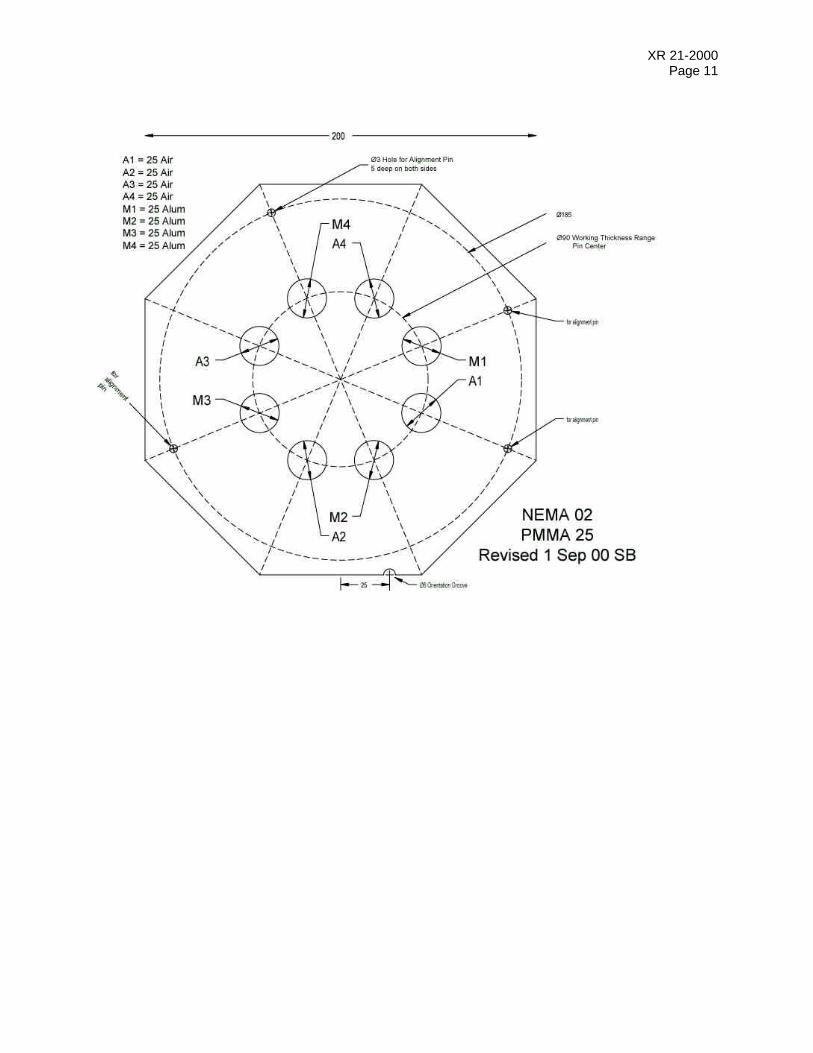
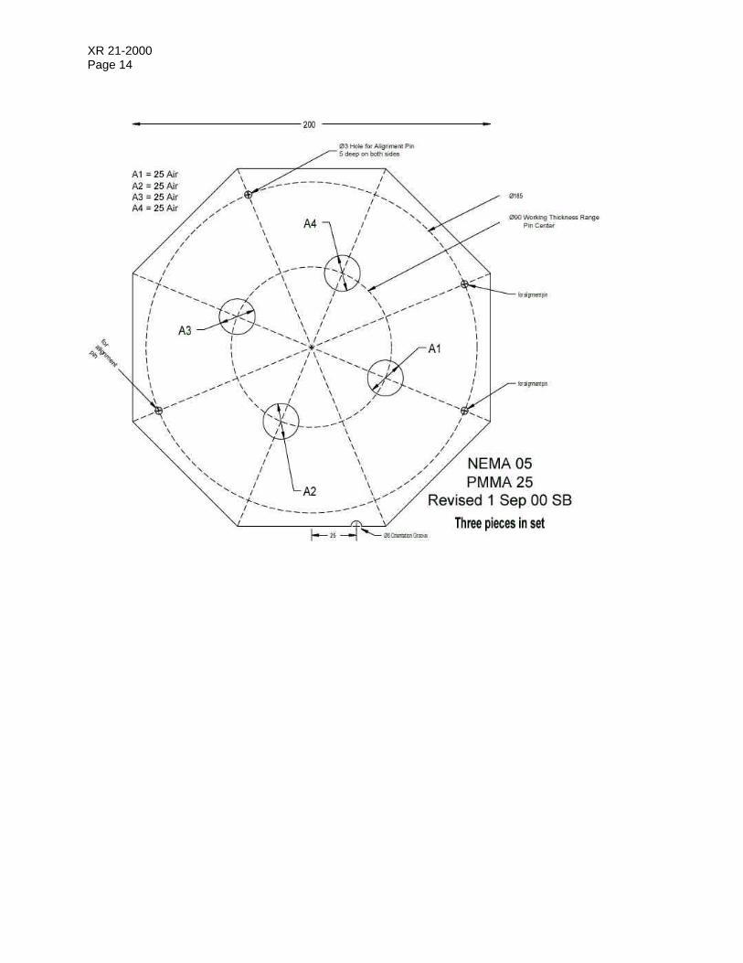
Video and digital signals may be either white or black clipped. The working thickness range tool provides a measure of this effect. Aluminum is used as a bone substitute for this test. Air is used as the target for the air columns. Lead is used as the target for the aluminum columns. A column is resolved if the target can be seen within the column (Figure 5). The specifications for each the columns are given in Table 2. This design provides four aluminum thicknesses for the 10 and 20 cm configuration. There are four different air thicknesses available for the 20 cm configuration and three different air thicknesses available for 10 cm configuration. These steps, plus a pure PMMA region of the phantom, may be used as a gray scale tool.

XR 21-2000 Page 5
This is an illustration, not a radiograph
Figure 5
WORKING THICKNESS RANGE APPEARANCE
Table 2 CONTENTS OF WORKING THICKNESS RANGE CYLINDERS
(200 mm Total Thickness Phantom)
A1 A2 A3 A4 M1 M2 M3 M4
Material mm of the specified material
Air 175 150 125 100 -- -- -- --
Aluminum -- -- -- -- 40 47 53 60
PMMA 25 50 75 100 160 153 147 140
Plate 01 N/A N/A N/A N/A N/A N/A N/A N/A
Plate 02 25 25 25 25 25 25 25 25
Plate 03 25 25 25 -- -- -- 3 10
Plate 04 25 25 -- -- 15 22 25 25
Plate 05 (3 pieces) 25 25 25 25 -- -- -- --
Plate 06 25 -- -- -- -- -- -- --
Plate 07 (5 pieces) -- -- -- -- -- -- -- --
Contents of working thickness range cylinders plates 1-4 (100 mm total thickness phantom) Air or Aluminum 75 75 50 25 40 47 53 60 NOTE—This configuration provides optional use of the WTR test in the 20 cm configuration. 1.9 MOTION BLUR
A rotating spoke target allows visual evaluation of motion unsharpness and the effects of temporal averaging. The device contains five steel piano wires of different diameters (0.022, 0.016, 0.012, 0.009, and 0.005 inches).
Notes 1 There is too much variability in the construction of commercial angiographic guide wires to designate "standard" wires for this phantom. 2 The convention is to label angiographic guide wires in decimal inches.

XR 21-2000 Page 6
The plane of the wires is placed at isocenter of the imaging system. (The rotating spoke assembly (13) replaces the central test plate (01) when it is used.)
The drive motor is out of the fluorographic field of view.
The fluorographic image on the right shows video lag and a small degree of motion unsharpness.
Figure 6
ROTATING SPOKE DEVICE AT ISOCENTER 1.10 DOSIMETRY ADAPTER
Dosimetry adapters allow measurement of the phantom entrance exposure (rate) at a standardized position in front of the entrance surface of the phantom (25 mm). The reading includes scatter from the phantom and an increase in reading because the measuring point is closer to the source than the entrance surface of the phantom.
The central test plate (01) may be replaced with a blank plate (07) in the 5, 10, 20, and 30 cm configurations to remove the effect of the lead resolution plate on phantom entrance dose.
The system may be optionally configured (including the 3 mm lead plate if necessary) to assess maximum fluoroscopic dose rate at 30 cm from the image receptor. The results will be somewhat higher than "in-air" measurements due to back-scatter from the phantom.
Dosimeter center is always 25 mm below bottom of phantom
Figure 7 TYPICAL DOSIMETRY MEASUREMENTS GEOMETRY

XR 21-2000 Page 7
Section 2
QUALIFICATIONS OF TEST OPERATORS
The consistency of these tests between operators is dependent on the skill and training of the test operator. The tester should participate in a formal training program before working independently. This is similar to the requirement for MQSA (mammography) testers.

XR 21-2000 Page 8
Table 3 PARTS LIST
1 each 01 Central target assembly 1 each 02 WTR plate A 1 each 03 WTR plate B 1 each 04 WTR plate C 3 each 05 WTR plate D 1 each 06 WTR plate E 4 each 07 Blank plate with alignment parts 1 each 08 Field size plate 1 each 09 Alignment target for test stand 1 each 10 Alignment cross for test stand 1 each 11 Alignment target for small base 1 each 12 Alignment cross for small base 1 each 13 Rotating target assembly 1 each 14 Test stand 1 each 15 Small base 1 each 16 3 mm thick lead plate with laminate (may be fabricated using layers of Pb) 1 each 17 2 mm thick copper plate with laminate (may be fabricated using layers of Cu) 100 each -- Alignment pins (includes spares) OPTIONAL Dosimeter alignment adapter (differs for different probe types)

XR 21-2000 Page 9
Section 3 DRAWINGS
Plate Identification and Stacking Order Rotating Assembly (13) is not shown. It replaces plate (01) when it is used. Base and Test Stand are not shown.

XR 21-2000 Page 10
XR 21-2000 Page 11

XR 21-2000 Page 12

XR 21-2000 Page 13
XR 21-2000 Page 14

XR 21-2000 Page 15

XR 21-2000 Page 16

XR 21-2000 Page 17

XR 21-2000 Page 18

XR 21-2000 Page 19
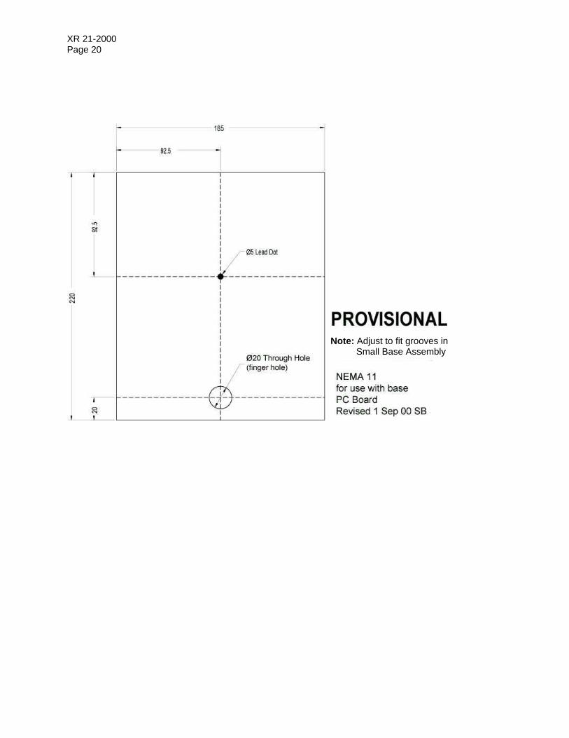
XR 21-2000 Page 20
Note: Adjust to fit grooves in Small Base Assembly

XR 21-2000 Page 21

XR 21-2000 Page 22

XR 21-2000 Page 23

XR 21-2000 Page 24

XR 21-2000 Page 25

XR 21-2000 Page 26