Embed Size (px)
Citation preview
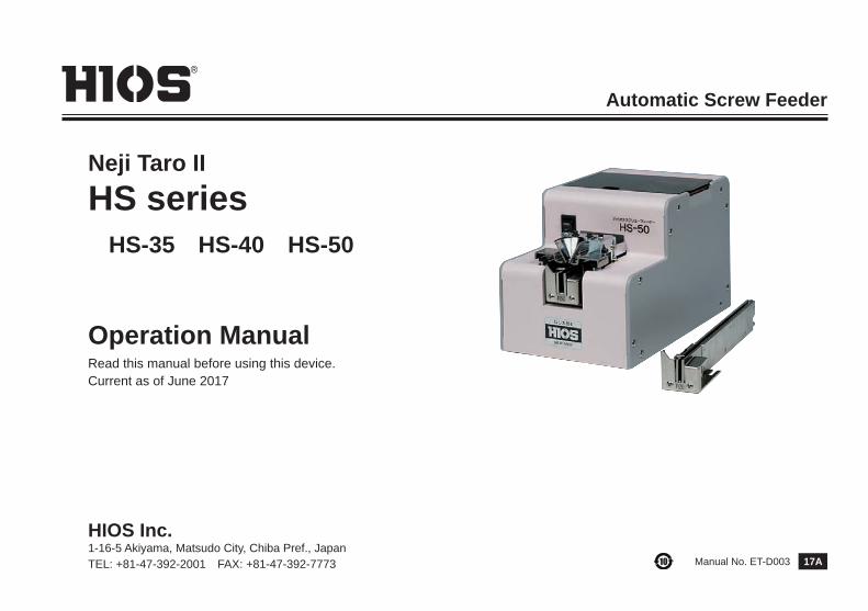
Automatic Screw Feeder
Neji Taro IIHS series HS-35 HS-40 HS-50
Operation ManualRead this manual before using this device.Current as of June 2017
17AManual No. ET-D003
HIOS Inc. 1-16-5 Akiyama, Matsudo City, Chiba Pref., JapanTEL: +81-47-392-2001 FAX: +81-47-392-7773
- 1 -
1.Before UseThank you for purchasing the NJ Series Automatic Screw Feeder. Before using this machine, please make sure thatthe following accessories are supplied with the machine.Accessories Operation manual x 1 AC adapter x 1 Allen wrench x 1 Screwdriver x 1※ For products purchased outside of Japan, no adapters will be supplied with the machine.Please purchase separate adapter with equivalent output specification as required.To obtain optimum performance from this machine, it is essential that you thoroughly read this manual2. Important safety instructions
(1) Be sure to keep the feeder away from flammable or explosive gases, heat sources, humidity, static electricity and direct sunlight. Do not use the feeder if the above are present.(2) Set the feeder on a flat and stable place. Otherwise it may fall and cause injuries.(3) Unplug the AC adapter from the electric outlet after use or when the feeder is not used for a long time.(4) Use only the AC adapter supplied with the feeder.(5) Never insert fingers or the objects in the screw bin, the access holes or other open spaces.(6) In case of malfunction, turn off the power and unplug the AC adapter. Continuing to use a malfunctioning feeder may cause fire, electric shock or injury. Contact the dealer you bought it from. (7) Do not scratch the rail or allow oil to get on it.(8) Use only the recommended screws.(9) Do not use excess force when removing screws.(10) Do not use screws covered with oil or dust.CAUTION: Do not attempt to repair, disassemble or modify the feeder by yourself.Consult your dealer for assistance.
Contents1. Before Use・・・・・・・・・・・・・・・・・・・・・・・・・・・・・・・・ 12. Important safety instructions・・・・・・・・・・・・・・・・・ 13. Parts of Names・・・・・・・・・・・・・・・・・・・・・・・・・・・・ 24. Checks and Adjustments before Operation・・・・ 3
5. Operating Procedures and Operational Checks・・・・ 7 6. Trouble Shooting・・・・・・・・・・・・・・・・・・・・・・・・・・・・・・ 11 7. Maintenance・・・・・・・・・・・・・・・・・・・・・・・・・・・・・・・・ 14 8. Specifications・・・・・・・・・・・・・・・・・・・・・・・・・・・・・・・・ 16 9. External Diagram・・・・・・・・・・・・・・・・・・・・・・・・・・・・・ 18 10. The following table is for China RoHS2・・・・・・・・・・ 19
- 2 -
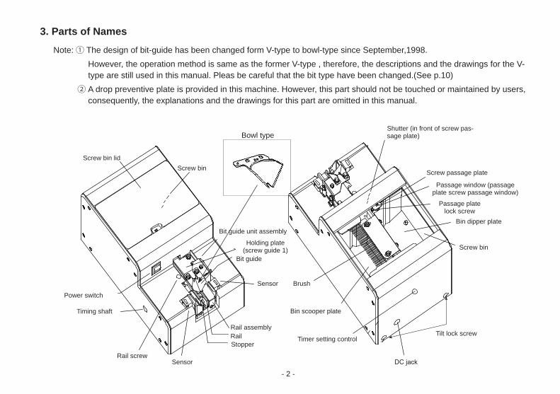
3. Parts of NamesNote:① The design of bit-guide has been changed form V-type to bowl-type since September,1998.
However, the operation method is same as the former V-type , therefore, the descriptions and the drawings for the V-type are still used in this manual. Pleas be careful that the bit type have been changed.(See p.10)
② A drop preventive plate is provided in this machine. However, this part should not be touched or maintained by users, consequently, the explanations and the drawings for this part are omitted in this manual.
Screw bin lid
Power switch
Timing shaft
Rail screw
StopperRailRail assembly
Sensor
Sensor
Brush
Timer setting control Tilt lock screw
Bin dipper plate
Screw passage plate
Shutter (in front of screw pas-sage plate)
Screw bin
DC jack
Bin scooper plate
Bit guide
Holding plate(screw guide 1)
Bit guide unit assembly
Screw bin
Bowl type
Passage window (passage plate screw passage window)
Passage plate lock screw
- 3 -
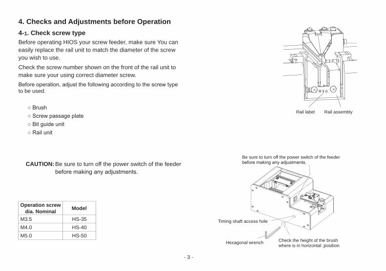
4. Checks and Adjustments before Operation4-1. Check screw typeBefore operating HIOS your screw feeder, make sure You can easily replace the rail unit to match the diameter of the screw you wish to use.Check the screw number shown on the front of the rail unit to make sure your using correct diameter screw.Before operation, adjust the following according to the screw type to be used.
○ Brush○ Screw passage plate○ Bit guide unit○ Rail unit
CAUTION: Be sure to turn off the power switch of the feeder before making any adjustments.
Operation screw dia. Nominal Model
M3.5 HS-35M4.0 HS-40M5.0 HS-50
R 3 0
Rail label
Be sure to turn off the power switch of the feeder before making any adjustments.
Check the height of the brush where is in horizontal ;positionHexagonal wrench
Timing shaft access hole
Rail assembly
- 4 -
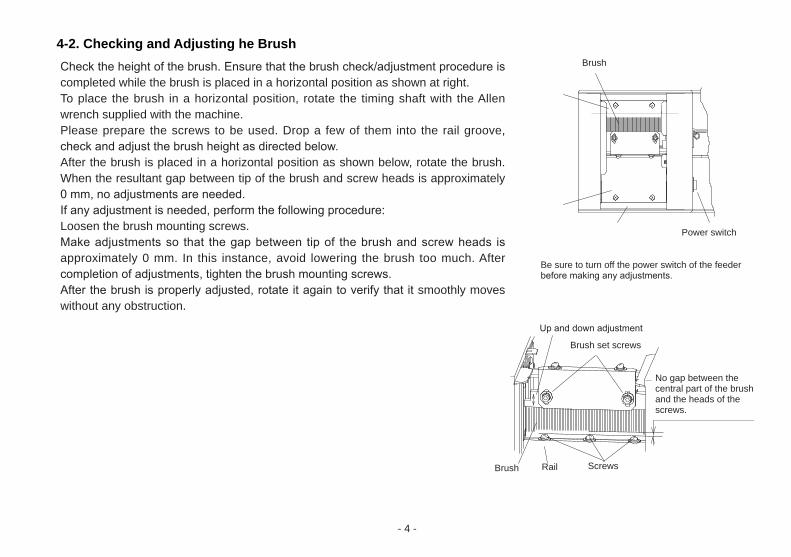
Be sure to turn off the power switch of the feeder before making any adjustments.
4-2. Checking and Adjusting he BrushCheck the height of the brush. Ensure that the brush check/adjustment procedure is completed while the brush is placed in a horizontal position as shown at right. To place the brush in a horizontal position, rotate the timing shaft with the Allen wrench supplied with the machine.Please prepare the screws to be used. Drop a few of them into the rail groove, check and adjust the brush height as directed below.After the brush is placed in a horizontal position as shown below, rotate the brush. When the resultant gap between tip of the brush and screw heads is approximately 0 mm, no adjustments are needed.If any adjustment is needed, perform the following procedure:Loosen the brush mounting screws.Make adjustments so that the gap between tip of the brush and screw heads is approximately 0 mm. In this instance, avoid lowering the brush too much. After completion of adjustments, tighten the brush mounting screws.After the brush is properly adjusted, rotate it again to verify that it smoothly moves without any obstruction.
Up and down adjustment
Brush set screws
ScrewsBrush
Brush
Rail
No gap between the central part of the brush and the heads of the screws.
Power switch
- 5 -
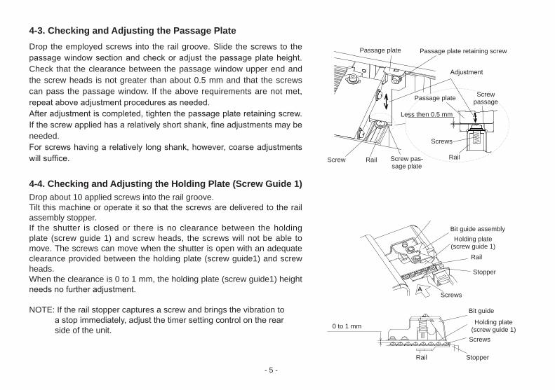
4-3. Checking and Adjusting the Passage PlateDrop the employed screws into the rail groove. Slide the screws to the passage window section and check or adjust the passage plate height. Check that the clearance between the passage window upper end and the screw heads is not greater than about 0.5 mm and that the screws can pass the passage window. If the above requirements are not met, repeat above adjustment procedures as needed.After adjustment is completed, tighten the passage plate retaining screw. If the screw applied has a relatively short shank, fine adjustments may be needed. For screws having a relatively long shank, however, coarse adjustments will suffice.
4-4. Checking and Adjusting the Holding Plate (Screw Guide 1)Drop about 10 applied screws into the rail groove.Tilt this machine or operate it so that the screws are delivered to the rail assembly stopper.If the shutter is closed or there is no clearance between the holding plate (screw guide 1) and screw heads, the screws will not be able to move. The screws can move when the shutter is open with an adequate clearance provided between the holding plate (screw guide1) and screw heads.When the clearance is 0 to 1 mm, the holding plate (screw guide1) height needs no further adjustment.
NOTE: If the rail stopper captures a screw and brings the vibration to a stop immediately, adjust the timer setting control on the rear side of the unit.
A
Passage plate
Passage plate
Less then 0.5 mm
Screw
Screws
Screws
Screws
Rail Rail
Rail
Rail
Stopper
Stopper
Screw pas-sage plate
Adjustment
Bit guide assembly
Bit guide
Holding plate(screw guide 1)
Holding plate(screw guide 1)0 to 1 mm
Screwpassage
Passage plate retaining screw
- 6 -
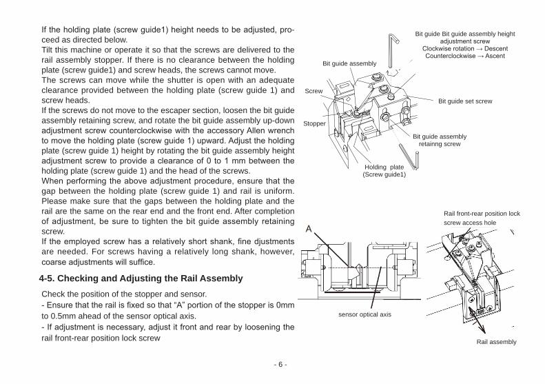
If the holding plate (screw guide1) height needs to be adjusted, pro-ceed as directed below.Tilt this machine or operate it so that the screws are delivered to the rail assembly stopper. If there is no clearance between the holding plate (screw guide1) and screw heads, the screws cannot move. The screws can move while the shutter is open with an adequate clearance provided between the holding plate (screw guide 1) and screw heads.If the screws do not move to the escaper section, loosen the bit guide assembly retaining screw, and rotate the bit guide assembly up-down adjustment screw counterclockwise with the accessory Allen wrench to move the holding plate (screw guide 1) upward. Adjust the holding plate (screw guide 1) height by rotating the bit guide assembly height adjustment screw to provide a clearance of 0 to 1 mm between the holding plate (screw guide 1) and the head of the screws.When performing the above adjustment procedure, ensure that the gap between the holding plate (screw guide 1) and rail is uniform. Please make sure that the gaps between the holding plate and the rail are the same on the rear end and the front end. After completion of adjustment, be sure to tighten the bit guide assembly retaining screw.If the employed screw has a relatively short shank, fine djustments are needed. For screws having a relatively long shank, however, coarse adjustments will suffice.
4-5. Checking and Adjusting the Rail AssemblyCheck the position of the stopper and sensor.- Ensure that the rail is fixed so that “A” portion of the stopper is 0mm to 0.5mm ahead of the sensor optical axis.- If adjustment is necessary, adjust it front and rear by loosening the rail front-rear position lock screw
sensor optical axis
Rail front-rear position lockscrew access hole
Bit guide Bit guide assembly heightadjustment screw
Clockwise rotation → DescentCounterclockwise → Ascent
Screw
Stopper
Bit guide assembly
Holding plate(Screw guide1)
Bit guide assembly retainng screw
Bit guide set screw
Rail assembly
- 7 -
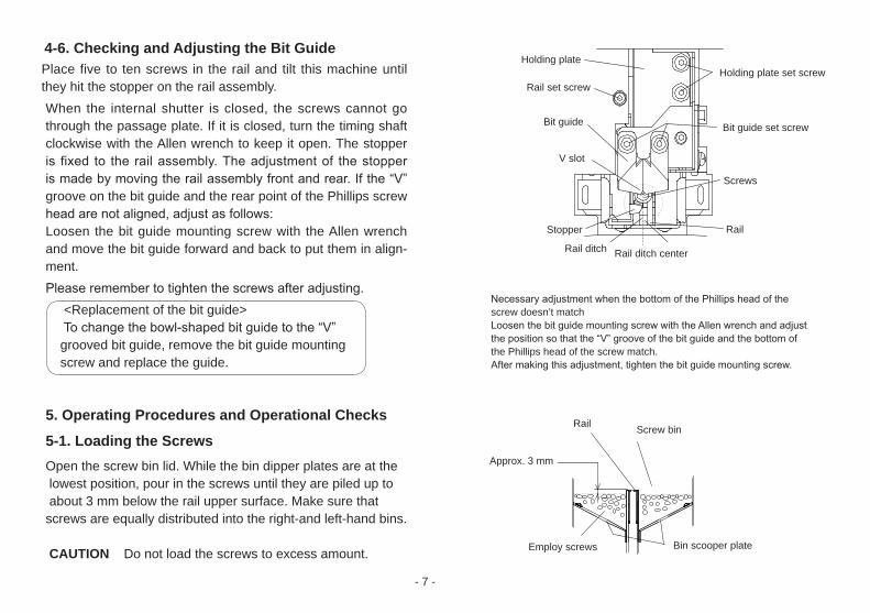
4-6. Checking and Adjusting the Bit GuidePlace five to ten screws in the rail and tilt this machine until they hit the stopper on the rail assembly.When the internal shutter is closed, the screws cannot go through the passage plate. If it is closed, turn the timing shaft clockwise with the Allen wrench to keep it open. The stopper is fixed to the rail assembly. The adjustment of the stopper is made by moving the rail assembly front and rear. If the “V” groove on the bit guide and the rear point of the Phillips screw head are not aligned, adjust as follows:Loosen the bit guide mounting screw with the Allen wrench and move the bit guide forward and back to put them in align-ment.Please remember to tighten the screws after adjusting. <Replacement of the bit guide> To change the bowl-shaped bit guide to the “V” grooved bit guide, remove the bit guide mounting screw and replace the guide.
5. Operating Procedures and Operational Checks
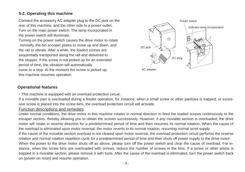
5-1. Loading the ScrewsOpen the screw bin lid. While the bin dipper plates are at the lowest position, pour in the screws until they are piled up to about 3 mm below the rail upper surface. Make sure that screws are equally distributed into the right-and left-hand bins.
CAUTION Do not load the screws to excess amount.
Screws
Holding plate set screw
Bit guide set screw
V slot
Holding plate
Rail set screw
Stopper
Rail ditch Rail ditch center
Bit guide
Rail
Rail
Approx. 3 mm
Bin scooper plate
Screw bin
Employ screws
Necessary adjustment when the bottom of the Phillips head of the screw doesn’t matchLoosen the bit guide mounting screw with the Allen wrench and adjust the position so that the “V” groove of the bit guide and the bottom of the Phillips head of the screw match.After making this adjustment, tighten the bit guide mounting screw.
- 8 -
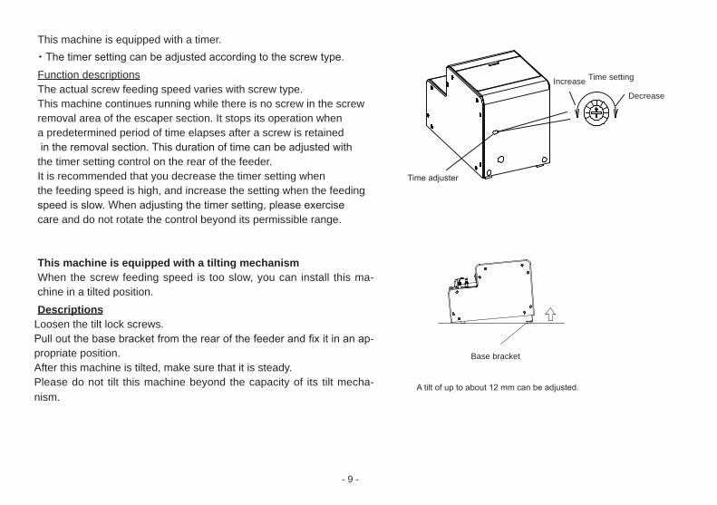
5-2. Operating this machineConnect the accessory AC adapter plug to the DC jack on the rear of this machine, and the other side to a power outlet. Turn on the main power switch. The lamp incorporated in the power switch will illuminate.Turning on the power switch causes the drive motor to rotate normally, the bin scooper plates to move up and down, and the rail to vibrate. After a while, the loaded screws are sequentially transported along the rail and delivered to the stopper. If the screw is not picked up for an extended period of time, the vibration will automatically come to a stop. At the moment the screw is picked up, this machine resumes operation.
Operational features・This machine is equipped with an overload protection circuit.If a movable part is overloaded during a feeder operation, for instance, when a small screw or other particles is trapped, or exces-sive screw is placed into the screw bins, the overload protection circuit will activate.Function descriptions and remediesUnder normal conditions, the drive motor in this machine rotates in normal direction to feed the loaded screws continuously to the escaper section, thereby allowing you to obtain the screws successively. However, if any movable section is overloaded, the drive motor will rotate in reverse direction for a predetermined period of time and then resumes its normal rotation. When the cause of the overload is eliminated upon motor reversal, the motor reverts to its normal rotation, resuming normal scret supply.If the cause of the movable section overload is not cleared upon motor reversal, the overload protection circuit performs the reverse rotation and normal rotation repetition cycle for a predetermined period of time and then shuts off power supply to the drive motor.When the power to the drive motor shuts off as above, please turn off the power switch and clear the cause of overload. For in-stance, when the screw bins are overloaded with screws, reduce the number of screws in the bins. If a screw or other article is trapped in a movable section, please remove it with tools. After the cause of the overload is eliminated, turn the power switch back on (power-on reset) and resume operation.
Power switch
Indicator lamp incorporated
DC plug
AC adapter
DC jack
- 9 -
This machine is equipped with a timer.・The timer setting can be adjusted according to the screw type.Function descriptionsThe actual screw feeding speed varies with screw type.This machine continues running while there is no screw in the screw removal area of the escaper section. It stops its operation when a predetermined period of time elapses after a screw is retained in the removal section. This duration of time can be adjusted with the timer setting control on the rear of the feeder.It is recommended that you decrease the timer setting when the feeding speed is high, and increase the setting when the feedingspeed is slow. When adjusting the timer setting, please exercise care and do not rotate the control beyond its permissible range.
This machine is equipped with a tilting mechanismWhen the screw feeding speed is too slow, you can install this ma-chine in a tilted position.Descriptions
Loosen the tilt lock screws.Pull out the base bracket from the rear of the feeder and fix it in an ap-propriate position.After this machine is tilted, make sure that it is steady.Please do not tilt this machine beyond the capacity of its tilt mecha-nism.
Decrease
Time settingIncrease
Time adjuster
Base bracket
A tilt of up to about 12 mm can be adjusted.
- 10 -
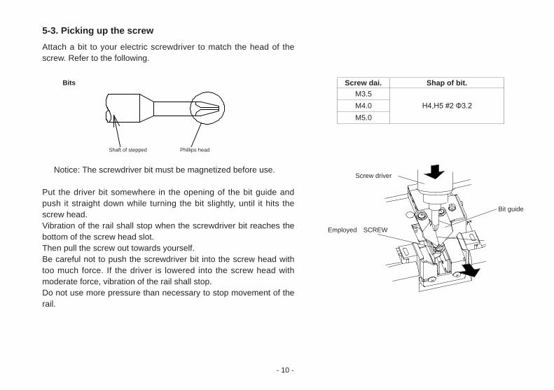
5-3. Picking up the screwAttach a bit to your electric screwdriver to match the head of the screw. Refer to the following.
Notice: The screwdriver bit must be magnetized before use.
Put the driver bit somewhere in the opening of the bit guide and push it straight down while turning the bit slightly, until it hits the screw head.Vibration of the rail shall stop when the screwdriver bit reaches the bottom of the screw head slot.Then pull the screw out towards yourself.Be careful not to push the screwdriver bit into the screw head with too much force. If the driver is lowered into the screw head with moderate force, vibration of the rail shall stop.Do not use more pressure than necessary to stop movement of the rail.
Screw driver
Employed SCREW
Bit guide
①
②
Shaft of stepped
Bits
Phillips head
Screw dai. Shap of bit.M3.5
H4,H5 #2 Φ3.2M4.0M5.0
- 11 -
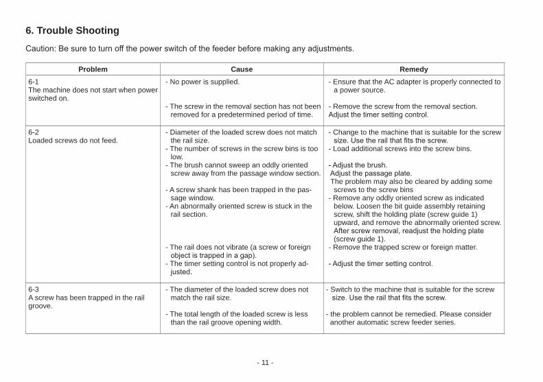
6. Trouble ShootingCaution: Be sure to turn off the power switch of the feeder before making any adjustments.
Problem Cause Remedy6-1The machine does not start when power switched on.
- No power is supplied.
- The screw in the removal section has not been removed for a predetermined period of time.
- Ensure that the AC adapter is properly connected to a power source.
- Remove the screw from the removal section.Adjust the timer setting control.
6-2Loaded screws do not feed.
- Diameter of the loaded screw does not match the rail size.
- The number of screws in the screw bins is too low.
- The brush cannot sweep an oddly oriented screw away from the passage window section.
- A screw shank has been trapped in the pas-sage window.
- An abnormally oriented screw is stuck in the rail section.
- The rail does not vibrate (a screw or foreign object is trapped in a gap).
- The timer setting control is not properly ad-justed.
- Change to the machine that is suitable for the screw size. Use the rail that fits the screw.
- Load additional screws into the screw bins.
- Adjust the brush. Adjust the passage plate. The problem may also be cleared by adding some
screws to the screw bins- Remove any oddly oriented screw as indicated
below. Loosen the bit guide assembly retaining screw, shift the holding plate (screw guide 1) upward, and remove the abnormally oriented screw. After screw removal, readjust the holding plate (screw guide 1).
- Remove the trapped screw or foreign matter.
- Adjust the timer setting control.
6-3A screw has been trapped in the rail groove.
- The diameter of the loaded screw does not match the rail size.
- The total length of the loaded screw is less than the rail groove opening width.
- Switch to the machine that is suitable for the screw size. Use the rail that fits the screw.
- the problem cannot be remedied. Please consider another automatic screw feeder series.
- 12 -
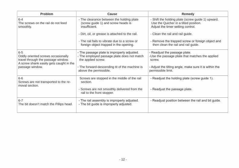
Problem Cause Remedy6-4The screws on the rail do not feed smoothly.
- The clearance between the holding plate (screw guide 1) and screw heads is insufficient.
- Dirt, oil, or grease is attached to the rail.
- The rail fails to vibrate due to a screw or foreign object trapped in the opening.
- Shift the holding plate (screw guide 1) upward. Use the Quicher in a tilted position. Adjust the timer setting control.
- Clean the rail and rail guide.
- Remove the trapped screw or foreign object and then clean the rail and rail guide.
6-5Oddly oriented screws occasionally travel through the passage window.A screw shank easily gets caught in the passage window.
- The passage plate is improperly adjusted.- The employed passage plate does not match the applied screw.
- The forward-descending tit of the machine is above the permissible.
- Readjust the passage plate.-Use the passage plate that matches the applied screw.
- Adjust the tilting angle, make sure it is within the permissible limit.
6-6Screws are not transported to the re-moval section.
Screws are stopped in the middle of the rail section.
- Screws are not smoothly delivered from the rail to the front stopper.
- Readjust the holding plate (screw guide 1).
- Readjust the passage plate.
6-7The bit doesn’t match the Pillips head.
- The rail assembly is improperly adjusted.- The bit guide is improperly adjusted.
- Readjust position between the rail and bit guide.
- 13 -
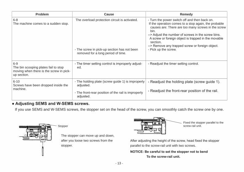
Problem Cause Remedy6-8The machine comes to a sudden stop.
The overload protection circuit is activated.
- The screw in pick-up section has not been removed for a long period of time.
- Turn the power switch off and then back on. If the operation comes to a stop again, the probable
causes are: There are too many screws in the screw bin.
--> Adjust the number of screws in the screw bins. A screw or foreign object is trapped in the movable
section.--> Remove any trapped screw or foreign object.- Pick up the screw.
6-9The bin scooping plates fail to stop moving when there is the screw in pick-up section.
- The timer setting control is improperly adjust-ed.
- Readjust the timer setting control.
6-10Screws have been dropped inside the machine.
- The holding plate (screw guide 1) is improperly adjusted.
- The front-rear position of the rail is improperly adjusted.
- Readjust the holding plate (screw guide 1).
- Readjust the front-rear position of the rail.
● Adjusting SEMS and W-SEMS screws. If you use SEMS and W-SEMS screws, the stopper set on the head of the screw, you can smoothly catch the screw one by one.
Stopper
The stopper can move up and down, after you loose two screws from the stopper.
Fixed the stopper parallel to the screw-rail unit.
After adjusting the height of the screw, head fixed the stopper parallel to the screw-rail unit with two screws.
NOTICE: Be careful to set the stopper not to bend To the screw-rail unit.
- 14 -
Rail guide wall surface (guide surface revealed upon rail assembly removal)
Rail guide
Rail assembly
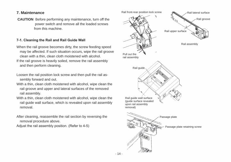
7. Maintenance CAUTION Before performing any maintenance, turn off the power switch and remove all the loaded screws from this machine.
7-1. Cleaning the Rail and Rail Guide Wall
When the rail groove becomes dirty, the screw feeding speed may be affected. If such situation occurs, wipe the rail groove clean with a thin, clean cloth moistened with alcohol.
If the rail groove is heavily soiled, remove the rail assembly and then perform cleaning.
Loosen the rail position lock screw and then pull the rail as-sembly forward and out.
With a thin, clean cloth moistened with alcohol, wipe clean the rail groove and upper and lateral surfaces of the removed rail assembly.
With a thin, clean cloth moistened with alcohol, wipe clean the rail guide wall surface, which is revealed upon rail assembly removal.
After cleaning, reassemble the rail section by reversing the removal procedure above.
Adjust the rail assembly position. (Refer to 4-5)
Rail front-rear position lock screw
Passage plate
Passage plate retaining screw
Rail lateral surface
Rail groove
Rail upper surface
Pull out the rail assembly
- 15 -
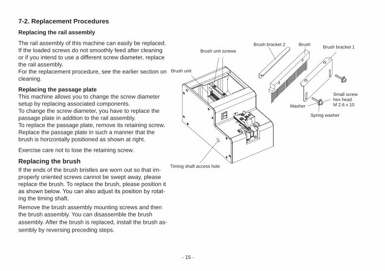
7-2. Replacement ProceduresReplacing the rail assembly
The rail assembly of this machine can easily be replaced.If the loaded screws do not smoothly feed after cleaning or if you intend to use a different screw diameter, replacethe rail assembly.For the replacement procedure, see the earlier section oncleaning.
Replacing the passage plateThis machine allows you to change the screw diametersetup by replacing associated components.To change the screw diameter, you have to replace the passage plate in addition to the rail assembly.To replace the passage plate, remove its retaining screw.Replace the passage plate in such a manner that thebrush is horizontally positioned as shown at right.
Exercise care not to lose the retaining screw.
Replacing the brushIf the ends of the brush bristles are worn out so that im-properly oriented screws cannot be swept away, please replace the brush. To replace the brush, please position it as shown below. You can also adjust its position by rotat-ing the timing shaft.Remove the brush assembly mounting screws and then the brush assembly. You can disassemble the brush assembly. After the brush is replaced, install the brush as-sembly by reversing preceding steps.
Brush unit screws
Brush unit
Brush bracket 1
Timing shaft access hole
Washer
Spring washer
Small screw hex headM 2.6 x 10
Brush bracket 2 Brush
- 16 -
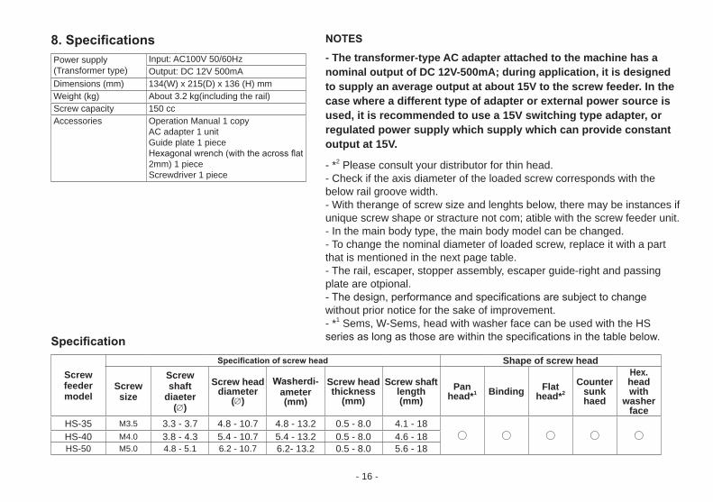
8. Specifications Power supply(Transformer type)
Input: AC100V 50/60HzOutput: DC 12V 500mA
Dimensions (mm) 134(W) x 215(D) x 136 (H) mmWeight (kg) About 3.2 kg(including the rail)Screw capacity 150 ccAccessories Operation Manual 1 copy
AC adapter 1 unitGuide plate 1 pieceHexagonal wrench (with the across flat 2mm) 1 pieceScrewdriver 1 piece
Specification
Screw feeder model
Specification of screw head Shape of screw head
Screw size
Screw shaft
diaeter(∅)
Screw head diameter
(∅)
Washerdi-ameter(mm)
Screw head thickness
(mm)
Screw shaft length (mm)
Pan head*1 Binding Flat
head*2
Countersunkhaed
Hex. head with
washer face
HS-35 M3.5 3.3 - 3.7 4.8 - 10.7 4.8 - 13.2 0.5 - 8.0 4.1 - 18○ ○ ○ ○ ○HS-40 M4.0 3.8 - 4.3 5.4 - 10.7 5.4 - 13.2 0.5 - 8.0 4.6 - 18
HS-50 M5.0 4.8 - 5.1 6.2 - 10.7 6.2- 13.2 0.5 - 8.0 5.6 - 18
NOTES
- The transformer-type AC adapter attached to the machine has a nominal output of DC 12V-500mA; during application, it is designed to supply an average output at about 15V to the screw feeder. In the case where a different type of adapter or external power source is used, it is recommended to use a 15V switching type adapter, or regulated power supply which supply which can provide constant output at 15V.
- *2 Please consult your distributor for thin head.- Check if the axis diameter of the loaded screw corresponds with the below rail groove width.- With therange of screw size and lenghts below, there may be instances if unique screw shape or stracture not com; atible with the screw feeder unit.- In the main body type, the main body model can be changed.- To change the nominal diameter of loaded screw, replace it with a part that is mentioned in the next page table.- The rail, escaper, stopper assembly, escaper guide-right and passing plate are otpional.- The design, performance and specifications are subject to change without prior notice for the sake of improvement.- *1 Sems, W-Sems, head with washer face can be used with the HS series as long as those are within the specifications in the table below.
- 17 -
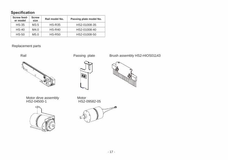
SpecificationScrew feed-
er modelScrew size Rail model No. Passing plate model No.
HS-35 M3.5 HS-R35 HS2-01008-35HS-40 M4.0 HS-R40 HS2-01008-40HS-50 M5.0 HS-R50 HS2-01008-50
Replacement parts
Rail Passing plate Brush assembly HS2-HIOS01143
Motor dirve assembly Motor HS2-04500-1 HS2-09582-05
- 18 -
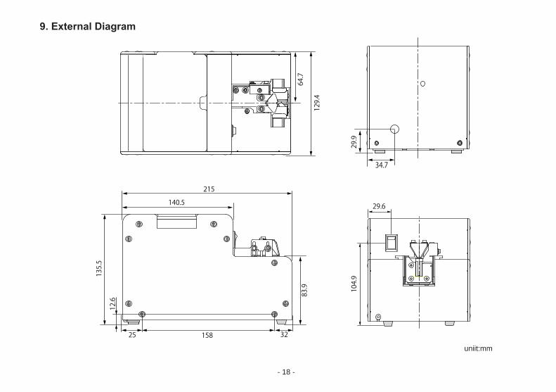
9. External Diagram
29.6
34.7
uniit:mm
- 19 -
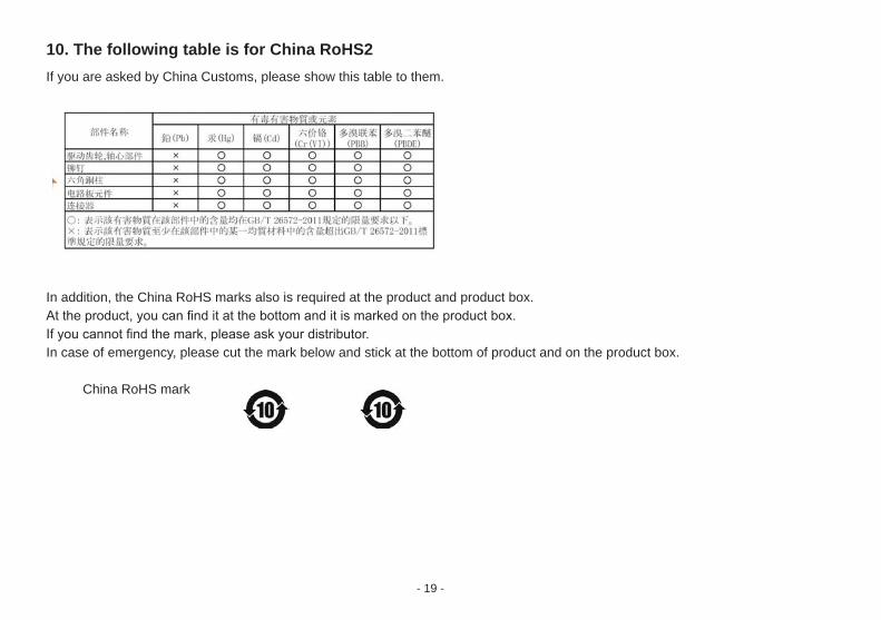
10. The following table is for China RoHS2If you are asked by China Customs, please show this table to them.
In addition, the China RoHS marks also is required at the product and product box.At the product, you can find it at the bottom and it is marked on the product box.If you cannot find the mark, please ask your distributor.In case of emergency, please cut the mark below and stick at the bottom of product and on the product box.
China RoHS mark