Embed Size (px)
Citation preview
TE
CH
NO
LO
GI
CA
L
EX
CE
LL
EN
CE
NEF 280N67 MNT M28
FOR MARINE APPLICATIONS6 CYLINDERS IN LINE - DIESEL CYCLE
206 kW (280 CV) @ 2800 rpm (A1)191 kW (260 CV) @ 2800 rpm (B)147 kW (200 CV) @ 2800 rpm (C)132 kW (180 CV) @ 2500 rpm (D)
N67 MNT M28 FOR MARINE APPLICATIONS
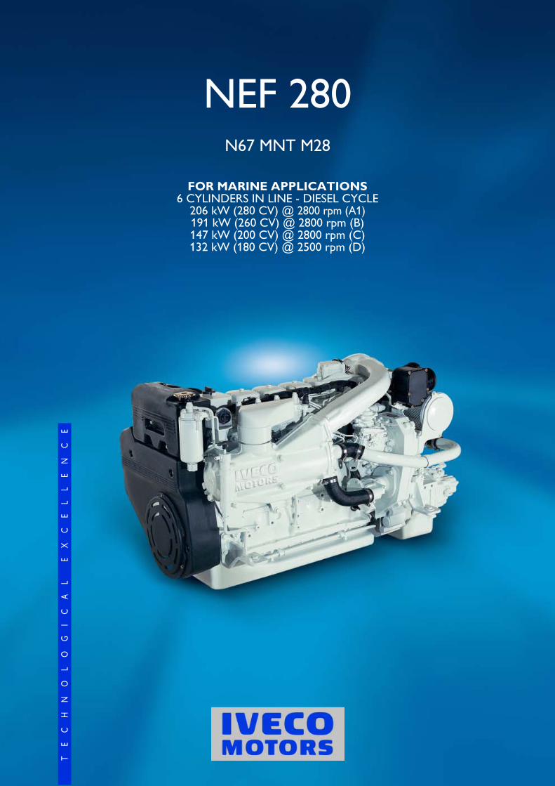
Thermodynamic cycle Diesel 4 stroke - D.I.Air intake TAAArrrangement 6LBore x Stroke mm 104 X 132Total displacement l 6.7Valves per cylinder 2Cooling liquidDirection of rotation (viewed facing flywheel) CCWCompression ratio 17.5 : 1Rotation mass moment of inertia (without flywheel) kgm2 0.32Standard flywheel inertia kgm2 0.71
Air inductionMax suggested intake restriction with clean air filter kPa(bar) 3.5 (0.035)Max allowable restriction with dirty air filter kPa(bar) 6.5 (0.065)Air requirement for combustion at 100% load/rated speed (comb. + ventilation) kg/h (m3/h) 5200 (4500)Turbocharging pressure at full load/rated speed kPa(bar) 150 (1.5)Turbocharging air max temperature (engine inlet) °C 40
Exhaust systemMax allowable backpressure kPa(bar) 10 (0.1)Max exhaust temperature at maximum power °C 580Exhaust flow at max output kg/h 1130
Lubrication systemMinimum oil pressure at idle (at 100°C) kPa(bar) 70 (0.7)Max oil temperature at full load/rated speed °C 120Engine angularity limits continuous operation: max front up and front down 0/360 16 max left hand and right hand 0/360 22 30�Total system capacity including pipes, filters etc. liters 16.5
Sea water cooling system (open circuit)Max intake restriction kPa(bar) 20 (0.2)Sea water pump flow m3/h 12Heat rejected (total) at max power kJ/s(kcal/h) 163.3 (140,000)Sacrifical zinc anodes no 2
Cooling system (closed circuit)Coolant capacity (engine only) liters 24.5Water pump flow at rated speed m3/h 15Thermostat (modulating range) °C 72 ÷ 82Cooling liquid max temperature °C 103Min/max inner pressure in the cooling circuit (for keel cooling) kPa(bar) 10/100 (0.1/1)External cooling system max pressure drop (for keel cooling) kPa(bar) 35 (0.35)
Fuel systemInjection system mechanical pumpGas oil max intake restriction kPa(bar) 15 (0,15)Gas oil max intake temperature °C 40Max fuel backpressure to tank kPa(bar) 30 (0.3)
Electrical systemVoltage V 12
N67 MNT M28 FOR MARINE APPLICATIONS
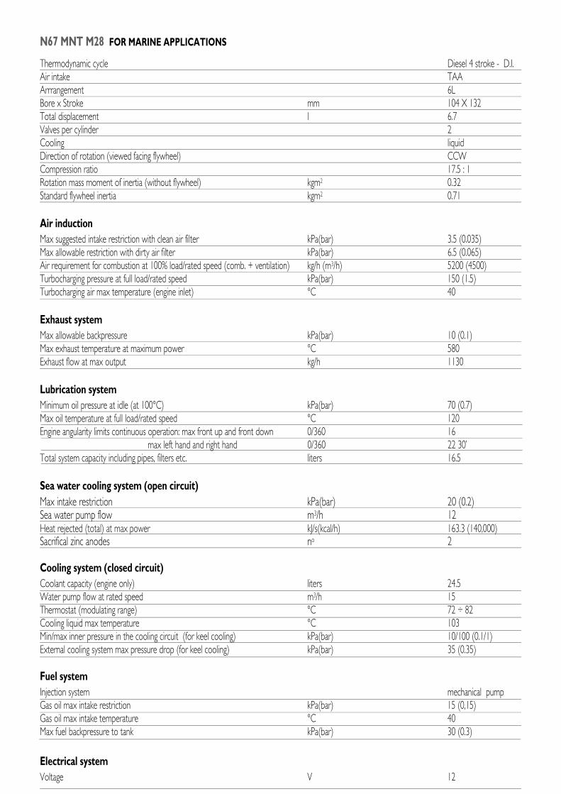
Rating type A1 B C DMaximum power * kW(CV) 206 (280) 191 (260) 147 (200) 132 (180)At speed rpm 2800 2800 2800 2500Maximum no load governed speed at max rating rpm 3150Minimum idling speed rpm 650Mean piston speed at rated speed m/s 12.3 12.3 12.3 11.0BMEP at max torque kg/cm2 18.2 15.2 11.2 11.3Available certifications RINA CCNRSpecific fuel consumption at full load (best value) g/kWh @ rpm 214 @ 2000Oil consumption at max rating (% of fuel consumption) ≤ 0.2Minimum starting temperature without auxiliaries °C - 15Oil and oil filter maintenance interval for replacement hours 600Dry weight (without marine gear) kg 605
* Net Power at flywheel according to ISO 3046/1, after 50 hours running, fuel Diesel EN 590. Power tolerance 5%Test conditions : ISO 3046/1, 25 °C air temperature, 100 kPa atmospheric pressure, 30 % relative humidity.
A1= High performance crafts.B = Light duty.Full throttle operation restricted within10% of total use period.Cruising speed at engine rpm < 90%of rated speed setting - Maximumuseage :- 300 hours per year (A1 service)- 1500 hours per year (B service).
C = Medium duty.Full throttle operation < 25% of useperiod.Cruising speed at engine rpm < 90%of rated speed setting - Maximumuseage 3000 hours per year.
D = Heavy duty.Maximum rating utilisation up to 100%of use period,for unlimited hours peryear.
C DA1 - B
L = 1236 mm
W = 780 mm
H = 793 mm
350
Powe
r - kW
1400
12001000
800
600400To
rque
- Nm
300
280260
240220200
BSFC
- g/k
Wh
rpm
300
250
200
150
100
50
0
1000 1200 1400 1600 1800 2000 2200 2400 2600 2800
rpm1000 1200 1400 1600 1800 2000 2200 2400 2600 2800
rpm1000 1200 1400 1600 1800 2000 2200 2400 2600 2800
350
300
250
200
150
100
50
0
350
300
250
200
150
100
50
0
200
1400
12001000
800
600400
200
1400
12001000
800
600
400
200
300280260
240220200
300
280260
240220
200
A1
B
A1
B
A1
B
N67 MNT M28 FOR MARINE APPLICATIONS
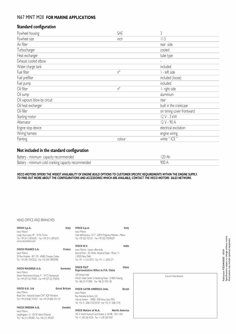
Standard configurationFlywheel housing SAE 3Flywheel size inch 11.5Air filter rear sideTurbocharger cooledHeat exchanger tube typeExhaust cooled elbow -Water charge tank includedFuel filter n° 1 - left sideFuel prefilter included (loose)Fuel pump includedOil filter n° 1- right sideOil sump aluminiumOil vapours blow-by circuit rearOil heat exchanger built in the crankcaseOil filler on timing cover frontwardStarting motor 12 V - 3 kWAlternator 12 V - 90 A Engine stop device electrical excitationWiring harness engine wiringPainting colour white � ICE �
Not included in the standard configurationBattery - minimum capacity recommended 120 AhBattery - minimum cold cranking capacity recommended 900 A
IVECO MOTORS OFFERS THE WIDEST AVAILABILITY OF ENGINE BUILD OPTIONS TO CUSTOMER SPECIFIC REQUIREMENTS WITHIN THE ENGINE SUPPLY.TO FIND OUT MORE ABOUT THE CONFIGURATIONS AND ACCESSORIES WHICH ARE AVAILABLE, CONTACT THE IVECO MOTORS SALES NETWORK.
HEAD OFFICE AND BRANCHES
Local Distributor
Publ
icat
ion
P3D
04N
003E
- 0
9.04
Spec
ifica
tions
sub
ject
to
chan
ge w
ithou
t no
tice
Illus
trat
ions
may
incl
ude
optio
nal e
quip
men
t.IVECO S.p.A. ItalyIveco MotorsLungo Stura Lazio, 49 - 10156 TorinoTel. +39 (011) 0076245 - Fax +39 (011) 0076275www.ivecomotors.com
IVECO FRANCE S.A. FranceIveco Motors50 Rue Ampère - B.P. 103 - 69685 Chassieu Cedex Tel. +33 (04) 72472222 - Fax +33 (04) 78905990
IVECO MAGIRUS A.G. GermanyIveco MotorsHeiner Fleischmann-Strasse, 9 - 74172 NeckarsulmTel. +49 (07132) 97690 - Fax +49 (07132) 976935
IVECO U.K. Ltd Great BritainIveco MotorsRoad One - Industrial Estate CW7 3QP Winsford Tel. +44 (01606) 541027 - Fax +44 (01606) 541124
IVECO SWEDEN A.B. SwedenIveco MotorsLergöksgatan, 12 - 42150 Västra Frölunda Tel. +46 (31) 492450 - Fax +46 (31) 492457
IVECO S.p.A. ItalyIveco MotorsViale dell�Industria, 15/17 - 20010 Pregnana Milanese - MilanoTel. +39 (02) 935101 - Fax +39 (02) 93590029
IVECO N.V. IndiaIveco Motors - Liaison office-IndiaSecond Floor - 50, Okhla Industrial Estate - Phase 111110020 New Delhi Tel. +91 11 51613573 - Fax +91 11 26931271
IVECO FIAT ChinaRepresentative Office in P.R. China
10/F Jinling HotelWorld Trade Center 2 Hanzhong Road - 210005 Nanjing,Tel. +86 25 4710981 - Fax +86 25 4701105
IVECO LATIN AMERICA Ltda. BrazilIveco MotorsRua Alameda da Serra, 222Vale do Sereno - 34000 - 000 Nova Lima (MG)Tel. +55 31 3286 3732/33/34 - Fax +55 31 3286 3735
IVECO Motors of N.A. North America245 E. North Avenue Carol Stream, IL 60188 - 2021 USATel. +1 630 260 4226 - Fax +1 630 260 4267
Rev
isio
nda
te 1
4/01
/05
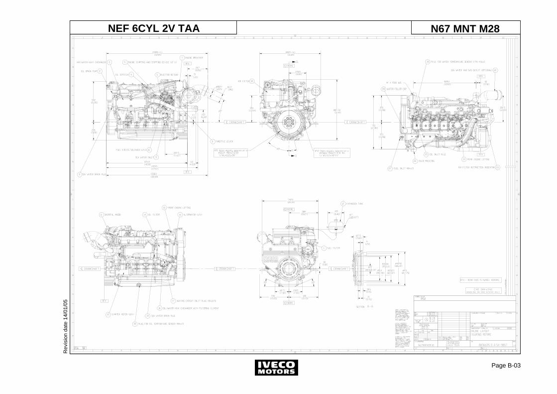
Page B-03
N67 MNT M28NEF 6CYL 2V TAA
Rev
isio
nda
te 1
4/01
/05
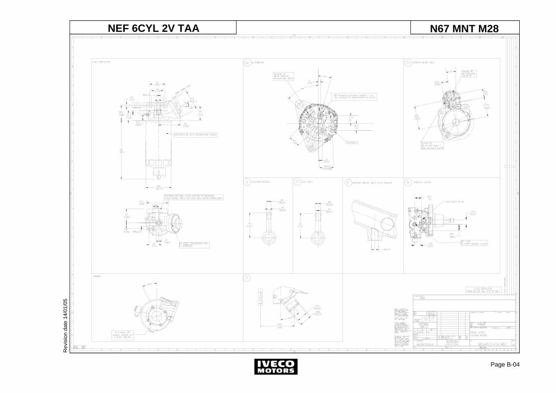
Page B-04
NEF 6CYL 2V TAA N67 MNT M28
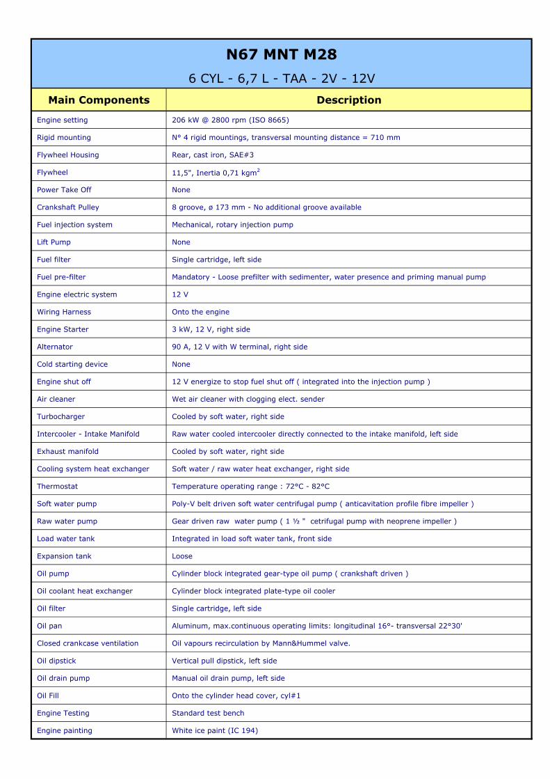
Main Components Description
Engine setting 206 kW @ 2800 rpm (ISO 8665)
Rigid mounting N° 4 rigid mountings, transversal mounting distance = 710 mm
Flywheel Housing Rear, cast iron, SAE#3
Flywheel 11,5", Inertia 0,71 kgm2
Power Take Off None
Crankshaft Pulley 8 groove, ø 173 mm - No additional groove available
Fuel injection system Mechanical, rotary injection pump
Lift Pump None
Fuel filter Single cartridge, left side
Fuel pre-filter Mandatory - Loose prefilter with sedimenter, water presence and priming manual pump
Engine electric system 12 V
Wiring Harness Onto the engine
Engine Starter 3 kW, 12 V, right side
Alternator 90 A, 12 V with W terminal, right side
Cold starting device None
Engine shut off 12 V energize to stop fuel shut off ( integrated into the injection pump )
Air cleaner Wet air cleaner with clogging elect. sender
Turbocharger Cooled by soft water, right side
Intercooler - Intake Manifold Raw water cooled intercooler directly connected to the intake manifold, left side
Exhaust manifold Cooled by soft water, right side
Cooling system heat exchanger Soft water / raw water heat exchanger, right side
Thermostat Temperature operating range : 72°C - 82°C
Soft water pump Poly-V belt driven soft water centrifugal pump ( anticavitation profile fibre impeller )
Raw water pump Gear driven raw water pump ( 1 ½ " cetrifugal pump with neoprene impeller )
Load water tank Integrated in load soft water tank, front side
Expansion tank Loose
Oil pump Cylinder block integrated gear-type oil pump ( crankshaft driven )
Oil coolant heat exchanger Cylinder block integrated plate-type oil cooler
Oil filter Single cartridge, left side
Oil pan Aluminum, max.continuous operating limits: longitudinal 16°- transversal 22°30'
Closed crankcase ventilation Oil vapours recirculation by Mann&Hummel valve.
Oil dipstick Vertical pull dipstick, left side
Oil drain pump Manual oil drain pump, left side
Oil Fill Onto the cylinder head cover, cyl#1
Engine Testing Standard test bench
Engine painting White ice paint (IC 194)
N67 MNT M28
6 CYL - 6,7 L - TAA - 2V - 12V
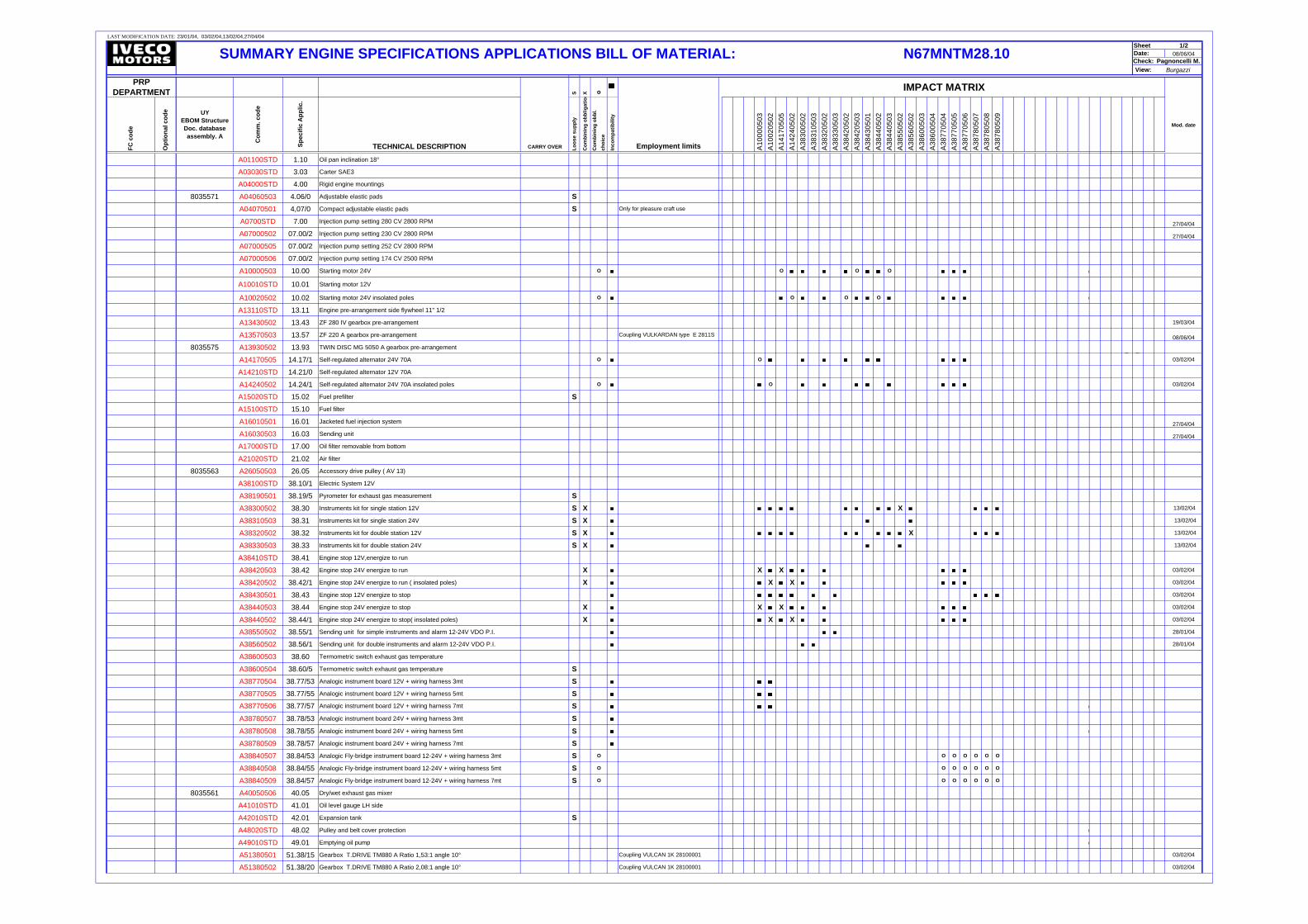
LAST MODIFICATION DATE:
1/208/06/04
Burgazzi
S X o
FC c
ode
Opt
iona
l cod
e UY EBOM Structure Doc. database assembly. A
Com
m. c
ode
Spec
ific
App
lic.
TECHNICAL DESCRIPTION Loos
e su
pply
Com
bini
ng o
bblig
atio
n
Com
bini
ng o
bbl.
ch
oice
Inco
mpa
tibili
ty
A100
0050
3A1
0020
502
A141
7050
5A1
4240
502
A383
0050
2A3
8310
503
A383
2050
2A3
8330
503
A384
2050
2A3
8420
503
A384
3050
1A3
8440
502
A384
4050
3A3
8550
502
A385
6050
2A3
8600
503
A386
0050
4A3
8770
504
A387
7050
5A3
8770
506
A387
8050
7A3
8780
508
A387
8050
9
A01100STD 1.10 Oil pan inclination 18°
A03030STD 3.03 Carter SAE3
A04000STD 4.00 Rigid engine mountings
8035571 A04060503 4.06/0 Adjustable elastic pads SA04070501 4,07/0 Compact adjustable elastic pads S Only for pleasure craft use
A0700STD 7.00 Injection pump setting 280 CV 2800 RPM 27/04/04
A07000502 07.00/2 Injection pump setting 230 CV 2800 RPM 27/04/04
A07000505 07.00/2 Injection pump setting 252 CV 2800 RPM
A07000506 07.00/2 Injection pump setting 174 CV 2500 RPM
A10000503 10.00 Starting motor 24V O O O O
A10010STD 10.01 Starting motor 12V
A10020502 10.02 Starting motor 24V insolated poles O O O O
A13110STD 13.11 Engine pre-arrangement side flywheel 11" 1/2
A13430502 13.43 ZF 280 IV gearbox pre-arrangement 19/03/04
A13570503 13.57 ZF 220 A gearbox pre-arrangement Coupling VULKARDAN type E 2811S 08/06/04
8035575 A13930502 13.93 TWIN DISC MG 5050 A gearbox pre-arrangement
A14170505 14.17/1 Self-regulated alternator 24V 70A O O 03/02/04
A14210STD 14.21/0 Self-regulated alternator 12V 70A
A14240502 14.24/1 Self-regulated alternator 24V 70A insolated poles O O 03/02/04
A15020STD 15.02 Fuel prefilter SA15100STD 15.10 Fuel filter
A16010501 16.01 Jacketed fuel injection system 27/04/04
A16030503 16.03 Sending unit 27/04/04
A17000STD 17.00 Oil filter removable from bottom
A21020STD 21.02 Air filter
8035563 A26050503 26.05 Accessory drive pulley ( AV 13)
A38100STD 38.10/1 Electric System 12V
A38190501 38.19/5 Pyrometer for exhaust gas measurement SA38300502 38.30 Instruments kit for single station 12V S X X 13/02/04
A38310503 38.31 Instruments kit for single station 24V S X 13/02/04
A38320502 38.32 Instruments kit for double station 12V S X X 13/02/04
A38330503 38.33 Instruments kit for double station 24V S X 13/02/04
A38410STD 38.41 Engine stop 12V,energize to run
A38420503 38.42 Engine stop 24V energize to run X X X 03/02/04
A38420502 38.42/1 Engine stop 24V energize to run ( insolated poles) X X X 03/02/04
A38430501 38.43 Engine stop 12V energize to stop 03/02/04
A38440503 38.44 Engine stop 24V energize to stop X X X 03/02/04
A38440502 38.44/1 Engine stop 24V energize to stop( insolated poles) X X X 03/02/04
A38550502 38.55/1 Sending unit for simple instruments and alarm 12-24V VDO P.I. 28/01/04
A38560502 38.56/1 Sending unit for double instruments and alarm 12-24V VDO P.I. 28/01/04
A38600503 38.60 Termometric switch exhaust gas temperature
A38600504 38.60/5 Termometric switch exhaust gas temperature SA38770504 38.77/53 Analogic instrument board 12V + wiring harness 3mt SA38770505 38.77/55 Analogic instrument board 12V + wiring harness 5mt SA38770506 38.77/57 Analogic instrument board 12V + wiring harness 7mt SA38780507 38.78/53 Analogic instrument board 24V + wiring harness 3mt SA38780508 38.78/55 Analogic instrument board 24V + wiring harness 5mt SA38780509 38.78/57 Analogic instrument board 24V + wiring harness 7mt SA38840507 38.84/53 Analogic Fly-bridge instrument board 12-24V + wiring harness 3mt S O O O O O O O
A38840508 38.84/55 Analogic Fly-bridge instrument board 12-24V + wiring harness 5mt S O O O O O O O
A38840509 38.84/57 Analogic Fly-bridge instrument board 12-24V + wiring harness 7mt S O O O O O O O
8035561 A40050506 40.05 Dry/wet exhaust gas mixer
A41010STD 41.01 Oil level gauge LH side
A42010STD 42.01 Expansion tank SA48020STD 48.02 Pulley and belt cover protection
A49010STD 49.01 Emptying oil pump
A51380501 51.38/15 Gearbox T.DRIVE TM880 A Ratio 1,53:1 angle 10° Coupling VULCAN 1K 28100001 03/02/04
A51380502 51.38/20 Gearbox T.DRIVE TM880 A Ratio 2,08:1 angle 10° Coupling VULCAN 1K 28100001 03/02/04
N67MNTM28.10Sheet
23/01/04, 03/02/04,13/02/04,27/04/04
Employment limits
Mod. date
Date: Check: Pagnoncelli M.View:
IMPACT MATRIXPRP DEPARTMENT
SUMMARY ENGINE SPECIFICATIONS APPLICATIONS BILL OF MATERIAL:
CARRY OVER
a
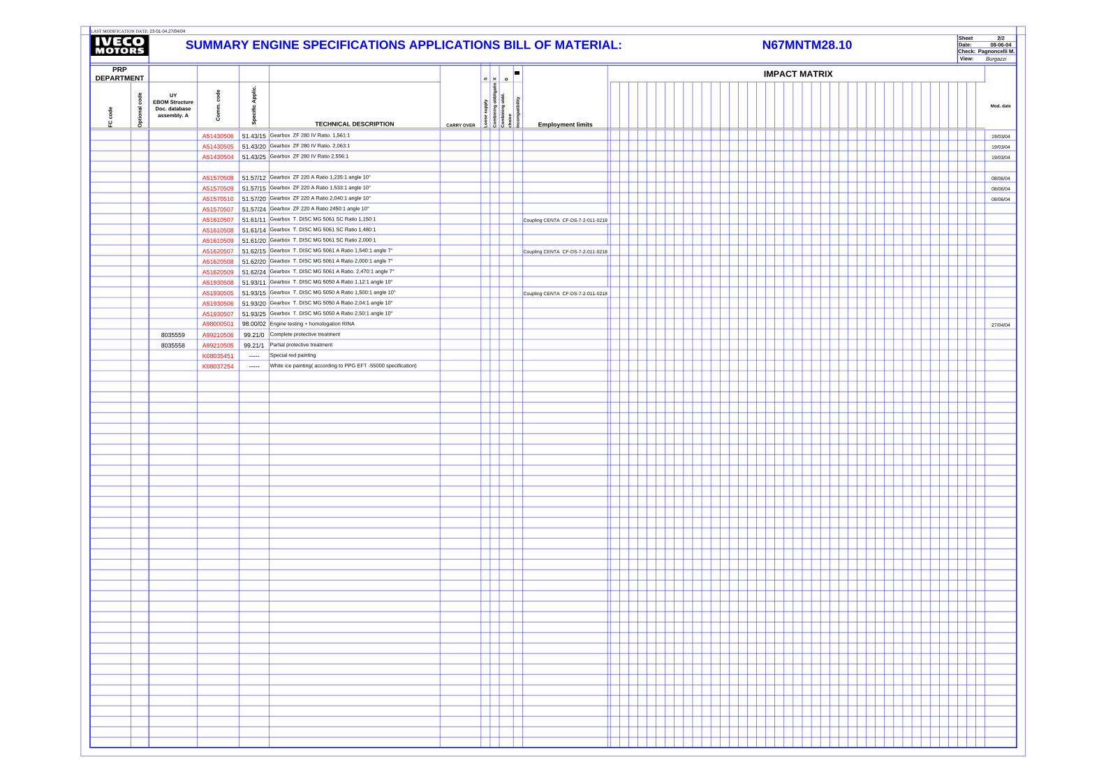
LAST MODIFICATION DATE:
2/208-06-04
Burgazzi
S X o
FC c
ode
Opt
iona
l cod
e UY EBOM Structure Doc. database assembly. A
Com
m. c
ode
Spec
ific
App
lic.
TECHNICAL DESCRIPTION Loos
e su
pply
Com
bini
ng o
bblig
atio
n
Com
bini
ng o
bbl.
ch
oice
Inco
mpa
tibili
ty
A51430506 51.43/15 Gearbox ZF 280 IV Ratio. 1,561:1 19/03/04
A51430505 51.43/20 Gearbox ZF 280 IV Ratio. 2,063:1 19/03/04
A51430504 51.43/25 Gearbox ZF 280 IV Ratio 2,556:1 19/03/04
A51570508 51.57/12 Gearbox ZF 220 A Ratio 1,235:1 angle 10° 08/06/04
A51570509 51.57/15 Gearbox ZF 220 A Ratio 1,533:1 angle 10° 08/06/04
A51570510 51.57/20 Gearbox ZF 220 A Ratio 2,040:1 angle 10° 08/06/04
A51570507 51.57/24 Gearbox ZF 220 A Ratio 2450:1 angle 10°
A51610507 51.61/11 Gearbox T. DISC MG 5061 SC Ratio 1,150:1 Coupling CENTA CF-DS-7-2-011-0218
A51610508 51.61/14 Gearbox T. DISC MG 5061 SC Ratio 1,480:1
A51610509 51.61/20 Gearbox T. DISC MG 5061 SC Ratio 2,000:1
A51620507 51.62/15 Gearbox T. DISC MG 5061 A Ratio 1,540:1 angle 7° Coupling CENTA CF-DS-7-2-011-0218
A51620508 51.62/20 Gearbox T. DISC MG 5061 A Ratio 2,000:1 angle 7°
A51620509 51.62/24 Gearbox T. DISC MG 5061 A Ratio. 2,470:1 angle 7°
A51930508 51.93/11 Gearbox T. DISC MG 5050 A Ratio 1,12:1 angle 10°
A51930505 51.93/15 Gearbox T. DISC MG 5050 A Ratio 1,500:1 angle 10° Coupling CENTA CF-DS-7-2-011-0218
A51930506 51.93/20 Gearbox T. DISC MG 5050 A Ratio 2,04:1 angle 10°
A51930507 51.93/25 Gearbox T. DISC MG 5050 A Ratio 2,50:1 angle 10°
A98000501 98.00/02 Engine testing + homologation RINA 27/04/04
8035559 A99210506 99.21/0 Complete protective treatment
8035558 A99210505 99.21/1 Partial protective treatment
K08035451 ----- Special red painting
K08037254 ----- White ice painting( according to PPG EFT -55000 specification)
Mod. date
Date: Check:
Sheet 23-01-04,27/04/04
SUMMARY ENGINE SPECIFICATIONS APPLICATIONS BILL OF MATERIAL: N67MNTM28.10Pagnoncelli M.
View:
Employment limits
IMPACT MATRIXPRP DEPARTMENT
CARRY OVER