Embed Size (px)
Citation preview
Need, Potential and Might of Geotechnical Instrumentation in India*
by
H. C. Verma**
INTRODUCTION
An instrument according to Webster, the great lexicographer, can have widely different meanings dependent on the context in which it is used. It can mean an agency, agent or medium such as 'a police force is an instrument for keeping law and order'. It becomes a legal document, contract, deed, character·, paper or grant when we say the Lawyers will draw up all the necessary instruments. I would like to use this word to mean an implement, a tool, an appliance, a contrivance, a mechanism, a gadget or a device for precise measurement. Instrumentation, likewise should mean the science and art concerned with the R & D, manufacture and usage of instruments.
Instrumentation has permeated into every sphere of our activity. Our interaction with it commences with the very act of our creation. Everything we do involves an 'Instrument.' Those who are familiar with the game of cricket would have seen a cricket captain, even today, use his 'thumb' or 'toe' or both to test the nature of the turf. His assessment leads to his crucial decision to 'bat' or 'field' his team.lf he happens to be a geotechnical engineer, he may whip out a pocket penetrometer and use it (albeit with the umpire's back turned) to obtain more reliable information. The blacksmith of old, judges his steel by its ring; the present-day engineer prefers a Brinell or Rockwell number. The textile worker, by his feel, assesses the humidity. Today he would need a moisture meter.
In this lecture, I intend to introduce the origin of instrumentation industry in India and the backing it received from the Government. Later on, I will deal in some detail the rise, need, potential and might of geotechnical instrumentation. Towards the end of my lecture, I will cover the necessity for standardisation, maintenance management and research and development in this important area.
Simple instruments for teaching science got a start off in India at the turn of the Century with Master Hargolal, a science teacher who later set up a company known as 'Hargolal and Sons' in Ambala. This organisation became the training ground for all manufacturers of instruments and apparatuses for teaching science. We have now several manufacturing units in India ranging from single ownership on one hand to those employing a few hundred on the other.
The Surveying instrument Industry was the first to develop. It began in and around Roorkee and got a tremendous impetus due to the Thomason College of Engineering, now the University of Roorkee. Old craftsmen are now manufacturers of a range of instruments they once repaired. It took several representations and many years before instrument industry was given recognition by the Government of India. Despite Thacker Committee and Kothari Committee recommendations, instruments continued to be clubbed with commodities like bicycles and sewing machines. A Development Council for Instruments was eventually constituted by the Ministry of Industry to examine the status, assess the requirements and recommend measures for !he planned growth of this Industry. The Bhabha Committee Report of 1966 constituted a milestone for the development of Electronics Industry. Subsequently, the Electronics Commission was set up by the Government of India in 1973.
The first organised steps to set up manufacture of a range of instruments in the field of materials testing was taken in 1956 when Associated Instrument Manufacturers (India) Private Limited (AIMIL) secured an industrial licence from the Ministry of Industry. A range of instruments were produced for testing of building materials such as cement, aggregate, concrete. AI MIL were among the first to produce a complete range of Civil engineering equipment and instruments. With the wealth of expertise and experience accumulated over a period of years, the switch over to the production of geotechnical instruments was rather smooth. Encouragement of eminent Indian geotechnical engineers in universities, technical institutions, national laboratories etc. hastened the pace of development giving a big boost to the range and quality of production.
With time, ancilliarisation came to be the order of the day and several units are now manufacturing a fairly comprehensive range of insturments to cater to the needs of routine soil mechanics instrumentation for laboratory
*Fifth IGS Annual Lecture delivered on the occasion of its 24th Annual General Session held at the Conference Room, Bombay Market, Surat on December 20, 1982. -Chairman and Managing Director, Associated Instrument Manufacturers (India) Pvt. Ltd., New Delhi.
157
and field investigations.
Some units have started entering the field of Instrumentation for Rock Mechanics. The advent of electronics has given a fillip to development of instruments and equipment by interfacing transducers as measuring devices and using digital techniques for display and recording.
NEED FOR GEOTECHNICAL INSTRUMENTATION
Prior to the first quarter of the 20th century, the growth ot Soil Mechanics was rather slow and largely empirical although flashes of brilliant experimental work were occasionally seen. Then came the grand era of classical Soil Mechanics firmly founded on Terzaghi's extraordinary contributions, particularly the discovery of the principle of effective stress. Today, Soil Mechanics is greatly enriched by Geology, Rock Mechanics, Snow Mechanics, Mathematics, Physics, Chemistry, Mineralogy, Electronics, Computronics and a host of other disciplines of knowledge, so much so that the subject once thought of as highly specialised by itself has now fragmented into several distinctly well defined sub disciplines.
Soil is an extremely complex material whose behaviour is influenced by a multitude of factors including its own history of formation and time effects. Despite the phenomenal progress on all facets and fronts, truely scientific analyses of geotechnical problems remain a far cry and perhaps a well nigh impossible proposition. This is the reason that there falls the proverbial shadow between prediction and performance and naturally the designs are either conservative or sometimes unsafe. Every conservative design means many crores of Rupees of extra expenditure on national scale and every failure means loss of opportunity, of time, of money and even life. The failures are however best of the school masters, if properly studied, understood and taken advantage of. The real progress therefore lies in more and more of performance studies, field observations and consequent rejection or refinement of theories. 'In soil mechanics, the accuracy of computed results never exceeds that of a crude estimate and the principal function of theory consists in teaching us what and how to observe in the field', Terzaghi (1936).
Viewed in this context, the need for an elaborate carefully planned and conscentiously executed programme of geotechnical instrumentation can never be overemphasized atleast in so far as major geotechnical engineering projects of stringent requirement and doubtful performance are concerned.
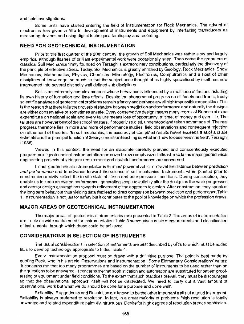
In fact, geotechnical instrumentation is the most powerful vehicle to travel the distance between prediction and performance and to advance forward the science of soli mechanics. Instruments when planted prior to construction activity reflect the in-situ state of stress and pore pressure conditions. During construction, they enable us to keep an eye on performance, generating scope to suitably alter the design as the work progresses and censor design assumptions towards refinement of the approach to design. After construction, they speak of the long term behaviour thus yielding data that lead to direct comparison between prediction and performance, Table 1. Instrumentation is not just for safety but it contributes to the pool of knowledge on which the profession draws.
MAJOR AREAS OF GEOTECHNICAL INSTRUMENTATION
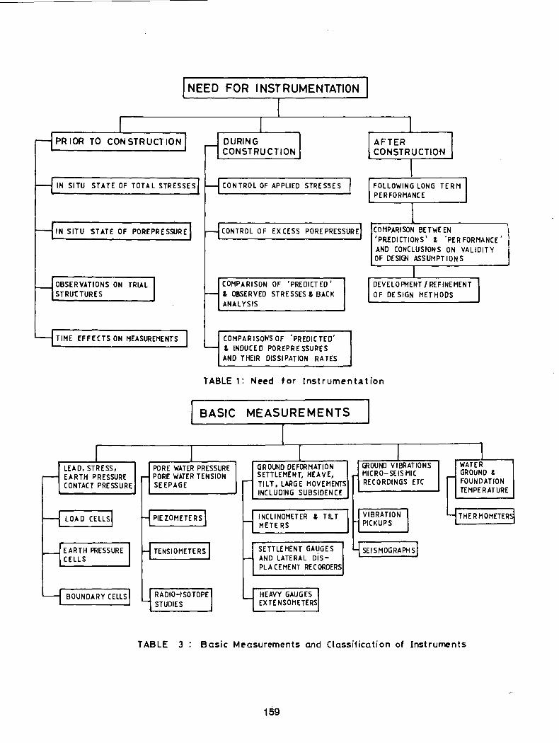
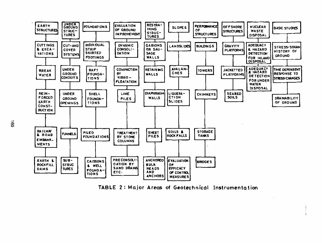
The major areas of geotechnical intrumentation are presented in Table 2.The areas of instrumentation are truely as wide as the need for instrumentation.Table 3 summarises basic measurements and classification of instruments through which these could be achieved.
CONSIDERATIONS IN SELECTION OF INSTRUMENTS
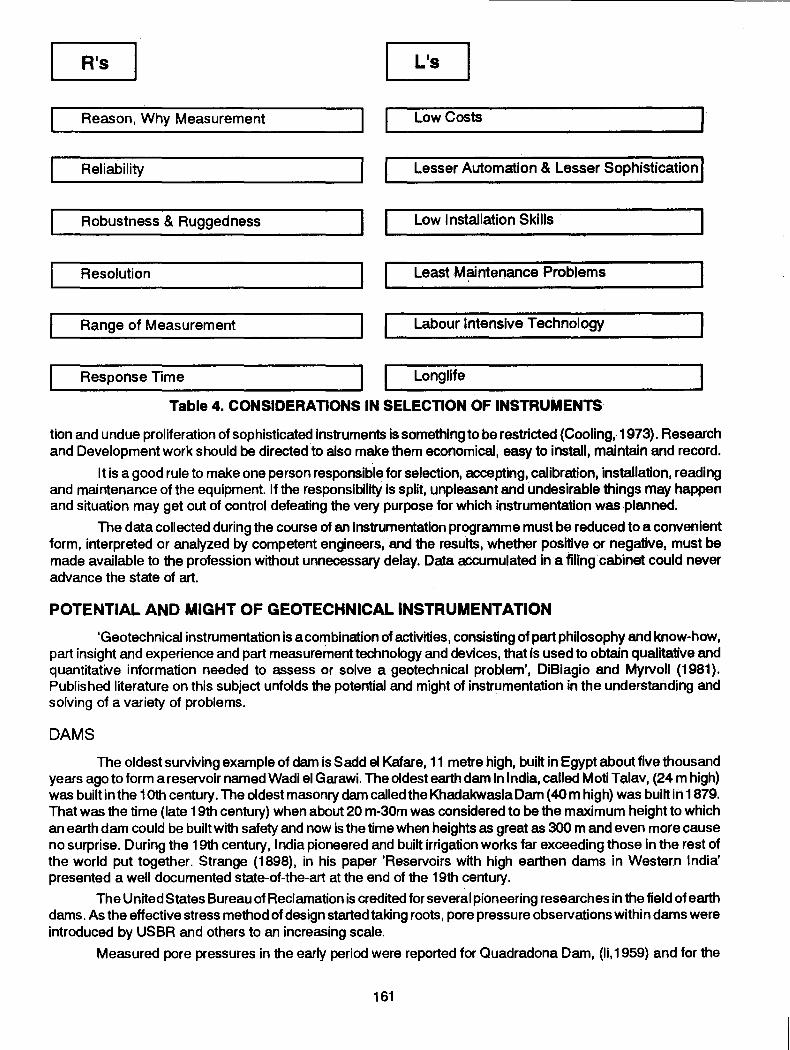
The usual considerations in selection of instruments are best described by 6R's to which must be added 6L's to develop technology appropriate to India, Table 4.
Evey instrumentation proposal must be drawn with a definitive purpose. The point is best made by quoting Peck, who in his article 'Observations and Instrumentation: Some Elementary Considerations' writes: 'It concerns me that too many programmes are based on the number of instruments to be used rather than on the questions to be answered. It concerns me that sophistication and automation are substituted for patient prooftesting of equipment under field conditions. To the extent that such practices prevail, they must be discouraged so that the observational approach itself will not be discredited. We need to carry out a vast amount of observational work but what we do should be done for a purpose and done well'.
Reliability, Ruggedness and Resolution are known to be the other important traits of a good instrument. Reliability is always preferred to resolution. In fact, in a great majority of problems, nigh resolution is totally unwanted and related expenditure painfully infructuous. Desire for high degrees of resolution breeds sophistica-
158
I NEED FOR INSTRUMENTATION
I I I I
rl PR lOR TO CONSTRUCT ION I r-1 DURING CONSTRUCTION
AFTER I CONSTRUCTION
I H IN SITU STATE OF TOTAL STRESsEs! H CONTROL OF APPLIED STRESSES FOLLOWING LONG TERM]
PERFORMANCE
\ H IN SITU STATE OF POREPRESSURE 1 HcoNTROL oF ExcEss POREPRESSUREj COMPARISON BET WE EN l
'PREDICTIONS' I. .PERFORMANCE' l AND CONCLUSIONS ON VALID! T Y J OF DESI~ ASSUMPTIONS
I H OBSERVATIONS ON TRIAL I COMPARISON OF 'PREDICTED' DEVELOPMENT I REFINEMENT ] STRUtTURES ~ & OBSERVED STRESSES & BACK OF DESIGN METHODS
ANALYSIS
TIME EFFECTS ON MEASUREMENTS I COMPARISONS OF 'PREDICTED' - & ~DUCED POREPRESSUPES AND THEIR DISSIPATION RATES
TABLE 1: Need for Instrumentation
I BASIC MEASUREMENTS I I
I I I I I LEAD, STRESS, PORE WATER PRESSURE GROUND DEFORMATION GROUND VIBRATIONS WATER
r-- EARTH PRESSURE r- PORE WATER TENSION SETTLEMENT, HEAVE, MICRO-SEISMIC ,.... GROUND &
CONTACT PRESSURE SEEPAGE .-- TILT, LARGE MOVEMENTS RECORDINGS ETC FOUNDATION
INCLUDING SUBSIDENCf TEMPERATURE
H LOAD CELLsJ H PIEZOMETERsl H INC Ll NOMETER , TILT METERS I ~VIBRATION ' PICKUPS
THERMOMETE~
HEARTH PRESSURE I H TENSIOMETERS 1 SETTLEMENT GAUGES 4 SEISMOGRAPHsl CELLS ~ AND LATERAL DIS-
PLACEMENT RECORDERS
~ BOUNDARY CELLS I y RADIO-ISOTOPE I STUDIES
HEAVY GAUGES sl EXTE NSOMETERS
TABLE 3 Basic Measurements and Classification of Instruments
159
EARTH STRUCTURES
CUTTINGS & EXCA-'tAT IONS
BREAK WATER
REIN-FORCED EARTH CONST-RUCTION
...... ~
RAILWN & ROAD
EMBANK-MENTS
EARTH & ROCK FILL DAMS
' -
UNDER GROUND STRUCTURES
CUT-AND COVER SYSTEMS
UNDER GROUND
CONDUITS
UNDER
GROUND OPENINGS
SUBSTRUC TURES
INDIVIDUAL STRIP SKIRTED FOOTINGS
RAFT FOUNDATIONS
SHELL
FOUNDATIONS
PILED FOUND AT IONS
CAISSONS & WELL FOUNDATIONS
I
I
.
EVALUATION l OF GROUND I
IMPROVEMENT]
I DYNAMIC
CONSOLI-DATION
COMPACTION BY VIBRO-
FLOATATION
I LIME
PILES
TREATMENT BY STONE COLUMNS
PRE CONSOli-DATION BY SAND DRAINS ETC.
- --
RESTRA-IN lNG STRUC-TURES
_L
GABIONS OR SAU-SAGE WALLS
RETAIIUIG WALLS
DIAPHRAGM WALLS
SHEET PILES
ANCHORED BULK HEADS AND ANCHORS
SLOPES
LANDSLIDES
AVA LAN-CHES
LIOUEFA-CTION SLIDES
SOILS t ROCKFALLS
EVALUATION OF EFFICACY OF CONTROL MEASURES
STORAGE TAt«S
OFFSHORE NUCLEAR STRUCfURES WASTE
DISPOSAL
j_
GRAYITY ADEQUACY
PLATFORMS & HAZARD DETECTION FOR INLAND DISPOSAL
JACKETT ED ADEQUACY
PLATFORMS &. HAZARD DETECTION
I FOR UNDER WATER DISPOSAL
SEABED SOILS
TABLE 2: Major Areas of Geotechnical Instrumentation
BASIC STUDIES
STRES5-STRAIN HISTORY OF GROUND
TIME DEPENDENT RESPONSE TO STIESS-CHANGES
DRAINABILITY OF GROUND ........_
R•s L•s
Reason, Why Measurement Low Costs
Reliability Lesser Automation & Lesser Sophistication f
Robustness & Ruggedness Low Installation Skills
Resolution Least Maintenance Problems
Range of Measurement Labour Jntensive Technology
Response Time Long life
Table 4. CONSIDERATIONS IN SELECTION OF INSTRUMENTS
tion and undue proliferation of sophisticated instruments is something to be restricted (Cooling,.1973). Research and Development work should be directed to also make them economical, easy to install, maintain and record.
It is a good rule to make one person responsible for selection, accepting, calibration, installation, reading and maintenance of the equipment. If the responsibility is split, unpleasant and undesirable things may happen and situation may get out of control defeating the very purpose for which instrumentation was .planned.
The data collected during the course of an instrumentation programme must be reduced to a convenient form, interpreted or analyzed by competent engineers, and the results, whether positive or negative, must be made available to the profession without unnecessary delay. Data accumulated in a filing cabinet could never advance the state of art. ·
POTENTIAL AND MIGHT OF GEOTECHNICAL INSTRUMENTATION
'Geotechnical instrumentation is a combination of activities, consisting of part philosophy and know-how, part insight and experience and part measurement technology and devices, that is used to obtain qualitative and quantitative information needed to assess or solve a geotechnical problem', DiBiagio and Myrvoll (1981). Published literature on this subject unfolds the potential and might of instrumentation in the understanding and solving of a variety of problems.
DAMS
The oldest surviving example of dam is Sadd el Kafare, 11 metre high, built in Egypt about five thousand years ago to form a reservoir named Wadi el Garawi. The oldest earth dam in India, called Moti Tf;llav, (24m high) was built in the 1Oth century. The oldest masonry dam called the Khadakwasla Dam ( 40 m high) was built iii 1879. That was the time (late 19th century) when about 20 m-30m was considered to be the maximum height to which an earth dam could be built with safety and now is the time when heights as great as 300 m and even more cause no surprise. During the 19th century, India pioneered and built irrigation works far exceeding those in the rest of the world put together. Strange (1898), in his paper 'Reservoirs with high earthen dams in Wester.n India' presented a well documented state-of-the-art at the end of the 19th century.
The United States Bureau of Reclamation is credited for several pioneering researches in the field of earth dams. As the effective stress method of design started taking roots, pore pressure observations within dams were introduced by USBR and others to an increasing scale.
Measured pore pressures in the early period were reported for Ouadradona Dam, (li, 1959) and for the
161
"' 11.1 « .... 11.1 %
% <C Q
II. 0
... ::r ~
1&.1 ::r
320
210
240
1 KISHAU DAM
2 TEHRI DAM
3 RAMGANGA DAM
-- -____ ....,.. __ ,...._.. ...,.
I I ~,
~2 I
' al I I I
I I
f3 ,. ,. ,~'~
OL---------~-----L--~~~--~~~~~ 1910 20 30 '0 60 70 80 90
YEAR
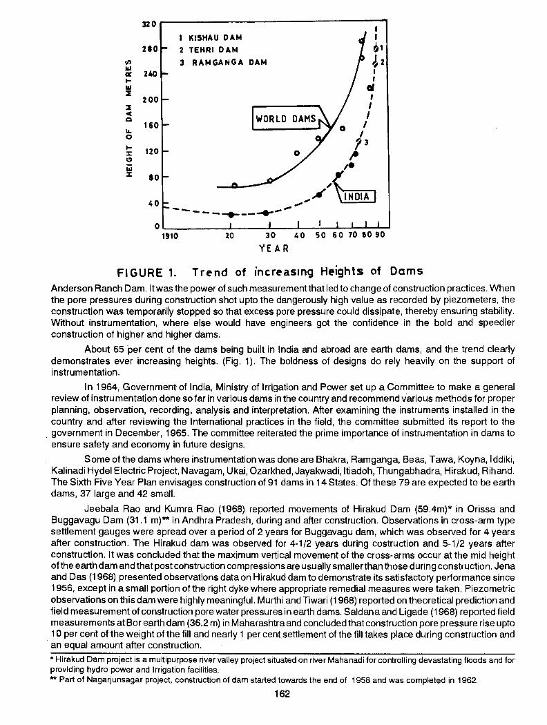
FIGURE 1. Trend of increasmg Heights of Dams Anderson Ranch Dam. I twas the power of such measurement that led to change of construction practices. When the pore pressures during construction shot upto the dangerously high value as recorded by piezometers, the construction was temporarily stopped so that excess pore pressure could dissipate, thereby ensuring stability. Without instrumentation, where else would have engineers got the confidence in the bold and speedier construction of higher and higher dams.
About 65 'per cent of the dams being built in India and abroad are earth dams, and the trend clearly demonstrates ever increasing heights. (Fig. 1). The boldness of designs do rely heavily on the support of instrumentation.
In 1964, Government of India, Ministry of Irrigation and Power set up a Committe8 to make a general review of instrumentation done so far in various dams in the country and recommend various methods for proper planning, observation, recording, analysis and interpretation. After examining the instruments installed in the country and after reviewing the International practices in the field, the committee submitted its report to the government in December, 1965. The committee reiterated the prime importance of instrumentation in dams to ensure safety and economy in future designs.
Some of the dams where instrumentation was done are Bhakra, Ramganga, Beas, Tawa, Koyna, lddiki, Kalinadi Hydel Electric Project, Navagam, Ukai, Ozarkhed, Jayakwadi, ltiadoh, Thungabhadra, Hirakud, Rihand. The Sixth Five Year Plan envisages construction of 91 dams in 14 States. Of these 79 are expected to be earth dams, 37 large and 42 small.
Jeebala Rao and Kumra Rao (1968) reported movements of Hirakud Dam (59.4m)* in Orissa and Buggavagu Dam (31 .1 m)** in Andhra Pradesh, during and after construction. Observations in cross-arm type settlement gauges were spread over a period of 2 years for Buggavagu dam, which was observed for 4 years after construction. The Hirakud dam was observed for 4-1/2 years during costruction and 5-1/2 years after construction. It was concluded that the maximum vertical movement of the cross-arms occur at the mid height of the earth dam and that post construction compressions are usually smaller than those during construction. Jena and Das (1968) presented observations data on Hirakud dam to demonstrate its satisfactory performance since 1956, except in a small portion of the right dyke where appropriate remedial measures were taken. Piezometric observations on this dam were highly meaningful. Murthi and Tiwari (1968) reported on theoretical prediction and field measurement of construction pore water pressures in earth dams. Saldana and Ligade (1968) reported field measurements at Bor earth dam (36.2 m) in Maharashtra and concluded that construction pore pressure rise upto 1 0 per cent of the weight of the fill and nearly 1 per cent settlement of the fill takes place during construction and
· an equal amount after construction.
* Hirakud Dam project is a multipurpose river valley project situated on river Mahanadi for controlling devastating floods and for providing hydro power and Irrigation facilities. ** Part of Nagarjunsagar project, construction of dam started towards the end of 1958 and was completed in 1962.
162
Datye (1968), while presenting experiences on some earth dams in Maharashtra, reinforced the concept of detailing earth dams to minimise cracking hazards. The cracks could develop at the junctions of the embankments with masonry dams, hil.l flanks at the abuntments or at locations where foundation profiles are extremely irregular such as crossing of outlet and cut-off trenches. Instrumentation is required for monitoring strains within the body of the dam particularly at vulnerable points, from which potentiality of cracking could be deduced and remedial measures undertaken.
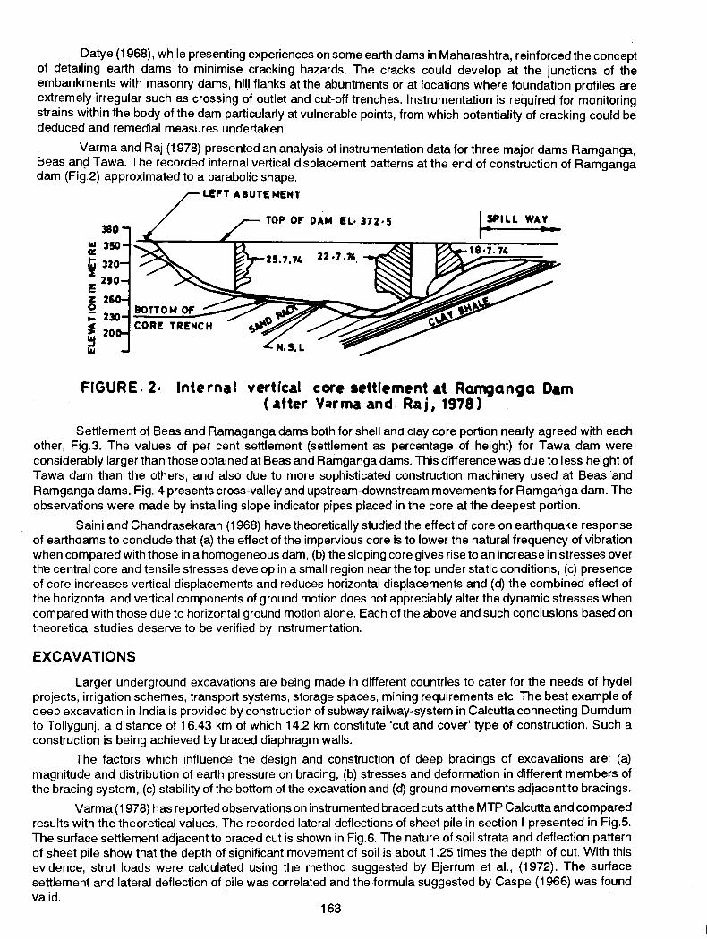
Varma and Raj (1978) presented an analysis of instrumentation data for three major dams Ramganga, E::seas an9 Tawa. The recorded internal vertical displacement patterns at the end of construction of Ramganga dam (Fig.2) approximated to a parabolic shape.
z 2 ... • 20 ~ IU
LEFT AI UTE MENT
TOP OF DAM EL• 372•5
FIGURE. 2· Internal vertical core settlement ~t RCII'n'1Janga D~m (after Varma and Raj, 1978)
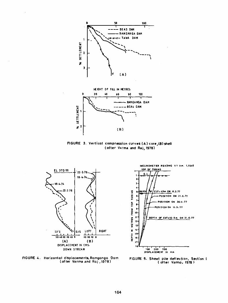
Settlement of Seas and Ramaganga dams both for shell ano clay core portion nearly agreed with each other, Fig.3. The values of per cent settlement (settlement as percentage of height) for Tawa dam were considerably larger than those obtained at Seas and Ramganga dams. This difference was due to less height of Tawa dam than the others, and also due to more sophisticated construction machinery used at Seas ·and Ramganga dams. Fig. 4 presents cross-valley and upstream-downstream movements for Ramgariga dam. The observations were made by installing slope indicator pipes placed in the core at the deepest portion.
Saini and Chandrasekaran (1968) have theoretically studied the effect of core on earthquake response of earthdams to conclude that (a) the effect of the impervious core is to lower the natural frequency of vibration when compared with those in a homogeneous dam, (b) the sloping core gives rise to an increase in stresses over the central core and tensile stresses develop in a small region near the top under static conditions, (c) presence of core increases vertical displacements and reduces horizontal displacements and (d) the combined effect of the horizontal and vertical components of ground motion does not appreciably after the dynamic stresses when compared with those due to horizontal ground motion alone. Each of the above and such conclusions based on theoretical studies deserve to be verified by instrumentation.
EXCAVATIONS
Larger underground excavations are being made in different countries to cater for the needs of hydel projects, irrigation schemes, transport systems, storage spaces, mining requirements etc. The best example of deep excavation in India is provided by construction of subway railway-system in Calcutta connecting Dumdum to Tollygunj, a distance of 16.43 km of which 14.2 km constitute 'cut and cover' type of construction. Such a construction is being achieved by braced diaphragm walls.
The factors which influence the design and construction of deep bracings of excavations are: (a) magnitude and distribution of earth pressure on bracing, (b) stresses and deformation in different members of the bracing system, (c) stability of the bottom of the excavation and (d) ground movements adjacent to bracings.
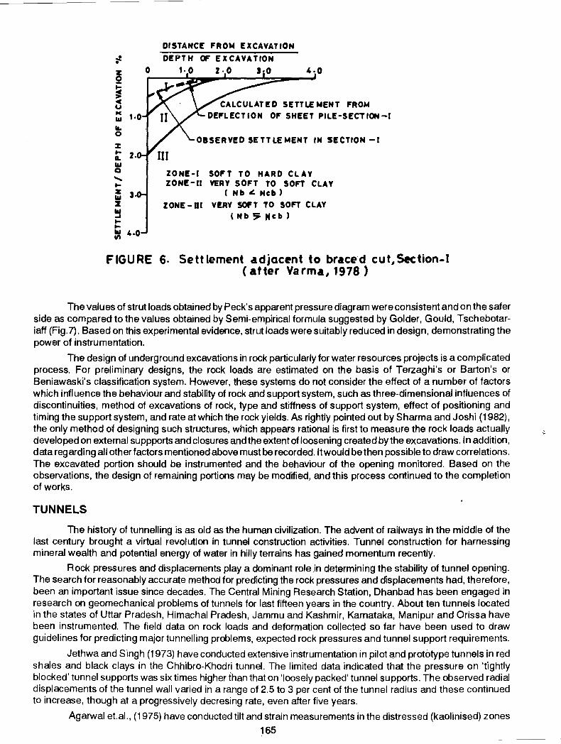
Varma (1978) has reported observations on instrumented braced cuts at the MTP Calcutta and compared results with the theoretical values. The recorded lateral deflections of sheet pile in section I presented in Fig.5. The surface settlement adjacent to braced cut is shown in Fig.6. The nature of soil strata and deflection pattern of sheet pile show that the depth of significant movement of soil is about 1 .25 times the depth of cut. With this evidence, strut loads were calculated using the method suggested by Sjerrum et al., (1972). The surface settlement and lateral deflection of pile was correlated and the-formula suggested by Gaspe (1966) was found valid.
163
..... z: ... X ... _, 2 r:: ... Ill
t.. 3
(A)
HEIGHT 0 F FILL IN METRE~
..... z x 1 .... _, ..... ..... ... Ill
0 20 40 80 100
DAI'I
l B)
FIGURE 3. v~rtical compr~ssion curv~s (A) cor~,(B}sh~ll (aft~r Varma and Raj, 1978)
EL 372·50
50 4030 2010 0 20 30 10 0
(A) (B) DISPLACEMENT IN CMS.
DOWN STREAM
FIGURE 4. Horizontal displac~ments, Ramganga Dam (at t~r Varma and Raj , 197 8)
164
1/1 km. 1.7U5
1~~~hr~~.,~
Cl z
2
"' " Ill
"' ... Ill :1
"' % 1 ... 0.. Ill Cl
POSITION ON 21. 6·77
POSITION ON 30·4 ·77
DEPTH OfF CUT:IO • 5 m ON 21.6,77
100 200 300 DISPLACEMENT IN mm
FIGURE 5. Shut pit~ d~fl~ction, S~ction ( att~r Varma, 1978)
i-
~ ... ~ c u llC 1&1 1&. 0
% ... L 1&1 Q ...... ... z 1&1 z ~ ... ... 1&1
"'
0
2.
3
CALCULATED SETTLEMENT FROM DEI'LECTION Of' SHEET PILE-SECTION-I
OBSERVED SETTLEMENT IN SECTION -1
ZONE-I SOFT TO HARD CLAY ZONE-II VERY SOFT TO SOFT CLAY
( Nb ~ Ncb)
ZONE- Dl VERY SOFT TO SOFT CLAY (Nb5PNcb)
FIGURE 6. Settlement adjac•nt to braced cut,Section-1 ( atter Varma, 1978 )
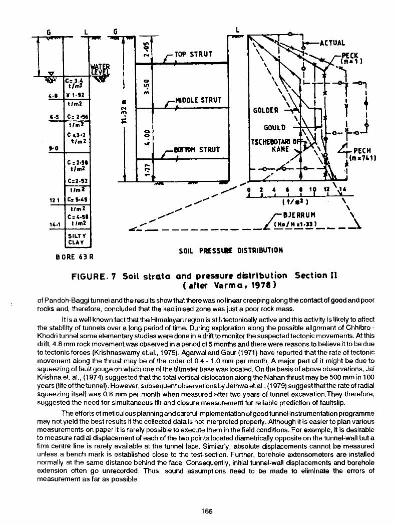
The values of strut loads obtained by Peck's apparent pressure diagram were consistent and on the safer side as compared to the values obtained by Semi-empirical formula suggested by Golder, Gould, Tschebotariaff (Fig. 7). Based on this experimental evidence, strut loads were suitably reduced in design, demonstrating the power of instrumentation.
The design of underground excavations in rock particularly for water resources projects is a complicated process. For preliminary designs, the rock loads are estimated on the basis of Terzaghi's or Barton's or Beniawaski's classification system. However, these systems do not consider the effect of a number of factors which influence the behaviour and stability of rock and support system, such as three-dimensional influences of discontinuities, method of excavations of rock, type and stiffness of support system, effect of positioning and timing the support system, and rate at which the rock yields. As rightly pointed out by Sharma and Joshi (1982), the only method of designing such structures, which appears rational is first to measure the rock loads actuall~' developed on external suppports and closures and the extent of loosening created by the excavations. In addition, data regarding all other factors mentioned above must be recorded. It would be then possible to draw correlations. The excavated portion should be instrumented and the behaviour of the opening monitored. Based on the observations, the design of remaining portions may be modified, and this process continued to the completion of works.
TUNNELS
The history of tunnelling is as old as the human civilization. The advent of railways in the middle of the last century brought a virtual revolution in tunnel construction activities. Tunnel construction for harnessing mineral wealth and potential energy of water in hilly terrains has gained momentum recently.
Rock pressures and displacements play a dominant role .in determining the stability of tunnel opening. The search for reasonably accurate method for predicting the rock pressures and displacements had, therefore, been an important issue since decades. The Central Mining Research Station, Dhanbad has been engaged in research on geomechanical problems of tunnels for last fifteen years in the country. About ten tunnels located in the states of Uttar Pradesh, Himachal Pradesh, Jammu and Kashmir, Karnataka, Manipur and Orissa have been instrumented. The field data on rock loads and deformation collected so far have been used to draw guidelines for predicting major tunnelling problems, expected rock pressures and tunnel support requirements.
Jethwa and Singh (1973) have conducted extensive instrumentation in pilot ~nd prototype tunnels in red shales and black clays in the Chhibro-Khodri tunnel. The limited data indicated that the pressure on 'f1ghtly blocked' tunnel supports was six times higher than that on 'loosely packed' tunnel supports. The observed radial displacements of the tunnel wall varied in a range of 2.5 to 3 per cent of the tunnel radius and these continued to increase, though at a progressively decresing rate, even after five years.
Agarwal et.al., (1975) have conducted tilt and strain measurements in the distressed (kaolinised) zones
165
G
4·1 tlm2 • N
"" 6·5 C: 2•56 . -t/m2 -Cd•2
t1m2 •o
c :2•11 t/m2
C:2·52 tim
12 1 C: 5·45
11m2 C: 4·51
14·1 t 1m2
SILTY CLAY
"' 0 • N
0
"' . ""
0 0 . ... ,.. r: -
TOP STRUT
MIDDLE STRUT
I
GOULD o-l~J I
4,PECH A (m•741)
·I
SOIL PR£SS\R€ DISTRIBUTION 8 ORE 63 R
FIGURE. 7 Soil strata and pressure distribution Section II ( •fter Varma, 1978)
of Pandoh-Baggi tunnel and the results show that there was no linear creeping along the contact of good and poor rocks and, therefore, concluded that the kaolinised zone was just a poor rock mass.
It is a well known fact that the Himalayan region is still tectonically active and this activity is likely to affect the stability of tunnels over a long period of time. During exploration along the possible alignment of ChhibroKhodri tunnel some elementary studies were done in a drift to monitor the suspected tectonic movements. At this drift, 4.8 mm rock movement was observed in a period of 5 months and there were reasons to believe it to be due to tectonio forces (Krishnaswamy et.al., 1975). Agarwal and Gaur (1971) have reported that the rate of tectonic movement along the thrust may be of the order of 0.4- 1.0 mm per month. A major part of it might be due to squeezing of fault gouge on which one of the tiltmeter base was located. On the basis of above observations, Jai Krishna et. al., (197 4) suggested that the total vertical dislocation along the Nahan thrust may be 500 mm in 100 years (life ofthe tunnel). However, subsequent observations by Jethwa et. al., (1979) suggestthatthe rate of radial squeezing itself was 0.8 mm per month when measured after two years of tunnel excavation. They therefore, suggested the need for simultaneous tilt and closure measurement for reliable prediction of faultslip.
The efforts of meticulous planning and careful implementation of good tunnel instrumentation programme may not yield the best results if the collected data is not interpreted properly. Although it is easier to plan various measurements on paper it is rarely possible to execute them in the field conditions. For example, it is desirable to measure radial displacement of each ofthe two points located diametrically opposite on the tunnel-wall but a firm centre line is rarely available at the tunnel face. Similarly, absolute displacements cannot be measured unless a bench mark is established close to the test-section. Further, borehole extensometers are installed normally at the same distance behind the face. Consequently, initial tunnel-wall displacements and borehole extension often go unrecorded. Thus, sound assumptions need to be made to eliminate the errors of measurement as far as possible.
166
FOUNDATIONS
FOOTINGS AND RAFTS
Footings and rafts constitute most common kinds of conventional foundation types and their designs are recognised as matters of routine. With the shift of focus to viewing structure-foundation-soil as a system and accepting the reality of interaction between them, the field monitoring through instrumentation has assumed special significance. The need for instrumentation has also been felt in studying the effect of the relative rigidity of foundation-soil systems. Bhandari and Rao {1977}, for ·example, report the field measurements of contact pressures for rafts of different relative rigidities and compare the results with contact pressures estimated by using Finite Difference Method.
For conventional footings, the Indian Standards Code of Practice permit a maximum of 60 mm of settlement and it is still an unsolved problem in soil mechanics as to how to relate total settlement to differential settlement which in fact governs the behaviour of the structure. This is the reason that measurement of settlement, for many years, has been an established practice in the study of foundation behaviour. Yet another reason for monitoring settlements has been to check the validity of different methods of settlement prediction.
Shell foundations, hyperboloid footings, skirted foundations, grid mats are all new concepts and their field behaviour is still a matter of engineering judgement without backing of field data. Since such foundations may provide an intermediate stage between simple footings and rafts or pile, with promise of economy, it would be a good idea to invest on instrumenting them for performance studies.
PILES Of the various piling systems, cast-in-situ point bearing piles are commonly used in India. These are either
bored piles or those constructed by driven-cast-in-situ process. The quality of cast-in-situ piles has always been a matter of great concern particularly in deep deposits of soft soils. Dastidar {1974}, Kulkarni {1974}, Mohan {1981 }, Bhandari et.al., {1982} and others have presented case records of failures of driven, cast-in-place piles with reference to deep deposits of Indian marine clays. Common defects are reported to be necking or waisting of piles, defective pile bases, honey-combing and segregation and in general its deshaping along the length, {Fig.8}.
The questions arising out of the various studies are:
{1} What are the kinds of defects usually associated with piling particularly in soft clays and how could these be detected either during or after construction?
{2} Degree and implications of disturbance to ground resulting from pile installation operations.
{3} The magnitudes and spatial distribution of induced ground stresses and pore water pressures and their implications.
{4} Load Transfer Mechanism; Pile ground effect; Resistance of pile cap to vertical and horizontal forces and Time dependent behaviour of a piled foundation.
167
(5) Negative drag, its magnitude, distribution and mechanism of development.
-None of the above questions, so vital as they are to the geotechnical engineer, could be truly answered without recourse to instrumentation.
For bored piles exceeding 75 em, some codes (AS 2159-1978) insist on visual inspection by sending a diver down the pile hole clearing it for concreting. Use of TV camera is also getting common to clearly view and record on a video-tape if pile base is fouled by soil debris, Holden (1980). Defective pile concrete could be detected by ultra-sonic pulse method (Rajagopal and Jai Prakash, 1975). A device, developed by the Royal Norwegian Council for Scientific and Industrial Research is capable of testing pile upto depths of 50 m or mo're. Testconsult Limited, UK also offers similar equipment commercially. The firm also market equipment for vibration testing of piles. It is reported that piles of over 40 m length and 2m diameter have been successfully tested by the vibration method. Davis and Dunn (197 4), and Higgins and Robertson (1979) have discussed the method in great details.
Degree and implications of disturbance to ground resulting from pile installation operation is no doubt broadly understood but instrumentation for obtaining direct evidence of damage to the fabric of clay (remoulding effects) and of development of excess pore water pressure is sadly lacking. It is of considerable practical value to know the manner in which degree of disturbance depend on soil type and method of pile installation. In the case of bored piles, the zone of disturbance is usually believed to be thin and effect of relief of stress nominal, provided of course, concreting is not delayed. In the case of driven piles, the zone of disturbance is usually believed to be one pile diameter around the pile (Vesic, 1977). The question therefore arises if it is really so and to what implications?
It is common knowledge that very high porepressures develop around a pile when driven in a deep deposit of saturated clay. Field measurements suggest that, for normally consolidated clays, the pore pressure increase between the pile is about 1.0 to 2.0 times effective over-burden pressure and about 5 to 7 times the undrained
TABLE 5
PREDICTED PORE PRESSURES FOR MARINE CLAYS AT THREE SITES
Indian Marine Clay Predicted Pore Pressure
Vizag Clay
(WL = 65- 97; WP = 40- 45}
w = 80-90
Cochin Clay
(WL = 109; WP = 40; W = 75}
Kandla Clay
(WL = 55 - 80; WP = 20 - 35; W = 30- 75)
f(oVo') f(Cu)
1.01- U50nV' 5.5- 6.8 Cu 0
0.97- 1.25 ll v . 5.8- 7.09 Cu 0
5.57- 5.93 Cu
shear strengths. Bhandari and Chandra Prakash (1982) have quoted over a dozen field case records on which the above reported range of values are based. The estimates for Indian Marine clays are reported in Table 5. These must be verified by taking up further work in this direction.
Load transfer mechanism of a pile has always been of considerable interest. Pile instrumentation in India has been limited to use of resistance strain gauge load cells forming an integral part of the reinforcement cage. Such studies have been reported by Asia Foundation Construction Co., Bombay and the Central Building Research Institute, Roorkee with only partial success. Apart from the 'zero drift' and other problems usually associated with the under water measurements on resistance strain gauge load cells (particularly in the long term) difficulties were encountered in estimating the elastic modulus of pile concrete, necessary for working out the lo'ad transfer at a pile depth. The Central Building Research Institute, Roorkee jointly with the Building Research Establishment, UK are now employing vibrating wire load cells with considerable innovation in the method of pile casting. Several trials have already been completed with total success and the work continues to be in progress, (CBRI Annual Report 1981). There is a very strong case to initiate instrumentation oriented studies to understand better the ground disturbance due to piling, load transfer through piles and the contribution of pile cap.
Full scale studies on instrumented piles for evaluating negative drag are also rare in India. Mohan (1981) has reported on the first study conducted on an instrumented bored pile, 66cm diameter and 20m long, cast in
168
soft clay of Visakhapatnam. Many more studies of this kind are necessary before definitive conslusions could be drawn to aid design.
GROUND IMPROVEMENT While piling continued to be the dominating mode of supporting structures in weak soil, ground
improvement offered a viable alternative to piling in many situations. Use of sand drains for improving soft clay was started in the United States in 1934 and thousands of sand drains were installed for the construction of road embankments, over deep beds of soft clay in parts of USA. Soon, cardboard wicks, geodrains, sandwicks, rope drains and a host of other kinds were developed. These substantially replaced large diameter sand drains for improving soft clays.
Sand drains have been used in India for the approach embankments of the Mahim Creek bridge, Eastern Express Highway, Vizag Ore Handling Yard and a very large number of other structures founded on soft clays. The most common form of field observations on these sites have been of settlements and ground water pressures. For example, Dastidar et. al., (1969) reportect settlement observations under preloading priqr to construction of a building foundation. Observed settlements compared well with the predicted values giving a great deal of confidence to the designer. At the outer Harbour Project in Vizag, piez-ometers, settlement gauges and slope indicator tubes were installed to obtain a true picture of time dependent stress-deformation behaviour of the soft clay deposit and to obtain realistic estimates of gain of strength with consolidation, Natarajan et. al., (1976). Other notable field monitoring has been by Datye and Nagaraju (1975) to evaluate the efficacy of 40 em diameter sand drains placed 1 .45 m apart for supporting tanks at Kandla. Based on the field observations, the estimate of permeability ratio was revised leading to more accurate predictions of settlement rates.
Sandwicks have also been used in many projects such as for construction of building foundations at the Saltlake, Calcutta, for construction of oil storage tank foundations at the Haldia and for supporting ore-handling yard at Vizag. The economy in constructing foundations of 135 storage tanks on sandwick treated ground at Haldia alone was 50 per cent over the conventional pile supporting system (Dastidar,1982).
For improvement of cohesionless deposits, vibroflotation has been extensively used in India such as at Farakka Barrage, at Bongaigaon and host of other sites. There has, however, been no instrumentation for evaluating the degree of ground improvement excepting through comparisons of penetration records before and after densification.
In recent years, the focus seem to be shifting to ground improvement by stone columns. Some attention is also being paid to ground treatment by dynamic consolidation and lime piles.
On the whole, although ground improvement techniques are being used in a big way, their evaluation through instrumentation has been sadly lacking. Wherever used, instrumentation has helped in quantifying the benefits of ground improvement and in making better long term predictions. While the success of the techniques has generally been inferred by the satisfactory peformance of the structures, the explanation and proof of degree of stability has been possible only by recorded observations.
The need for instrumentation can never be over-emphasized in case of rather sensitive structures founded on weak soils. For example floating roof tanks limit permissible angular distorsion values to 1 in 300 or in some cases even 1 in 500 for functional reasons. It is impossible to meet this requirement with confidence without resorting to instrumentation particularly because at the present state-of-the-art, prediction methods seem to be highly primitive.
LANDSLIDES AND AVALANCHES
Instrumentation of Landslides and Avalanches is offoremost significance to India. For example, the 2400 km Himalaya has been under constant threat of mass movements of a great variety. History is witness that before Man's intervention in the eco-system, large scale crustal dislocations of rock masses did block Himalayan rivers, and snow avalanches did hurtle down the slopes in the higher Himalayas as they do now. In the recent years, however the growing scale of exploitation of natural resources, intensive construction activity and the destabilising forces of nature have combined to produce a class of problems, huge and complex, never encountered before. Implementation of a number of hydro-electrical schemes for harnessing of the enormous water potential, establishment of related industries, boosting up of agriculture growth, tourism, defence etc. have further intensified road construction activity right from foothills to altitudes upto 5000 m.
The differing geological settings and formations when exposed to varying climates, hydrological
169
conditions, rainfall, seismicity, flash floods etc. do trigger different kinds of landslides. When left uncontrolled, landslides do enlarge themselves generating more furrows, more gullies and more land slides, blocking natural drainage, uprooting trees and carrying all that would have otherwise turned green and gay by the turn of the season. Reports from Kashmir Valtey suggestthat snow avalanches often play havoc with slopes not only robbing them of beautiful pine forests but also leaving them barren and therefore more vulnerable to the on-slaught of bigger mass movements to follow, Bhandari (1980).
All this capture public imagination when lives are lost, property is destroyed and communication system is disruP,ted. Economic losses due to Indian Landslides are staggering. For example, in Sikkim alone restoration works cost Rs.140 million in 1968 and Rs. 90 million in 1973 (Chopra, 1977). Mathur (1980) puts the figure at Rs.1 000 million per annum which includes loss of productive land, property, silting of reservoirs, tourist trade and aboe all, losses of lives and vehicle hours.
The only way to economise on the cost of landslide control measures with greater assurance of safety is lo resort to the observational method of design and construction. The chief objectives of the instrumentation are to:-
(a) Determine in-situ state of stress and pore pressure conditions within a slope towards understanding the ·history of the slope.
(b) Measure rainfall, run off and evaporation to plan drainage works.
(c) Study the behaviour of an existing structure-foundation-slope system or of the unstable slope itself with a view to evaluating the need or otherwise of control measures. If the need is established, attempt is required to establish the risk potential and the nature and quantum of further instrumentation.
(d) Study the performance of a freshly disturbed natural slopes and cuttings.
(e) Evaluate efficacy of control measures.
(f) Forecast long term behaviour of slopes from short-term measurements.
(g) Unfold the mechanisms of landslides and other mass movements.
(~) Warn in advance of the possible landslide hazard.
(i) Obtain wealth of data on local. experience to aid better geotechnical correlations and judgement, and thereby advance the existing state-of-the-art.
(j) Serve as evidence in law suits.
Central Water Commission, New Delhi; Central Building Research Institute, Roorkee; Central Road Research Institute, New Delhi; Central Mining Research Institute, Dhanbad; Avalanche Research Institute, Manali are some of the premier institutions in India paying ever increasing attention to the instrumentation of landslides and other mass movements.
Our problems are, however, so big and complex that routine kind of instrumentation would not do. Large sub slope movemeots may render sensitive inclinometers worthless. Piezometer tubings may shear off and earthpressure cells may get stressed beyond the limit. Ruggedness and reliability are therefore most essential traits of instruments for landslide studies in India. Wire and rod type of extensometers have been found to be useful and so is the wire type slope surface movement measuring device, Bhandari et.al., (1980). For important freshly cut slopes on which first time slides are anticipated, sensitive inclinometers (slope indicators) may prove useful in recording pre-slide movements to serve timely warning. For slides of repetitive nature, however, it is better to rely on cruder devices, such as a train of deflection tube torpedos, to discover depth to the plane of sliding.
RETAINING STRUCTURES
Retaining structures form an important component of the overall scheme of control measures. Experiences in the Himalayan region tells us that 'gabions' or"'sausage walls' perform better than rigid retaining walls of masonry or concrete. The designs of all these retaining walls are usually made empirically with bottom widths approaching half their heights. Instrumentation is necessary to know the real earth pressure distribution behind the so called 'rigid' and 'flexible' walls and then alone scientific designs are possible.
In India, use of prestressed anchors is common to stabilise landslides. Anchors have been used with success to stabilise Khuni Nallah in Jammu & Kashmir; Micro-wave Antenna Tower supporting slopes in Kasauli; Nagjhari Power House Slopes in Karnataka. Their designs involve decisions on the fixed and the free anchors
170
lengths, amount of prestress to be given to every anchor and their spacings. At the present state of knowledge, anchors are being. designed empirically and their designs are marginally revised after load tests on experimental anchors. Instrumentation is needed to know the magnitude and distribution of induced compressive forces within the rock mass and to detect tension zones immediately behind the anchors. Instrumentation is also required to study the loss of prestress with time.
STANDARDISATION
The Indian Standards Institution (lSI) is primarily responsible for standardis~tion activity in the country. Over the period of years, it has grown to a respectable size with noteworthy reeord of performance. It comprises separate Divisional. Councils which handle standardisation in different disciplines through appropriately constituted committees and sub-committees.
The Civil Engine6ring Divisional Council functioning under the Indian Standards Institution are giving considerable attention to standardisation in Geotechnics. Of the various committees, SOC 60 deals expressly with Hydraulic Structures Instrumentation. It was constituted in 1972 .. It has so far published 9 standards (Annexure 1). BDC:39 dealing with Earthquake Engineering has added IS:4967 -1968 which deals with Seismic Instrumentation of River Valley Projects. Recently, IS has constituted a sub-committee SOC 43: 7 excusively for preparing standards on Geotechnical Instrumentation.
The future plan of the lSI envisages bringing more instruments and practices under standardisation. The International Standards Organisation has offered India the secretariat for ISO{TC 182 which will also cover, inter alia, standardisation of geotechnical instrumentation.
There is a very strong case for setting up of an Instrument Divisional Council to appreciate better the multidisciplinary facets. of instrumentation. The R&D specialists, the instrument technologists, the manufacturers, the consultants, contractors and the users must all interact adequately to produce the best results.
The present lSI practice is to invite an expert to propose a draft standard. This Is tf:len considered by appropriate committee. If approved, the draft is sent out for wide circulation and comments. The dr¢1 standard is subsequently revised in the light of the comments and the corrected version is once again considered and finally approved for publication.
Since India has a very long way to go, a suggestion could be made to accelerate the standardisation activity with promise of improved quality. The Indian Geotechnical Society or the Indian Standards ·Institution could organize one day seminars or technical group discUssions on specific themes to be brought under standardisation. Experts with sound knowledge in the discipline and with exposure to related standards from other countries should particularly be invited. The ensuing deliberations, in this way, could be expected to lay foundation on which respective 'guidelines' or 'codes of practices' could be drawn up.
MAINTENANCE MANAGEMENT
. Apart from the maintenance management in the ambit of Defence Services, we see it being ignored in every sphere such as domestic services, power distributions, roads, transport vehicles etc. However, all government-state or central; and all bodies-public or private are now realising the necessity of entering into maintenance contracts for whatever they buy. Likewise, in the field of equipments and instruments also, considerable thought is now being given to the maintenance aspect and financial provisions are being made as a matter of routine practice. This appears to be a healthy trend for a substantial amount of our capital and resources would otherwise get immobilised due to lack of proper maintenance at all levels.
In my opinion, maintenance contracts alone would not do. Preventive maintenance is equally necesary because there is no point in waiting to ask for services till a break down occurs. A stitch in.time does save a situation or opportunity otherwise lost because of shut down.
It is heartening to note that agencies like the Ministry of Transport are now providing a small fraction of funds towards upkeep and maintenance. This is only a beginning. I personaily feel that an allocation of the order of 10 per cent should be made based on the capital cost of the equipment procured to enter into maintenance contracts with the suppliers and manufacturers themselves. This would not only ensure an extended life of the equipment and saving of man hours but would also ensure improved quality of supply. This is because, if a supplier is saddled with the responsibility of preventive maintenance, they would see to it that the equipment supplied is reliable, rugged and be result-oriented. Such a step alone would improve the quality of instrumentation and equipment produced in the country.
171

Instrumentation has undergone such a degree of specialisation that it is impossible for any organisation to have maintenance and service back up facilities of their own to serve every make and type of instrument. For this reason also, the task of maintenance and servicing is best entrusted to manufacturers or their accredited agents.
An intensive follow up, trained man power for carrying out maintenance and a sense of responsibility at all. levels are equally essential.
In recent years, we know of several seminars organised in the area of maintenance management. S orne institutions have also started teaching programmes in maintenance engineering and management. Besides, service.and maintenance centres have been set up by the Central Scientific Instrument Organisation, one of the national laboratories of the CSIR, the objectives being to undertake maintenance and servicing of instruments.
Most of our universities now have instrument service centres funded by the University Grants Commission. Some of these have even centralised their facilities for sophisticated Instruments run by application technologists where major responsibilities are both operational and maintenance. Such an approach is ideally suited but one must not forget that it is ultimately the responsibility and involvement of the technologist is of prime importance.
The necessity of having refresher courses cannot be overemphasised spdcially in the area of I nstrumentation. With the strides that technology is making it is esential to keep the service and maintenance engineer totally updated with the latest improvements.
RESEARCH AND DEVELOPMENT
The promotion of research and development (R & D) in any country has to receive special attention and support for the growth of science and fechnology and for development of its resources. Sixth Five Year Plan of the Government of India (1982-86) lays special emphasis on the crucial role of Science and Technology as an instrument of socio-economic change.
The Department of Science and Technology has been assigned the special role to catalyse and promote scientific instruments using existing infra-structure in the country to the extent feasible, and by creating new mechanism and infra-structures wherever necessary. There has been significant progress in all such areas assigned to this Department.
tation: Amongst the important activities of the department, following three are of special interest to lnstrumen-
* *
*
Technology utilisation and technology transfer
Science and Technology promotional programmes, including the intensification of research in several high priority areas, taking up several new schemes such as those relating to State Science and Technology Councils support for Young Scientists etc.
Development of Instruments.
The programmes of Science and Technology promotion covers setting up sophisticated scientific instrumentationfacilittes on a regional or national basis: support for professional Science and Technology bodies and societies; assistance given for organising conferences, seminars and symposia; grants given for bringing out scientific publications on a regular or adhoc basis; and prutial financial support given to scientists for attending international conferences.
Under the special and sectoral programmes being implemented by the Department, the Instruments Development Programme, is one such programme, the first phase of which has been completed and in the second phase audio-visual equipment and instrumentation has been included as also development of certain analytical instrumentation.
We find a total absence of the recognition of geotechnical instrumentation. It is for consideration of all of us to emphasise the need of mounting such a programme on a national priority basis.
The Department of Science and Technology (DST) so far has been funding research where a multiinstitutional project exists and as far as industrial research is concerned the programmes approved have been limited to the programmes submitted by national laboratories in collaboration with public sector units. What is really needed is to throw open such funding from the DST also to the private sector recognised R & D units. If the infrastructure in the Industry has been established then there should be no hitch in accepting proposals from
172
such private sector industrial units for mounting a joint research programme with institutions, one or more, to enable a rapid development of instrumentation to be carried out. Such joint programmes are the only salvation today to make a quantum jump, if we are to diversify our instrumentation and meet the need of some of our very ambitious programmes in the field of geotechnical investigations and construction.
To establish the feasibility and the viability of such projects reviewing committees composed of manufacturers, research scientists, institutions and users could be set up associated with the production agency right from the inception of the R & D activity so that the ultimate product is available to the user with the minimum of delay and in a form and a manner that is going to be acceptable to him rather than have the product developed and then finding no use for it.
LATEST TRENDS AND PROBLEMS
TRENDS
Explosion of knowledge in various branches of Science and Technology have made a tremendous impact in shaping the style offunctioning of a geotechnical engineer of today. He has a wide range oftools and techniques to choose from towards evolving highly competitive schemes of operation, without compromise on speed and quality. The latest trend is to work with low margins of safety utilising the might of instrumentation. Naturally attempts have been made to develop new instruments of higher and higher reliability to meet the whole spectrum of geotechnical situations. Where labour is expensive, sophistication and automation seem to have known no bounds.
Since there can not be any measurement without the interaction of the instrument with the medium, all out attempts are being made to minimise ground disturbance due to installation as also the effect of presence of the instrument itself. Simultaneous measurements of various quantities such as penetFation resistance and pore pressure in a piezo-cone do provide safer and more reliable basis for attempting statistical correlations which constitute popular aids to design.
Recently, extended applications of Laser* and Radar technologies have armed the geotechnical engineers with added power to deal with specific situations.
POTENTIAL OF LASER
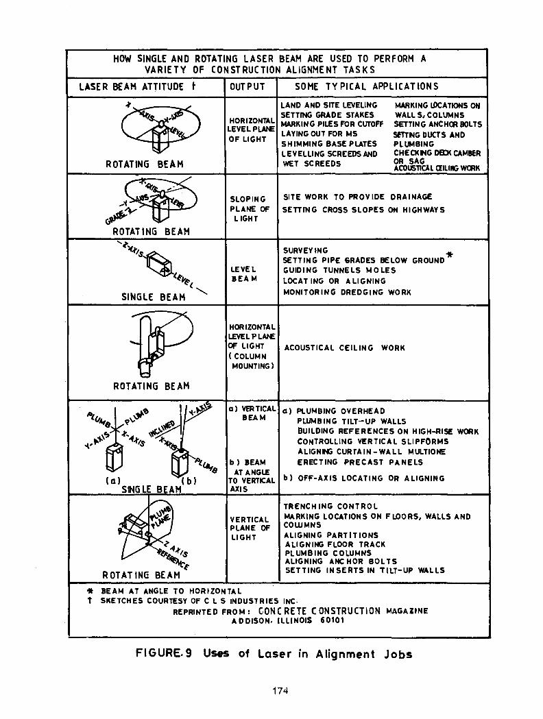
Civil Engineers are now exploiting the potential of Laser in construction of dams, aligning of tunnels, measurement of pile settlements, mechanical erection etc. In conventional surveying, the line of sight is invisible and abstract. In a Helium-Neon Laser system, it is visible and real. The positive nature of the beam provides the facility of detecting the reference point by photo-electronic sensor. The information received by the detector can be displayed or can be processed to command the operation of other equipments like paver, bull dozer, ground dumper etc. at a construction site, Sarkar and Chavda (1 981 ). Laser is to be recommended for measuring dam deflections upon changing water levels. Measurements of the movement of the crest of the Upper Glendevon Dam in Perthshire are reported by Kitching (1 973), using a technique developed by the National Physical Laboratory, UK (Harrison, Tolman and New, 1 972). Weeks and Dixon (1 973), used it for the observations of pile settlement. They were perhaps the first to combine a laser with an electro-optic detector in a manner that e!iminates the effect of tilt of transmitter on the measurement. The instrument was extremely sensitive, easy to install, simple to operate and Jess likely to be influenced by environmental changes. CLS Industries Inc. USA were the first to produce electronically levelled rotating laser, the 'AccuSweep' in 197 4. It has now become one of the standard methods of alignment used throughout the laser industry. Various practical applications are illustrated in Fig 9.
For measurements on a test pile, the reference supports are usually kept at a distance equal to fifteen times the pile diameter. If a cantilever arrangement is used the reference datum may move by 0.1 mm to 0.5 mm. or even higher at locations where temperature variations are excessive. Therefore, if the laser system is to be intrinsically more reliable than any form of beam, then it must be stable, Cooke (1 973). Kitching (Loc. cit) has concluded that errors in the movement are less than 0.5 mm. This may satisfy most practising engineers but might require improvement from research point of view. In any case, potential of laser must be exploited.
*Laser is aronym for Light Amplification by Simulated Emission of Radiation and possesses monchromatic nature, coherence and low divergence properties so much so that it radiates its energy in a nearly parallel bunch.
173
HOW SINGLE AND ROTATING LASER BEAM ARE USED TO PERFORM A VARIETY OF CONSTRUCTION ALIGNMENT TASKS
LASER BEAM ATTITUDE t OUTPUT SOME TYPICAL APPLICATIONS
ROTATING BEAM
_.., ,o/ ROTATING BEAM '-t. ~~~
~( SINGLE BEAM ""-
ROTATING BEAM
~ ~4-t,s
~I' ROTATING BEAM
HORIZONTAL LEVELPLAr£ OF LIGHT
LAND AND SITE LEVELING SETTING GRADE STAKES MARKING PILES FOR CUTOFF LAYING OUT FOR MS SHIMMING BASE PLATES lEVELLING SCREEDS AND WET SCREEDS
MARKING l.DCATIONS 0 ... WAllS, COLUMNS SETTING ANCHCJUOLTS
SfTTNG DUCTS AND PLUMBING CHECKING OED< CAMBER OR SAG ACOUSnCU aiLIIIG WCRK
SLOPING SITE WORK TO PROVIDE DRAINAGE
PLANE OF SETTING CROSS SLOPES ON HIGHWAYS LIGHT
SURVEY lNG '* SETTING PIPE 6RADES BELOW GROUND
LEVEL GUIDING TUNNELS MOLES lEA M LOCAT lNG OR ALIGNING
MONITORING DREDGING WORK
HORIZONTAL LEVEL 'PLANE
OF LIGHT ACOUSTICAL CEILING WORK (COLUMN MOUNTING)
a) VERTICAL BEAM
b) BEAM
a) PLUMBING OVERHEAD PLUMBING TILT-UP WALLS BUILDING REFERENCES ON. HIGH-RISE WORK CONTROLLING VI!:RTICAL SLIPFORMS ALIGNIJIG CURTAIN -WAll MULTIONE
ERECTING PRECAST PANELS AT ANGLE
TO VERTICAL b) OFF-AX IS LOCATING OR ALIGNING AXIS
VERTICAL PLANE OF LIGHT
TRENCH lNG CONTROL MARKING LOCATIONS ON FLOORS, WALLS AND COWMNS ALIGNING PARTITIONS ALIGNING FLOOR TRACK PLUMBING COLUMNS ALIGNING ANCHOR BOLTS SETTING INSERTS IN TILT-UP WALLS
it BEAM AT ANGLE TO HORIZONTAL 't SKETCHES COURTESY OF C l S INDUSTRIES INC·
REPRINTED FROM: C.ONC RETE ( ONSTRUCTION MAGAZINE AD DISON. ILLINOIS 60101
FIGURE. 9 Us.s of Laser in Alignment Jobs
174
POTENTIAL OF RADAR
Successful radar probings of polar ice sheets at frequency range of 30-440 MHz or of soils in the frequency range of 80-900 MHz are only two stray examples of the enormous potential georadar holds. Earth materials vary a great deal in their transparency to radar. Useful probing distance could be kilometres in glacier ice, igneous and metamorphic rocks; tens of metres in dune sands; several metres in coarse grained soils and only a few metres in clays even at frequencies as low as 1 MHz. Subsurface Interface Radar makes it possible to find stratification, ground water table and depth to bed rock.
Radar has found many successful applications. Highway engineers follow the movement of avalanches very precisely and protect highway users through radar controlled traffic lights. Mountaineers use it for locating avalanche victims as also for detecting snow bridges over crevasses. Mining engineers locate unmapped, abandoned workings using radar. Profiling of the bottom of lakes or rivers, exploration of ore bodies and locating sewer and drainage lines or buried cables are all possible through radar.
India's projected developmental activities are unlikely to spare geotechnical studies in inaccessible and less accessible areas hinting at the tremendous scope such a technology offers. The perennial hazards due to landslides and avalanches in the Himalayan belt will also find radar development of technology as an effective tool in the solution of the problem.
PROBLEMS
Of the various fresh problems, offshore geotechnics and management of nuclear wastes are discussed here.
OFFSHORE GEOTECHNICS
The search for oil and gas has extended into the vast areas of ocean, with a renewed vigour, to meet the energy crisis. Drilling in deep seas, braving severe storm and weather conditions has thus become inevitable. Experiences being gathered while erecting drilling platforms in the rough weathers of North sea, North western Atlantic, Gulf of Alaska, Gulf of Mexico and more recently in the China sea and the Bombay High have sharpened man's insatiable curosity to develop safe and more economical designs. Considering the ever increasing size of modern offshore platforms, the huge investment represent and the need to get oil wells operated quickly, the research for foundations of such structures deserves top priority. Today our limited knowledge of sea bed deposits and their questionable ability to support huge offshore structures in the offing no doubt makes us dependent on foreign expertise. A planned strategy and concerted effort is therefore necessary to achieve speedier self reliance and confidence.
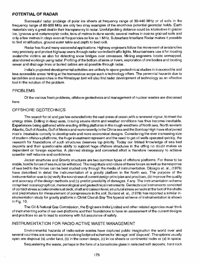
Jacket structures and Gravity structures are two common types of offshore platforms. For these to be stable, hostile forces of sea must be withstood. The magnitude and nature of these forces as well as the response of sea bed to the forces can be best studied only through the media of instrumentation. Dibiagio et. al., (1976) have described in detail the instrumentation of a gravity platform in the North sea. The purpose of the instrumentation was to (a) verify the soundness of current design principles and practices, (b) improve the quality and accuracy of the design methods and (c) predict possibility of damages, if any. The instrumentation scheme comprised oceanographical, meteorological and geotechnical instruments. Geotechnical instruments consisted of contact stress accelerometers at deck, shaft and caisson level; structural stress sensors at the foot of the shafts and piezometers for measurement of porepressure in the soil. Burland et. al., (1978) has reported a similar instrumentation study for gravity platform in Christ Church Bay The typecal scheme of instrumentation is shown in Fig. 10.
The Oil & Natural Gas Commission, the Engineers India Limited and other related agencies must think of instrumenting some of our own platforms and their foundations to have an assessment of the current designs and practices so as to lead to economy with full assurance of safety.
INSTRUMENTATION FOR RADIO-ACTIVE WASTE MANAGEMENT
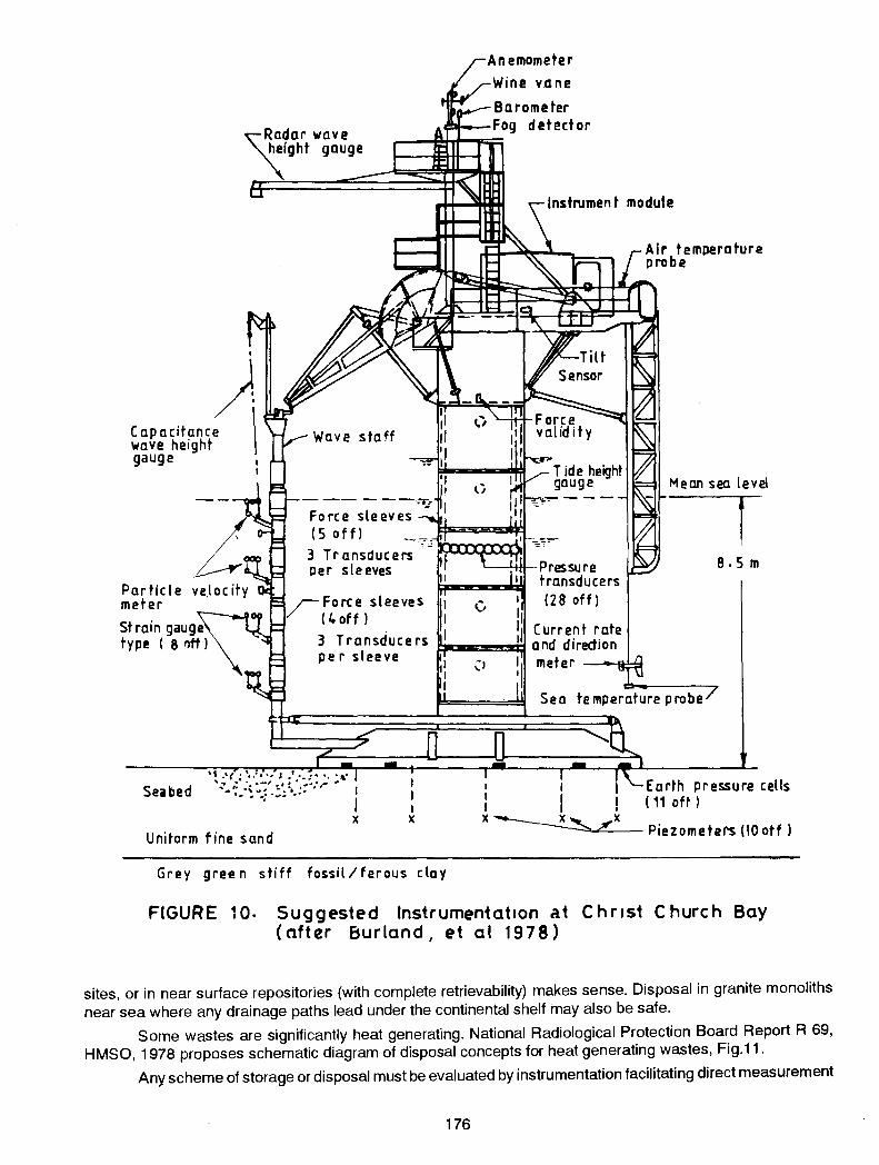
Environmental hazards of radio-active wastes have captured public imagination the world over and several countries are now serious on evotving foolproof schemes for 'storage' and 'disposal'. The options usually open are disposal (a) under land, (b) in the ocean deeps, (c) in ice sheets or continental rocks or (d) in space.
Sequestering the waste, perhaps in the form of a borosilicate glass in selected salt deposits, hard rock
175
"~~~ar wave '\.ight gauge
. )
Capacitance \ wave height gauge ,
Particle meter
I
3 Transducers per sleeves
lnstrumen t module
Mean sea level
! I
\__-4~Pressu re 8. 5 m transducers (28 off)
Strain gauge type ( 8 llft l
/Force sleeves ( 4 off)
· Current rate 3 Transducers ~-E!!!!!!!!Sij and direction per sleeve
X
Unitorm tine sand
I X
Grey green stiff fossiliferous clay
1 Earth pressure cells 1 I ! ( 11 oft ) X~ Piezometers (10 otf l
FIGURE 10. Suggested Instrumentation at Chr1st Church Bay (after Burland, et al 1978)
sites, or in near surface repositories (with complete retrievability) makes sense. Disposal in granite monoliths near sea where any drainage paths lead under the continental shelf may also be safe.
Some wastes are significantly heat generating. National Radiological Protection Board Report R 69, HMSO, 1978 proposes schematic diagram of disposal concepts for heat generating wastes, Fig.11.
Any scheme of storage or disposal must be evaluated by instrumentation facilitating direct measurement
176
SEVERAL HUNDRED I I
METERS
••••••
I I
__ --Jil.....___
II ll II II
~ ~ ~ w WASTE CONISTERS IN MATRIX OF DRILLED HOLE
PERHEPS TEN KILO-, 1
METERS ~I OR HORE ~
WASTE C ON~iT E RS IN DEEP HOLE
AGURE 11. Schematic diagram of disposal concepts for heat- generating waste. (based on Drawing in National Radiological
Production Board Report R 69. H M 5o, 1978)
FIGURE 12. Whe~l of Activities
so that if radiation levels are high, the waste could either be retrieved or treated in situ. With the advent of nuclear power plants in India, the subject deserves timely action.
CONCLUDING REMARKS
India is one of very few countries in the world to enter the field of production of geotechnical instruments over 25 years ago. It can keep pace with recent advances and· become a strong base in this important area to meet the demands of Southeast Asia and other p_arts. of the world, if expeditious steps are taken to provide the
177
necessary inputs and infrastructure. Otherwise the advantage and the fruits of whatever developments that have taken place will be lost and we may be overtaken by the other developing countries who are now fully aware of the need, potential and might of geotechnical instrumentation. This is the reason that I have chosen to speak on this subject with particular reference to India. I have also attempted to out-line the back up required for the growth of geotechnical instrument industry towards a more eventful future. The present R & D and manufacturing base needs to be strengthened by planned integration of certain progressive units (equipped with R & D centres), the National Laboratories, the Institutes of Technology and the Universities. A joint sector enterprise be set up, if necessary, with strong financial and R & D inputs to meet the countries short and long term needs.
Manufacture of geotechnical Instruments has always been a labour -intensive industry and could become a source of employment as also a substantial export earner. If tie-up can be arranged with overseas marketing and manufacturing companies who are looking for such collaborations they could provide the designs and the technology and be able to utilise the infrastructure capabilities that India can easily provide.
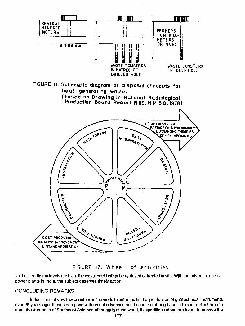
I have dealt with some major areas such as dams, underground structures, foundations, ground improvement, slopes, offshore structures etc. to highlight the importance of the subject to the geotechnical engineering profession. It is my fervent hope that the Indian geotechnical engineer would appreciate fully the entire wheel of activities (Fig. 12) and work with all possible enthusiasm to meet the challenges of tomorrow. We should resolve that hereafter we ~auld recognise instrumentation as an integral part of the practice and thus serve our chosen profession in time with the dictates of time.
Let me conclude by quoting what Terzaghi said in his Presidential address delivered at the First International Conference on Soil Mechacnis & Foundation Engineering (1936) 'Successful work in Soil Mechanics & Foundation Engineering requires not only a thorough grounding in theory, combined with an open eye for possible sources of error, sut also an amount of observation and measurement in the field far in excess of every-thing attempted by preceding generations of engineers. Hence the centre of gravity of research has shifted from the theoretical study and the laboratory into the construction camp where it will remain.' These words of wisdom are perhaps more true today than ever before.
ACKNOWLEDGEMENT
I would like to thank the Indian Geotechnical Society for the kind invitation to deliver this Annual Lecture. Dr. R.K. Bhandari, Dr.V. Sreenivasulu and Shri M.D. Nair have assisted me a great deal in preparation of the paper for which I am grateful. My thanks are also due to the authors of a large number of papers which form the basis of some of the material presented.
REFERENCES
"Anderson Ranch Dam Technical Record of Design and Construction" U.S. Bureau of Reclamation, Danver (1956).
AGARWAL, P.M., GAUR, V.K. (1971), "Study of Crustal deformations in India" Tectonophysics, pp.287-296.
AGARWAL, P.N., KUMAR, V., KULSHRESHTA, V.K. (1975), "Final report on Measurements of Vertical and Horizontal Displacements in the distressed reach of Pandoh-Baggi Tunnel", EO. 75-10, Department of Earthquake Engineering, University•of Roorkee, Roorkee p. 10.
BHANDARI, R.K. and RAO, A.:.R.K. (1977),"Conce.,pt of Rigidity in Foundation Analysis."
Proc. Int. Symp. on Soil Structure Interaction, Roorkee, Vol. 1. pp. 287-294.
BHANDARI, R.K. (1980), "Landslides in Himalaya-problems, causes and cures", Proceedings, UNESCO's Alma Ata Seminar on Landslides and Mud Flows, USSR, October.
BHANDARI, R.K., CHANDRA PRAKASH a'nd SHARMA, A, (1982), "Failures in cast in place piles." Proceedings, Conference lnternationale de Mecanique Des Sols, Mexico (1957-1982 Commemorative Volume) p.125.
BJERRUM, L. FRI MANN, C. and DUNCAN, J. M. (1972), "Earth pressure on Flexible structure"-state of Art Report, Fifth European conf. on SM & FE, Madrid.
BURLAND, J.B., PENMAN, A.D.M. and GALLAGHER, K.A. (1978), "Behaviour of a Gravity Foundation Under Working and Failure Conditions", European Offshore Petroleum Conference and Exhibition, London.
GASPE, M.S. (1966), "Surface settlement adjacent to brased cuts", Proc. ASCE, Vol. 92, SM4.
CAHPRA, B.R. (1977), "Landslides and other mass movements along roads in Sikkim and North Bengal." Symp. on Landslides and other mass movements, Bullettin, Int. Association of Engineering Geology Prague (Czechoslovakia), 15-16 Sept. ,pp.162-166.
178
COOKE, R.W. (1973}, "Discussion on Laser Device," Proceedings, Field Instrumentation in Geotechnical Engineering. Symposium, organised by BGS 30 May -1 June, p. 572.
COOLING, L.F. (1973}, "Field Instrumentation in Geotechnical Engineering" Sym. British Geotechnical Society, 30 May, Closing address, pp. 708-710.
DASTIDAR, A. G. (1974} "Application of Soil Mechanics--with particular reference to problems in India", Journal ofiGS, Vol. 4, No. I, pp. 1-38 ..
DASTIDAR, A. G., GUPTA, S. and GHOSH, T.K. (1969}, "Application of Sandwick in a Housing Project", Proc. Seventh Int. Conf. on Soil Mech. & Foundation Engg., Mexico, Vol. 2, pp. 59-64.
DASTIDAR, A. G. (1982}, "East Coast Constructions Endowment Lecture" College of Engineering, Guindy, Feb.
DATYE, K.R. (1968}, "Detailing Earth Dams to minimise cracking hazards", Proc. Symp. on Earth and Rockfill Dams, Nov., pp. 269-278.
DAVIS, A. G. and DUNN, C.S. (1974}, "From Theory to field experience with non-destructive vibration testing of pipes", Proc. lnstn. of Civ. Engrs., Pt. 2, pp. 571-593.
DIBIAGIO, E. MYRVOLL, F., and BORG HANSEN, S. (1976}, "Instrumentation of Gravity Platforms for Performance Observations", Conference on the Behaviour of Offshore Structures, BOSS, Trondheim.
DIBIAGIO, E and MYRVOLL, F (1981}, "Field Instrumentation for Soft Clay" Soft Clay Engineering, Ch. 10.
HARRISON, TOLMAN and NEW (1972}, Proceedings, ICE, 52 (May}, pp.1-24.
HOLDEN, J.C. (1980}, "Development of a socket Inspection Device", Int. conf. on Structural Foundation on Rock, Sydney 7-9 May, Vol.2.
JAIKRISHNA, ARYA, A.S., AGARWAL, P.N., CHANDRA, B. and SINGH, V.N. (1974), "Final Report-Investigation of Kroi-Nahar Intra-thrust Zone," Yamuna Project Report, E0-4, Earthquake Engineering Dept., University of Roorkee, p.16.
JEEBALA RAO, D. and KUMAR RAO (1968}, "Movement in some Earth Dams during and after construction",proc. Symposium on Earth and Rockfill Dams, Nov. Vol. 1, pp. 145-151.
JENA, A.B. and DAS, G.N. (1968}, "Performance of Hirakud Earth Dam" Proc. Symp. on Earth and Rockfill Dams, Nov., Vol. 1, pp. 152-161.
JETHWA, J.L., and SINGH, 8 (1973), "Instrumentation for Evaluation of Rock loads in the Intra-Thrust zone at Kalawar Head race Tunnel of Yamuna Hydro-electric Scheme, stage II, part II", Symp. on Rock Mechanics & Tunnelling problems, Kurukshetra.
JETWA, J.L., SINGH 8., BHAWANI SINGH and MITHAI, R.S. (H?79}, "Influence of Geology of Tunnelling Conditions and Deformational behaviour of supports in the Faulted Zones"--- A case history of Yamuna Hyde I Tunnel in India (under publication).
KITCHING, B.W. (1973), "Discussion, Laser for Measurement of the movements oft he crest of upper Glendevon dam in Perthshire," Proceedings, Field Instrumentation in Geotechnical Engineering, Symposium organised by BGS, 30 May,-1 June, p.570.
KRISHNASWAMY, V.S., KUKKU, S.M. and AGARWAL, A.N.1975, "A comparative reviewoftheforecastandtheactual tunnelling conditions in the Pandoh-Baggi and Sundernagar-Sutlej Tunnels", Proc. of Symp. on Tunnelling Techniques, Equipment and Tunnelling Experience, April, Sundemagar, Vol. I.
KULKARNI, N.N. (1974} "Presentation, Seminar on Pile Foundations. Corrosion, Detailing and Ground anchors", Tech. session 1-pile Foundation systems, Sept., pp. 79-81.
Li, C. Y. (1959), "Construction Pore Pressures in Quebra dona Earth Dam, Journal, Soil Mechanics & Foundation Division, American Society of Civil Engineers, Oct., p. 43.
MATHUR, H.N. (1981}, "Influence of Human Activities on Landslides Mudflows and Slope Movements in India and Efforts at Reducing their Negative Impact", Proceedings of UNESCO Seminar on Landslides and Mudflows, Alma Ata, USSR.
MOHAN DINESH (1981}, "A close look at problems of Research and its application to Pile Foundations", IGS Annual Lecture, Indian Geotech. Journal Vol. II No. 1, pp. 1-40.
MURTHI, P.L.N., TIWARI, J.M. and TIWARI, P.C. (1968}, "Pore Water Pressure in Earth Dams during construction", Proc. Symp. on Earth and Rockfill Dams, Nov., pp. 256-263.
NATARAJAN, T.K., BHANDARI, R.K and SREENIVASULU, V. (1976), "Foundation lnstnJmentation at Outer Harbour in Vizag", Proc. Symp. on Foundations and Excavations in Weak Soil, Calcutta, Vol. I, pp. 36-44.
RAJAGOPALAN, P.R. and JAI PRAKASH (1975}"Non-destructive Fiek:ITestofConcrete Foundations", Proc. ofRILEM Second Int. Symp. on New Developments in Non-destructive Testing of Non-metallic Materials, Bucharest, Sept., Vol. 3, pp. 81-86.
SAINI, S.S. and CHANDRASEKARAN, A.A. (1968}, "Effect of core on Earthquake response of failure for C~ Soils", Proc. Symp. on Earth and Rockfill Dams, Nov., pp. 25-38.
179
SALDANA, EC. and UGADE, D.G. (1968}, "Field Measurements at Bor Earth Dam", Proc. Symp. on Earth and Rockfill Dams, Nov., pp. 171-178.
SARKAA, G. G. and CHAVADA, D. (1981}, "Use of Laser Systems in Dam Construction and Tunnelling", Post. sess. proc. Vol, II of Seminar on Accelerated Hydroelectric Development in India, May, T. 27-33.
SHARMA, V.M. and JOSHI, A.B. (1982), "The need of Instrumentation in underground openings" CBIP publication No. 159, Vol. 1.
STRANGE, W.L. (1898), "Reservoirs with high earthern dams in Western India", Min. Proc. lnstn. Civ. Engrs. pp. 130-199.
~ERZAGHI, K.VON (1936), "Stability of slopes on natural clay" Proc. ist Int. conf.soil mech., Horvard 1, pp. 161-165.
VARMA, R.K. and RAJ. B.B., (1978), "Performance Analysis ofEmbanklllP.nts-core studies", Proc. Geotech India, Dec, Vol. I pp. 114-119.
VARMA, R.N. (1978), "Soil Investigation in braced cuts MTP Calcutta," Proc. Geotech-lndia, Dec. Vol. 1, pp. 366-372.
VESIC, ALEXANDER,S. (1977), "Design of Pile Foundations" Transportation Research Board, Washington D.C. publication, National Cooperative Highway Research Program Synthesis of Highway Practice No. 42.
WEEKS, A G., and DIXON, R.B. (1973), "Some new techniques in field instrumentation applied to a bored pile trial in Gault clay" Proc. Symp. British Geotechnical Society, pp. 423-436.
ANNEXURE 1
BDC:60 Hydraulic Structures Instrumentation.
Published Standards
IS: 6524-1972 Code of practice for installation and observation of instruments for temperature measurement inside dams: Resistance type thermometets
IS: 6532-1972 Code of practice for design, installation, observation and maintenance of uplift pressure pipes for hydraulic structures on permeable foundations.
IS: 7356 (Part 1)-1974 Code of practice for installation, maintenance and observation of instruments for pore pressure measurements in earth dams: Part I Porous tube piezometers.
IS: 7356 (Part 11)-1976 Code of paractice for installation, maintenance and observation of instruments for pore pressure IT!easurements in earth dams: Part II Twin tube hydraulic piezometers.
IS: 7436(Part 1)- 1973 Guide for types of measurements for structures in river valley projects and criteria for choice and location of measuring Instruments: Part I For earth and rockfill dams.
IS: 7436 (Part II}- 1976 Guide for types of measurements for structures in valley projects and criteria for choice and location of measuring instruments: Part II Concrete and masonry dams
IS: 7500-1974 Code of practice for installation and observation of cross arms for measurement of internal vertical movement in earth dams
IS: 8226-1976 Code of practice for installation and observdtion of base plates for measurement offoundation settlement in embankments.
IS: 8282 (Part 1)-1976 Code of practice for installation, maintenance and observation of pore pressure measuring devices in concrete and masonry dams: Part I Electrical resistance type cell.
180