Embed Size (px)
Citation preview

NCC 1701 Technical Report
Bottom, From Left to Right: Laxmi Dongur (Production Engineer), Sarah Haw-man (Safety Inspector), Mackenzie Hitz (Marketing Representative), Zane Holmstrup (R&D Technician), James Williams (Lead Design Engineer).
Top, Left to Right: Tara Scott (Director of Marketing), Mikayla Wensel (Design Engineer), Connor Wilkinson (Lead Production Engineer), Travis Huffmaster (CFO/ Director of R&D), Evan Hawman (Project Manager), Michael Streitweiser (Design Engineer), Hunter Heaton (CEO/Electrical Lead), Bill Montana (Director of Human Resources).
Not Pictured: Mark LeGros (R&D Technician)
Mentors: Bill Montana and Tara Scott
Coppell High School Coppell, Texas USA Texas Regional (Houston)
Inside is Hydro-Development Systems’ technical report for the company’s latest ROV, Olive. It covers the design process for the robot, the functions of the attachments, concepts considered, troubleshooting, company tions, challenges, and the project budget.
Nautical ity Craft 1701-Damage Control variant, “Olive”

NCC 1701 Technical Report
Page | 2
Table of Contents
Abstract ....................................................................................................................................................... 3
The Company .............................................................................................................................................. 3
Design Rationale ......................................................................................................................................... 4
Task 1 ....................................................................................................................................................... 5
Task 2 ....................................................................................................................................................... 5
Task 3 ....................................................................................................................................................... 6
The Mobile Deployment Platform .......................................................................................................... 7
Controls................................................................................................................................................ 7
Cameras and Monitors ........................................................................................................................ 8
Stability and Balance ............................................................................................................................... 8
Thrusters ................................................................................................................................................. 8
Interchangeable Parts ............................................................................................................................. 9
Electrical Design Rationale ........................................................................................................................ 10
Design Points ......................................................................................................................................... 10
Motor Control ....................................................................................................................................... 10
Relay Use ............................................................................................................................................... 11
Electrical Safety ..................................................................................................................................... 11
Safety Features ......................................................................................................................................... 13
Challenges ................................................................................................................................................. 13
Troubleshooting Techniques .................................................................................................................... 15
Future Improvement ................................................................................................................................. 16
Reflections & Lessons Learned ................................................................................................................. 16
Budget ....................................................................................................................................................... 18
Acknowledgements ................................................................................................................................... 19
Appendix ................................................................................................................................................... 20

NCC 1701 Technical Report
Page | 3
Abstract In response to the Deepwater Horizon oil spill in the Gulf of Mexico in the summer of 2010, the
MATE Center released a contract for companies to design and build ROVs (Remotely Operated Ve-
hicles) that would be able to respond should such a tragedy ever happen again. In the disaster, an oil
rig ruptured and sank to the bottom of the Gulf. These ROVs would be put through a series of simu-
lated tests to prove the capability of the fully-operational final product. When the contract was re-
leased by the MATE Center, Hydro-Development Systems, Inc. immediately began working on its bid.
For the past six months, the company has designed a submersible capable of completing all real-world
versions of the tasks in the simulation and built a craft to compete. The resulting craft, the Nautical Ca-
pability Craft 1701-Damage Control variant (code-named Olive)—the first of the new NCC 1700 line of
marine-grade submersibles—is equipped with an effective propulsion system capable of linear move-
ment along three axes and with up to 50° of pitch in either direction. The Aqueton™ sweeping system
pushes creatures into the capturing basket, the E-Vac™ suction system collects water sample, and a
spinning claw, designated Thortite™, deploys the Kinetic Detachable Grappling Hook (KDGH) and spins
the valve wheel.
Inside is Hydro-Development Systems’ technical report for the company’s latest ROV, Olive. It
covers the design process for the robot, the functions of the attachments, concepts considered, troub-
leshooting, company reflections, challenges, and the project budget.
The Company Hydro-Development Systems, Inc was founded on Oc-
tober 5, 1992 in Coppell, Texas; a seemingly insignifi-
cant event for the marine technology industry. Now,
after 18 years and six highly successful ROV lines in
the Nautical Capability Craft series, Hydro-
Development Systems, Inc. has become an industry
leader and creates products known and renowned the
world over. With so many hard-working businesses
across the globe depending on the products we
create, the creation of our seventh line must continue
this tradition of excellence. Special care was taken with
the first in this new 1700 line, the NCC 1701. Lives, livelihoods, and the environment will depend on
this ROV’s continued success every day of the year.
Figure 1- Hydro-Development Systems' first factory (Circa 1994)

NCC 1701 Technical Report
Page | 4
Design Rationale
The MATE Center presented the team with a challenge: simulate what the fully functional NCC
1701 would be required to do. The company created a test platform, Olive, to perform these similar
objectives in order to demonstrate the capabilities of the NCC 1701.
The objective was to design and develop a system that:
Is safe to operate
Is inherently stable
Is positively buoyant, with an highly ad-
justable ballast system
Is intuitive to operate
Is maneuverable, with a high level of me-
chanical dexterity
Has enough thrust to develop reasonable
speed
Has good vision for pilot’s
Utilizes modular components for plug-and-
play capabilities
Is flexible in nature, for rapid prototyping and modification
Is made from readily available materials
Is reliable as demonstrated with testing
Figure 2- The NCC 1701, Olive
NCC 1701 Technical Report
Page | 5
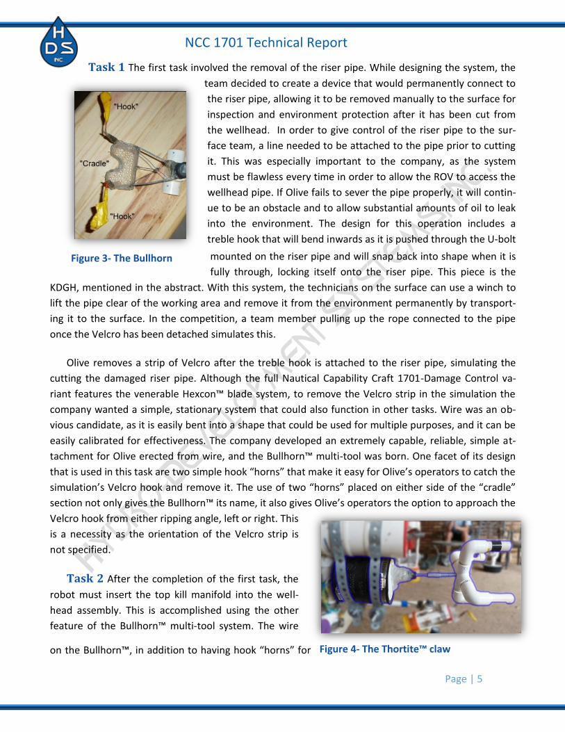
Task 1 The first task involved the removal of the riser pipe. While designing the system, the
team decided to create a device that would permanently connect to
the riser pipe, allowing it to be removed manually to the surface for
inspection and environment protection after it has been cut from
the wellhead. In order to give control of the riser pipe to the sur-
face team, a line needed to be attached to the pipe prior to cutting
it. This was especially important to the company, as the system
must be flawless every time in order to allow the ROV to access the
wellhead pipe. If Olive fails to sever the pipe properly, it will contin-
ue to be an obstacle and to allow substantial amounts of oil to leak
into the environment. The design for this operation includes a
treble hook that will bend inwards as it is pushed through the U-bolt
mounted on the riser pipe and will snap back into shape when it is
fully through, locking itself onto the riser pipe. This piece is the
KDGH, mentioned in the abstract. With this system, the technicians on the surface can use a winch to
lift the pipe clear of the working area and remove it from the environment permanently by transport-
ing it to the surface. In the competition, a team member pulling up the rope connected to the pipe
once the Velcro has been detached simulates this.
Olive removes a strip of Velcro after the treble hook is attached to the riser pipe, simulating the
cutting the damaged riser pipe. Although the full Nautical Capability Craft 1701-Damage Control va-
riant features the venerable Hexcon™ blade system, to remove the Velcro strip in the simulation the
company wanted a simple, stationary system that could also function in other tasks. Wire was an ob-
vious candidate, as it is easily bent into a shape that could be used for multiple purposes, and it can be
easily calibrated for effectiveness. The company developed an extremely capable, reliable, simple at-
tachment for Olive erected from wire, and the Bullhorn™ multi-tool was born. One facet of its design
that is used in this task are two simple hook “horns” that make it easy for Olive’s operators to catch the
simulation’s Velcro hook and remove it. The use of two “horns” placed on either side of the “cradle”
section not only gives the Bullhorn™ its name, it also gives Olive’s operators the option to approach the
Velcro hook from either ripping angle, left or right. This
is a necessity as the orientation of the Velcro strip is
not specified.
Task 2 After the completion of the first task, the
robot must insert the top kill manifold into the well-
head assembly. This is accomplished using the other
feature of the Bullhorn™ multi-tool system. The wire
on the Bullhorn™, in addition to having hook “horns” for
Figure 3- The Bullhorn
Figure 4- The Thortite™ claw

NCC 1701 Technical Report
Page | 6
removing the riser pipe, also includes a cradle for the PVC T-joint that holds the manifold at its
original 45-degree angle. The cradle, coupled with the fine-tuned motor control provided by speed
controllers, allows Olive to simply scoop up the manifold with the Bullhorn™. Placement of the top kill
manifold is just as easy. Olive simply positions the tip of the device in the receptacle and then drops
down, releasing the manifold. After the manifold is successfully inserted, the ROV spins the valve
wheel to shut off oil flow. One solution to this problem stood out to the design team; that of a rotating
claw with four arms that is inserted into the valve wheel and spun. The implementation was difficult
because a very sturdy system was required. This was eventually delivered in the form of the Thortite™
claw after dedicated work and perseverance. Once turned off, a rubber PVC cap must be placed on top
of the pipe as the last insurance against further oil leakage. The rope handle on the cap is held by the
robot’s simplest attachment, a hook protruding directly outward from the front of the robot. In the si-
mulation, this cap is brought down from the surface by the rover for use on the wellhead. Due to the
fine motor control granted by the speed controllers, the team is able to drop the cap onto the test pool
floor and complete the preceding tasks without the cap’s weight hindering movement, confident in
Olive’s ability to later pick up the cap with ease.
Task 3 The third task requires that a water
sample be collected from an area nearby the pipe.
This is necessary to determine current pollution le-
vels. A graph detailing the amount of oil at each
depth is provided to find the correct water sample.
When the company successfully determines the
depth needed for the sample, an Aeris ATMOS 2 in-
stalled on the robot allows it to maneuver to and
confirm the correct depth. It was determined that
the depth gauge has a few factors inhibiting its ac-
curacy so it requires a calibration chart. This chart is
calculated based on a 3% difference between salt-water and chlorine gauges and the 34cm between
the location of the depth gauge and the tip of the collection device (detailed below) on the robot.
Buckets housing a pouch full of colored sample liquid with an access port are placed at various depths
around the test field. After the bucket at the proper depth is located, a sample must be extracted and
brought into the ROV’s possession. The E-Vac™ suction system was designed, to complete this task.
The E-Vac™ consists of a bilge pump with a pipe extension on the intake valve and a length of hose
wrapped around the robot. It is designed to draw the liquid out in a concentrated sample by inserting
the pipe as deep as possible into the sample pouch reservoir and then activating the bilge pump. The
pump pulls the colored sample through a one-way valve and into the hose section of the E-Vac™ sys-
tem, bringing up to 150mL into the possession of the ROV.
Figure 5- The E-Vac™ System

NCC 1701 Technical Report
Page | 7
Task 4 For the fourth task, animals must be collected from the floor of the pool. These
represent actual animals that would be captured for testing to determine the extent of the damage on
an oceanic ecosystem. To collect the animals quickly, the team chose to make a jet stream collection
system, the Aqueton™. The system includes a thruster, essentially identical to those used for propul-
sion and maneuvering of the robot, to propel the organisms into an onboard metal basket. The system
is similar to a leaf blower, but for underwater organisms. The simplistic design also barely impedes
camera vision, affects stability very little, remains out of the way for regular operation, and, due to its
orientation, actually serves as a slight “turbo” boost if desired by the operators.
The Mobile Deployment Platform
The Platform The substructure for the Mobile
Deployment Platform (MDP) is a large cart donated to us by
Coppell High School’s Engineering Department. It features
three monitors to display the camera feeds, a middle sec-
tion that houses the control board, a compartment under-
neath for tool storage, a spool for storing the tether, and a
carabineer hanging from the overhanging monitor plat-
form for safely attaching Olive.
Controls For the controls, the design team decided on a hardware-based system as opposed to
a computerized one for several reasons. It was determined it would be easier to adjust a mechanical
system and immediately test than to change lines of code, compile, upload, establish a working con-
nection, and then test. Instead of wiring everything to a handheld controller, a control box was
created, built around a series of speed controllers and switches. This requires multiple drivers to oper-
ate the NCC 1701-Damage Control. The reasoning behind such a system is that with only one person,
input would come from multiple team members and monitors causing confusion for a single pilot. With
training, Olive’s operators, each op-
erating different sections of the
robot, can run the ROV as a single
entity. The three-member team
learns to assimilate the flurry of
notices and orders flying back and
forth from each member and then
amalgamate the various reactions
into highly effective robot function.
Because each component can
be moved and easily rewired on
the surface, the group does not need Figure 7- Labeled control board
Figure 6- The Mobile Deployment Platform
NCC 1701 Technical Report
Page | 8
to worry about waterproofing every component. Instead, focus can be directed to key areas
on the surface. By basing the system above water, problems can quickly be dealt with should any arise.
The speed controller system allows for very small increments of motion as well as large, faster incre-
ments (Covered in Electrical Design Rationale under “Motor Control”). Therefore, Olive is able to utilize
full power if necessary while also making fine adjustments to her heading. If weight is added to the ma-
machine mid-mission, thrusters can be trimmed in order to account for a change in weight and
buoyancy and keep the robot operating effectively. A bang-bang system has been placed as a backup
to the speed controllers to ensure robot function in the event of speed controller failure. Should such a
failure occur, the operators need nothing more than to flip a single switch to restore thruster function
using the bang-bang system.
Cameras and Monitors Four stationary cameras were placed on the robot to see all the dif-
ferent aspects without the need for swiveling. The main camera hangs off the stern-most top brace
and looks forward through the frame of robot. It has view of
the all the thrusters, the basket, the Aqueton™ tube, and
everything in front of the robot. It is used most frequently,
so it sends the video to the middle TV on the MDP where
all three pilots can see it well. Another camera looks down
the Aqueton™ pipe to align it with the access port for the
water sample. This video feed is sent to the right side TV,
so that the main pilot can line the tube up with the port
before it is dropped in. The left TV switches between two
cameras, which show the bow and stern edge views. The
front camera shows the Bullhorn™, the wellhead cap hook, and the Thortite™ alignment for the KDGH
and the valve wheel. This is only useful part of the time, so a video input toggling device allows the
camera view of the back to replace it. A camera looks down the stern edge and allows the team to find
landmarks underwater. Put in view are the Aeris ATMOS 2 (depth gauge), a level, and a compass. These
are used to give the drivers a relative sense of how the robot is sitting in the water and where it is.
Stability and Balance To keep the robot steady, a system was developed to make Olive
self-righting. Two buoyancy tubes are built into the top of the ROV and two tubes filled with weights
make up the base. These weights come in small, 4cm sections that can be easily slid into and out of the
bottom tubes to make Olive rest on a horizontal plane. Non-weighted sections of tubing are put in
around the weights to ensure that they cannot slide inside the weighting tubes. A screw topped with
an 8mm hex head closes off the weighting tubes, allowing quick and easy calibration.
Thrusters For movement, a standard thruster had to be designed and manufactured. The
team went through a testing phase to figure out what design would work best. The team started with
500 GPH Rule bilge pumps, using them just as they were and using the expelled water to push the
craft. Finding that design lacking in power, the team then modified the bilge pump by eliminating the
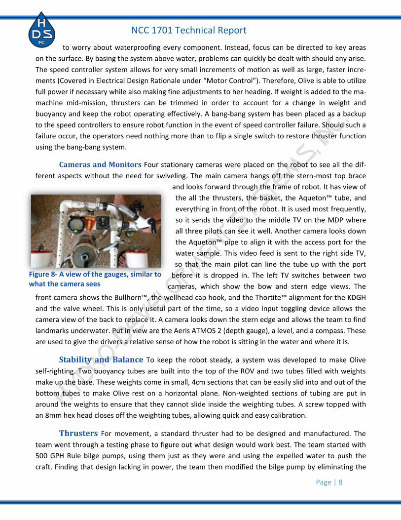
Figure 8- A view of the gauges, similar to what the camera sees

NCC 1701 Technical Report
Page | 9
white motor housing. This allowed the team to take the impeller off the bilge pump, which is
used for pushing water perpendicular to the motor, and replace it with several plastic airplane propel-
ler variants, which push water in line with the motor. These produced more force, but were inefficient
as the water caused them to bend as they are meant for air. The team did more research and found
model boat propellers, which are designed for the express purpose of pushing water in line with mo-
tors. The problem that arose was attaching the propellers to the motor shaft. The previous designs had
just slipped on to the bilge pump’s exposed axle, but the boat propellers that were purchased required
a drive dog, which have flanges that interlock with the propeller, to spin. The drive dogs do not attach
to the d-shaped shaft that the bilge pumps have. A propeller adaptor was used so that it clamped onto
the motor shaft and allowed for a 10 mm bolt to extend from it, to which the drive dog and propeller
attached. When this was implemented, the thrust was
doubled and it was decided that the propeller would be
used. The propellers came in opposite molds, one that
pushes when it turns counterclockwise and its inverse
that pushes when it turns clockwise. This is important to
know because when a propeller spins it pushes in line
with the motor, but also exerts has a small amount of
force that acts perpendicularly to the thrust direction.
This causes whatever the motor is attached to spin. If
counter-rotating thrusters are put on opposite sides of
the robot, then that spin is taken out of the robot’s
movement. Even after the implementation of the model boat propellers, more power was desired. As a
result, 1100 GPH bilge pumps replaced the 500 GPH bilge pumps on the forward-and-back and vertical
thrusters so that more power could be obtained.
To make the thrusters safer and more efficient, PVC ducts were added. A PVC duct is a piece of
2-inch PVC pipe that has a part cut out, so that a solid ring surrounds the propeller. This is connected
to two narrow strips that attach to a split ring surrounding the bilge pump. The problem with ducts is
that the motor, which the duct sends the water straight into, can restrict reverse movement. Extending
the length of the motor shaft with a longer bolt and increasing the duct length corrected for this. This
allows water to be pushed out past the motor when the propeller goes in reverse. These final thrusters
produce approximately 9.8 N of thrust.
Interchangeable Parts The final advantage of our system versus most other companies is that our
robot has a highly customizable, modular system. This system utilizes hose clamps for the mounts of
every attachment and joint on the robot. With this system, every single part of the robot can be al-
tered by a single tool – an 8mm nut driver. The system makes almost all parts universally reusable and
attachments and components can be readily changed into something radically different in a short
amount of time.
Figure 9- The thruster assembly
NCC 1701 Technical Report
Page | 10
Electrical Design Rationale
Design Points The objective was to design and develop an electrical system that:
Is safe to operate by being:
o Capable of being completely shut down by a single switch.
o Fused to protect from direct short of the battery.
o Fused for the protection of electrical components.
o Flexible in independent power switching of sub-systems.
o Laid out neatly and is clearly marked.
o Well documented.
Minimizes the size and weight of the tether by utilizing:
o Common high current power wires.
o Small, light and flexible control wires.
o Relays
Maximizes the capabilities of the thrusters by utilizing PWM speed control technology.
Flexible in nature, for rapid prototyping and modification.
Has a redundant system for reliability.
Is reliable as demonstrated with testing.
Motor Control One of the most important features of the robot is the control of the motors.
The main thruster motors—which control linear move-
movement forwards and backwards, linear movement
up and down, and pitch—are important because the
way in which they operate determines how the entire
machine moves. When the team first designed the ro-
bot, a bang-bang system was used with momentary
DPDT (Double-Pole Double-Throw) switches. “Bang-
bang” simply means that switches complete the circuit of
the motor and the battery directly, providing full, sus-
tained thrust instantaneously. This allowed Olive to move quickly and was a simple method of propul-
sion. The problem with bang-bang technology is that it results in sudden, jarring movements, which are
manageable, but smoother robot movements make it easier to guide. The electrical team looked into
speed controllers, which would allow the robot to have variable speed and not suffer the quick, jerky
motions. The part decided upon is a bidirectional speed controller, which uses pulse-width modulation
and comes from Carl’s Electronics. The team bought them as kits and assembled six; four to use and
two for spares. Building the parts, instead of buying them assembled, let the team learn how the con-
trollers work. The board serves as a comparer, taking in voltage and sending it out to a potentiometer,
which varies resistance and directs the board as to how long power should be supplied to the motors
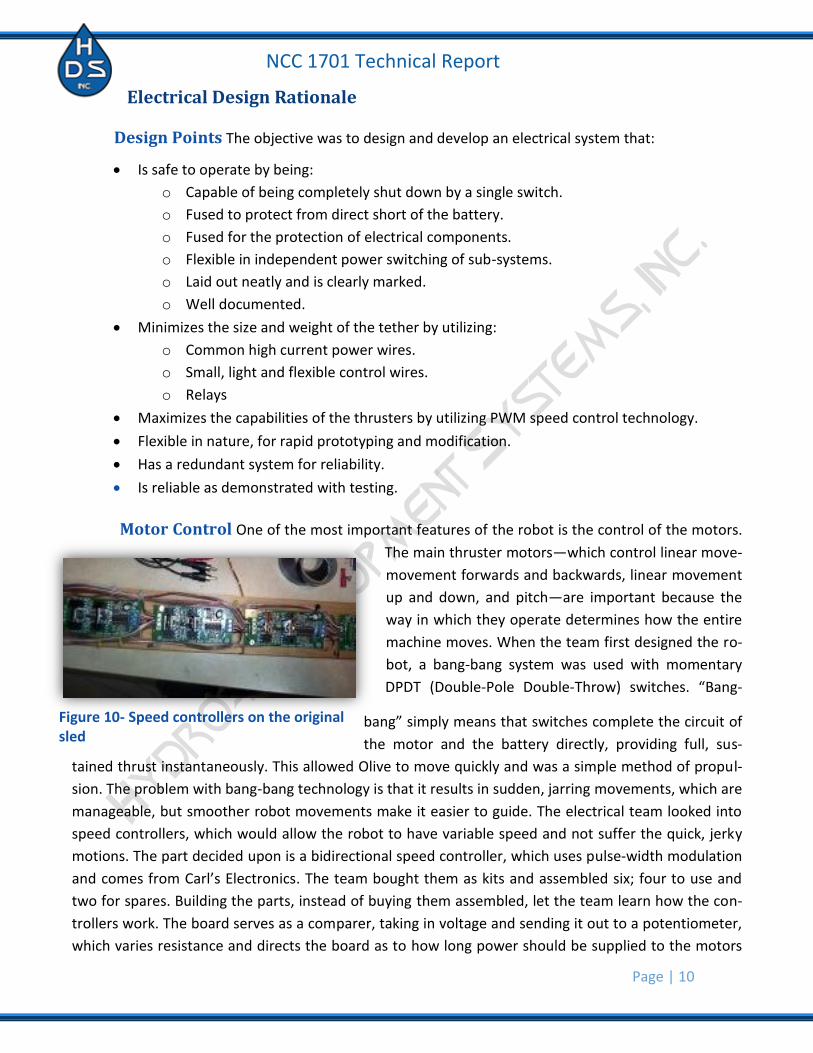
Figure 10- Speed controllers on the original sled

NCC 1701 Technical Report
Page | 11
and in which direction. The unique aspect about pulse-width modulation is that it supplies full
voltage to the motor and therefore the motor produces full torque. The speed of the motor and there-
fore the power of the motors are varied by the ratio of on and off pulse of current. This system deliv-
ers smooth operation from 1 RPM to the motors maximum RPM in either direction. This system was
chosen over varying the voltage to change the speed which would result in erratic RPM and loss of tor-
que. By doing this, the company can actually have the motors turning at slower speeds because the
motors can overcome the resistant force of the water because the motor is not suppressed in terms of
amount of power, just time with power.
Relay Use The other motors—used in the E-Vac™, the Aqueton™, the Thortite™, and the Si-
destepper™—are all run off of relays. This technique was used to limit the amount of wire required in
the tether. If above water switches were used alone for every motor, a pair of 16 gauge wires would
have to be in the tether for each motor, resulting in ten wires. This system is not ideal as using many
wires results in excessive drag and mass to move around. Relays are used so that only two power wires
run down the tether. Splices are made to give each relay power and small 22 gauge wire is used to con-
trol when each is turned on. Relays mimic the surface switches, by using an electromagnetic coil to op-
erate the relays’ internal switch. The positive side of the relays is hooked to the positive side of the
coils as well, so to activate, all it takes is a small negative current to be applied to the coil, which is con-
trolled through a switch at the Mobile Deployment Platform. The Sidestepper™ thrusters, which move
the robot side-to-side, used the same system, but they need to reverse directions. An H-bridge relay
pair was used to accomplish this. Each H-bridge takes in the same power as its pair, but the outputs are
hooked together so that if one relay fires, positive is fed through a line and if the other relay fires the
negative is fed through that same line. The relays can never be allowed to go off at the same time lest
a short be created, so the team used a DPDT switch to control the side-to-side motors as a safety pre-
caution. All relays used on the robot are encased in epoxy to waterproof them.
Electrical Safety The safety features on the board are important to the team as safety is a
top priority. First is the fuse system, which uses a redundant pairing to make sure that if anything
shorts the system loses power. The fuse assembly is attached to the positive side of the battery. This is
done because if the connection was on the negative side and the fuse blew, the circuit could possibly
be completed through a ground source. The first fuse has a 25-amp threshold and is connected to the
main breaker switch. The positive line then goes to three other fuses; one for motors, one for cameras,
and the last for a test plug. Each has a switch after it, so that if something is operating strangely, power
can be cut from that individual system, possibly allowing a damaged ROV to limp through a few more
tasks. A 25-amp fuse is run to the motors as they draw the most power and when all of them are
turned on, they draw about 16 amps. A 3-amp fuse is run to the cameras because they should not draw
more than an amp, so if they short they need to blow at a lower threshold to prevent damage. Usually
small parts are tested from the test plugs, so a 10-amp fuse was put in to ensure safe amperage for the
different components. All of the amperage is measured on an ammeter so that the team knows what is

NCC 1701 Technical Report
Page | 12
happening with the current draw. This meter sits on the face of the control board directly be-
low the voltmeter, which tells about the voltage supplied.
Figure 11- Olive's Electrical Schematic

NCC 1701 Technical Report
Page | 13
Safety Features At Hydro-Development Systems, safety is the
number one priority. The safety motto of Hydro-
Development Systems, Inc. is, “The Safe Way is the
Right Way.” This was a guiding thought during the de-
velopment of the NCC 1701-Damage Control variant.
One of the many safety features on Olive is the several
distinct danger labels. These yellow and white stickers
are included to warn about danger from wires, motor
blades, attachments, and other potential hazards. The
Aqueton™ motor sweeping system used with the marine
creature-collecting basket and all of the propulsion mo-
tors, the items with the most potential for harm are distinctly labeled. These labels are included to
prevent possible accidents that may result from being unaware of the moving propellers inside the
ducts. All motors on Olive, including the Aqueton™, feature a mesh screen covering the propeller
blades or other potentially dangerous moving parts within the ducts, such as the shaft. This keeps
hands, fingers, and objects that might interfere with the motor performance out of the main propellers
and other various moving motor parts used on Olive. In addition to danger labels, yellow hazard tape is
placed over all possible sharp edges located on the creature-collecting basket to prevent injury to
hands, fingers, and wrists. The tape both covers the sharp points and warns workers of the harm be-
neath them. Safety goggles are worn at all times to protect eyes from possible eye hazards. In addition
to these measures, Hydro-Development Systems, Inc. has created a system for assuring safety during
operation of Olive. In the case of a potentially dangerous situation, the code word “THUNDERCATS” is
used to instruct Olive operators at the Mobile Deployment Platform (MDP) to fully cut power to all mo-
tors on Olive. If all of the motors have been shut off then Olive operators use the code word “HO” to
communicate that all power has been cut and it is safe to handle Olive without injury. In the unfortu-
nate case that an injury occurs, Medical kits are readily available on the MDP. Enforcing the safety pre-
cautions above protects the operators and observers from serious injury.
Challenges One of the biggest challenges the company had with the robot was trying to determine the lo-
cation of the main electronics segments. Putting them below the water would allow the tether size to
be reduced to two power wires and two Category 5 (Cat-5) cables. Believing that this would make Olive
run faster and with less difficulty, the design team pursued this option. The idea was to use the 3-inch
diameter PVC buoyancy pipes to house all of the speed controllers. Removable test caps would be on
Figure 12- Danger stickers on motors as well as hazard tape on creature collection basket.

NCC 1701 Technical Report
Page | 14
the ends to prevent water from getting in, but would also allow for the removal of the elec-
tronics in case problems arose.
When the design moved from idea to implemen-
tation everything seemed to piece together per-
fectly. On the pipe, the wires were fed through
holes in the tube and then epoxied into place, in
theory rendering them waterproof. On one end of
the tube, signal wires coming from the potenti-
ometers were inserted. On the other power
wires, there were two inputs and eight outputs
for all the main thrusters. This configuration was
intended to accommodate for how the speed
controllers were assembled. Each controller has in-
puts for the potentiometers on one side of the board
and the other side has all the power lines. The speed controllers were mounted on a sled made of pine.
These attached to ½ cm standoffs and wires were led to each end. Small servo wires were used for the
signal wires and were fed underneath the speed controllers to one end of the tube. 16 gauge wires
were snaked around the speed controllers from their inputs and to the opposite side of the tube. Both
sets plugged into the wires that had been epoxied into place. The system was constructed and ran
smoothly above water.
Before testing the electronics in the company’s test pool, the design team analyzed the epoxied
wire holes to ensure that they were watertight and that the test cap seals could handle the pressure.
To do this, the team built the tube into the chassis as one of the ballast tanks and the electronics were
run from above. Power was fed through 16 gauge wires through the tether for each individual motor.
After testing for about three weeks with this configuration, the tubes were deemed waterproof and
electronics were slid in and attached.
The wires that were attached to the tube were soldered to the actual tether and waterproofed
with liquid electrical tape. When Olive was deployed in the test pool with the new configuration, sev-
eral of the motors randomly turned on intermittently. The team’s electrical experts moved to trouble-
shoot the problem—testing all the speed controllers for malfunctions, checking inputs, checking for
continuity down wires—and were stymied by how the issues only appeared when Olive was in the wa-
ter. A makeshift bowl was made out of a piece of PVC to hold water and allow the soldered ends to be
submerged slowly to find the issue. When testing continuity, the team found that when put in the
chlorinated water, the wires created a battery and electricity began flowing in one direction. This
changed the resistance going into the speed controllers and the output they were giving to the motors.
The team tried to waterproof the wires, coating them in more liquid electric tape, hot glue, and epoxy,
Figure 13- Pipe with wires fed in. This design was later abandoned.
NCC 1701 Technical Report
Page | 15
anything that would bind and not allow moisture to get in. These efforts were unsuccessful
and the decision was made to move the electronics back to the Mobile Deployment Platform.
Although the company lost about a month in the effort to get electronics underwater, the team
learned many lessons. The crew learned about the waterproofing abilities of O-rings and test caps, and
the use of epoxy for plugging holes. These lessons were helpful and were used to waterproof our
fourth camera that was not originally waterproofed in any way. The team learned that it is acceptable
to fail in the short run as long as the knowledge gained in the fall is used to overcome obstacles and
the group continues to push toward success. In the end the team used the test platform, the 16 gauge
wire pairs to each motor, which proved to be flexible enough that the extra cables required by having
the electronics above water were not a large issue. Also, because the company had extra Cat-5 cable,
relays were easily implemented into the robot for all of the other components. The electronics at the
Mobile Deployment Platform also allow for a backup bang-bang mode for the motors. In case of any
problem with the speed controllers, a switch can be flipped to control the motors with momentary
DPDT switches. Although these are jerky, they saved the company during the first demonstration at the
Neutral Buoyancy Lab when one of the speed controllers failed on deck. This redundant system served
its purpose perfectly at the regional competition and saved the company’s bid. Unfortunately, prob-
lems do arise and having a redundant failsafe backup is critical.
Troubleshooting Techniques Troubleshooting for the robot must be a fast and efficient process that can be performed on or
off the pool deck. Good troubleshooting methods are used to locate possible malfunction causes in
case of failure. Since almost all problems on the robot are electrical in nature, the two tools that are
involved in this operation are a multimeter, which checks current and amperage, and test plugs. The
test plugs attach directly to test plug sockets on the control box, which connect to the battery and send
power directly to a motor or attachment.
For malfunctioning attachments, test plugs are first plugged in to attachments to see if they
function properly. Then the test plugs are attached to a relay suspected of failure to see if it activates.
If all relays are functional, a multimeter is used to check the continuity from the start and end of the
tether. This method of testing is used to find if there are any shorts or bad connections within the
tether. If all tether connections are clean, then the switches are checked with the multimeter. For the
motors with speed controllers, the exact same procedures are used except instead of relays and
switches, speed controls and potentiometers are checked for current flow.
Throughout the process if any parts are identified as faulty they will be summarily replaced. For
any issues dealing with wire connections, new wire will be attached either by a wire nut or soldered
joints depending on the time available to fix problems with relays and speed controllers. Soldering
would be used to reattach connections within the systems. For most motors and attachments, if there

NCC 1701 Technical Report
Page | 16
are no obvious mechanical issues and electrical causes have been ruled out, the only option is
for the motor or attachment to be replaced.
When the robot was submerged, several motors may not turn on. This happened several times
with motors that were placed on the robot. Trying to figure out what was wrong, the team went
through the steps of looking through all of the electronics. When all of the electronics looked clean and
connected, the motor was deemed broken because there were no other problems. Later on the motor
was plugged into the test plugs and it worked, the issue is that it had been clamped too tightly to the
robot. This is where the troubleshooting steps came from.
Future Improvement One aspect of the project that the team will be changing for next year is communication. This
year, the team had multiple ways of communicating; e-mail, texting, Facebook, and two different web
databases. The system was overwhelming in its complexity. The company’s use of so many methods
was an attempt to appeal to the needs of all team members. The problem arose that some members
do not text, others do not check their e-mail, and notifications on websites are not always checked. It
was a constant issue trying to get work times and information out and eventually was resolved by hav-
ing members attend mandatory biweekly meetings. What is needed in the future is one website on
which information can be stored, through which messages can be sent out, and which helps promote
the company to the public. Although this does not have to do with the robot design and build directly,
it is an essential part of the project. If a team member works on a piece and does not know that it has
certain shape restraints due to another attachment, setbacks occur when it must be redone. This is be-
ing created now for next year and all employees will get into the habit of checking and changing what
is on the site as soon as it is functioning.
A needed physical change for the robot would be the addition of a new camera. The camera
that gives the view of the front attachments was too narrow and was hard to work with as it was not
waterproofed and was encapsulated in a bulky compartment. In the future, a camera must be acquired
that only requires a few modifications to be fully functional underwater.
Reflections & Lessons Learned While working on the robot, all team members learned the engineering design algorithm for
creating new materials, basic circuitry and soldering, and manufacturing of various designs. By follow-
ing the engineering team’s nine step design algorithm, workers were able to design and build cohesive
systems that could work together to complete all tasks given to them. While following the algorithm,
when items needed to be created for use on the robot, the unskilled members of the team were
taught how to safely use power tools such as saws, power sanders and Dremel tools to produce the
various components used on the final robot. To foster electrical knowledge, all members were taught
how to solder and create basic circuits, with some members showing exceptional knowledge and skill

NCC 1701 Technical Report
Page | 17
going further to integrate relays and speed controllers. By learning these various technical
skills, future teams will have a solid foundation for the creation of new systems to complete all chal-
lenges they face.
Over the course of designing and constructing the Nautical Capability Craft 1701-Damage Con-
trol variant, the team has learned that maintaining a professional reputation not only commands a cer-
tain level of intellect and maturity from every member of Hydro-Development Systems, Inc. but also a
sense of responsibility and teamwork. Our employees eventually learned that manifesting the chal-
lenges that our contractor, MATE, put forth would require them to utilize a variety of scientific con-
cepts on building Olive as opposed to the initial assumption that expanding on one particular concept
is effective. In addition to an educated approach to problems, our employees have also learned that
being aware of one’s responsibilities and accomplishing those responsibilities is vital to assembling
Olive on time. Each employee now understands that even if one person neglects to adhere to their re-
spective roles in the company then there would be dire consequences as far as the robot goes. On top
of all of these, the consensus is that teamwork trumps almost everything. Teamwork includes one em-
ployee helping another when things get difficult, understanding the importance of everyone agreeing
on the changes made to Olive, and quickly and easily disseminating information to all of the em-
ployees.

NCC 1701 Technical Report
Page | 18
Budget
Category Quantity Acquisition Total Price
Object
Geared Motor 1 Purchased 27.65$
Rubber Stoppers 1 Purchased 2.42$
Rubber PVC Union 1 Purchased 4.28$
500 gph bilge pump 4 Purchased 16.00$
1.75cm Hose and Connectors .5m Purchased 18.22$
Baling Wire 1 spool Previously Owned 7.00$
Hardware Cloth 1 roll (7.62m) Purchased 14.70$
Aeris ATMOS 2 1 Previously Owned 539.95$
Propulsion
1100 gph bilge pump 4 Purchased 146.00$
Drive Dogs 12 Purchased 74.00$
Propellers 6 Purchased 58.12$
Mosquito Screening 1 roll (.5m) Purchased 12.00$
PVC Unions 8 Purchased 19.83$
Electrical
Switches 8 Purchased 78.45$
Relays 5 Purchased 31.36$
Speed Controllers 7 Purchased 99.70$
Wire (16 and 22 gauge) 2 rolls (15.24m) Purchased 87.77$
Fuses 8 Purchased 4.50$
Electrical Meters (volt and amp) 2 Purchased 6.75$
Scrap Wood 1m^2 Donated 10.00$
Potentiometers 6 Purchased 8.50$
Cameras 4 Donated/Previously Owned 350.00$
Tether
12 Gauge Wire 15.24m Purchased 50.00$
Rope 15.24m Purchased 26.00$
Category-5 cable 15.24m Purchased 32.00$
Velcro Wire Ties 100 ct. container Purchased 8.00$
Polaris Cleaner Floats 35 Donated 350.00$
Bonding
Epoxy 3 bottle pairs Purchased 28.00$
Electrical Tape 7 rolls Purchased 24.00$
PVC glue 1 container Purchased 15.00$
Structure
3-inch OD PVC Pipe 2.44m Purchased 37.00$
3/4-inch PVC pipe 4.88m Donated 26.00$
Hose Clamps 30 Purchased 25.00$
PVC 3/4 inch T-Joints 20 Purchased 27.00$
3-inch Test Caps 5 Purchased 34.56$
Total
2,299.76$
Total Purchased
1,016.81$

NCC 1701 Technical Report
Page | 19
Acknowledgements Hydro-Development Systems, Inc. would like to thank the following people and organizations for their
support and generosity, without which the Nautical Capability Craft 1701-Damage Control variant may
never have left the paper of the drawing board:
Mr. Doug Heaton of DEF Consulting Services: The team offers its warmest gratitude to Mr. Doug Hea-
ton for the countless hours spent offering sage advice and oversight during the construction and test-
ing of Olive; for generous donations towards our robot including tool use and PVC parts required; for
allowing Hydro- Development Inc. to use his house, pool, and garage for the construction and testing
of Olive; and for helping with the transportation of Olive to and from the competition.
Top 5 words-of-wisdom from Doug:
1. If it worth doing it’s worth doing right.
2. Be careful what you wish for, everything comes at a cost.
3. If it will take an hour plan for three.
4. Start fast. It’s easier to dial it back than dial it up.
5. You don’t get what you expect. You get what you inspect!
Mr. Bill Montana: Bill Montana deserves appreciation for being our mentor and coordinator, for allow-
ing us continued use of his classroom and time for crucial meetings and work sessions, and for chape-
roning competition transportation. Without Bill Montana facilitating group work, the company would
have been bankrupt from the very start.
Mrs. Tara Scott: We thank Tara Scott for offering her services as one of our mentors, for allowing us to
use her room to organize and discuss various competition variants, for chaperoning competition trans-
portation while on our trip, and for serving as the “aesthetic eye”. She certified that the more artistic
portions of the project, such as the poster board, were visually pleasing.
Coppell High School: For providing vans for transportation to and from competition, for the use of
school facilities for meeting spaces, and for some tool use.
Coppell Recreation Center: Hydro-Development Systems, Inc. would like to thank the Coppell
Recreation Center, and their representative, Pete, for allowing the use of their pool for the testing of
Olive after hours, including providing a lifeguard to stay with the team and ensure the safety of all.
Robertson’s Pools- Coppell: The company thanks Robertson’s Pools for their donation of pool floats for
use in the tether system.

NCC 1701 Technical Report
Page | 20
Appendix
Figure 14- Speed controller electrical schematic
Kit 166. Bidirectional DC Motor Speed Controller
Page 3 of 3

NCC 1701 Technical Report
Page | 21
Figure 15- The calibration chart for the depth gauge. For the competition, both this graph and its accompanying data table are printed and ready for consulting. The actual depth is the Gauge Reading value plus 3%, and an additional 34cm to account for the distance between the depth gauge and the tip of the E-Vac™ system.