Embed Size (px)
Citation preview
ValuMass is a division of Eldridge Products, Inc.
Version 1.0
Series 500 & 540 Thermal Gas Mass Flowmeters
INSTRUCTION MANUAL 80202401 (Rev. 1.18a)
CE Compliant
www.valumass.com
Eldridge Products, Inc. 465 Reservation Road
Marina, CA 93933
Tel: 800/321-3569
or 831/648-7777
Fax: 831/648-7780
Email: [email protected]
Copyright © 2016 by Eldridge Products, Inc. All Rights Reserved.

Table of Contents
Contents
Section A Introduction and Installation ............................................................... A-1
Introduction ................................................................................................................................................ A-1
Unpacking Your Instrument ....................................................................................................................... A-1
Power Requirements ................................................................................................................................. A-1
Remote Electronics ................................................................................................................................... A-1
Installation and Mounting ........................................................................................................................... A-2 Installation of Inline Flowmeters ........................................................................................................................ A-2 Installation of Insertion Flowmeters ................................................................................................................... A-3
Signal Interface .......................................................................................................................................... A-3
Section B General Operation ................................................................................ B-1
Sensor Theory and Operation ................................................................................................................... B-1
Transmitter Operation ................................................................................................................................ B-1
Signal Processor Operation ....................................................................................................................... B-1
Section C The ValuMass™ Menuing System....................................................... C-1
100 *Units* Menu ....................................................................................................................................... C-2
200 *Utility* Menu ...................................................................................................................................... C-4
300 *Status* Menu ..................................................................................................................................... C-7
400 *Alarm* Menu...................................................................................................................................... C-9
800 *Curve Fit* Menu .............................................................................................................................. C-12
Section D The ValuMass™ Menuing System (EPICommunicator™ software) . D-1
EPICommunicator™ v2.xx ........................................................................................................................ D-1
500 *Run Mode* Menu Screen .................................................................................................................. D-3
100 *Units* Menu Screen .......................................................................................................................... D-5
200 *Utility* Menu Screen .......................................................................................................................... D-6
300 *Status* Menu Screen ........................................................................................................................ D-7
400 *Alarm* Menu Screen ......................................................................................................................... D-8
800 *Curve Fit* Menu Screen .................................................................................................................. D-11
The ValuMass™ Module ......................................................................................................................... D-12
Section E Instructions for Specific Actions ........................................................ E-1
Unlocking the ValuMass™ — Menu Item 207–UnLock ............................................................................ E-1
Selecting the Engineering Units — Menu Items 101–132 ......................................................................... E-3
Changing the Full Scale range — Menu Item 212–Full Scale .................................................................. E-4
Resetting the Flow Rate and Flow Total — Menu Item 214–Reset! ......................................................... E-5

Adjusting the C Factor — Menu Item 811–C Factor ................................................................................. E-6
Changing the Cross-Sectional Area — Menu Item 813–SetXSect ........................................................... E-7
Section F Factory Calibration ...............................................................................F-1
Section G General Specifications ........................................................................ G-1
Specification Notice ................................................................................................................................... G-2
Service Work ............................................................................................................................................. G-2
Storage ...................................................................................................................................................... G-2
Limited Warranty ........................................................................................................................................ G-2
Limited Acceptance ................................................................................................................................... G-2
Section H Guidelines and Product Drawings ...................................................... H-1
Single Point Probe Insertion Depth Guidelines ......................................................................................... H-1
Engineering Drawings................................................................................................................................ H-3

ValuMass Series 500 80202401 (Rev. 1.16) Page A-1
Section A Introduction and Installation
Introduction
Your ValuMass™ flowmeter includes a flow sensing element, temperature sensing element, bridge
amplifier/signal output board, microprocessor circuit board, transmitter enclosure, and probe support
or flow section. Depending upon your requirements, these individual pieces may be integrated into one
flow transmitter assembly mounted on the flow probe or flow body (integral electronics) or you may
have a flow transmitter assembly separate from the flow probe or flow body (remote electronics). In
either configuration, the microprocessor converts the nonlinear input signal received from the flow
transmitter to linear 0–5/10 VDC & 4–20 mA output signals. A variety of other communications
protocols are available including Modbus RTU, and 0 – 1 kHz output.
Unpacking Your Instrument
Your ValuMass™ thermal mass flowmeter is a precision piece of electronic flow instrumentation.
Although these flowmeters are rugged, they should be inspected upon delivery to assure that no
damage has taken place during transit. If upon inspection it is found that damage has occurred, notify
the carrier immediately and place a claim for damaged goods. The shipping container or crate should
be handled with care and carefully opened to avoid possible damage to the contents. After the container
is opened the contents should be carefully removed and the individual pieces checked against the
packing list. Please note that the packing list will show all of the options that were ordered for your
instrument. Many, if not all, of those options will be incorporated into the flow meter itself and will
not be separate components. The last verification is to check that the equipment and calibration range
as shown on the flowmeter’s documentation match your purchase order specifications. If you discover
a discrepancy or have any questions about what you have received, contact EPI immediately.
Power Requirements
Power requirements for ValuMass™ flowmeters with the “-D024” option are user-supplied 18 to 24
Volts DC @ 250 mA.
Power requirements for ValuMass™ flowmeters with the “-A115” option are 115 VAC 50/60 Hz
standard, or 220 VAC 50/60 Hz with the “-A230” option. If conduit is used to enclose the power input
line, it should be suitable for the application, electrically conductive, and connected within the
enclosure to the earth ground. Our recommendation on wire size is 18 Ga. stranded for all AC wiring.
Remote Electronics
If the flowmeter includes a remote electronics assembly then the distance between the transmitter
and remote electronics needs to be known at time of purchase. The resistance in the length of this
sensor cable is used in the calibration process. Do not shorten or lengthen this cable since it will require
the factory re-due the temperature compensation calibration.
All wiring and conduits shall be installed per the local requirements as appropriate for
the application and conditions.

Instruction Manual ValuMass™ Flowmeters
Page A-2 80202401 (Rev. 1.16) ValuMass Series 500
Installation and Mounting
Optimum installation requires sufficient straight run to allow a
uniform, non-swirling, fully-developed flow profile within the flow
conduit. The illustration at right is provided as a general guideline for
minimum straight run requirements. Depending upon the specific
location details, more or less straight run may be required to produce
a satisfactory flow profile. It is best to avoid installations which are
immediately downstream of bends, abrupt cross-sectional area
increases or decreases, fans, louvers, or other equipment installed in
the line. These situations can cause non-uniform flow profiles and
swirl which can result in signal errors. Problematic flow profiles
require flow conditioning to improve meter performance. Consult the
factory for additional information.
Our inline style flowmeters are calibrated with the sensors in a fixed
postion within the provided flow section. Our insertion flowmeters are
calibrated for the ANSI Point-of-Average-Flow (.243r) positioning in
the process line with a fully-developed flow profile. You may need to
make minor adjustments in the sensor position for best results in your
process line. With either style of flowmeter, you may also need to
utilize the C-Factor adjustments of the ValuMass™ software for the
most accurate flow readings due to a non-uniform flow profile in your
process line. For additional information concerning Point-of-Average-
Flow and installation suggestions, see the Probe Insertion Guidelines
located in Section G.
The temperature parameters for the transmitter are listed in the
specification section of this manual. Acceptable limits for the gas
temperature and the environmental temperature limits to which the
transmitter electronics may be subjected are also provided.
The flowmeter must be installed at a location where the gas is dry or
above the dew point temperature. Installations which allow large
droplets of water to condense out and come in contact with the sensing
element must be avoided. EPI has developed a strategy which is
usually successful in minimizing or eliminating this affect. For
installations where the formation of condensing water droplets in a
horizontal process line is unavoidable, the flowmeter should be mounted at an angle of 30°–45° from
the vertical. This will allow any droplets which collect on the inner pipe wall and run down probe
assembly to drop off before they come into contact with the sensor.
Installation of Inline Flowmeters
The inline style flowmeter assembly includes the flow sensing element,
temperature sensing element, bridge amplifier/signal output board,
microprocessor circuit board, transmitter enclosure, and flow section. The
flow section is typically specified to match the user’s flow conduit and is
plumbed directly in the flow line. This design has the sensing elements
mounted directly in the flow section for exposure to the process gas. Inline
mounting styles are available through EPI in sizes from 1/4" pipe through
2" pipe. The standard end configuration is MNPT (male national pipe
thread) threaded ends or Butt Ends for welding. If required, optional end mounting styles may be
available (consult factory). Pipe sizes in excess of 2” require the insertion mounting style discussed
below.

ValuMass™ Flowmeters Instruction Manual
ValuMass Series 500 80202401 (Rev. 1.16) Page A-3
Inline flowmeters are calibrated with the sensing element mounted in place within the flow section.
The sensor should not be removed as the accuracy of the flow signal will be slightly affected. Should it
become necessary to remove the sensing element for any reason, the element should be replaced in the
same alignment as it was originally positioned. Consult the factory before disassembling.
Installation of Insertion Flowmeters
The insertion style flowmeter includes the flow sensing element, temperature
sensing element, bridge amplifier/signal output board, microprocessor circuit board,
transmitter enclosure, and the probe assembly that supports the sensing elements.
This design requires the probe assembly to be inserted into the process gas flow
conduit to allow the process gas to flow across the sensor assembly. The insertion
style flowmeter probe assembly may be inserted into any suitable flow section, pipe,
or duct.
Insertion style flowmeters are shipped with a bored-through tube fitting to mount
the probe in place. Installing the tube fitting consists of preparing the flow conduit
to accept the fitting by first drilling a clearance hole for the transmitter probe
assembly, welding it in place, or threading it into the proper size half coupling which
has been welded to the flow conduit. The tube length must be specified upon ordering.
Standard lengths are 6", 12” and 18". For other probe diameters and lengths, please
consult the factory.
Optional ball valve assemblies are available through EPI which allow the removal of the insertion
style flow transmitter assemblies for service, calibration, cleaning, etc. The valve provides a means to
seal off leaks of the process gas at the point of insertion after the probe assembly has been removed.
Installation requires fitting the flow section to which the insertion probe assembly will be inserted
with a threaded half coupling of the proper size to accommodate the ball valve retractor. In some
instances, this requires direct threading together (or with a reducing bushing) of the retractor
assembly. In other cases, it requires welding the half coupling in place and drilling a clearance hole
through for the probe assembly.
The maximum pressure for insertion style flowmeters is stated in the General Specifications section
of this manual. To reduce the possibility of personal injury when servicing the flowmeter, each size is
rated such that the maximum force applied to the transmitter is approximately 25 pounds. Caution
should be exercised if considering applying higher pressures.
Signal Interface
The microprocessor provides 0–5 or 0–10 Volts DC output signals for flow rate or gas temperature,
and a 4–20 mA flow output signal. Voltage signals should not be sent over long distances due to small
currents causing voltage drops across the wire pair. If the voltage is sent over a distance (for example
50 feet), the wire AWG should be sized to reduce the voltage drop to acceptable levels. Knowing your
load impedance is the only way this calculation may be achieved. Our 4–20 mA signal is provided to
prevent this sort of signal loss. Current loops are normally not susceptible to noise and are not affected
by voltage drops around the loop. However, it is important when using a current loop not to exceed the
level of load resistance that the current loop may drive. Our current loop will drive a load (lead plus
load resistance) of 500 ohms.
ValuMass™ Series 500 flowmeters also provide a 0 – 1 kHz frequency output proportional to the
calibrated flow rate. The signal is both Sink and Source capable. The following specifications apply
when this option is ordered:

Instruction Manual ValuMass™ Flowmeters
Page A-4 80202401 (Rev. 1.16) ValuMass Series 500
Sinking
(User provides power input)
40 VDC max.
200mA max.
Sourcing
(ValuMass™ provides power input)
. 15 VDC 50mA max.
300 ohm min.
Frequency Output Formula:
Frequency Span x (Actual Flow Rate / Full Scale) = Frequency Output
Examples:
1. Full Scale = 1000 SCFM
Flow Rate = 150 SCFM
Frequency Span = 1 kHz
1 kHz x (150 / 1000) = 0.15 kHz
2. Full Scale = 500 NCMH
Flow Rate = 425 NCMH
Frequency Span = 1 kHz
1 kHz x (425 / 500) = 0.85 kHz
Please see Page H–8 for Sink and Source wiring diagrams
The ValuMass™ Series 500 Series is CE Compliant

ValuMass Series 500 80202401 (Rev. 1.16) Page B-1
Section B General Operation
Sensor Theory and Operation
ValuMass™ products include a rugged, cleanable, thermal mass flow sensor. These units consist of a
sensor assembly which utilizes two RTD (Resistance Temperature Detector) sensing elements. The
sensors are constructed of reference grade platinum, ceramic, glass, and stainless steel. Two platinum
resistance sensors are built up upon the ceramic substrate and then given a thin glass coating. The
assembly is then slipped into a stainless steel sheath for corrosion and abrasion resistance. The sensor
assembly is large, rugged, and relatively insensitive to dirt buildup.
During operation, the temperature sensor constantly measures the ambient temperature of the gas
and maintains a reference resistance on one side of a Wheatstone bridge. The second sensor is forced
through self-heating to a constant temperature above that of the gas stream and is controlled by the
temperature sensor and our forced null Wheatstone bridge amplifier. Our bridge is set up with precise
resistance values to maintain the overheat temperature and to counterbalance the temperature effects
through our temperature compensation techniques.
Transmitter Operation
Since the sensor compensates for temperature changes and pressure effects are negligible, the heated
sensor becomes a mass flow sensor. Gas mass flow across the heated sensor is measured by the thermal
heat transfer (loss) of the sensor. As the gas velocity increases, more heat is transferred from the
sensor to the gas stream. Gas molecules absorb heat while passing the heated sensor surface and thus
more power is required of the sensor's drive circuit to maintain a constant sensor overheat
temperature. This heat transfer is directly proportional to the mass velocity of the gas (density x
velocity). The power demand of the flow transmitter is what we use as our non-linear mass flow or
mass velocity transmitter signal. The sensors, bridge amplifier, enclosure, probe or flow conduit all
form an integral flow transmitter assembly. Power is supplied to the flow transmitter by the user.
Signal Processor Operation
EPI’s ValuMass™ flowmeters incorporate the following subsystems to perform signal processing
functions: sensor, bridge controller, microcomputer, and I/O communication outputs. Our proprietary
microcomputer performs digital signal processing (DSP) functions utilizing a high speed, high
resolution 16-bit analog to digital converter (ADC), a central processing unit (CPU) and a high
resolution 14-bit digital to analog converter (DAC). Operations are performed in real time while
supporting simultaneous full duplex RS232 and IR communications.
Our CPU is an embedded 32-bit microprocessor including random access memory (RAM), flash
memory, a serial communications controller (SCC), and I/O data lines. Peripheral CPU I/O subsystems
include a real-time clock calendar (RTCC), an electrically erasable programmable read-only memory
(EEPROM), lithium battery backup power, a two-line, 16 character dot matrix liquid crystal display
(LCD) with programmable contrast. Voltage regulation and precision voltage referencing are also
included.
The ValuMass™ has a lithium battery with an operating life of >10 years. The battery is only used
when no other input power is supplied. Therefore, the battery life is not consumed when a flowmeter
is in use. Because it is soldered in place, it may only be replaced by the factory. The following list
includes the data affected by a dead, damaged, or removed battery:
High Flow value
High Flow Time/Date

Instruction Manual ValuMass™ Flowmeters
Page B-2 80202401 (Rev. 1.16) ValuMass Series 500
Low Flow value
Low Flow Time/Date
Totalizer value
Totalizer reset Time/Date
LCD contrast setting
Date format (MM/DD/YY; DD.MM.YY)
Real time clock time & date
All other values, such as the flowmeter’s serial number, the calibration coefficients, the full scale and
maximum range settings, etc. are stored in the EEPROM and will not change due to power or battery
status.
ValuMass Series 500 80202401 (Rev. 1.16) Page C-1
Section C The ValuMass™ Menuing System
ValuMass™ flowmeters optionally include a 2-line, 16-character LCD display to view the flow rate,
elapsed flow total/gas temperature as well as the full menuing system. Each of the Menus and their
submenu items are accessible by using the optional 4-button keypad, or by running EPICommunicator
2.03 (or higher) software on a PC. This section describes the use of the menuing system via the keypad.
Section D discusses the use of the PC.
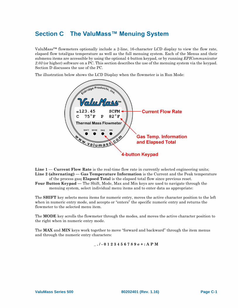
The illustration below shows the LCD Display when the flowmeter is in Run Mode:
Line 1 — Current Flow Rate is the real-time flow rate in currently selected engineering units;
Line 2 (alternating) — Gas Temperature Information is the Current and the Peak temperature
of the process gas; Elapsed Total is the elapsed total flow since previous reset.
Four Button Keypad — The Shift, Mode, Max and Min keys are used to navigate through the
menuing system, select individual menu items and to enter data as appropriate:
The SHIFT key selects menu items for numeric entry, moves the active character position to the left
when in numeric entry mode, and accepts or “enters” the specific numeric entry and returns the
flowmeter to the selected menu item.
The MODE key scrolls the flowmeter through the modes, and moves the active character position to
the right when in numeric entry mode.
The MAX and MIN keys work together to move “forward and backward” through the item menus
and through the numeric entry characters:
_ . / - 0 1 2 3 4 5 6 7 8 9 e + : A P M
Instruction Manual ValuMass™ Flowmeters
Page C-2 80202401 (Rev. 1.16) ValuMass Series 500
The flowmeter must be unlocked to make changes to the variable settings. The factory
default value for menu item 207–UnLock is “9001”. If the numeric entry mode is accessed
while the flowmeter settings are still locked, the top line of the LCD display
will show “**METER LOCKED**” until you press the SHIFT key to exit the numeric
entry mode. When the settings are unlocked, a caret (>) will appear in the upper right
corner of the display.
The following pages explain the LCD displays and the presentation of flow information. Some menu
item headings may be truncated in the display due to the 16-character per line limitation.
100 *Units* Menu
The 100 *Units* Menu of the ValuMass™ flowmeter includes a series of submenu items which allow
you to easily change the engineering units for the flow rate and elapsed total. With the meter settings
unlocked, select the desired engineering units by advancing to the correct menu item and then pressing
SHIFT. The flowmeter will restart using new operational engineering units. The Full Scale and
Maximum Range values are recalculated as part of this process (see menu items 212–FScale and 814–
MaxRange).
The flowmeter settings must be unlocked to change the engineering units, 4-20mA
scaling or to reset the various stored values (see menu item 207–UnLock). The
conversion of engineering units is “1:1” — the flowmeter does not make adjustments for
differences in Reference Conditions between English (Imperial) and metric units, nor
does it adjust for volume to weight conversions for gases other than Air or Nitrogen.
Consult the factory for help with the additional adjustments required for these
situations.
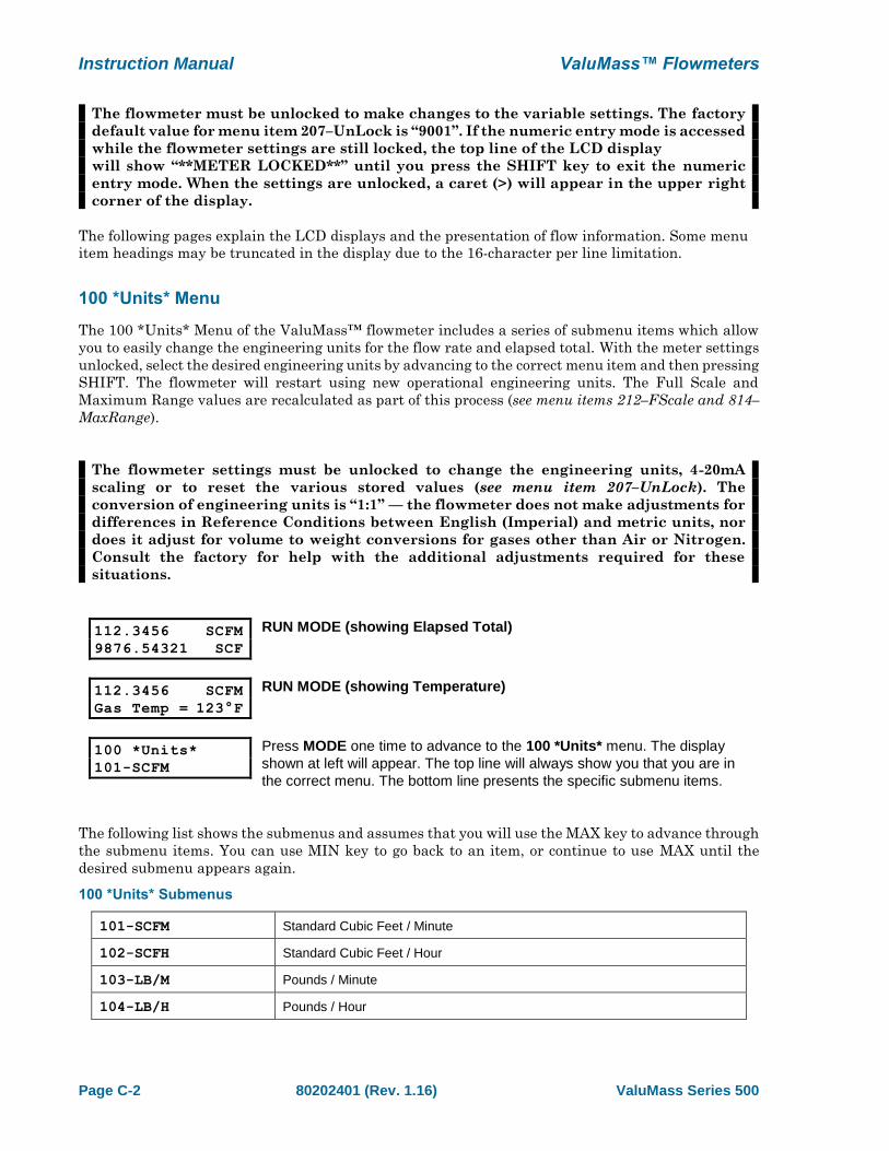
112.3456 SCFM
9876.54321 SCF
RUN MODE (showing Elapsed Total)
112.3456 SCFM
Gas Temp = 123°F
RUN MODE (showing Temperature)
100 *Units*
101-SCFM
Press MODE one time to advance to the 100 *Units* menu. The display
shown at left will appear. The top line will always show you that you are in
the correct menu. The bottom line presents the specific submenu items.
The following list shows the submenus and assumes that you will use the MAX key to advance through
the submenu items. You can use MIN key to go back to an item, or continue to use MAX until the
desired submenu appears again.
100 *Units* Submenus
101-SCFM Standard Cubic Feet / Minute
102-SCFH Standard Cubic Feet / Hour
103-LB/M Pounds / Minute
104-LB/H Pounds / Hour

ValuMass™ Flowmeters Instruction Manual
ValuMass Series 500 80202401 (Rev. 1.16) Page C-3
105-SCIM Standard Cubic Inches / Minute
106-SCIH Standard Cubic Inches / Hour
107- (unused)
108-LB/D Pounds / Day
109-SFPM Standard Feet / Minute
110-SFPS Standard Feet / Second
111-BTUH British Thermal Units / Hour
112-BTUD British Thermal Units / Day
113- (unused)
114- (unused)
115- (unused)
116- (unused)
117-SLPM Standard Liters / Minute
118-SCCM Standard Cubic Centimeters / Minute
119-NCMH Normal Cubic Meters / Hour
120-NCMM Normal Cubic Meters / Minute
121-KG/M Kilograms / Minute
122-KG/H Kilograms / Hour
123-KG/S Kilograms / Second
124-SLPH Standard Liters / Hour
125-NMPS Normal Meters / Second
126-NMPM Normal Meters / Minute
127-NMPH Normal Meters / Hour
128-SCMH Standard Cubic Meters / Hour
129-NLPM Normal Liters / Minute
130-NCCM Normal Cubic Centimeters / Minute
131-NLPH Normal Liters / Hour
(blank)
(blank)
(blank)
(blank)
200 *Utility* Go to 200 *Utility* Menu
300 *Status* Go to 300 *Status* Menu
400 *Alarms* Go to 400 *Alarms* Menu
500 *Run Mode* Go to 500 *Run Mode*

Instruction Manual ValuMass™ Flowmeters
Page C-4 80202401 (Rev. 1.16) ValuMass Series 500
800 *Curve Fit* Go to 200 *Curve Fit* Menu
100 *Units* Go to 100 *Units* Menu
200 *Utility* Menu
The 200 *Utility* Menu of the ValuMass™ flowmeter includes a series of submenu items which allow
you to easily change a wide variety of microprocessor parameters, such as the display update rate, the
internal date and time, etc. Values for timing functions are in millisecond (ms) increments.
Although most settings are accessible by using the default user password of “9001”,
some of the parameters require a special password available only by contacting the
factory. This has been instituted to prevent the accidental change of critical settings.
12.3456 SCFM
9876.54321 SCF
RUN MODE
200 *Utility*
201-LCD Update R
Disp Updt Rate
>2
Press MODE two times to advance to the 200 *Utility* menu. The
display shown at left will appear. The top line will show you that you
are in the correct menu. The bottom line presents the specific
submenu items.
When you select a submenu which supports data entry a brief
description of the selected action will appear on the top line and the
data entry field will appear on the bottom line. In the example at left,
submenu 201-LCD Update Rate has been selected and the flowmeter
is displaying the active stored value.
The following list shows the submenus and assumes that you will use the MAX key to advance through
the submenu items. You can use MIN key to go back to an item, or continue to use MAX until the
desired submenu appears again.
200 *Utility* Submenus
201-LCD Update R This menu item adjusts the rate at which the rate and totalizer readouts are
updated. It is often used to reduce the effect of a rapidly fluctuating flow rate
on the LCD display. Acceptable values are between 8 (ms) and 255 (ms).
This menu item only affects the totalizer and flow rate update period, not their
accuracy, and does not affect the 0–5/10 VDC or 4–20 mA output signals.
202-DAC Update R This menu item is used to adjust the Digital-to-Analog converter (DAC)
response time interval. The value entered here is multiplied by 50ms to
establish the rate at which the DAC generates new output voltages.
Acceptable values are 1 – 63.
203-DAC Filter This menu item provides a smoothed DAC response to compensate for erratic
input signals caused by flow fluctuations. Higher values result in greater
dampening or smoothing; lower values result in a rapid response to changing
signals from the internal curve linearizer. Acceptable values are 1 – 127.

ValuMass™ Flowmeters Instruction Manual
ValuMass Series 500 80202401 (Rev. 1.16) Page C-5
204-Set Date This menu item sets the time stamp functions to the current date for
accurate reporting. The menu supports both MM/DD/YY and
DD.MM.YY time formats where:
• MM = month (01–12)
• DD = day (01–31)
• YY = year (00–99)
Include a slash (/) as the delimiter between values for MM/DD/YY
format, or a period (.) as the delimiter between values for DD.MM.YY
format. The date will not be set if these formats are not followed
exactly.
205-Set Time This menu item sets the time stamp functions to the current time for accurate
reporting. The time prompt indicates HH:MM:SS where:
• HH = hour (00–23)
• MM = minutes (00–59)
• SS = seconds (00–59)
• . (period) = AM /PM or 24 hour clock
Include a colon (:) as the delimiter between values. The time will not be set if
this format is not followed exactly. Example:
01:24:56P = 1:24:56 PM
13:24:56 = 1:24:56 PM displayed in 24 hour clock format.
206-SetCalDate This menu item can be set to act as a reminder for periodic recalibrations. Enter
the date of the next calibration reminder using the MM/DD/YY format, or enter a
zero-zero (00) for either the month or day to disable the reminder.
207-UnLock This menu item is used to enter the pre-set four digit password that unlocks the
flowmeter’s settings. You can access any number of menu items while the
settings are unlocked. The settings are locked again when the flowmeter is
returned to Run Mode.
208-Reset Lock# This menu allows the four digit numeric password to be changed. The
flowmeter must be unlocked prior to accessing this menu item. All flowmeters
are shipped with an initial password of 9001 unless otherwise specified at the
time of purchase. The range of valid passwords is 9001–9999
209-ProtocolOnOf This menu item allows the flowmeter to use alternate communication protocols
such as HART and Modbus. The factory default is Protocol Off (0); when
HART, Modbus or other communication options are installed, the Protocol is
On (1). Consult factory for supported protocols.
210-Vout 0-5,10 This menu item is used to set the voltage output to either 0 – 5 VDC or 0 – 10
VDC (See Menu 211). 0 = 0 – 5 VDC; 1 = 0 – 10 VDC
211-Config Outpu This menu item is used to set the 4 – 20 mA and 0– 5/10 VDC output signal
configurations as shown below:
0 = Flow 4 – 20 mA / Flow 0 – 5/10 VDC
1 = Flow 4 – 20 mA / Temp 0 – 5/10 VDC
2 = Temp 4 – 20 mA / Flow 0 – 5/10 VDC
3 = Temp 4 – 20 mA / Temp 0 – 5/10 VDC
212-Full Scale This menu item is used to adjust the scaling of the 0 – 5/10 VDC and 4 – 20
mA output signals.

Instruction Manual ValuMass™ Flowmeters
Page C-6 80202401 (Rev. 1.16) ValuMass Series 500
213-LCD Update R This menu item adjusts the rate at which the rate and totalizer readouts are
updated. It is often used to reduce the effect of a rapidly fluctuating flow rate
on the LCD display. Acceptable values are between 8 (ms) and 255 (ms).
This menu item only affects the totalizer and flow rate update period, not their
accuracy, and does not affect the 0–5/10 VDC or 4–20 mA output signals.
214-Reset Total This menu item is used to reset the elapsed total, Hi and Lo flow values and
timestamps.
215-FactoryRese This menu item is used to reset the flowmeter to the Factory defaults.
216-Freq Polarit This menu item is used to set the Frequency Output polarity (refer to the
Sink/Source table on page A-4):
0 = LOW @ No Flow with Low to High pulse at flow;
1 = HIGH @ No Flow with High to Low pulse at flow.
Factory Default = 0
217-Pulse Width This menu item is used to set the pulse width of the Frequency Output in 50µs
(50 microseconds) increments between 50µs and 950µs. Non-standard values
are rounded to the nearest 50µs increment.
Factory Default = 500µs
218-Modbus Addr This menu item sets the Modbus address for this flowmeter. A value of 0
disables Modbus protocol from the RS485 communications port and the data
sent out the RS485 port is the same as the RS232 port. A value of 1-127
enables the Modbus protocol on the RS485 port and this number is also the
flowmeter’s Modbus address. See Modbus manual for more details.
220-Diag PSWD This menu item is the factory password for certain menu items that should not
ordinarily be accessed by users. These menu items include:
801-812–CoeffTerm A-J (Curve coefficients) 814–MaxRange
226-SetRS485Baud This menu item adjusts the baud rate of the RS485 port.
0 = Factory Default (19200)
1 = 9600
2 = 14400
3 = 19200
4 = 28800
5 = 33400
6 = 56000
7 = 57600
8 = 115200
RS485 communications require an RS485-to-RS232 protocol converter for
connecting the flowmeter to a PC running EPICommunicator or similar software.
229-NoLCDDisp This menu item controls the microprocessor signal to the LCD: 0 = On, 1 = Off.
230-Temp Zero This menu item sets the temperature value (°F) for the 0 VDC output.
This value is always entered in °F. The temperature displayed will match the
engineering units selected for the flow rate, either Imperial (English) or Metric.
The factory default is 0°F. This setting does NOT affect the temperature
compensation range for the process gas.
231-Temp Span This menu item sets the temperature value (°F) for the 5 VDC output.
This value is always entered in °F. The temperature displayed will match the
engineering units selected for the flow rate, either Imperial (English) or Metric.
The factory default is 250°F. This setting does NOT affect the temperature
compensation range for the process gas.

ValuMass™ Flowmeters Instruction Manual
ValuMass Series 500 80202401 (Rev. 1.16) Page C-7
232-No Disp Temp This menu item controls the temperature display: 0 = On, 1 = Off.
233-RS485 Parity This menu item is used with Modbus communications.
Refer to the EPI Modbus Manual
234-Control Zero This menu item ?????.
235-Bench Zero This menu item ?????.
236-Restore Fact This menu item restores the factory settings.
237-SetPSWDMode This menu item ?????.
299-Cust PSWD This menu allows the four digit numeric password to be changed. The
flowmeter must be unlocked prior to accessing this menu item. All flowmeters
are shipped with an initial password of 9001 unless otherwise specified at the
time of purchase. The range of valid passwords is 9001–9999.
If you set your own password, save it in a secure place to prevent loss and
lockout from user variables.
(blank)
100 *Units* Go to 100 *Meter* Menu
300 *Status* Go to 300 *Status* Menu
400 *Alarms* Go to 400 *Alarms* Menu
500 *Run Mode* Go to 500 *Run Mode*
800 *Curve Fit* Go to 800 *Curve Fit* Menu
300 *Status* Menu
The 300 *Status* Menu of the ValuMass™ flowmeter presents a series of menu items which allow you
to rapidly get important information from the flowmeter.
The following directions assume your flowmeter is in Run Mode and will use the MAX key to advance
through the menu items. You can use MIN key to go back to an item, or continue to use the MAX key
until the desired item appears again.
12.3456 SCFM
9876.54321 SCF
RUN MODE
300 *Status*
100 *Meter*
300 *Status*
1 PO SCFM
Press MODE three times to advance to the 300 *Status* menu. The display
shown at the right will appear briefly. The top line will always show you that
you are in the 300 *Status* menu. The second line presents the specific
menu items.
The display will change automatically to the first Status menu item. The first
character indicates the meter range, the second and third characters
indicate the curve fit mode, and the final characters indicate the currently
selected engineering units for the rate and total information.
Instruction Manual ValuMass™ Flowmeters
Page C-8 80202401 (Rev. 1.16) ValuMass Series 500
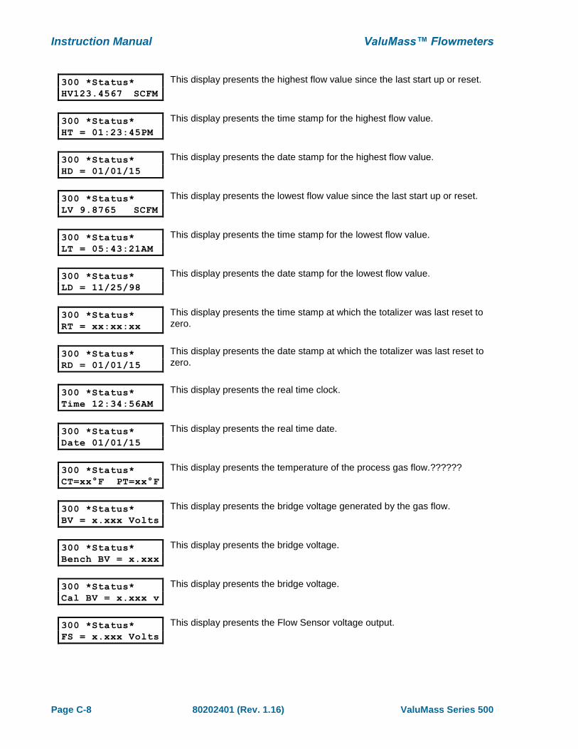
300 *Status*
HV123.4567 SCFM
This display presents the highest flow value since the last start up or reset.
300 *Status*
HT = 01:23:45PM
This display presents the time stamp for the highest flow value.
300 *Status*
HD = 01/01/15
This display presents the date stamp for the highest flow value.
300 *Status*
LV 9.8765 SCFM
This display presents the lowest flow value since the last start up or reset.
300 *Status*
LT = 05:43:21AM
This display presents the time stamp for the lowest flow value.
300 *Status*
LD = 11/25/98
This display presents the date stamp for the lowest flow value.
300 *Status*
RT = xx:xx:xx
This display presents the time stamp at which the totalizer was last reset to
zero.
300 *Status*
RD = 01/01/15
This display presents the date stamp at which the totalizer was last reset to
zero.
300 *Status*
Time 12:34:56AM
This display presents the real time clock.
300 *Status*
Date 01/01/15
This display presents the real time date.
300 *Status*
CT=xx°F PT=xx°F
This display presents the temperature of the process gas flow.??????
300 *Status*
BV = x.xxx Volts
This display presents the bridge voltage generated by the gas flow.
300 *Status*
Bench BV = x.xxx
This display presents the bridge voltage.
300 *Status*
Cal BV = x.xxx v
This display presents the bridge voltage.
300 *Status*
FS = x.xxx Volts
This display presents the Flow Sensor voltage output.
ValuMass™ Flowmeters Instruction Manual
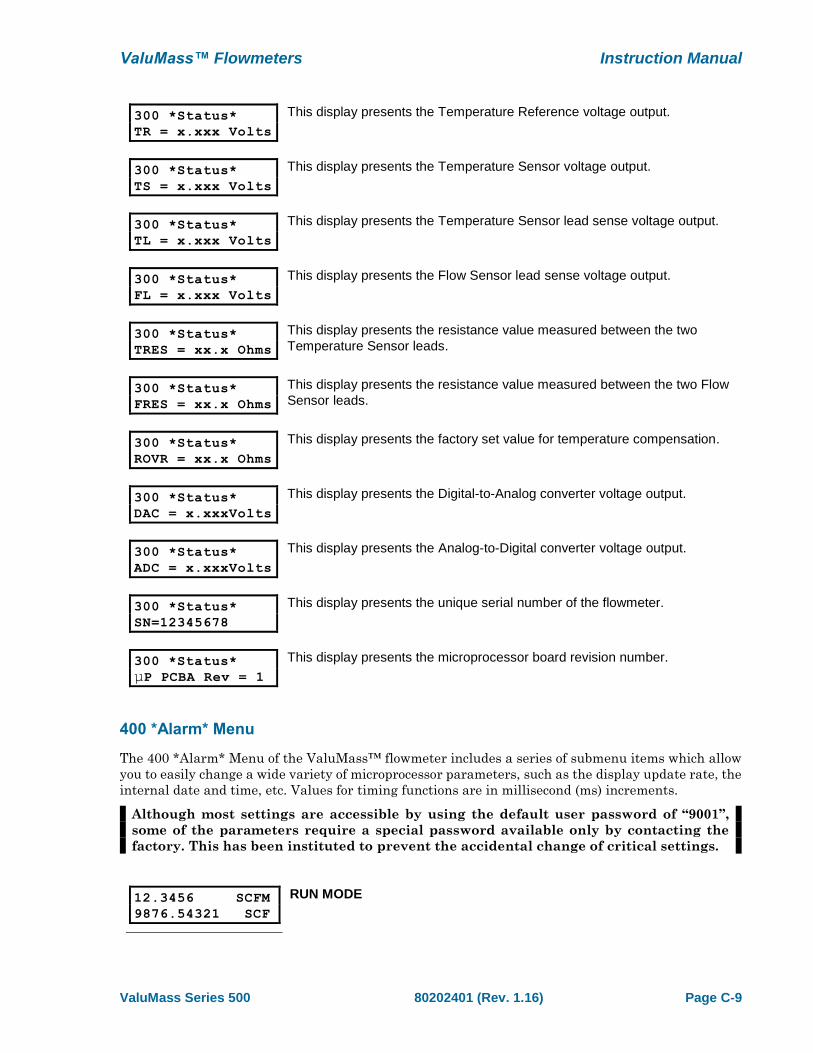
ValuMass Series 500 80202401 (Rev. 1.16) Page C-9
300 *Status*
TR = x.xxx Volts
This display presents the Temperature Reference voltage output.
300 *Status*
TS = x.xxx Volts
This display presents the Temperature Sensor voltage output.
300 *Status*
TL = x.xxx Volts
This display presents the Temperature Sensor lead sense voltage output.
300 *Status*
FL = x.xxx Volts
This display presents the Flow Sensor lead sense voltage output.
300 *Status*
TRES = xx.x Ohms
This display presents the resistance value measured between the two
Temperature Sensor leads.
300 *Status*
FRES = xx.x Ohms
This display presents the resistance value measured between the two Flow
Sensor leads.
300 *Status*
ROVR = xx.x Ohms
This display presents the factory set value for temperature compensation.
300 *Status*
DAC = x.xxxVolts
This display presents the Digital-to-Analog converter voltage output.
300 *Status*
ADC = x.xxxVolts
This display presents the Analog-to-Digital converter voltage output.
300 *Status*
SN=12345678
This display presents the unique serial number of the flowmeter.
300 *Status*
µP PCBA Rev = 1
This display presents the microprocessor board revision number.
400 *Alarm* Menu
The 400 *Alarm* Menu of the ValuMass™ flowmeter includes a series of submenu items which allow
you to easily change a wide variety of microprocessor parameters, such as the display update rate, the
internal date and time, etc. Values for timing functions are in millisecond (ms) increments.
Although most settings are accessible by using the default user password of “9001”,
some of the parameters require a special password available only by contacting the
factory. This has been instituted to prevent the accidental change of critical settings.
12.3456 SCFM
9876.54321 SCF
RUN MODE
Instruction Manual ValuMass™ Flowmeters
Page C-10 80202401 (Rev. 1.16) ValuMass Series 500
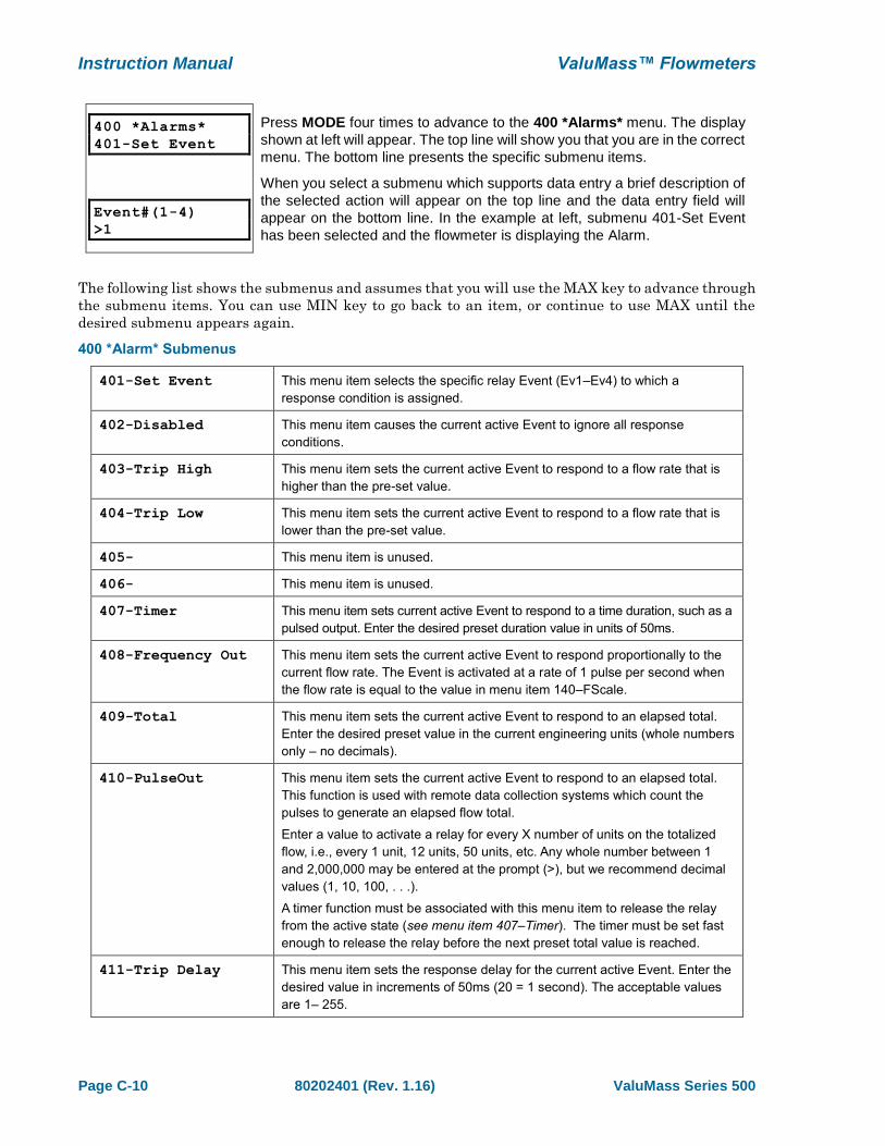
400 *Alarms*
401-Set Event
Event#(1-4)
>1
Press MODE four times to advance to the 400 *Alarms* menu. The display
shown at left will appear. The top line will show you that you are in the correct
menu. The bottom line presents the specific submenu items.
When you select a submenu which supports data entry a brief description of
the selected action will appear on the top line and the data entry field will
appear on the bottom line. In the example at left, submenu 401-Set Event
has been selected and the flowmeter is displaying the Alarm.
The following list shows the submenus and assumes that you will use the MAX key to advance through
the submenu items. You can use MIN key to go back to an item, or continue to use MAX until the
desired submenu appears again.
400 *Alarm* Submenus
401-Set Event This menu item selects the specific relay Event (Ev1–Ev4) to which a
response condition is assigned.
402-Disabled This menu item causes the current active Event to ignore all response
conditions.
403-Trip High This menu item sets the current active Event to respond to a flow rate that is
higher than the pre-set value.
404-Trip Low This menu item sets the current active Event to respond to a flow rate that is
lower than the pre-set value.
405- This menu item is unused.
406- This menu item is unused.
407-Timer This menu item sets current active Event to respond to a time duration, such as a
pulsed output. Enter the desired preset duration value in units of 50ms.
408-Frequency Out This menu item sets the current active Event to respond proportionally to the
current flow rate. The Event is activated at a rate of 1 pulse per second when
the flow rate is equal to the value in menu item 140–FScale.
409-Total This menu item sets the current active Event to respond to an elapsed total.
Enter the desired preset value in the current engineering units (whole numbers
only – no decimals).
410-PulseOut This menu item sets the current active Event to respond to an elapsed total.
This function is used with remote data collection systems which count the
pulses to generate an elapsed flow total.
Enter a value to activate a relay for every X number of units on the totalized
flow, i.e., every 1 unit, 12 units, 50 units, etc. Any whole number between 1
and 2,000,000 may be entered at the prompt (>), but we recommend decimal
values (1, 10, 100, . . .).
A timer function must be associated with this menu item to release the relay
from the active state (see menu item 407–Timer). The timer must be set fast
enough to release the relay before the next preset total value is reached.
411-Trip Delay This menu item sets the response delay for the current active Event. Enter the
desired value in increments of 50ms (20 = 1 second). The acceptable values
are 1– 255.
ValuMass™ Flowmeters Instruction Manual
ValuMass Series 500 80202401 (Rev. 1.16) Page C-11
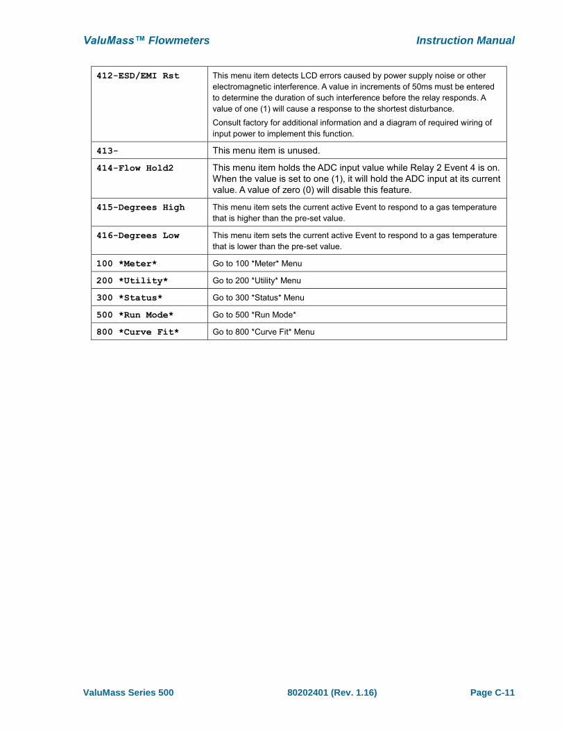
412-ESD/EMI Rst This menu item detects LCD errors caused by power supply noise or other
electromagnetic interference. A value in increments of 50ms must be entered
to determine the duration of such interference before the relay responds. A
value of one (1) will cause a response to the shortest disturbance.
Consult factory for additional information and a diagram of required wiring of
input power to implement this function.
413- This menu item is unused.
414-Flow Hold2 This menu item holds the ADC input value while Relay 2 Event 4 is on.
When the value is set to one (1), it will hold the ADC input at its current
value. A value of zero (0) will disable this feature.
415-Degrees High This menu item sets the current active Event to respond to a gas temperature
that is higher than the pre-set value.
416-Degrees Low This menu item sets the current active Event to respond to a gas temperature
that is lower than the pre-set value.
100 *Meter* Go to 100 *Meter* Menu
200 *Utility* Go to 200 *Utility* Menu
300 *Status* Go to 300 *Status* Menu
500 *Run Mode* Go to 500 *Run Mode*
800 *Curve Fit* Go to 800 *Curve Fit* Menu

Instruction Manual ValuMass™ Flowmeters
Page C-12 80202401 (Rev. 1.16) ValuMass Series 500
800 *Curve Fit* Menu
The ValuMass™ software stores the calibration curve coefficients which are generated by the factory
NIST calibration, as well as the global C-Factor, process line cross-sectional area, etc.
Although most settings are accessible by using the default user password of “9001”,
some of the parameters require a special password available only by contacting the
factory. This has been instituted to prevent the accidental change of critical settings.
The curve coefficients and MaxRange values should never be changed without direct
factory instructions.
12.3456 SCFM
9876.54321 SCF
RUN MODE
800 *Curve Fit*
801-CoeffTerm A
Term A Coeff
>0.000000e+00
Press MODE eight times to advance to the 800 *Curve Fit* menu. The
display shown at left will appear. The top line will show you that you are in
the correct menu. The bottom line presents the specific submenu items.
When you select a submenu which supports data entry a brief description
of the selected action will appear on the top line and the data entry field will
appear on the bottom line. In the example at left, submenu 801-
CoeffTermA has been selected and the flowmeter is displaying the current
coefficient value.
The following list shows the submenus and assumes that you will use the MAX key to advance through
the submenu items. You can use MIN key to go back to an item, or continue to use MAX until the
desired submenu appears again.
800 *Curve Fit* Submenus
801-CoeffTermA Factory Calibration Coefficient.
Requires Diagnostic Password for access. Consult factory.
through
810-CoeffTermJ Factory Calibration Coefficient.
Requires Diagnostic Password for access. Consult factory.
811-C Factor This value is a multiplier used to adjust the Curve linearization. It is normally
set to 1.0, but may be adjusted based the Installation Guidelines, or to correct
for aberrations in sensor readings. The C Factor can also be used to change
standard conditions (STP) or to apply a density factor (vapor density) when
changing the engineering units from volumetric units (SCFM, NCMH, etc.) to
gravimetric units (Lbs/Hr, Kg/Hr, etc.) in flowmeters calibrated for gases other
than air.
812-Zero Offset This voltage value is subtracted from the sensor curve linearizer to correct for
minor sensor voltage errors. This ensures that zero flow is attained even
though some bias voltage may exit which would otherwise prevent an absolute
zero reading (see also menu item 815–Auto Zero).
ValuMass™ Flowmeters Instruction Manual
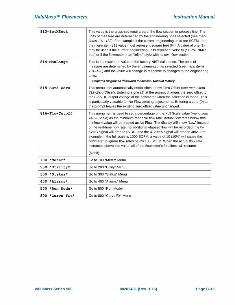
ValuMass Series 500 80202401 (Rev. 1.16) Page C-13
813-SetXSect This value is the cross-sectional area of the flow section or process line. The
units of measure are determined by the engineering units selected (see menu
items 101–132). For example, if the current engineering units are SCFM, then
the menu item 813 value must represent square feet (F2). A value of one (1)
may be used if the current engineering units represent velocity (SFPM, NMPS,
etc.) or if the flowmeter in an “inline” style with its own flow section.
814-MaxRange This is the maximum value of the factory NIST calibration. The units of
measure are determined by the engineering units selected (see menu items
101–132) and the value will change in response to changes to the engineering
units.
Requires Diagnostic Password for access. Consult factory.
815-Auto Zero This menu item automatically establishes a new Zero Offset (see menu item
812–Zero Offset). Entering a one (1) at the prompt changes the zero offset to
the 0–5VDC output voltage of the flowmeter when the selection is made. This
is particularly valuable for No Flow zeroing adjustments. Entering a zero (0) at
the prompt leaves the existing zero offset value unchanged.
816-FlowCutoff This menu item is used to set a percentage of the Full Scale value (menu item
140–FScale) as the minimum readable flow rate. Actual flow rates below this
minimum value will be treated as No Flow. The display will show “Low” instead
of the real-time flow rate, no additional elapsed flow will be recorded, the 0–
5VDC signal will drop to 0VDC, and the 4–20mA signal will drop to 4mA. For
example, if the full scale is 1000 SCFM, a value of 10 (10%) will cause the
flowmeter to ignore flow rates below 100 SCFM. When the actual flow rate
increases above this value, all of the flowmeter’s functions will resume.
(blank)
100 *Meter* Go to 100 *Meter* Menu
200 *Utility* Go to 200 *Utility* Menu
300 *Status* Go to 300 *Status* Menu
400 *Alarms* Go to 400 *Alarms* Menu
500 *Run Mode* Go to 500 *Run Mode*
800 *Curve Fit* Go to 800 *Curve Fit* Menu


ValuMass Series 500 80202401 (Rev. 1.16) Page D-1
Section D The ValuMass™ Menuing System (EPICommunicator™ software)
The following section describes the use of EPICommunicator™ software running on a PC to
communicate with your ValuMass™ flowmeter’s menuing system. For descriptions of the specific
functions, please refer to Section C.
EPICommunicator™ v2.xx
EPICommunicator™ (EPICom) v2.16 (or higher) is proprietary software for use with Master-Touch™
and ValuMass™ flowmeters. EPICom uses the RS232 communication protocol to connect a
ValuMass™ flowmeter directly to a PC running Windows XP®. The software is available to download
is .zip format at no charge from our web site, www.valumass.com.
Please note that older versions of the software do NOT support this version of
ValuMass™ menuing system.
Connecting Your PC to Your ValuMass™ Flow Meter
Use the connection terminals on the ValuMass™ flowmeter to connect the flowmeter to the correct
COM port on your PC. EPICom is pre-configured so that no configuration adjustments should be
necessary. Alternately, you may also use line-of-sight infrared communications if you have purchased
the required EPI LightWIRE™ module(s). Contact the factory or your local sales representative for
more information concerning LightWIRE™ products.
Installing and Starting EPICom
The EPICommunicator .zip file (EPICom V2.x.zip) contains the basic files required for the proper
operation of the software. To install EPICom, first create a folder into which the .zip file will be
extracted. The name of this folder is not critical to the installation process. Extract all of the files to
the folder. No other installation steps — such as the typical Windows™ installation wizard — are
required.
These files are all essential to the proper operation of EPICom software. They must all
be stored in the same folder. Do not modify them in any way.
Upon request, you may also receive the data files for your specific ValuMass™ flowmeters directly
from EPI. The naming convention for these files is “XXXXXXXX_1.vmm.” The first eight digits are the
flowmeter’s serial number.
To start EPICom, open the EPICom folder and double-click on EPICom V2.x.exe file or its icon.
EPICom will open to a blank screen with the menu bar shown below:
To open the EPITerm module, click on . To open the ValuMass™ module, click
Instruction Manual ValuMass™ Flowmeters
Page D-2 80202401 (Rev. 1.16) ValuMass Series 500
To communicate with your ValuMass™ flowmeter, begin by opening the EPITerm module.
Successfully connecting to the flowmeter with EPITerm should assure that any subsequent connection
to the VM500 module would also be successful. If you experience any problems in establishing the
connection with EPITerm, first check the connection and to the COM port selection. EPI technicians
use EPICommunicator as part of the set up process for all ValuMass™ flowmeters, and they verify
that the communications are working correctly as part of the final testing process at our facility.
However, if problems with the connection continue on site, please contact the factory.
The ValuMass™ flowmeter does NOT work with the MT8000 (Master-Touch™) or E-LOG
(E-Logger™) modules. They are intended for use with EPI’s Master-Touch™ flowmeters.
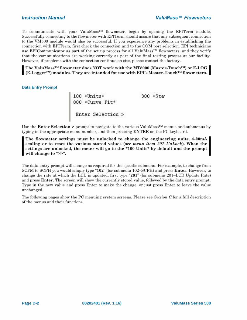
Data Entry Prompt
Use the Enter Selection > prompt to navigate to the various ValuMass™ menus and submenus by
typing in the appropriate menu number, and then pressing ENTER on the PC keyboard.
The flowmeter settings must be unlocked to change the engineering units, 4-20mA
scaling or to reset the various stored values (see menu item 207–UnLock). When the
settings are unlocked, the meter will go to the *100 Units* by default and the prompt
will change to “>>”.
The data entry prompt will change as required for the specific submenu. For example, to change from
SCFM to SCFH you would simply type “102” (for submenu 102–SCFH) and press Enter. However, to
change the rate at which the LCD is updated, first type “201” (for submenu 201–LCD Update Rate)
and press Enter. The screen will show the currently stored value, followed by the data entry prompt.
Type in the new value and press Enter to make the change, or just press Enter to leave the value
unchanged.
The following pages show the PC menuing system screens. Please see Section C for a full description
of the menus and their functions.
ValuMass™ Flowmeters Instruction Manual
ValuMass Series 500 80202401 (Rev. 1.16) Page D-3
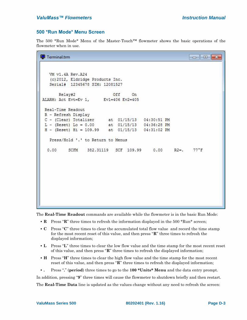
500 *Run Mode* Menu Screen
The 500 *Run Mode* Menu of the Master-Touch™ flowmeter shows the basic operations of the
flowmeter when in use.
The Real-Time Readout commands are available while the flowmeter is in the basic Run Mode:
• R Press “R” three times to refresh the information displayed in the 500 *Run* screen;
• C Press “C” three times to clear the accumulated total flow value and record the time stamp
for the most recent reset of this value, and then press “R” three times to refresh the
displayed information;
• L Press “L” three times to clear the low flow value and the time stamp for the most recent reset
of this value, and then press “R” three times to refresh the displayed information;
• H Press “H” three times to clear the high flow value and the time stamp for the most recent
reset of this value, and then press “R” three times to refresh the displayed information;
• . Press “.” (period) three times to go to the 100 *Units* Menu and the data entry prompt.
In addition, pressing “9” three times will cause the flowmeter to shutdown briefly and then restart.
The Real-Time Data line is updated as the values change without any need to refresh the screen:
Instruction Manual ValuMass™ Flowmeters
Page D-4 80202401 (Rev. 1.16) ValuMass Series 500
• Rate The current flow rate in current engineering units;
• Total The accumulated flow total since the last Total reset;
• High The highest flow rate since the last High reset;
• Low The lowest flow rate since the last Low reset;
• Temp The current gas temperature (Fahrenheit or Celsius dependent upon the selected
engineering units)

ValuMass™ Flowmeters Instruction Manual
ValuMass Series 500 80202401 (Rev. 1.16) Page D-5
100 *Units* Menu Screen
The 100 *Units* Menu of the ValuMass™ flowmeter includes a series of submenu items which allow
you to easily change the engineering units for the flow rate and elapsed total.
With the meter settings unlocked, type the menu number of desired engineering unit at the prompt
and then press ENTER. The flowmeter will restart using new operational engineering units. The Full
Scale and Maximum Range values are recalculated as part of this process (see menu items 212–FScale
and 814–MaxRange).
The flowmeter settings must be unlocked to change the engineering units, 4-20mA
scaling or to reset the various stored values (see menu item 207–UnLock). The
conversion of engineering units is “1:1” — the flowmeter does not make adjustments for
differences in Reference Conditions between English (Imperial) and metric units, nor
does it adjust for volume to weight conversions for gases other than Air or Nitrogen.
Consult the factory for help with the additional adjustments required for these
situations.
Instruction Manual ValuMass™ Flowmeters
Page D-6 80202401 (Rev. 1.16) ValuMass Series 500
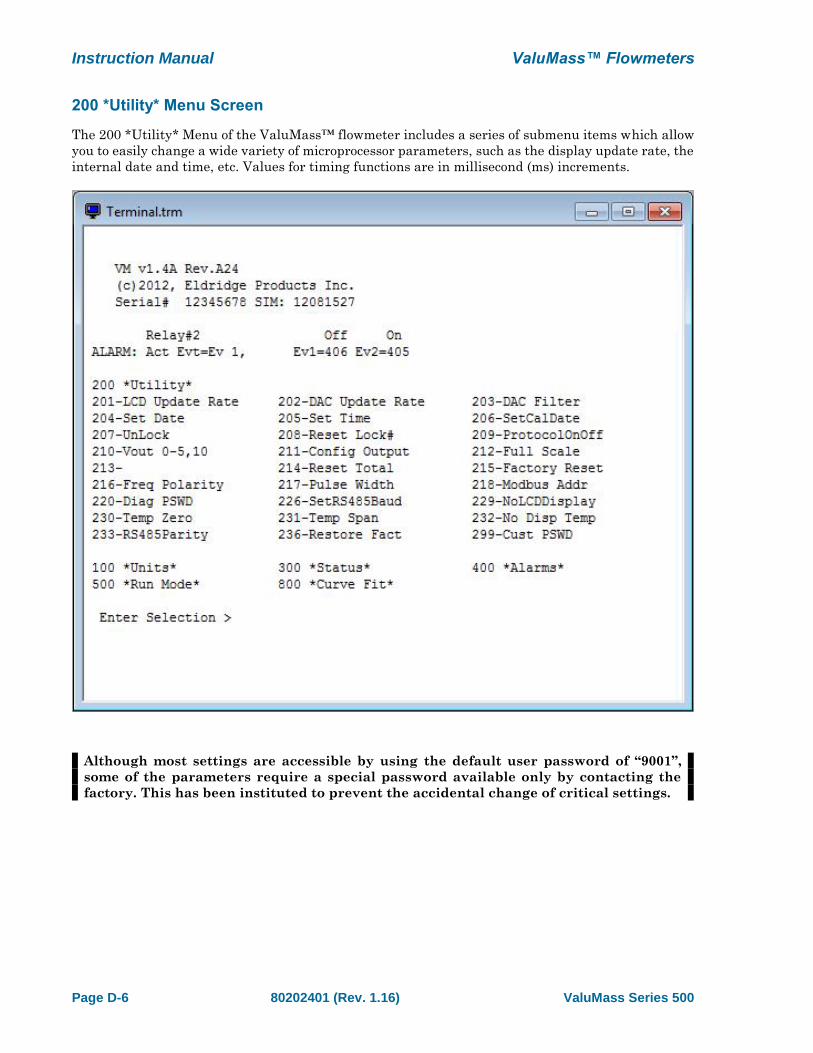
200 *Utility* Menu Screen
The 200 *Utility* Menu of the ValuMass™ flowmeter includes a series of submenu items which allow
you to easily change a wide variety of microprocessor parameters, such as the display update rate, the
internal date and time, etc. Values for timing functions are in millisecond (ms) increments.
Although most settings are accessible by using the default user password of “9001”,
some of the parameters require a special password available only by contacting the
factory. This has been instituted to prevent the accidental change of critical settings.

ValuMass™ Flowmeters Instruction Manual
ValuMass Series 500 80202401 (Rev. 1.16) Page D-7
300 *Status* Menu Screen
The 300 *Status* Menu is intended for use with the LCD display and does not present
information on the PC screen.
Instruction Manual ValuMass™ Flowmeters
Page D-8 80202401 (Rev. 1.16) ValuMass Series 500
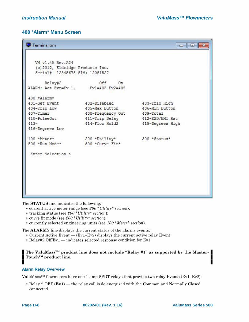
400 *Alarm* Menu Screen
The STATUS line indicates the following:
• current active meter range (see 200 *Utility* section);
• tracking status (see 200 *Utility* section);
• curve fit mode (see 200 *Utility* section);
• currently selected engineering units (see 100 *Meter* section).
The ALARMS line displays the current status of the alarms events:
• Current Active Event — (Ev1–Ev2) displays the current active relay Event
• Relay#2 Off/Ev1 — indicates selected response condition for Ev1
The ValuMass™ product line does not include “Relay #1” as supported by the Master-
Touch™ product line.
Alarm Relay Overview
ValuMass™ flowmeters have one 1-amp SPDT relays that provide two relay Events (Ev1–Ev2):
• Relay 2 OFF (Ev1) — the relay coil is de-energized with the Common and Normally Closed
connected
ValuMass™ Flowmeters Instruction Manual
ValuMass Series 500 80202401 (Rev. 1.16) Page D-9
• Relay 2 ON (Ev2) — the relay coil is energized with the Common and Normally Open
connected
The ValuMass™ product line does not include “Relay 1” as supported by the Master-
Touch™ product line.
These events can be used to activate other devices in response to user-defined flow conditions, or to
provide a pulsed output based on an elapsed flow total. There are thirteen user-selectable conditions
which will trigger an alarm relay response from a Master-Touch flowmeter. These conditions are:
• Trip High — an alarm relay is triggered by a flow rate that is higher than the preset value;
• Trip Low — an alarm relay is triggered by a flow rate that is lower than the preset value;
• Total — an alarm relay is triggered by an accumulated flow total that is higher than the preset
value;
• Timer — an alarm relay is triggered after a preset time delay value;
• Frequency Output — an alarm relay is triggered by a flow rate that is equal to a preset
proportion of the value in menu item 140–FScale;
• Pulse Output — an alarm relay is triggered after an preset value of accumulated flow total;
• ESD/EMI Rst — an alarm relay is triggered by electromagnetic impulse noise.
• Flow Hold 2 — the ADC input voltage is maintained at constant value, typically during gas
purge cycle
• Temp High — an alarm relay is triggered by a process gas temperature that is higher than the
preset value;
• Temp Low — an alarm relay is triggered by a process gas temperature that is lower than the
preset value;
In addition, the alarm relay can be Disabled so it does not trigger on any Event. The Disabled function
is also used to latch or hold the relay at its current condition. If no Event programming has been
requested at the time of purchase, Disabled is the default condition for the alarm relay.
Alarm Programming
The flowmeter settings must be unlocked to change the alarm relay parameters (see
menu item 219–UnLock).
The alarm relay only operates while the flowmeter is the Run Mode. To select and program alarm
relay Events, use the 400 *Alarms* menu items. First, select the specific Event (Ev1–Ev2) in menu
item 401–Set Event. After selecting an Event, a condition is assigned (Timer, Max, Pulse Out, etc.).
With the exception of setting the Disable, each condition requires a numeric value to control the
response. Depending upon the selected condition, these values refer to 50 millisecond (ms) increments
or to the currently selected engineering units.
The flowmeter accepts settings for the Event until it returns to Run Mode, or until another Event is
selected by returning to menu item 401. Therefore, if a mistake is made while setting the parameters
for an Event, such as selecting Trip High instead of Trip Low, there is no need to undo the previous
settings — simply select the correct menu item and continue entering the settings.
The following is an example of the steps required for a typical use of the Master-Touch alarm relays:
Set Alarm Relay 2 to activate for each accumulated flow total of 100 SCF with a 100 millisecond pulse
width:
• Unlock the flowmeter settings and go to the 400 *Alarms* menu;
• Select menu item 401–Set Event, then enter 1 at the prompt (1 = Ev 1, Relay 2 OFF);
• Select menu item 407–Timer, then enter 2 at prompt (2 x 50ms = 100ms);
• Select menu item 401–Set Event, then enter 2 at the prompt (2 = Ev 2, Relay 2 ON);

Instruction Manual ValuMass™ Flowmeters
Page D-10 80202401 (Rev. 1.16) ValuMass Series 500
• Select menu item 410–PulseOut, then enter 100 (SCF) at menu prompt;
• Select menu item 500 *Run Mode* to lock the flowmeter and return to Run Mode.
EPIMeter supports Alarm programming through a series of pull-down menus which
provide the simplest means of setting up complex Alarm parameters.
ValuMass™ Flowmeters Instruction Manual
ValuMass Series 500 80202401 (Rev. 1.16) Page D-11
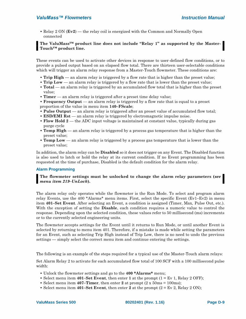
800 *Curve Fit* Menu Screen
The ValuMass™ software stores the calibration curve coefficients which are generated by the factory
NIST calibration, as well as the global C-Factor, process line cross-sectional area, etc.
Although most settings are accessible by using the default user password of “9001”,
some of the parameters require a special password available only by contacting the
factory. This has been instituted to prevent the accidental change of critical settings.
The curve coefficients and MaxRange values should never be changed without direct
factory instructions.
Instruction Manual ValuMass™ Flowmeters
Page D-12 80202401 (Rev. 1.16) ValuMass Series 500
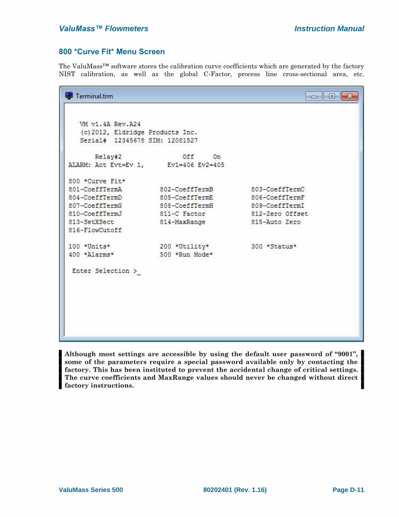
The ValuMass™ Module
The ValuMass™ Module presents most of the flowmeter’s stored settings in one convenient screen
display. You can access the module by clicking on the icon.
The screen shown below will appear, though it will not have data for your flowmeter at first. To
populate the data fields with the settings from your flowmeter, click the “Read” button. You may also
open stored files for review through the “File” menu by selecting “Open” and locating the appropriate
*.vmm file as you would when opening any other file.
The various settings can be adjusted by either entering the new values directly into the data fields,
by selecting from a dropdown list or by using the Up/Down arrows, depending on which values you
are modifying. The values in grey fields cannot be modified by the user and are presented for
reference only. When you have made any required adjustments, click the “Send” button to download
the settings to the flowmeter.
ValuMass™ Flowmeters Instruction Manual
ValuMass Series 500 80202401 (Rev. 1.16) Page D-13
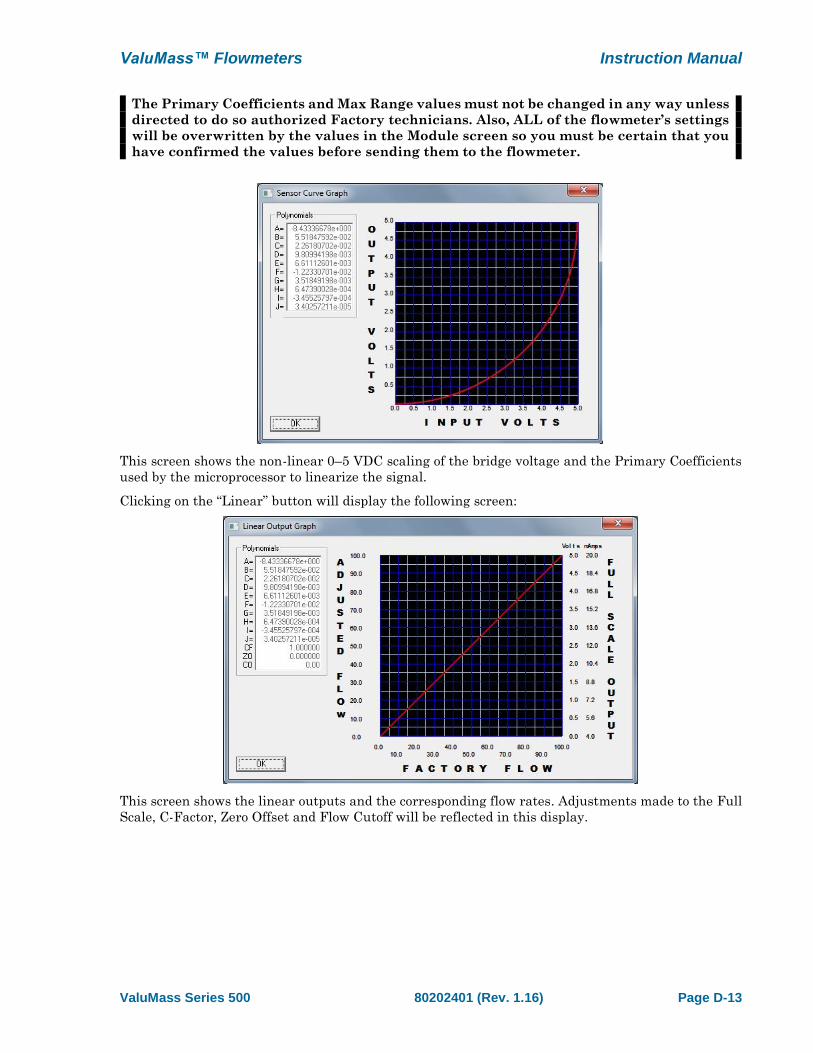
The Primary Coefficients and Max Range values must not be changed in any way unless
directed to do so authorized Factory technicians. Also, ALL of the flowmeter’s settings
will be overwritten by the values in the Module screen so you must be certain that you
have confirmed the values before sending them to the flowmeter.
This screen shows the non-linear 0–5 VDC scaling of the bridge voltage and the Primary Coefficients
used by the microprocessor to linearize the signal.
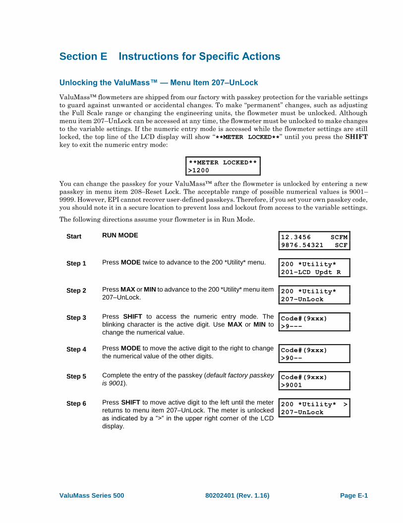
Clicking on the “Linear” button will display the following screen:
This screen shows the linear outputs and the corresponding flow rates. Adjustments made to the Full
Scale, C-Factor, Zero Offset and Flow Cutoff will be reflected in this display.

ValuMass Series 500 80202401 (Rev. 1.16) Page E-1
Section E Instructions for Specific Actions
Unlocking the ValuMass™ — Menu Item 207–UnLock
ValuMass™ flowmeters are shipped from our factory with passkey protection for the variable settings
to guard against unwanted or accidental changes. To make “permanent” changes, such as adjusting
the Full Scale range or changing the engineering units, the flowmeter must be unlocked. Although
menu item 207–UnLock can be accessed at any time, the flowmeter must be unlocked to make changes
to the variable settings. If the numeric entry mode is accessed while the flowmeter settings are still
locked, the top line of the LCD display will show “**METER LOCKED**” until you press the SHIFT
key to exit the numeric entry mode:
**METER LOCKED**
>1200
You can change the passkey for your ValuMass™ after the flowmeter is unlocked by entering a new
passkey in menu item 208–Reset Lock. The acceptable range of possible numerical values is 9001–
9999. However, EPI cannot recover user-defined passkeys. Therefore, if you set your own passkey code,
you should note it in a secure location to prevent loss and lockout from access to the variable settings.
The following directions assume your flowmeter is in Run Mode.
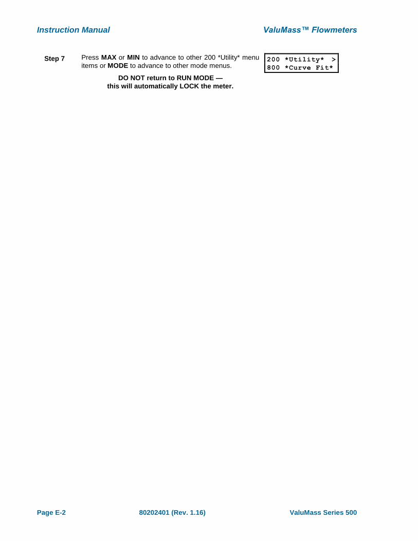
Start RUN MODE 12.3456 SCFM
9876.54321 SCF
Step 1 Press MODE twice to advance to the 200 *Utility* menu. 200 *Utility*
201–LCD Updt R
Step 2 Press MAX or MIN to advance to the 200 *Utility* menu item
207–UnLock. 200 *Utility*
207–UnLock
Step 3 Press SHIFT to access the numeric entry mode. The
blinking character is the active digit. Use MAX or MIN to
change the numerical value.
Code#(9xxx)
>9–––
Step 4 Press MODE to move the active digit to the right to change
the numerical value of the other digits. Code#(9xxx)
>90––
Step 5 Complete the entry of the passkey (default factory passkey
is 9001). Code#(9xxx)
>9001
Step 6 Press SHIFT to move active digit to the left until the meter
returns to menu item 207–UnLock. The meter is unlocked
as indicated by a “>“ in the upper right corner of the LCD
display.
200 *Utility* >
207–UnLock
Instruction Manual ValuMass™ Flowmeters
Page E-2 80202401 (Rev. 1.16) ValuMass Series 500
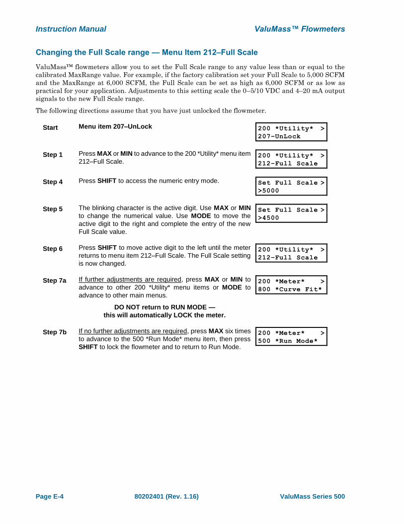
Step 7 Press MAX or MIN to advance to other 200 *Utility* menu
items or MODE to advance to other mode menus.
DO NOT return to RUN MODE —
this will automatically LOCK the meter.
200 *Utility* >
800 *Curve Fit*

ValuMass™ Flowmeters Instruction Manual
ValuMass Series 500 80202401 (Rev. 1.16) Page E-3
Selecting the Engineering Units — Menu Items 101–132
ValuMass™ flowmeters allow you to choose from a variety of engineering units to measure the flow
rate and elapsed total. The menu items 101 through 132 have been designated for this purpose, though
not all items are currently assigned. Please note that changing the engineering units from SCFM,
NCMH, etc. to Lb/H, Kg/H, etc. requires factory assistance for all gases other than air.
The following directions assume that you have just unlocked the flowmeter. However, the 100 *Units*
menu can be accessed directly from the other mode menus by pressing MODE until it is shown on the
LCD display and then pressing SHIFT.
Start Menu item 207–UnLock 200 *Utility* >
207–UnLock
Step 1 Press MAX twice to advance to the 200 *Utility* menu item
100 *Units*. 200 *Utility* >
100 *Units*
Step 2 Press SHIFT to advance to the 100 *Units* menu. 100 *Units* >
101–SCFM
Step 3 Press MAX or MIN to advance to the 100 *Units* menu item
of the engineering unit you desire. Press SHIFT to select
the engineering unit.
100 *Units* >
119–NCMH
NOTE DO NOT select any blank menu item — this will cause
a failure and the flowmeter will need to be powered
down and powered up again.
100 *Units* >
107–
Step 4a If further adjustments are required, press MAX or MIN to
advance to other 100 *Units* menu items or MODE to
advance to other main menus.
DO NOT return to RUN MODE —
this will automatically LOCK the meter.
100 *Units* >
800 *Curve Fit*
Step 4b If no further adjustments are required, press MAX to
advance to the 500 *Run Mode* menu item, then press
SHIFT to lock the flowmeter and to return to Run Mode.
100 *Units* >
500 *Run Mode*
Instruction Manual ValuMass™ Flowmeters
Page E-4 80202401 (Rev. 1.16) ValuMass Series 500
Changing the Full Scale range — Menu Item 212–Full Scale
ValuMass™ flowmeters allow you to set the Full Scale range to any value less than or equal to the
calibrated MaxRange value. For example, if the factory calibration set your Full Scale to 5,000 SCFM
and the MaxRange at 6,000 SCFM, the Full Scale can be set as high as 6,000 SCFM or as low as
practical for your application. Adjustments to this setting scale the 0–5/10 VDC and 4–20 mA output
signals to the new Full Scale range.
The following directions assume that you have just unlocked the flowmeter.
Start Menu item 207–UnLock 200 *Utility* >
207–UnLock
Step 1 Press MAX or MIN to advance to the 200 *Utility* menu item
212–Full Scale. 200 *Utility* >
212–Full Scale
Step 4 Press SHIFT to access the numeric entry mode. Set Full Scale >
>5000
Step 5 The blinking character is the active digit. Use MAX or MIN
to change the numerical value. Use MODE to move the
active digit to the right and complete the entry of the new
Full Scale value.
Set Full Scale >
>4500
Step 6 Press SHIFT to move active digit to the left until the meter
returns to menu item 212–Full Scale. The Full Scale setting
is now changed.
200 *Utility* >
212–Full Scale
Step 7a If further adjustments are required, press MAX or MIN to
advance to other 200 *Utility* menu items or MODE to
advance to other main menus.
DO NOT return to RUN MODE —
this will automatically LOCK the meter.
200 *Meter* >
800 *Curve Fit*
Step 7b If no further adjustments are required, press MAX six times
to advance to the 500 *Run Mode* menu item, then press
SHIFT to lock the flowmeter and to return to Run Mode.
200 *Meter* >
500 *Run Mode*

ValuMass™ Flowmeters Instruction Manual
ValuMass Series 500 80202401 (Rev. 1.16) Page E-5
Resetting the Flow Rate and Flow Total — Menu Item 214–Reset!
ValuMass™ flowmeters allow you to reset the flow rate and elapsed flow totals to zero at any time.
The flowmeter must be unlocked for reset these values.
The following directions assume that you are in Run Mode. However, the 200 *Utility* menu can be
accessed directly from the other mode menus by pressing MODE until it is shown on the LCD display
and then pressing SHIFT.
Start Menu item 207–UnLock 200 *Utility* >
207–UnLock
Step 1 Press MAX or MIN to advance to menu item 214–Reset!.
Press SHIFT to reset the values to zero. The flowmeter will
automatically return to Run Mode within 1–2 seconds.
200 *Utility*
>
214–Reset Total

Instruction Manual ValuMass™ Flowmeters
Page E-6 80202401 (Rev. 1.16) ValuMass Series 500
Adjusting the C Factor — Menu Item 811–C Factor
ValuMass™ flowmeters allow you to adjust the correction factor setting. By changing the value in this
menu item, you can rescale the flowmeter’s curve linearization to correct for aberrations in the sensor
readings.
The following directions assume that you have just unlocked the flowmeter. However, the 800 *Curve
Fit* menu can be accessed directly from the other mode menus by pressing MODE until it is shown on
the LCD display and then pressing SHIFT.
Start Menu item 219–UnLock: 200 *Utility* >
219–UnLock
Step 1 Press MAX five times to advance to the 200 *Utility* menu
item 800 *Factory*. 200 *Utility* >
800 *Curve Fit*
Step 2 Press SHIFT to advance to the 800 *Factory* menu. 800 *Curve Fit*>
801–CoeffTermA
Step 3 Press MAX or MIN to advance to the 800 *Factory* menu
item 811–C Factor. 800 *Curve Fit*>
811–C Factor
Step 4 Press SHIFT to access the numeric entry mode. Set Correction >
>1.000000e+00
Step 5 The blinking character is the active digit. Use MAX or MIN
to change the numerical value. Use MODE to move the
active digit to the right and complete the entry of the new
correction factor.
Set Correction >
>1.050000e+00
Step 6 Press SHIFT to move active digit to the left until the meter
returns to menu item 811–C Factor. The correction factor is
now changed.
800 *Curve Fit*>
811–C Factor
Step 7a If further adjustments are required, press MAX or MIN to
advance to other 800 *Curve Fit* menu items or MODE to
advance to other main menus.
DO NOT return to RUN MODE —
this will automatically LOCK the meter.
800 *Curve Fit*>
801–CoeffTermA
Step 7b If no further adjustments are required, press MODE to
advance to the 500 *Run Mode* menu and press SHIFT.
The flowmeter will return to Run Mode and relock.
800 *Curve Fit*>
500 *Run Mode*

ValuMass™ Flowmeters Instruction Manual
ValuMass Series 500 80202401 (Rev. 1.16) Page E-7
Changing the Cross-Sectional Area — Menu Item 813–SetXSect
Insertion-style ValuMass™ flowmeters allow you to change the cross-sectional area setting. This
allows an insertion flowmeter to be used in more than one size process line. When the cross-sectional
area is changed, the flowmeter automatically recalculates the 140–FScale and 814–MaxRange values
based upon the velocity of factory calibration. Although no units of measurement are included in the
cross-sectional area entry, the flowmeter’s microprocessor assumes compatibility with the selected
engineering units, i.e., a value of “4” is assumed to be 4 square feet if the engineering units are SCFM,
whereas a value of “4” is assumed to be 4 square meters if the engineering units are NCMH.
The following directions assume that you have just unlocked the flowmeter. However, the 800 *Curve
Fit* menu can be accessed directly from the other mode menus by pressing MODE until it is shown on
the LCD display and then pressing SHIFT.
Start Menu item 219–UnLock: 200 *Utility* >
219–UnLock
Step 1 Press MAX five times to advance to the 200 *Utility* menu
item 800 *Factory*. 200 *Utility* >
800 *Factory*
Step 2 Press SHIFT to advance to the 800 *Factory* menu. 800 *Curve Fit*>
801–CoeffTermA
Step 3 Press MAX or MIN to advance to the 800 *Factory* menu
item 813–SetXSect. 800 *Curve Fit*>
813–SetXSect
Step 4 Press SHIFT to access the numeric entry mode. Set X-Sec >
>4.5
Step 5 The blinking character is the active digit. Use MAX or MIN
to change the numerical value. Use MODE to move the
active digit to the right and complete the entry of the new
cross-sectional area.
Set X-Sec >
>3.75
Step 6 Press SHIFT to move active digit to the left until the meter
returns to menu item 813–SetXSect. The cross-sectional
area is now changed.
800 *Curve Fit*>
813–SetXSect
Step 7a If further adjustments are required, press MAX or MIN to
advance to other 800 *Curve Fit* menu items or MODE to
advance to other main menus.
DO NOT return to RUN MODE —
this will automatically LOCK the meter.
800 *Curve Fit*>
801–CoeffTermA
Step 7b If no further adjustments are required, press MODE to
advance to the 500 *Run Mode* menu and press SHIFT.
The flowmeter will return to Run Mode and relock.
800 *Curve Fit*>
500 *Run Mode*

ValuMass Series 500 80202401 (Rev. 1.16) Page F-1
Section F Factory Calibration
The factory calibration of an Eldridge thermal gas mass flowmeter is a two step process. Our first step
is to perform a temperature calibration of each flow sensor. Once this calibration process has been
performed, it need not be done again. Secondly, we perform a flow calibration of every flowmeter.
Although all flow curves are similar, they are different enough to require individual calibrations be
run for each flowmeter to yield the best accuracy.
Flow calibration is a process of comparing or verifying the meter under test against a meter of better
accuracy used as a calibration standard. EPI flow calibrations are traceable to NIST through
traceability of the instrumentation and equipment used.
Calibration of the flowmeter consists of the following steps. Flowmeters are checked against a
calibration standard at many flow points and the data is graphed. From this graph the non-linearity
of the flowmeter is determined and aligned through our signal processor to yield a linear flow output
signal.
Although thermal gas mass flowmeters have good long term stability, EPI recommends a factory
calibration and certification be performed on an annual basis to conform to most quality assurance
programs. Where quality assurance programs do not require annual recertification, it shall be left at
the users’ discretion when to recertify.


ValuMass Series 500 80202401 (Rev. 1.16) Page G-1
Section G General Specifications
Flow Accuracy (including linearity) ± [1% of Reading + (0.5% Full Scale + 0.05% / °C)]
Repeatability ± 0.2% of Full Scale
Temperature Accuracy (NA) Expected ± 2°F (1°C), ± 1°F (0.5°C) optional
Linear Signal Output 0 – 5 or 10 VDC, 4 – 20 mA (Flow and Temperature)
0 – 1 kHz (proportional to Flow)
Sensor Response Time 1 second
Turndown Ratio 100:1 (not less than 15 SCFM / FT2)
Transmitter Operating Temperature 0 – 130°F (-18° – 55°C)
Temperature Compensation Standard 40° – 100°F (4 –38°C)
Optional 0° – 250°F (-18° – 121°C)
Gas Pressure Effect Negligible over 20% of absolute calibration pressure
Pressure Rating Maximum:
Inline Flowmeters 500 PSIG
Insertion Flowmeters 500 PSIG (Stainless Steel ferrule)
25 PSIG (Teflon™ ferrule), 250 PSIG with Locking collar
& safety cable.
Input Power Requirement 24 VDC @ 250 mA
115 VAC 50/60 Hz optional
230 VAC 50/60 Hz optional
Transmitter Power Requirements 5 Watts or less
Relay Output Rating 1 Amp @ 30VDC (33W) (2 Relays,1 if Freq.Out needed)
Communications Port RS-232C
Optional LightWIRE™ infrared
Display Optional 2-lines, 16 characters per line, backlit LCD
with 4-button keypad
Wetted Materials 316 & 316L Stainless Steel
Standard Temperature & Pressure (STP) 70°F & 29.92" Hg
(Air = 0.075 Lbs. / FT3)
NIST Traceable Calibration Standard
Enclosure Rating NEMA 4X (IP66)
Approvals CE Mark
Insertion probe PSI is rated to limit applied force at probe to a maximum of 25 pounds.
Above the listed pressure, a restraining device is required to eliminate the potential of
the probe being forced out of the line during installation or removal under pressure.

Instruction Manual ValuMass™ Flowmeters
Page G-2 80202401 (Rev. 1.16) ValuMass Series 500
Specification Notice
Specifications contained herein are subject to change without notice, EPI cannot guarantee the
applicability or suitability of our products in all situations since it is impossible to anticipate or control
every condition under which our products and specifications may be used.
Service Work
In the event that service work is required or calibration and recertification is required, call the factory
and a return materials authorization (RMA) number will be issued for each job. All units sent in for
service work shall include a RMA, work instructions and be shipped prepaid. On receipt of your flow
instrumentation, we will inspect the equipment and give a price quotation for service work to be
performed, if not already given.
Storage
Equipment and instrumentation shall be stored in an environmentally controlled storage shelter or
warehouse when not in use. All openings shall be sealed off to prevent foreign materials from entering
the instrumentation.
Limited Warranty
Eldridge Products, Inc. (EPI) warrants its products to be free from defects in materials and
workmanship for one year from the date of factory shipment. If there is a defect, the purchaser must
notify EPI of the defect within the warranty period. Upon receipt of the defective product, EPI will
either repair or replace the defective product at its sole option and at no cost to the purchaser. EPI
MAKES NO OTHER WARRANTY, EXPRESS OR IMPLIED, AS TO THE PRODUCTS. EPI MAKES
NO WARRANTY THAT THE GOODS SOLD TO ANY PURCHASER ARE FIT FOR ANY
PARTICULAR PURPOSE. FURTHERMORE, EPI MAKES NO WARRANTY OF
MERCHANTABILITY WITH RESPECT TO ANY PRODUCTS SOLD TO ANY PURCHASERS. There
are no other warranties that extend beyond the description on any brochure or price quote.
Limited Acceptance
Acceptance of any offer is limited to its terms. Acceptances or confirmations that state additional or
differing terms from this price quote shall be operative as acceptances, but all additional or differing
terms shall be deemed material alterations within the meaning of Commercial Code Section
2207(2)(b), and notice of objection to them pursuant to Commercial Code Section 2207(2)(c) is hereby
given. The laws of the State of California govern this contract and venue is Monterey County. Risk of
loss passes F.O.B. EPI factory. Payment due in full in US Dollars within credit terms granted from
factory shipment. Additional fees shall include interest on unpaid balances that are outstanding for
more than granted credit terms, plus all collection costs and attorneys’ fees incurred in collecting any
outstanding balance. Any and all additional or differing terms do not become part of the contract
between EPI and any purchaser.
The terms of any offer are expressly limited to the terms detailed in any product brochure or price
quote. Any modification to any of the terms of this offer must be in writing and must be signed by an
officer of EPI.

ValuMass Series 500 80202401 (Rev. 1.16) Page H-1
Section H Guidelines and Product Drawings
Single Point Probe Insertion Depth Guidelines
For probe insertion depth, see the below table to
determine the depth of the probe from the
outside pipe wall to the end of the probe, then
add the insertion fitting height to that value.
This resulting value will be the total length of
probe insertion and should be marked on the
probe accordingly. The probe is then inserted
into the fitting until the mark reaches the top of
the fitting. Any potential blockage effect created
by inserting the probe assembly into the pipe to
the depth listed has been accommodated by EPI
as part of the calibration for the pipe size specified for the initial factory calibration.
The information in the table below assumes a well-developed flow profile in the process line.
For other size pipes, use example at bottom of the table.
Sch 40
Nominal
Pipe Size
Inside
Diameter
(I.D.)
(inches)
Wall
Thickness
(inches)
X-modifier
(Inches)
Cross-
sectional
Area (ft2)
Pipe OD to
Probe End
(inches)
Depth
2" 2.067 0.154 1.19 0.0233 1.3
2.5" 2.469 0.203 1.11 0.0332 1.3
3" 3.068 0.216 1.02 0.0513 1.3
4" 4.026 0.237 0.97 0.0884 1.7
6" 6.065 0.28 0.8 0.2006 1.8
8" 7.981 0.322 0.8 0.3474 2.1
10" 10.02 0.365 0.8 0.5476 2.4
12" 12 0.375 0.8 0.7854 2.6
14" 13.25 0.375 0.8 0.9575 2.8
16" 15.25 0.375 0.8 1.2684 3
18" 17.25 0.375 0.8 1.623 3.3
20" 19.25 0.375 0.8 2.0211 3.5
24" 23.25 0.375 0.8 2.9483 4
(Table above does not apply to Flow Averaging Tubes™)
To find the insertion depth for other piping, please use the below recommended equation.
(Comparing your ID to the table above, Pick an X value that is closely related to your ID)
(Example: Your new ID = 3.5, use X-modifier value of .1)
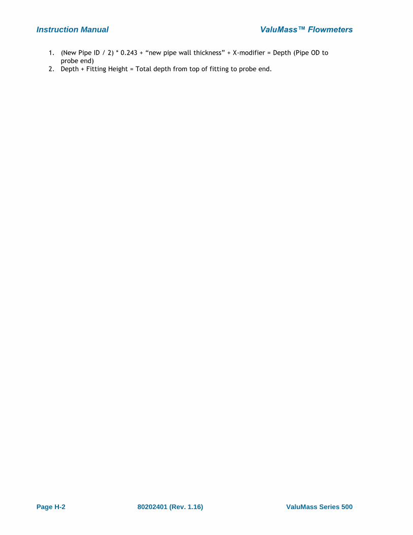
Instruction Manual ValuMass™ Flowmeters
Page H-2 80202401 (Rev. 1.16) ValuMass Series 500
1. (New Pipe ID / 2) * 0.243 + “new pipe wall thickness” + X-modifier = Depth (Pipe OD to
probe end)
2. Depth + Fitting Height = Total depth from top of fitting to probe end.
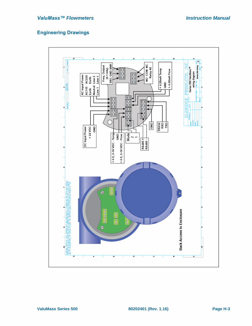
ValuMass™ Flowmeters Instruction Manual
ValuMass Series 500 80202401 (Rev. 1.16) Page H-3
Engineering Drawings
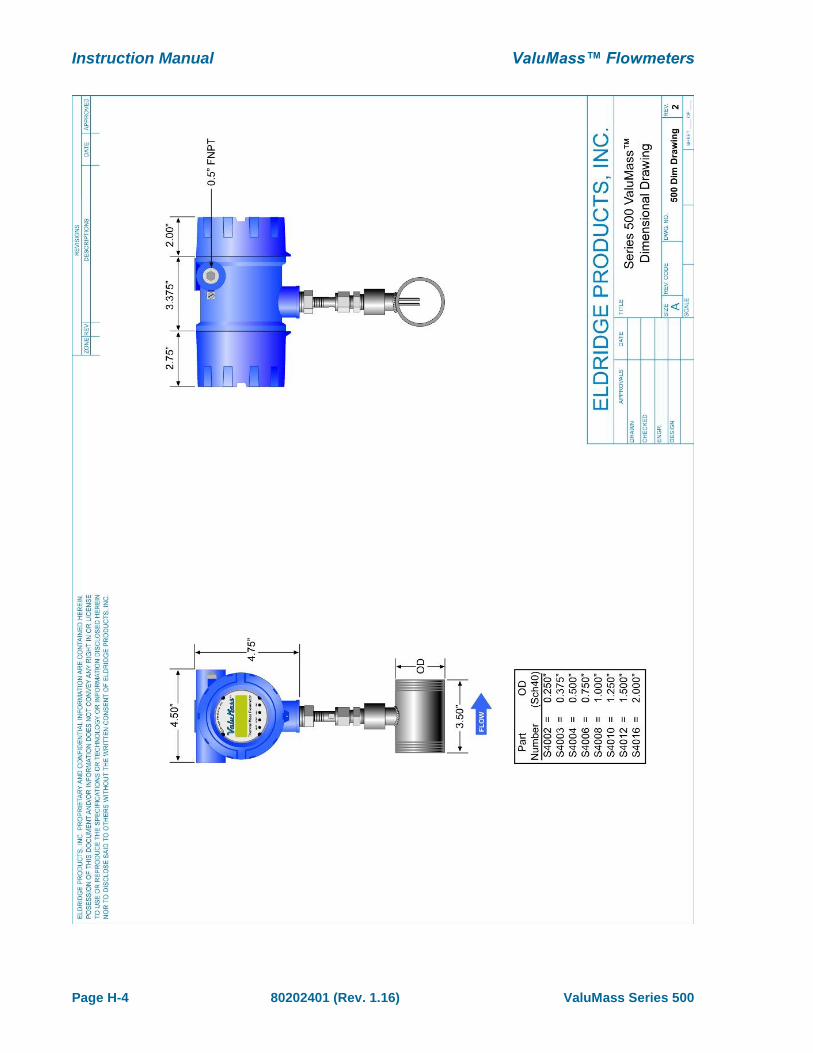
Instruction Manual ValuMass™ Flowmeters
Page H-4 80202401 (Rev. 1.16) ValuMass Series 500

ValuMass™ Flowmeters Instruction Manual
ValuMass Series 500 80202401 (Rev. 1.16) Page H-5
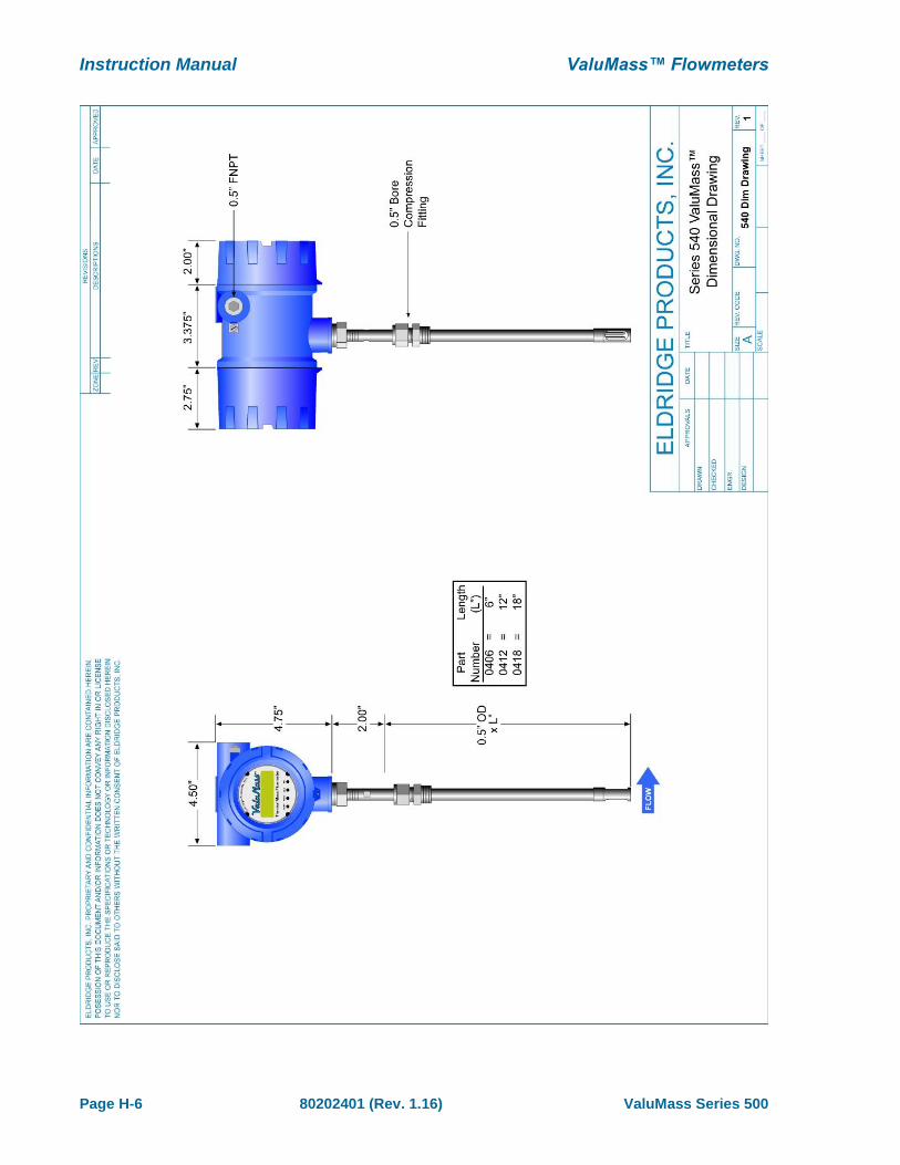
Instruction Manual ValuMass™ Flowmeters
Page H-6 80202401 (Rev. 1.16) ValuMass Series 500
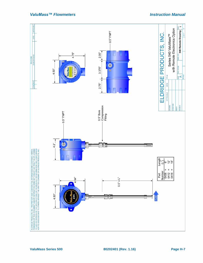
ValuMass™ Flowmeters Instruction Manual
ValuMass Series 500 80202401 (Rev. 1.16) Page H-7
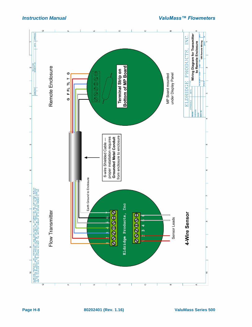
Instruction Manual ValuMass™ Flowmeters
Page H-8 80202401 (Rev. 1.16) ValuMass Series 500

ValuMass™ Flowmeters Instruction Manual
ValuMass Series 500 80202401 (Rev. 1.16) Page H-9

Instruction Manual ValuMass™ Flowmeters
Page H-10 80202401 (Rev. 1.16) ValuMass Series 500
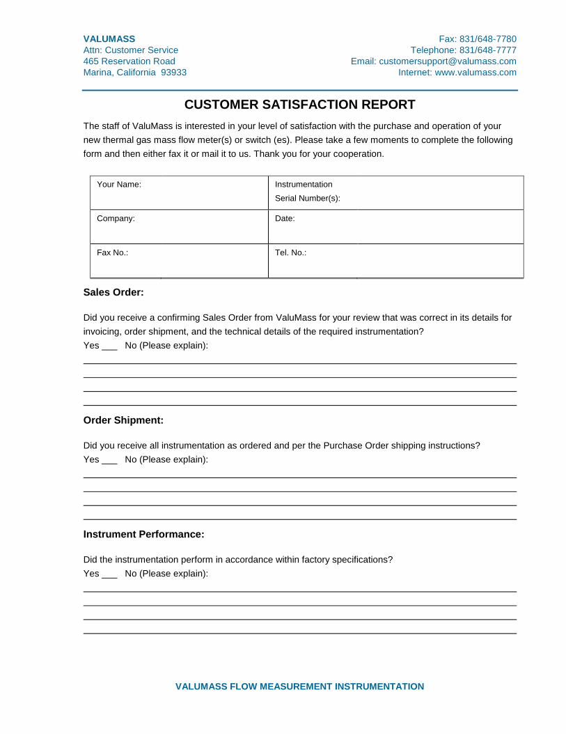
VALUMASS Fax: 831/648-7780
Attn: Customer Service Telephone: 831/648-7777
465 Reservation Road Email: [email protected]
Marina, California 93933 Internet: www.valumass.com
VALUMASS FLOW MEASUREMENT INSTRUMENTATION
CUSTOMER SATISFACTION REPORT
The staff of ValuMass is interested in your level of satisfaction with the purchase and operation of your
new thermal gas mass flow meter(s) or switch (es). Please take a few moments to complete the following
form and then either fax it or mail it to us. Thank you for your cooperation.
Your Name: Instrumentation
Serial Number(s):
Company:
Date:
Fax No.:
Tel. No.:
Sales Order:
Did you receive a confirming Sales Order from ValuMass for your review that was correct in its details for
invoicing, order shipment, and the technical details of the required instrumentation?
Yes ___ No (Please explain):
Order Shipment:
Did you receive all instrumentation as ordered and per the Purchase Order shipping instructions?
Yes ___ No (Please explain):
Instrument Performance:
Did the instrumentation perform in accordance within factory specifications?
Yes ___ No (Please explain):