Embed Size (px)
Citation preview

FIBROPLAN®
NC ROTARY TABLES WITH WORM GEAR UNIT
ROTOCUTTING ROTARY TABLES FOR MACHINE TOOLS

2 3
FIBRO – GLOBAL PIONEER FOR NC ROTARY TABLES AND INDEXING TABLES
FIBRO offers the most comprehensive
range of rotary tables worldwide from a
single source. After starting out in 1960
with a pneumatic rotary table, the product
range has since grown to include more
than 150 different rotary table types.
FIBRO rotary tables are used as posi-
tioning and feeding axes, as workhol-
ding devices in machine tools, as well as
in assembly and automation systems.
Tens of thousands of rotary table units
around the globe are now integrated in
high productivity machines as essential
components. The quality, efficient tech-
nology, and broad product range satisfy
the strict requirements of our customers.
With its strategically placed international
locations, FIBRO is your production
partner who brings proven solutions for
rotary table and NC applications around
the globe. FIBRO's experts are available
to assist in and beyond the planning
phase of projects.
COMPREHENSIVE SERVICE FROM
A SINGLE SOURCE
FIBRO – Global Pioneer

4 5
FIBROPLAN®
NC ROTARY TABLES WITH WORM
GEAR UNIT
FIBRODYN® DA
HIGHLY DYNAMIC NC ROTARY TABLES
WITH DIRECT TORQUE DRIVE
FIBROMAX®
HEAVY LOAD NC ROTARY TABLES
WITH TWIN DRIVE
FIBROTAKT®
HIGH-PRECISION NC ROTARY TABLES
WITH HIRTH FACE GEAR
SPECIAL SOLUTIONS
CUSTOMER SPECIFIC ROTARY TABLES
APPLICATION
ROTOCUTTING RANGEROTARY TABLES FOR MACHINE TOOLS
RotoCutting range
APPLICATION APPLICATION APPLICATION APPLICATION
Transport loads up to 20 t
Well suited for a large variety
of applications
Available as single or multiple
axis combination
Perfectly suitable for rotary
milling and simultaneous
machining
Extreme range of table top sizes
from 160 to 3,000 mm
Available in horizontal and
vertical version
18 sizes
Transport loads up to 400 t
Positioning as well as circular
and simultaneous multi-axis
machining
Available as a modular system,
integrated with linear slide or
standalone rotary table
High speeds and accelerations
with up to 2,000 rpm
Diverse operating modes with-
out rechucking: Positioning
mode, rotary, circular and simul-
taneous machining
Suitable for applications that
requires no mechanical backlash
Highest machining accuracy at
extreme speeds
For high-precision positioning
applications up to ± 1”, repeata-
bility up to ± 0.1”
No NC controller required
Hydraulically, electrically, or
pneumatically driven and con-
trolled
Also available as a built-in
version for integrated machine
constructions, e.g., special pur-
pose rotary transfer machines
Tailored rotary table solutions
for customer application, e.g.
Rotary table/multiple axis
combinations
Planetary tables
Built-in rotary table
Rotary tables integrated
with linear slide
Stand-alone rotary tables

6 7
FIBROPLAN®
AT A GLANCE
The FIBROPLAN NC rotary table
consists of a base unit with the
main mechanical components,
housing, table top, bearing and
Flexible positioning in freely
selectable angular steps
Positioning accuracy with corre-
sponding selection and arrange-
ment of the measuring system up
to ±10” (indirect) or ± 2.5” (direct)
High precision in terms of radial
and facial runout, due to selected,
preloaded radial/axial combina-
tion bearings of the largest
possible diameter
Accommodation of high machin-
ing forces and torques
FIBROPLAN®
TECHNICAL DESCRIPTION
Hydraulic table clamp for increa-
sing static strength with a simulta-
neous relief of the gearing system
Reliable for simultaneous machi-ning
due to preloaded bearings and ad-
justable worm gearing to achieve
near zero backlash
High operating safety and a long
operating life due to a careful struc-
tural design
Low maintenance due to life-time
lubrication
Wide variety of batch-produced
standard models with many variants
selectable from a modular supple-
mentary system
Multiple axis designs and combi-
nations with slide tables
Designs with a pallet clamping
device and pallets
Special solutions for special applica-
tions
1 Table top
2 Worm gear attached to
the table top
3 Bearing
4 Worm with adjus-
table backlash
5 Housing
6 Ring piston for
hydraulic clamping
7 Flexible disc for
hydraulic clamping
gearbox, additional assemblies,
hydraulic clamping, measuring
system and drive motor. Optional
accessories such as the NC con-
trol and comprehensive acces-
sories permit expansion into a
complete, NC-controlled rotary
and positioning axis.
FIBROPLAN®
FIBROPLAN NC rotary tables are char-
acterised by a CNC controlled circular
milling and positioning movement. They
are used in a variety of machine types,
controlled either by a drive unit within the
machine tool or a separate CNC con-
troller. The modern design with a rigid
mechanical structure, combined with
high-quality drive and control elements,
which offers great advantages.
STYLES, SIZES AND PERFOR-
MANCE DATA
The FIBROPLAN manufacturing program
offers a wide range of types, sizes and
performance specifications and allows
an ideal product selection for each indi-
vidual application. The following styles
are available:
The Standard style is designed main-
ly for horizontal use (in relation to the
surface of the table top). The structur-
al design is compact and the height is
kept very low. This ensures maximum
utilization of the machine tool's working
space and highest rigidity. In the case of
sizes 2 through 4, vertical use is possible
due to a second mounting surface.
The Vertical Style is designed mainly
for vertical use (in relation to the surface
of the table top). The structural design
is compact with a relatively low center
height. Vertical rotary tables are coordi-
nated with the counter bearings in regard
to height. A horizontal use is also possible.
Multiple axis designs, e.g., for 5-axis
machining and machining tasks with
complicated angles. Designs with a pal-
let clamping device for accommodating
pallets and machine-integrated designs.
For all applications, we offer qualified
consulting with our entire experience as
a rotary table specialist.
3
5 6 7
2
1
4

8 9
FIBROPLAN® STANDARDHORIZONTAL USE POSITION
FIBROPLAN® VERTICAL TYPEVERTICAL USE POSITION
Range overview
TYPES AND PAGE NUMBERS TYPES AND PAGE NUMBERS
NC. 1.02
PAGE 10
NC. 1.03
PAGE 12
NC. 1.04
PAGE 14
NC. 1.05
PAGE 16
NC. 1.06
PAGE 18
NC. 1.07
PAGE 20
NC. 1.08
PAGE 22
NC. 1.09
PAGE 24
NC. 1.10
PAGE 26
NC. 2.01
PAGE 28
NC. 1.02
PAGE 10
NC. 1.03
PAGE 12
NC. 1.04
PAGE 14
NC. 2.05
PAGE 30
NC. 2.06
PAGE 32
NC. 2.07
PAGE 34
NC. 2.08
PAGE 36
NC. 2.09
PAGE 38
NC. 2.10
PAGE 40
MAIN DIMENSIONS
Table top Ø mm 240/280 340/400 420/500 180 520/630 630/800 800/1,000 1,000/1,250 1,250/1,500 1,600
Overall height mm 180 245 280 130 360 360/440 440/550 550/670 670/800 900
Bearing Ø mm 120x210 200x300 260x385 80 ×150 325×450 460×600 580×750 650×870 850×1,095 1,030×1,300
LOAD DATA
Permissible axial loading on the table top N 9,000 9,000 10,000 5,000 45,000 75,000 100,000 120,000 160,000 200,000
permitted transport load kg 250 300 400 150 1,200 2,000 3,000 6,000 8,000 12,000
Permissible tilting moment Nm 2,000 2,000 3,200 1,500 16,000 26,000 32,000 48,000 60,000 110,000
Permissible torque during rotary milling transmitted by worm gear unit Nm 850 1,900 3,400 300 4,200 7,000 7,000 14,000 17,000 24,000
Permissible tangential mo-ment with hydraulic clamping Nm 1,200 2,000 4,000 700 6,000 8,000 14,000 25,000 32,000 40,000
PRECISION
Indexing precision with indirect measurement in arc seconds, max. – ± 15 ± 15 ± 10 ± 20 ± 10 ± 10 ± 10 ± 10 ± 10 ± 10
with direct measurement in arc seconds dependent on measuring system, max. – ± 3 ± 3 ± 3 ± 3 ± 3 ± 3 ± 3 ± 3 ± 3 ± 3
Axial runout of the center bore measured at the table top (TIR) mm 0.01 0.01 0.01 0.01 0.01 0.01 0.01 0.01 0.01 0.01
Axial runout of the table top mm 0.01 0.01 0.01 0.01 0.012 0.015 0.015 0.02 0.02 0.025
DRIVE DATA
Ratio i tot 120/240 72/144 120/240 144 240 288 360 480 480 480
Max. speed of table top rpm 12.5 27.5 10 27.5 10 8 6 6 6 6
MAIN DIMENSIONS
Table top Ø mm 240/280 340/400 420/500 520/630 630/800 800/1,000 1,000/1,250 1,250/1,500 1,600
Overall height mm 190 190 210 205 225 250 290 350 370
Bearing Ø mm 120×210 200×300 260×385 325×450 395x525 460x600 650×870 850×1,095 1,030×1,300
LOAD DATA
Permissible axial loading on the table top N 25,000 35,000 40,000 55,000 75,000 100,000 180,000 240,000 350,000
permitted transport load kg 800 1,000 1,200 2,500 3,500 6,000 10,000 12,000 20,000
Permissible tilting moment Nm 3,200 5,000 8,000 16,000 20,000 26,000 60,000 80,000 150,000
Permissible torque during rotary milling transmitted by worm gear unit Nm 850 1,900 3,500 4,200 7,000 7,000 14,000 17,000 24,000
Permissible tangential mo-ment with hydraulic clamping Nm 1,200 2,000 4,000 6,000 8,000 14,000 25,000 32,000 40,000
PRECISION
Component precision with indirect measurement in arc seconds, max. – ± 15 ± 15 ± 10 ± 10 ± 10 ± 10 ± 10 ± 10 ± 10
with direct measurement in arc seconds dependent on measuring system, max. – ± 3 ± 3 ± 3 ± 3 ± 3 ± 3 ± 3 ± 3 ± 3
Axial runout of the center bore measured at the table top (TIR) mm 0.01 0.01 0.01 0.01 0.01 0.01 0.01 0.01 0.01
Axial runout of the table top mm 0.01 0.01 0.01 0.012 0.015 0.015 0.02 0.02 0.025
DRIVE DATA
Ratio i tot 72/144 120/240 120/240 240 288 360 480 480 480
Max. speed of table top rpm 27.5 12.5 10 10 8 6 6 6 6
Subject to change without notice.
10 11
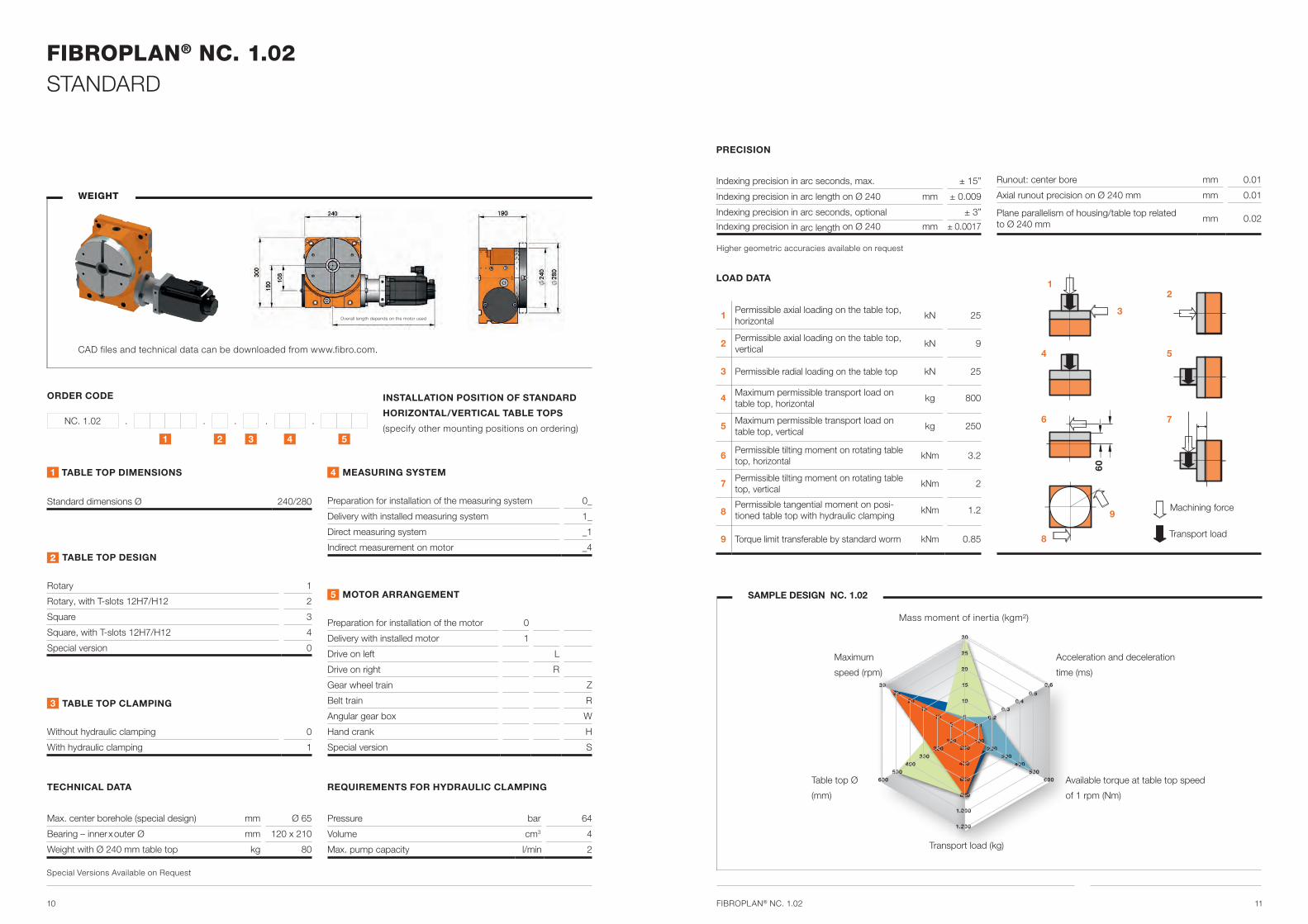
FIBROPLAN® NC. 1.02STANDARD
1 2 3 4 5
ORDER CODE
NC. 1.02 . . . . .
WEIGHT
1 TABLE TOP DIMENSIONS
Standard dimensions Ø 240/280
2 TABLE TOP DESIGN
Rotary 1
Rotary, with T-slots 12H7/H12 2
Square 3
Square, with T-slots 12H7/H12 4
Special version 0
3 TABLE TOP CLAMPING
Without hydraulic clamping 0
With hydraulic clamping 1
4 MEASURING SYSTEM
Preparation for installation of the measuring system 0_
Delivery with installed measuring system 1_
Direct measuring system _1
Indirect measurement on motor _4
5 MOTOR ARRANGEMENT
Preparation for installation of the motor 0
Delivery with installed motor 1
Drive on left L
Drive on right R
Gear wheel train Z
Belt train R
Angular gear box W
Hand crank H
Special version S
TECHNICAL DATA
Max. center borehole (special design) mm Ø 65
Bearing – inner x outer Ø mm 120 x 210
Weight with Ø 240 mm table top kg 80
INSTALLATION POSITION OF STANDARD
HORIZONTAL/VERTICAL TABLE TOPS
(specify other mounting positions on ordering)
Pressure bar 64
Volume cm3 4
Max. pump capacity l/min 2
CAD files and technical data can be downloaded from www.fibro.com.
Overall length depends on the motor used
PRECISION
Indexing precision in arc seconds, max. ± 15”
Indexing precision in arc length on Ø 240 mm ± 0.009
Indexing precision in arc seconds, optional ± 3”
Indexing precision in arc length on Ø 240 mm ± 0.0017
9
Transport load
Machining force
1
3
8
4
Runout: center bore mm 0.01
Axial runout precision on Ø 240 mm mm 0.01
Plane parallelism of housing/table top related to Ø 240 mm
mm 0.02
LOAD DATA
1 Permissible axial loading on the table top, horizontal
kN 25
2 Permissible axial loading on the table top, vertical
kN 9
3 Permissible radial loading on the table top kN 25
4 Maximum permissible transport load on table top, horizontal
kg 800
5 Maximum permissible transport load on table top, vertical
kg 250
6 Permissible tilting moment on rotating table top, horizontal
kNm 3.2
7 Permissible tilting moment on rotating table top, vertical
kNm 2
8Permissible tangential moment on posi-tioned table top with hydraulic clamping
kNm 1.2
9 Torque limit transferable by standard worm kNm 0.85
6
2
7
5
60
SAMPLE DESIGN NC. 1.02
Maximum
speed (rpm)
Transport load (kg)
Acceleration and deceleration
time (ms)
Available torque at table top speed
of 1 rpm (Nm)
Table top Ø
(mm)
Mass moment of inertia (kgm²)
FIBROPLAN® NC. 1.02
Higher geometric accuracies available on request
Special Versions Available on Request
REQUIREMENTS FOR HYDRAULIC CLAMPING
5 5 10
1015
15
20
20
25
25
30
30
100200
400
600
800
1.000
1.200
100
0,6
0,5
0,10,2
0,30,4
0
200 200300 300
400 400500 500
600 600

12 13
FIBROPLAN® NC. 1.03STANDARD
FIBROPLAN® NC. 1.03
9
1
3
8
4
6
2
7
5
65
WEIGHT
CAD files and technical data can be downloaded from www.fibro.com.
PRECISION
Indexing precision in arc seconds, max. ± 15”
Indexing precision in arc length on Ø 340 mm ± 0.012
Indexing precision in arc seconds, optional ± 3”
Indexing precision in arc length on Ø 340 mm ± 0.0025
Runout: center bore mm 0.01
Axial runout precision on Ø 340 mm mm 0.01
Plane parallelism of housing/table top related to Ø 340 mm
mm 0.02
LOAD DATA
1 Permissible axial loading on the table top, horizontal
kN 35
2 Permissible axial loading on the table top, vertical
kN 9
3 Permissible radial loading on the table top kN 40
4 Maximum permissible transport load on table top, horizontal
kg 1,000
5 Maximum permissible transport load on table top, vertical
kg 300
6 Permissible tilting moment on rotating table top, horizontal
kNm 5
7 Permissible tilting moment on rotating table top, vertical
kNm 2
8Permissible tangential moment on posi-tioned table top with hydraulic clamping
kNm 2
9 Torque limit transferable by standard worm kNm 1.9Transport load
Machining force
1 2 3 4 5
ORDER CODE
NC. 1.03 . . . . .
INSTALLATION POSITION OF STANDARD
HORIZONTAL/VERTICAL TABLE TOPS
(specify other mounting positions on ordering)
SAMPLE DESIGN NC. 1.03
Maximum
speed (rpm)
Transport load (kg)
Acceleration and deceleration
time (ms)
Table top Ø
(mm)
1 TABLE TOP DIMENSIONS
Standard dimensions Ø 340/400
2 TABLE TOP DESIGN
Rotary 1
Rotary, with T-slots 14H7/H12 2
Square 3
Square, with T-slots 14H7/H12 4
Special version 0
3 TABLE TOP CLAMPING
Without hydraulic clamping 0
With hydraulic clamping 1
4 MEASURING SYSTEM
Preparation for installation of the measuring system 0_
Delivery with installed measuring system 1_
Direct measuring system _1
Indirect measurement on motor _4
5 MOTOR ARRANGEMENT
Preparation for installation of the motor 0
Delivery with installed motor 1
Drive on left L
Drive on right R
Gear wheel train Z
Belt train R
Angular gear box W
Hand crank H
Special version S
TECHNICAL DATA
Max. center borehole (special design) mm Ø 110
Bearing – inner x outer Ø mm 200 x 300
Weight with Ø 240 mm table top kg 170
Pressure bar 64
Volume cm3 4
Max. pump capacity l/min 2
Overall length depends on the motor used
Special Versions Available on Request
REQUIREMENTS FOR HYDRAULIC CLAMPING
Mass moment of inertia (kgm²)
Higher geometric accuracies available on request
Available torque at table top speed
of 1 rpm (Nm)
5 15 10
3015
45
20
60
25
75
30
90
100200
400
600
800
1.000
1.200
100
0,6
0,5
0,10,2
0,30,4
0
200 200300 300
400 400500 500
600 600

14 15
FIBROPLAN® NC. 1.04 STANDARD
FIBROPLAN® NC. 1.04
9
1
3
8
4
6
2
7
5
80
WEIGHT
CAD files and technical data can be downloaded from www.fibro.com.
Transport load
Machining force
1 2 3 4 5
ORDER CODE
NC. 1.04 . . . . .
PRECISION
Indexing precision in arc seconds, max. ± 10”
Indexing precision in arc length on Ø 420 mm ± 0.010
Indexing precision in arc seconds, optional ± 3”
Indexing precision in arc length on Ø 420 mm ± 0.003
Runout: center bore mm 0.01
Axial runout precision on Ø 420 mm mm 0.01
Plane parallelism of housing/table top related to Ø 420 mm
mm 0.02
LOAD DATA
1 Permissible axial loading on the table top, horizontal
kN 40
2 Permissible axial loading on the table top, vertical
kN 10
3 Permissible radial loading on the table top kN 50
4 Maximum permissible transport load on table top, horizontal
kg 1,200
5 Maximum permissible transport load on table top, vertical
kg 400
6 Permissible tilting moment on rotating table top, horizontal
kNm 8
7 Permissible tilting moment on rotating table top, vertical
kNm 3.2
8Permissible tangential moment on posi-tioned table top with hydraulic clamping
kNm 4
9 Torque limit transferable by standard worm kNm 3.5
INSTALLATION POSITION OF STANDARD
HORIZONTAL/VERTICAL TABLE TOPS
(specify other mounting positions on ordering)
SAMPLE DESIGN NC. 1.04
Maximum
speed (rpm)
Transport load (kg)
Acceleration and deceleration
time (ms)
Table top Ø
(mm)
1 TABLE TOP DIMENSIONS
Standard dimensions Ø 420/500
2 TABLE TOP DESIGN
Rotary 1
Rotary, with T-slots 14H7/H12 2
Square 3
Square, with T-slots 14H7/H12 4
Special version 0
3 TABLE TOP CLAMPING
Without hydraulic clamping 0
With hydraulic clamping 1
4 MEASURING SYSTEM
Preparation for installation of the measuring system 0_
Delivery with installed measuring system 1_
Direct measuring system _1
Indirect measurement on motor _4
5 MOTOR ARRANGEMENT
Preparation for installation of the motor 0
Delivery with installed motor 1
Drive on left L
Drive on right R
Gear wheel train Z
Belt train R
Angular gear box W
Hand crank H
Special version S
TECHNICAL DATA
Max. center borehole (special design) mm Ø 140
Bearing – inner x outer Ø mm 260 x 385
Weight with Ø 240 mm table top kg 270
Pressure bar 64
Volume cm3 6
Max. pump capacity l/min 3
Overall length depends on the motor used
Special Versions Available on Request
REQUIREMENTS FOR HYDRAULIC CLAMPING
Mass moment of inertia (kgm²)
Higher geometric accuracies available on request
Available torque at table top speed
of 1 rpm (Nm)
25 50 50
100
150
200
250
300
75100
125150
125200
400
600
800
1.000
1.200
250
2
1,8
0,30,6
0,91,2
0
250 500375 750
500 1.000625 1.250
750 1.500

16 17
FIBROPLAN® NC. 1.05 STANDARD
FIBROPLAN® NC. 1.05
9
1
3
8
4
6
85
WEIGHT
CAD files and technical data can be downloaded from www.fibro.com.
Transport load
Machining force
1 2 3 4 5
ORDER CODE
NC. 1.05 . . . . .
PRECISION
Indexing precision in arc seconds, max. ± 10”
Indexing precision in arc length on Ø 520 mm ± 0.013
Indexing precision in arc seconds, optional ± 3”
Indexing precision in arc length on Ø 520 mm ± 0.004
Runout: center bore mm 0.01
Axial runout precision on Ø 520 mm mm 0.012
Plane parallelism of housing/table top related to Ø 520 mm
mm 0.025
LOAD DATA
1 Permissible axial loading on the table top, horizontal
kN 55
3 Permissible radial loading on the table top kN 65
4 Maximum permissible transport load on table top, horizontal
kg 2,500
6 Permissible tilting moment on rotating table top, horizontal
kNm 16
8Permissible tangential moment on posi-tioned table top with hydraulic clamping
kNm 6
9 Torque limit transferable by standard worm kNm 4.2
INSTALLATION POSITION OF STANDARD
HORIZONTAL TABLE TOPS
(specify other mounting positions on ordering)
SAMPLE DESIGN NC. 1.05
Maximum
speed (rpm)
Transport load (kg)
Acceleration and deceleration
time (ms)
Table top Ø
(mm)
1 TABLE TOP DIMENSIONS
Standard dimensions Ø 520/630
2 TABLE TOP DESIGN
Rotary 1
Rotary, with T-slots 14H7/H12 2
Square 3
Square, with T-slots 14H7/H12 4
Special version 0
3 TABLE TOP CLAMPING
Without hydraulic clamping 0
With hydraulic clamping 1
4 MEASURING SYSTEM
Preparation for installation of the measuring system 0_
Delivery with installed measuring system 1_
Direct measuring system _1
Indirect measurement on motor _4
5 MOTOR ARRANGEMENT
Preparation for installation of the motor 0
Delivery with installed motor 1
Drive on left L
Drive on right R
Gear wheel train Z
Belt train R
Angular gear box W
Hand crank H
Special version S
TECHNICAL DATA
Max. center borehole (special design) mm Ø 140
Bearing – inner x outer Ø mm 325 x 450
Weight with Ø 240 mm table top kg 360
Pressure bar 64
Volume cm3 8
Max. pump capacity l/min 4
Overall length depends on the motor used
Special Versions Available on Request
REQUIREMENTS FOR HYDRAULIC CLAMPING
Mass moment of inertia (kgm²)
Higher geometric accuracies available on request
Available torque at table top speed
of 1 rpm (Nm)
50125100
250
375
500
625
750
150200
250300
1251.000
2.000
3.000
4.000
5.000
6.000
2000
250 400375 600
500 800625 1.000
750 1.200
0,9
0,75
0,150,30
0,450,60

18 19
FIBROPLAN® NC. 1.06 STANDARD
FIBROPLAN® NC. 1.06
9
1
3
8
4
6
100
WEIGHT
CAD files and technical data can be downloaded from www.fibro.com.
Transport load
Machining force
1 2 3 4 5
ORDER CODE
NC. 1.06 . . . . .
PRECISION
Indexing precision in arc seconds, max. ± 10”
Indexing precision in arc length on Ø 630 mm ± 0.015
Indexing precision in arc seconds, optional ± 3”
Indexing precision in arc length on Ø 630 mm ± 0.005
Runout: center bore mm 0.01
Axial runout precision on Ø 630 mm mm 0.015
Plane parallelism of housing/table top related to Ø 630 mm
mm 0.03
LOAD DATA
1 Permissible axial loading on the table top, horizontal
kN 75
3 Permissible radial loading on the table top kN 80
4 Maximum permissible transport load on table top, horizontal
kg 3,500
6 Permissible tilting moment on rotating table top, horizontal
kNm 20
8Permissible tangential moment on posi-tioned table top with hydraulic clamping
kNm 8
9 Torque limit transferable by standard worm kNm 7
INSTALLATION POSITION OF STANDARD
HORIZONTAL TABLE TOPS
(specify other mounting positions on ordering)
SAMPLE DESIGN NC. 1.06
Maximum
speed (rpm)
Transport load (kg)
Acceleration and deceleration
time (ms)
Table top Ø
(mm)
1 TABLE TOP DIMENSIONS
Standard dimensions Ø 630/800
2 TABLE TOP DESIGN
Rotary 1
Rotary, with T-slots 18H7/H12 2
Square 3
Square, with T-slots 18H7/H12 4
Special version 0
3 TABLE TOP CLAMPING
Without hydraulic clamping 0
With hydraulic clamping 1
4 MEASURING SYSTEM
Preparation for installation of the measuring system 0_
Delivery with installed measuring system 1_
Direct measuring system _1
Indirect measurement on motor _4
5 MOTOR ARRANGEMENT
Preparation for installation of the motor 0
Delivery with installed motor 1
Drive on left L
Drive on right R
Gear wheel train Z
Belt train R
Angular gear box W
Hand crank H
Special version S
TECHNICAL DATA
Max. center borehole (special design) mm Ø 190
Bearing – inner x outer Ø mm 395 x 525
Weight with Ø 240 mm table top kg 550
Pressure bar 64
Volume cm3 10
Max. pump capacity l/min 5
Overall length depends on the motor used
Special Versions Available on Request
REQUIREMENTS FOR HYDRAULIC CLAMPING
Mass moment of inertia (kgm²)
Higher geometric accuracies available on request
Available torque at table top speed
of 1 rpm (Nm)
1520030
400
600
800
1.000
1.200
4560
7590
2251.000
2.000
3.000
4.000
5.000
6.000
5000
450 1.000675 1.500
900 2.0001.125 2.500
1.350 3.000
3,0
2,5
0,51,0
1,52,0

20 21
FIBROPLAN® NC. 1.07 STANDARD
FIBROPLAN® NC. 1.07
9
1
3
8
4
6
110
WEIGHT
CAD files and technical data can be downloaded from www.fibro.com.
Transport load
Machining force
1 2 3 4 5
ORDER CODE
NC. 1.07 . . . . .
PRECISION
Indexing precision in arc seconds, max. ± 10”
Indexing precision in arc length on Ø 800 mm ± 0.020
Indexing precision in arc seconds, optional ± 3”
Indexing precision in arc length on Ø 800 mm ± 0.005
Runout: center bore mm 0.01
Axial runout precision on Ø 800 mm mm 0.015
Plane parallelism of housing/table top related to Ø 800 mm
mm 0.03
LOAD DATA
1 Permissible axial loading on the table top, horizontal
kN 100
3 Permissible radial loading on the table top kN 115
4 Maximum permissible transport load on table top, horizontal
kg 6,000
6 Permissible tilting moment on rotating table top, horizontal
kNm 26
8Permissible tangential moment on posi-tioned table top with hydraulic clamping
kNm 14
9 Torque limit transferable by standard worm kNm 7
INSTALLATION POSITION OF STANDARD
HORIZONTAL TABLE TOPS
(specify other mounting positions on ordering)
SAMPLE DESIGN NC. 1.07
Maximum
speed (rpm)
Transport load (kg)
Acceleration and deceleration
time (ms)
Table top Ø
(mm)
1 TABLE TOP DIMENSIONS
Standard dimensions Ø 800/1,000
2 TABLE TOP DESIGN
Rotary 1
Rotary, with T-slots 18H7/H12 2
Square 3
Square, with T-slots 18H7/H12 4
Special version 0
3 TABLE TOP CLAMPING
Without hydraulic clamping 0
With hydraulic clamping 1
4 MEASURING SYSTEM
Preparation for installation of the measuring system 0_
Delivery with installed measuring system 1_
Direct measuring system _1
Indirect measurement on motor _4
5 MOTOR ARRANGEMENT
Preparation for installation of the motor 0
Delivery with installed motor 1
Drive on left L
Drive on right R
Gear wheel train Z
Belt train R
Angular gear box W
Hand crank H
Special version S
TECHNICAL DATA
Max. center borehole (special design) mm Ø 250
Bearing – inner x outer Ø mm 460 x 600
Weight with Ø 240 mm table top kg 920
Pressure bar 64
Volume cm3 12
Max. pump capacity l/min 6
Overall length depends on the motor used
Special Versions Available on Request
REQUIREMENTS FOR HYDRAULIC CLAMPING
Mass moment of inertia (kgm²)
Higher geometric accuracies available on request
Available torque at table top speed
of 1 rpm (Nm)
1030020
600
900
1.200
1.500
1.800
3040
5060
2501.000
2.000
3.000
4.000
5.000
6.000
4500
500 900750 1.350
1.000 1.8001.250 2.250
1.500 2.700
9,0
7,5
1,53,0
4,56,0

22 23
FIBROPLAN® NC. 1.08STANDARD
FIBROPLAN® NC. 1.08
9
1
3
8
4
6
130
WEIGHT
CAD files and technical data can be downloaded from www.fibro.com.
Transport load
Machining force
1 2 3 4 5
ORDER CODE
NC. 1.08 . . . . .
PRECISION
Indexing precision in arc seconds, max. ± 10”
Indexing precision in arc length on Ø 1,000 mm ± 0.024
Indexing precision in arc seconds, optional ± 3”
Indexing precision in arc length on Ø 1,000 mm ± 0.007
Runout: center bore mm 0.01
Axial runout precision on Ø 1,000 mm mm 0.02
Plane parallelism of housing/table top related to Ø 1,000 mm
mm 0.04
LOAD DATA
1 Permissible axial loading on the table top, horizontal
kN 180
3 Permissible radial loading on the table top kN 250
4 Maximum permissible transport load on table top, horizontal
kg 10,000
6 Permissible tilting moment on rotating table top, horizontal
kNm 60
8Permissible tangential moment on posi-tioned table top with hydraulic clamping
kNm 25
9 Torque limit transferable by standard worm kNm 14
INSTALLATION POSITION OF STANDARD
HORIZONTAL TABLE TOPS
(specify other mounting positions on ordering)
SAMPLE DESIGN NC. 1.08
Maximum
speed (rpm)
Transport load (kg)
Acceleration and deceleration
time (ms)
Table top Ø
(mm)
1 TABLE TOP DIMENSIONS
Standard dimensions Ø 1,000/1,250
2 TABLE TOP DESIGN
Rotary 1
Rotary, with T-slots 22H7/H12 2
Square 3
Square, with T-slots 22H7/H12 4
Special version 0
3 TABLE TOP CLAMPING
Without hydraulic clamping 0
With hydraulic clamping 1
4 MEASURING SYSTEM
Preparation for installation of the measuring system 0_
Delivery with installed measuring system 1_
Direct measuring system _1
Indirect measurement on motor _4
5 MOTOR ARRANGEMENT
Preparation for installation of the motor 0
Delivery with installed motor 1
Drive on left L
Drive on right R
Gear wheel train Z
Belt train R
Angular gear box W
Hand crank H
Special version S
TECHNICAL DATA
Max. center borehole (special design) mm Ø 420
Bearing – inner x outer Ø mm 650 x 870
Weight with Ø 240 mm table top kg 1,550
Pressure bar 64
Volume cm3 15
Max. pump capacity l/min 7
Overall length depends on the motor used
Special Versions Available on Request
REQUIREMENTS FOR HYDRAULIC CLAMPING
Mass moment of inertia (kgm²)
Higher geometric accuracies available on request
Available torque at table top speed
of 1 rpm (Nm)
13.5002
7.000
10.500
14.000
17.500
21.000
34
56
3002.500
5.000
7.500
10.000
12.500
15.000
2.0000
600 4.000800 6.000
1.200 8.0001.500 10.000
1.800 12.000
0,6
0,5
0,10,2
0,30,4

24 25
FIBROPLAN® NC. 1.09 STANDARD
FIBROPLAN® NC. 1.09
9
1
3
8
4
6
145
WEIGHT
CAD files and technical data can be downloaded from www.fibro.com.
Transport load
Machining force
1 2 3 4 5
ORDER CODE
NC. 1.09 . . . . .
PRECISION
Indexing precision in arc seconds, max. ± 10”
Indexing precision in arc length on Ø 1,250 mm ± 0.03
Indexing precision in arc seconds, optional ± 3”
Indexing precision in arc length on Ø 1,250 mm ± 0.009
Runout: center bore mm 0.01
Axial runout precision on Ø 1,250 mm mm 0.02
Plane parallelism of housing/table top related to Ø 1,250 mm
mm 0.04
LOAD DATA
1 Permissible axial loading on the table top, horizontal
kN 240
3 Permissible radial loading on the table top kN 300
4 Maximum permissible transport load on table top, horizontal
kg 15,000
6 Permissible tilting moment on rotating table top, horizontal
kNm 100
8Permissible tangential moment on posi-tioned table top with hydraulic clamping
kNm 32
9 Torque limit transferable by standard worm kNm 17
WEIGHT
Transport load
Machining force
INSTALLATION POSITION OF STANDARD
HORIZONTAL TABLE TOPS
(specify other mounting positions on ordering)
SAMPLE DESIGN NC. 1.09
Maximum
speed (rpm)
Transport load (kg)
Acceleration and deceleration
time (ms)
Table top Ø
(mm)
1 TABLE TOP DIMENSIONS
Standard dimensions Ø 1,250/1,500
2 TABLE TOP DESIGN
Rotary 1
Rotary, with T-slots 22H7/H12 2
Square 3
Square, with T-slots 22H7/H12 4
Special version 0
3 TABLE TOP CLAMPING
Without hydraulic clamping 0
With hydraulic clamping 1
4 MEASURING SYSTEM
Preparation for installation of the measuring system 0_
Delivery with installed measuring system 1_
Direct measuring system _1
Indirect measurement on motor _4
5 MOTOR ARRANGEMENT
Preparation for installation of the motor 0
Delivery with installed motor 1
Drive on left L
Drive on right R
Gear wheel train Z
Belt train R
Angular gear box W
Hand crank H
Special version S
TECHNICAL DATA
Max. center borehole (special design) mm Ø 520
Bearing – inner x outer Ø mm 850 x 1,095
Weight with Ø 240 mm table top kg 2,500
Pressure bar 64
Volume cm3 20
Max. pump capacity l/min 10
Overall length depends on the motor used
Special Versions Available on Request
REQUIREMENTS FOR HYDRAULIC CLAMPING
Mass moment of inertia (kgm²)
Higher geometric accuracies available on request
Available torque at table top speed
of 1 rpm (Nm)
3.500
7.000
10.500
14.000
17.500
21.000
3503.500
7.000
10.500
14.000
17.500
21.000
0
7001.050
1.4001.750
2.100
65
12
34
1020
3040
5060
2.0004.000
6.0008.000
10.00012.000

26 27
FIBROPLAN® NC. 1.10 STANDARD
FIBROPLAN® NC. 1.10
9
1
3
8
4
6
170
WEIGHT
CAD files and technical data can be downloaded from www.fibro.com.
Transport load
Machining force
1 2 3 4 5
ORDER CODE
NC. 1.10 . . . . .
PRECISION
Indexing precision in arc seconds, max. ± 10”
Indexing precision in arc length on Ø 1,600 mm ± 0.039
Indexing precision in arc seconds, optional ± 3”
Indexing precision in arc length on Ø 1,600 mm ± 0.012
Runout: center bore mm 0.01
Axial runout precision at Ø 1,600 mm mm 0.025
Plane parallelism of housing/table top related to Ø 1,600 mm
mm 0.05
LOAD DATA
1 Permissible axial loading on the table top, horizontal
kN 350
3 Permissible radial loading on the table top kN 400
4 Maximum permissible transport load on table top, horizontal
kg 20,000
6 Permissible tilting moment on rotating table top, horizontal
kNm 150
8Permissible tangential moment on posi-tioned table top with hydraulic clamping
kNm 40
9 Torque limit transferable by standard worm kNm 24
INSTALLATION POSITION OF STANDARD
HORIZONTAL TABLE TOPS
(specify other mounting positions on ordering)
SAMPLE DESIGN NC. 1.10
Maximum
speed (rpm)
Transport load (kg)
Acceleration and deceleration
time (ms)
Table top Ø
(mm)
1 TABLE TOP DIMENSIONS
Standard dimensions Ø 1,600
2 TABLE TOP DESIGN
Rotary 1
Rotary, with T-slots 22H7/H12 2
Square 3
Square, with T-slots 22H7/H12 4
Special version 0
3 TABLE TOP CLAMPING
Without hydraulic clamping 0
With hydraulic clamping 1
4 MEASURING SYSTEM
Preparation for installation of the measuring system 0_
Delivery with installed measuring system 1_
Direct measuring system _1
Indirect measurement on motor _4
5 MOTOR ARRANGEMENT
Preparation for installation of the motor 0
Delivery with installed motor 1
Drive on left L
Drive on right R
Gear wheel train Z
Belt train R
Angular gear box W
Hand crank H
Special version S
TECHNICAL DATA
Max. center borehole (special design) mm Ø 630
Bearing – inner x outer Ø mm 1,030 x 1,300
Weight with Ø 240 mm table top kg 4,000
Pressure bar 64
Volume cm3 25
Max. pump capacity l/min 12
Overall length depends on the motor used
Special Versions Available on Request
REQUIREMENTS FOR HYDRAULIC CLAMPING
Mass moment of inertia (kgm²)
Higher geometric accuracies available on request
Available torque at table top speed
of 1 rpm (Nm)
15.000
30.000
45.000
60.000
75.000
90.000
5005.000
10.000
15.000
20.000
25.000
30.000
5.0000
1.000 10.0001.500 15.000
2.000 20.0002.500 25.000
3.000 30.000
9075
1530
4560
1020
3040
5060
28 29
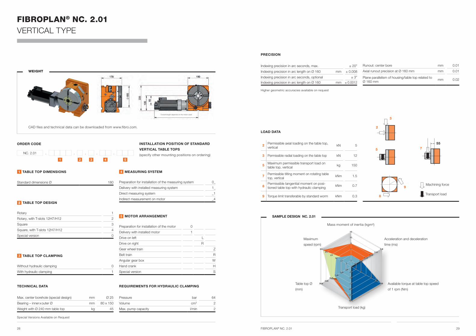
FIBROPLAN® NC. 2.01 VERTICAL TYPE
FIBROPLAN® NC. 2.01
3
2
75
9
8
55
WEIGHT
CAD files and technical data can be downloaded from www.fibro.com.
Transport load
Machining force
1 2 3 4 5
ORDER CODE
NC. 2.01 . . . . .
PRECISION
Indexing precision in arc seconds, max. ± 20”
Indexing precision in arc length on Ø 160 mm ± 0.008
Indexing precision in arc seconds, optional ± 3”
Indexing precision in arc length on Ø 160 mm ± 0.0012
Runout: center bore mm 0.01
Axial runout precision at Ø 160 mm mm 0.01
Plane parallelism of housing/table top related to Ø 160 mm
mm 0.02
LOAD DATA
2 Permissible axial loading on the table top, vertical
kN 5
3 Permissible radial loading on the table top kN 12
5 Maximum permissible transport load on table top, vertical
kg 150
7 Permissible tilting moment on rotating table top, vertical
kNm 1.5
8Permissible tangential moment on posi-tioned table top with hydraulic clamping
kNm 0.7
9 Torque limit transferable by standard worm kNm 0.3
INSTALLATION POSITION OF STANDARD
VERTICAL TABLE TOPS
(specify other mounting positions on ordering)
SAMPLE DESIGN NC. 2.01
Maximum
speed (rpm)
Transport load (kg)
Acceleration and deceleration
time (ms)
Table top Ø
(mm)
1 TABLE TOP DIMENSIONS
Standard dimensions Ø 180
2 TABLE TOP DESIGN
Rotary 1
Rotary, with T-slots 12H7/H12 2
Square 3
Square, with T-slots 12H7/H12 4
Special version 0
3 TABLE TOP CLAMPING
Without hydraulic clamping 0
With hydraulic clamping 1
4 MEASURING SYSTEM
Preparation for installation of the measuring system 0_
Delivery with installed measuring system 1_
Direct measuring system _1
Indirect measurement on motor _4
5 MOTOR ARRANGEMENT
Preparation for installation of the motor 0
Delivery with installed motor 1
Drive on left L
Drive on right R
Gear wheel train Z
Belt train R
Angular gear box W
Hand crank H
Special version S
TECHNICAL DATA
Max. center borehole (special design) mm Ø 25
Bearing – inner x outer Ø mm 80 x 150
Weight with Ø 240 mm table top kg 45
Pressure bar 64
Volume cm3 2
Max. pump capacity l/min 2
Overall length depends on the motor used
Special Versions Available on Request
REQUIREMENTS FOR HYDRAULIC CLAMPING
Mass moment of inertia (kgm²)
Higher geometric accuracies available on request
Available torque at table top speed
of 1 rpm (Nm)
5025
50
75
100
125
150
250
100 50
150 75
200 100
250 125300 150
510
1520
2530
2
4
6
8
10
12
0,6
0,5
0,10,2
0,30,4

30 31FIBROPLAN® NC. 2.05
3
2
75
9
8
90
WEIGHT
CAD files and technical data can be downloaded from www.fibro.com.
Transport load
Machining force
FIBROPLAN® NC. 2.05 VERTICAL TYPE
1 2 3 4 5
ORDER CODE
NC. 2.05 . . . . .
PRECISION
Indexing precision in arc seconds, max. ± 10”
Indexing precision in arc length on Ø 520 mm ± 0.013
Indexing precision in arc seconds, optional ± 3”
Indexing precision in arc length on Ø 520 mm ± 0.004
Runout: center bore mm 0.01
Axial runout precision on Ø 520 mm mm 0.012
Plane parallelism of housing/table top related to Ø 520 mm
mm 0.025
LOAD DATA
2 Permissible axial loading on the table top, vertical
kN 45
3 Permissible radial loading on the table top kN 65
5 Maximum permissible transport load on table top, vertical
kg 1,200
7 Permissible tilting moment on rotating table top, vertical
kNm 16
8Permissible tangential moment on posi-tioned table top with hydraulic clamping
kNm 6
9 Torque limit transferable by standard worm kNm 4.2
INSTALLATION POSITION OF STANDARD
VERTICAL TABLE TOPS
(specify other mounting positions on ordering)
SAMPLE DESIGN NC. 2.05
Maximum
speed (rpm)
Transport load (kg)
Acceleration and deceleration
time (ms)
Table top Ø
(mm)
1 TABLE TOP DIMENSIONS
Standard dimensions Ø 520/630
2 TABLE TOP DESIGN
Rotary 1
Rotary, with T-slots 14H7/H12 2
Square 3
Square, with T-slots 14H7/H12 4
Special version 0
3 TABLE TOP CLAMPING
Without hydraulic clamping 0
With hydraulic clamping 1
4 MEASURING SYSTEM
Preparation for installation of the measuring system 0_
Delivery with installed measuring system 1_
Direct measuring system _1
Indirect measurement on motor _4
5 MOTOR ARRANGEMENT
Preparation for installation of the motor 0
Delivery with installed motor 1
Drive on left L
Drive on right R
Gear wheel train Z
Belt train R
Angular gear box W
Hand crank H
Special version S
TECHNICAL DATA
Max. center borehole (special design) mm Ø 190
Bearing – inner x outer Ø mm 325 x 450
Weight with Ø 240 mm table top kg 500
Pressure bar 64
Volume cm3 16
Max. pump capacity l/min 8
Overall length depends on the motor used
Special Versions Available on Request
REQUIREMENTS FOR HYDRAULIC CLAMPING
Mass moment of inertia (kgm²)
Higher geometric accuracies available on request
Available torque at table top speed
of 1 rpm (Nm)
0
75
150
225
300
375
450
0,9
0,75
0,150,30
0,450,60
450900
1.3501.800
2.2502.700
200
400
600
800
1.000
1.200
125250
375500
625750
1020
3040
5060

32 33FIBROPLAN® NC. 2.06
3
2
75
9
8
100
WEIGHT
CAD files and technical data can be downloaded from www.fibro.com.
Transport load
Machining force
FIBROPLAN® NC. 2.06 VERTICAL TYPE
1 2 3 4 5
ORDER CODE
NC. 2.06 . . . . .
PRECISION
Indexing precision in arc seconds, max. ± 10”
Indexing precision in arc length on Ø 630 mm ± 0.015
Indexing precision in arc seconds, optional ± 3”
Indexing precision in arc length on Ø 630 mm ± 0.005
Runout: center bore mm 0.01
Axial runout precision on Ø 630 mm mm 0.015
Plane parallelism of housing/table top related to Ø 630 mm
mm 0.03
LOAD DATA
2 Permissible axial loading on the table top, vertical
kN 75
3 Permissible radial loading on the table top kN 115
5 Maximum permissible transport load on table top, vertical
kg 2,000
7 Permissible tilting moment on rotating table top, vertical
kNm 26
8Permissible tangential moment on posi-tioned table top with hydraulic clamping
kNm 8
9 Torque limit transferable by standard worm kNm 7
INSTALLATION POSITION OF STANDARD
VERTICAL TABLE TOPS
(specify other mounting positions on ordering)
SAMPLE DESIGN NC. 2.06
Maximum
speed (rpm)
Transport load (kg)
Acceleration and deceleration
time (ms)
Table top Ø
(mm)
1 TABLE TOP DIMENSIONS
Standard dimensions Ø 630/800
2 TABLE TOP DESIGN
Rotary 1
Rotary, with T-slots 18H7/H12 2
Square 3
Square, with T-slots 18H7/H12 4
Special version 0
3 TABLE TOP CLAMPING
Without hydraulic clamping 0
With hydraulic clamping 1
4 MEASURING SYSTEM
Preparation for installation of the measuring system 0_
Delivery with installed measuring system 1_
Direct measuring system _1
Indirect measurement on motor _4
5 MOTOR ARRANGEMENT
Preparation for installation of the motor 0
Delivery with installed motor 1
Drive on left L
Drive on right R
Gear wheel train Z
Belt train R
Angular gear box W
Hand crank H
Special version S
TECHNICAL DATA
Max. center borehole (special design) mm Ø 250
Bearing – inner x outer Ø mm 460 x 800
Weight with Ø 240 mm table top kg 700
Pressure bar 64
Volume cm3 20
Max. pump capacity l/min 10
Overall length depends on the motor used
Special Versions Available on Request
REQUIREMENTS FOR HYDRAULIC CLAMPING
Mass moment of inertia (kgm²)
Higher geometric accuracies available on request
Available torque at table top speed
of 1 rpm (Nm)
0
150
300
450
600
750
900
1,2
1,0
0,20,4
0,60,8
7501.500
2.2503.000
3.7504.500
500
1.000
1.500
2.000
2.500
3.000
200400
600800
1.0001.200
1020
3040
5060
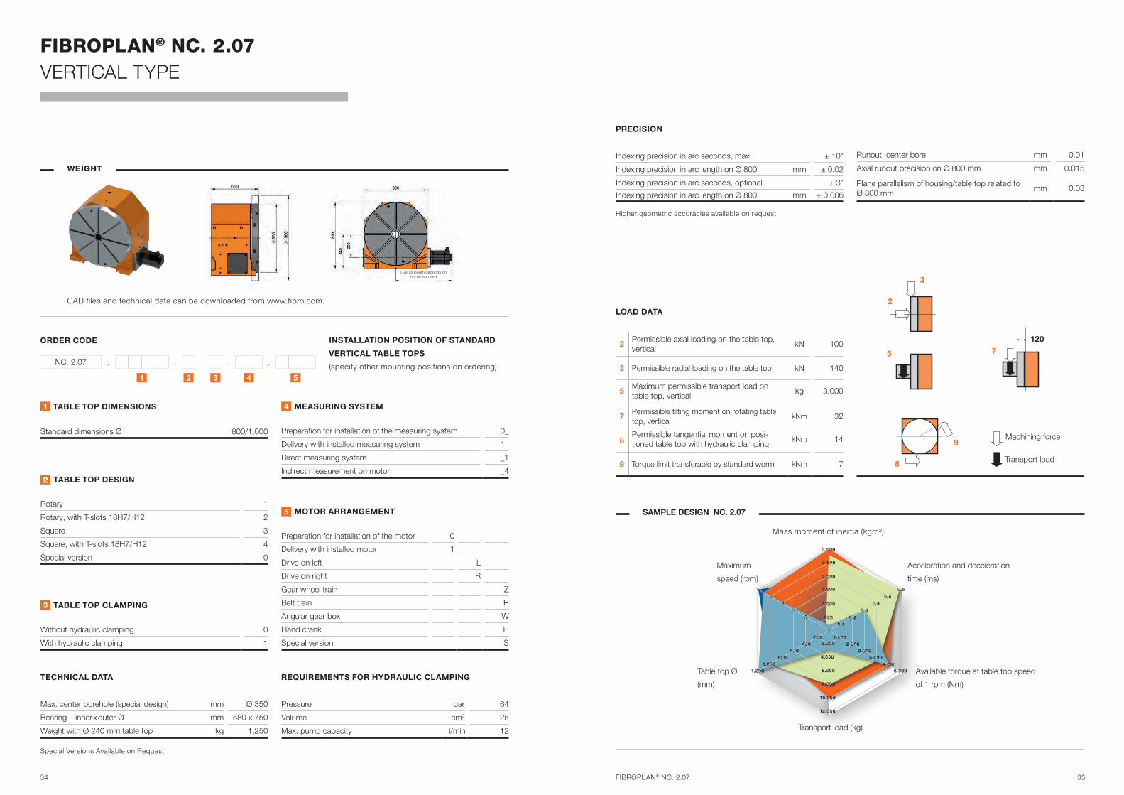
34 35FIBROPLAN® NC. 2.07
3
2
75
9
8
120
WEIGHT
CAD files and technical data can be downloaded from www.fibro.com.
Transport load
Machining force
FIBROPLAN® NC. 2.07 VERTICAL TYPE
1 2 3 4 5
ORDER CODE
NC. 2.07 . . . . .
PRECISION
Indexing precision in arc seconds, max. ± 10”
Indexing precision in arc length on Ø 800 mm ± 0.02
Indexing precision in arc seconds, optional ± 3”
Indexing precision in arc length on Ø 800 mm ± 0.006
Runout: center bore mm 0.01
Axial runout precision on Ø 800 mm mm 0.015
Plane parallelism of housing/table top related to Ø 800 mm
mm 0.03
LOAD DATA
2 Permissible axial loading on the table top, vertical
kN 100
3 Permissible radial loading on the table top kN 140
5 Maximum permissible transport load on table top, vertical
kg 3,000
7 Permissible tilting moment on rotating table top, vertical
kNm 32
8Permissible tangential moment on posi-tioned table top with hydraulic clamping
kNm 14
9 Torque limit transferable by standard worm kNm 7
INSTALLATION POSITION OF STANDARD
VERTICAL TABLE TOPS
(specify other mounting positions on ordering)
SAMPLE DESIGN NC. 2.07
Maximum
speed (rpm)
Transport load (kg)
Acceleration and deceleration
time (ms)
Table top Ø
(mm)
1 TABLE TOP DIMENSIONS
Standard dimensions Ø 800/1,000
2 TABLE TOP DESIGN
Rotary 1
Rotary, with T-slots 18H7/H12 2
Square 3
Square, with T-slots 18H7/H12 4
Special version 0
3 TABLE TOP CLAMPING
Without hydraulic clamping 0
With hydraulic clamping 1
4 MEASURING SYSTEM
Preparation for installation of the measuring system 0_
Delivery with installed measuring system 1_
Direct measuring system _1
Indirect measurement on motor _4
5 MOTOR ARRANGEMENT
Preparation for installation of the motor 0
Delivery with installed motor 1
Drive on left L
Drive on right R
Gear wheel train Z
Belt train R
Angular gear box W
Hand crank H
Special version S
TECHNICAL DATA
Max. center borehole (special design) mm Ø 350
Bearing – inner x outer Ø mm 580 x 750
Weight with Ø 240 mm table top kg 1,250
Pressure bar 64
Volume cm3 25
Max. pump capacity l/min 12
Overall length depends on the motor used
Special Versions Available on Request
REQUIREMENTS FOR HYDRAULIC CLAMPING
Mass moment of inertia (kgm²)
Higher geometric accuracies available on request
Available torque at table top speed
of 1 rpm (Nm)
0
500
1.000
1.500
2.000
2.500
3.000
1.0002.000
3.0004.000
5.0006.000
2.000
4.000
6.000
8.000
10.000
12.000
200400
600800
1.0001.200
0,6
0,5
0,10,2
0,30,4
12
34
56

36 37FIBROPLAN® NC. 2.08
3
2
75
9
8
130
WEIGHT
CAD files and technical data can be downloaded from www.fibro.com.
Transport load
Machining force
FIBROPLAN® NC. 2.08 VERTICAL TYPE
1 2 3 4 5
ORDER CODE
NC. 2.08 . . . . .
PRECISION
Indexing precision in arc seconds, max. ± 10”
Indexing precision in arc length on Ø 1,000 mm ± 0.024
Indexing precision in arc seconds, optional ± 3”
Indexing precision in arc length on Ø 1,000 mm ± 0.007
Runout: center bore mm 0.01
Axial runout precision on Ø 1,000 mm mm 0.02
Plane parallelism of housing/table top related to Ø 1,000 mm
mm 0.04
LOAD DATA
2 Permissible axial loading on the table top, vertical
kN 120
3 Permissible radial loading on the table top kN 250
5 Maximum permissible transport load on table top, vertical
kg 6,000
7 Permissible tilting moment on rotating table top, vertical
kNm 48
8Permissible tangential moment on posi-tioned table top with hydraulic clamping
kNm 25
9 Torque limit transferable by standard worm kNm 14
INSTALLATION POSITION OF STANDARD
VERTICAL TABLE TOPS
(specify other mounting positions on ordering)
SAMPLE DESIGN NC. 2.08
Maximum
speed (rpm)
Transport load (kg)
Acceleration and deceleration
time (ms)
Table top Ø
(mm)
1 TABLE TOP DIMENSIONS
Standard dimensions Ø 1,000/1,250
2 TABLE TOP DESIGN
Rotary 1
Rotary, with T-slots 12H7/H12 2
Square 3
Square, with T-slots 12H7/H12 4
Special version 0
3 TABLE TOP CLAMPING
Without hydraulic clamping 0
With hydraulic clamping 1
4 MEASURING SYSTEM
Preparation for installation of the measuring system 0_
Delivery with installed measuring system 1_
Direct measuring system _1
Indirect measurement on motor _4
5 MOTOR ARRANGEMENT
Preparation for installation of the motor 0
Delivery with installed motor 1
Drive on left L
Drive on right R
Gear wheel train Z
Belt train R
Angular gear box W
Hand crank H
Special version S
TECHNICAL DATA
Max. center borehole (special design) mm Ø 460
Bearing – inner x outer Ø mm 650 x 870
Weight with Ø 240 mm table top kg 2,300
Pressure bar 64
Volume cm3 30
Max. pump capacity l/min 14
Overall length depends on the motor used
Special Versions Available on Request
REQUIREMENTS FOR HYDRAULIC CLAMPING
Mass moment of inertia (kgm²)
Higher geometric accuracies available on request
Available torque at table top speed
of 1 rpm (Nm)
0
12.000
200400
600800
12
34
56
3.500
7.000
10.500
14.000
17.500
21.000
0,9
0,75
0,150,30
0,450,60
2.0004.000
6.0008.000
10.000
1.000
2.000
3.000
4.000
5.000
6.000
1.0001.200

38 39FIBROPLAN® NC. 2.09
3
2
75
9
8
145
WEIGHT
CAD files and technical data can be downloaded from www.fibro.com.
Transport load
Machining force
FIBROPLAN® NC. 2.09 VERTICAL TYPE
1 2 3 4 5
ORDER CODE
NC. 2.09 . . . . .
PRECISION
Indexing precision in arc seconds, max. ± 10”
Indexing precision in arc length on Ø 1,250 mm ± 0.03
Indexing precision in arc seconds, optional ± 3”
Indexing precision in arc length on Ø 1,250 mm ± 0.009
Runout: center bore mm 0.01
Axial runout precision on Ø 1,250 mm mm 0.02
Plane parallelism of housing/table top related to Ø 1,250 mm
mm 0.04
LOAD DATA
2 Permissible axial loading on the table top, vertical
kN 160
3 Permissible radial loading on the table top kN 300
5 Maximum permissible transport load on table top, vertical
kg 8,000
7 Permissible tilting moment on rotating table top, vertical
kNm 60
8Permissible tangential moment on posi-tioned table top with hydraulic clamping
kNm 32
9 Torque limit transferable by standard worm kNm 17
INSTALLATION POSITION OF STANDARD
VERTICAL TABLE TOPS
(specify other mounting positions on ordering)
SAMPLE DESIGN NC. 2.09
Maximum
speed (rpm)
Transport load (kg)
Acceleration and deceleration
time (ms)
Table top Ø
(mm)
1 TABLE TOP DIMENSIONS
Standard dimensions Ø 1,250/1,500
2 TABLE TOP DESIGN
Rotary 1
Rotary, with T-slots 22H7/H12 2
Square 3
Square, with T-slots 22H7/H12 4
Special version 0
3 TABLE TOP CLAMPING
Without hydraulic clamping 0
With hydraulic clamping 1
4 MEASURING SYSTEM
Preparation for installation of the measuring system 0_
Delivery with installed measuring system 1_
Direct measuring system _1
Indirect measurement on motor _4
5 MOTOR ARRANGEMENT
Preparation for installation of the motor 0
Delivery with installed motor 1
Drive on left L
Drive on right R
Gear wheel train Z
Belt train R
Angular gear box W
Hand crank H
Special version S
TECHNICAL DATA
Max. center borehole (special design) mm Ø 600
Bearing – inner x outer Ø mm 850 x 1,095
Weight with Ø 240 mm table top kg 4,000
Pressure bar 64
Volume cm3 40
Max. pump capacity l/min 20
Overall length depends on the motor used
Special Versions Available on Request
REQUIREMENTS FOR HYDRAULIC CLAMPING
Mass moment of inertia (kgm²)
Higher geometric accuracies available on request
Available torque at table top speed
of 1 rpm (Nm)
250
0
500750
1.0001.200
1.500
3.500
7.000
10.500
14.000
17.500
21.000
2
1,8
0,30,6
0,91,2
2.5005.000
7.50010.000
12.50015.000
2.000
4.000
6.000
8.000
10.000
12.000
12
34
56

40 41FIBROPLAN® NC. 2.10
3
2
75
9
8
170
WEIGHT
CAD files and technical data can be downloaded from www.fibro.com.
Transport load
Machining force
FIBROPLAN® NC. 2.10 VERTICAL TYPE
1 2 3 4 5
ORDER CODE
NC. 2.10 . . . . .
PRECISION
Indexing precision in arc seconds, max. ± 10”
Indexing precision in arc length on Ø 1,600 mm ± 0.039
Indexing precision in arc seconds, optional ± 3”
Indexing precision in arc length on Ø 1,600 mm ± 0.012
Runout: center bore mm 0.01
Axial runout precision at Ø 1,600 mm mm 0.025
Plane parallelism of housing/table top related to Ø 1,600 mm
mm 0.05
LOAD DATA
2 Permissible axial loading on the table top, vertical
kN 200
3 Permissible radial loading on the table top kN 400
5 Maximum permissible transport load on table top, vertical
kg 12,000
7 Permissible tilting moment on rotating table top, vertical
kNm 110
8Permissible tangential moment on posi-tioned table top with hydraulic clamping
kNm 40
9 Torque limit transferable by standard worm kNm 24
INSTALLATION POSITION OF STANDARD
VERTICAL TABLE TOPS
(specify other mounting positions on ordering)
SAMPLE DESIGN NC. 2.10
Maximum
speed (rpm)
Transport load (kg)
Acceleration and deceleration
time (ms)
Table top Ø
(mm)
1 TABLE TOP DIMENSIONS
Standard dimensions Ø 1,600
2 TABLE TOP DESIGN
Rotary 1
Rotary, with T-slots 22H7/H12 2
Square 3
Square, with T-slots 22H7/H12 4
Special version 0
3 TABLE TOP CLAMPING
Without hydraulic clamping 0
With hydraulic clamping 1
4 MEASURING SYSTEM
Preparation for installation of the measuring system 0_
Delivery with installed measuring system 1_
Direct measuring system _1
Indirect measurement on motor _4
5 MOTOR ARRANGEMENT
Preparation for installation of the motor 0
Delivery with installed motor 1
Drive on left L
Drive on right R
Gear wheel train Z
Belt train R
Angular gear box W
Hand crank H
Special version S
TECHNICAL DATA
Max. center borehole (special design) mm Ø 750
Bearing – inner x outer Ø mm 1,030 x 1,300
Weight with Ø 240 mm table top kg 5,500
Pressure bar 64
Volume cm3 50
Max. pump capacity l/min 24
Overall length depends on the motor used
Special Versions Available on Request
REQUIREMENTS FOR HYDRAULIC CLAMPING
Mass moment of inertia (kgm²)
Higher geometric accuracies available on request
Available torque at table top speed
of 1 rpm (Nm)
03.000
6.0008.000
11.00014.000
18.000
2.000
4.000
6.000
8.000
10.000
12.000
12
34
56
5.000
15.000
10.000
20.000
25.000
30.000
1,2
1,0
0,20,4
0,60,8
350700
1.0501.400
1.7502.100

42 43
FROM A SINGLE SOURCE
Accessories & special solutions
FIBROPLAN® ROTARY TABLESACCESSORIES
FIBROPLAN® ROTARY TABLESSPECIAL SOLUTIONS
TRUNNION
TAILSTOCKS
ZERO POSITION CLAMPING SYSTEMS LATHE CHUCKS
QUICK-SWITCHING VALVE LOCKS
SLIDE TABLES
TAILORED ROTARY TABLE SOLUTIONS
FOR YOUR APPLICATION
PLANETARY TABLES
ROTARY-LINEAR TABLES STANDALONE ROTARY TABLES
BUILT-IN ROTARY TABLES
ROTARY TABLE/MULTIPLE AXIS COMBINATIONS

BRANCH OFFICE
FIBRO GMBH A COMPANY IN THE GROUP
. LÄPPLE AUTOMOTIVE
. FIBRO
. FIBRO LÄPPLE TECHNOLOGY
. LÄPPLE AUS- UND WEITERBILDUNG
Rotary Table Division
Weidachstraße 41-43
D-74189 Weinsberg
T +49 7134 73-0
F +49 7134 73-218
www.fibro.com
FIBRO ASIA PTE. Ltd.
9 Changi South Street 3, #07-04
Singapore 486361
T +65 65 439963
F +65 65 439962
FIBRO Inc.
Business Area Rotary Tables
139 Harrison Avenue
US-Rockford, IL 61104
T +1 815 2291300
F +1 815 2291303
FIBRO (SHANGHAI) STANDARD
PARTS CO., LTD.
2nd Floor, Building 30, No. 188,
He Dan Road, (Shanghai)
Pilot Free Trade Zone
200131 Shanghai
T +86 021 6083 1589
F +86 021 6083 1599
FIBRO France SARL
Département Plateaux Diviseurs
26 Avenue de l’Europe
FR-67300 Schiltigheim
T +33 390 204041
F +33 388 810829
FIBRO INDIA PRECISION
PRODUCTS PVT. LTD.
Regd. Office & Works
Plot: A-55, Phase II,
Chakan MIDC, Taluka Khed
410501 Pune
T +91 2135 33 88 00
F +91 2135 33 88 88
001
.10
00
0 S
tatu
s: 1
2/2
016


![CNC Milling[1]](https://img.pdfslide.us/doc/110x75/55cf9cd7550346d033ab3f24/cnc-milling1.jpg)