Embed Size (px)
DESCRIPTION
Basics
Citation preview
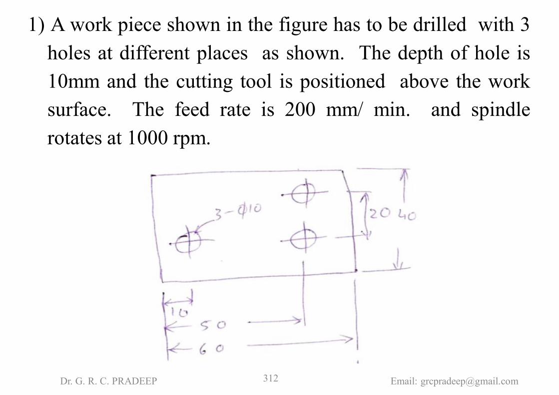
1) A work piece shown in the figure has to be drilled with 3holes at different places as shown. The depth of hole is10mm and the cutting tool is positioned above the worksurface. The feed rate is 200 mm/ min. and spindlerotates at 1000 rpm.
Dr. G. R. C. PRADEEP Email: [email protected]

Dr. G. R. C. PRADEEP Email: [email protected]

N01 G71 G90 G94 F200 S1000 T01 EOBN02 G00 Z2.0 EOBN03 G00 X10.0 Y10.0 EOBN04 G01 Z-10.0 M03EOBN05 G00 Z2.0 EOBN06 G00 X50.0 EOBN07 G01 Z-10.0 EOBN08 G00 Z2.0 EOBN09 G00 Y30.0 EOBN10 G01 Z-10.0 EOBN11 G00 Z2.0 EOBN12 G00 X0.0 Y0.0 M05 EOBN13 M02 EOB
Dr. G. R. C. PRADEEP Email: [email protected]

2) A work piece shown in figure has to be machined alongAB & BC in milling taking depth of cut as 5 mm. Thefeed rate is 200 mm/min, spindle speed is 2000 rpm, cutterdia 10 mm.
Dr. G. R. C. PRADEEP Email: [email protected]

Dr. G. R. C. PRADEEP Email: [email protected]

N05 G71 G90 G94 F200 S2000 T01 EOBN10 G92 X95.0 Y-5.0 Z2.0 EOBN15 G01 Z-5.0 M03 EOBN20 G01 X205.0 EOBN25 G01 Y155.0 EOBN30 G00 Z2.0 EOBN35 G00 X-5.0 Y-5.0 M05 M02 EOB
Dr. G. R. C. PRADEEP Email: [email protected]

3) Prepare a part program for machining a rectangularcontour of 200 mm x 150 mm size from a suitable blankof 5mm thickness. Also a reamed hole of ϕ16 mm has tobe made centrally in the rectangular contour. Take feedand speed arbitrarily.
Ans. Let us assume the following dataT01 – Milling Cutter of Ф10, F=100 mm/min, S =1000 rpmT02 – Drill of Ф15.5, F=80 mm/min, S =800 rpmT03 – Reamer of Ф16, F=50 mm/min, S =500 rpm
Dr. G. R. C. PRADEEP Email: [email protected]

Dr. G. R. C. PRADEEP Email: [email protected]

N001 G71 G90 G94 F100 S1000 T01 EOBN002 G92 X-20.0 Y-20.0 Z 2.0 EOBN003 G78 X-5.0 Y-5.0 Z-5.0 M03 EOBN004 G79 X205.0 EOBN005 G78 Y155.0 EOBN006 G79 X-5.0 EOBN007 G78 Y-5.0 EOBN008 G80 X-20.0 Y-20.0 Z2.0 M05 EOBN009 M06 T02 F80 S800 EOBN010 G81 X100.0 Y75.0 Z-5.0 M03 EOBN011 G80 M05 M06 T03 F50 S500 EOBN012 G81 Z-5.0 M03 EOBN013 G80 M05 M02 EOB
Dr. G. R. C. PRADEEP Email: [email protected]

4. In finish machining of an island on a casting with CNCmilling machine, an end mill of 10mm dia is used. Thecorner points of the island are (0, 0), (0, 30), (50, 30),(50, 0). By applying cutter radius compensation, thetrajectory of the cutter is ____
Ans. Trajectory = Path reqd. to m/c the WP =(-5, -5) (55, -5) (55, 35), (-5, 35) (-5, -5)
Dr. G. R. C. PRADEEP Email: [email protected]

Dr. G. R. C. PRADEEP Email: [email protected]

5) Make a program in Apt for the part shown in the figure.Assume suitable data.
Dr. G. R. C. PRADEEP Email: [email protected]

Dr. G. R. C. PRADEEP Email: [email protected]
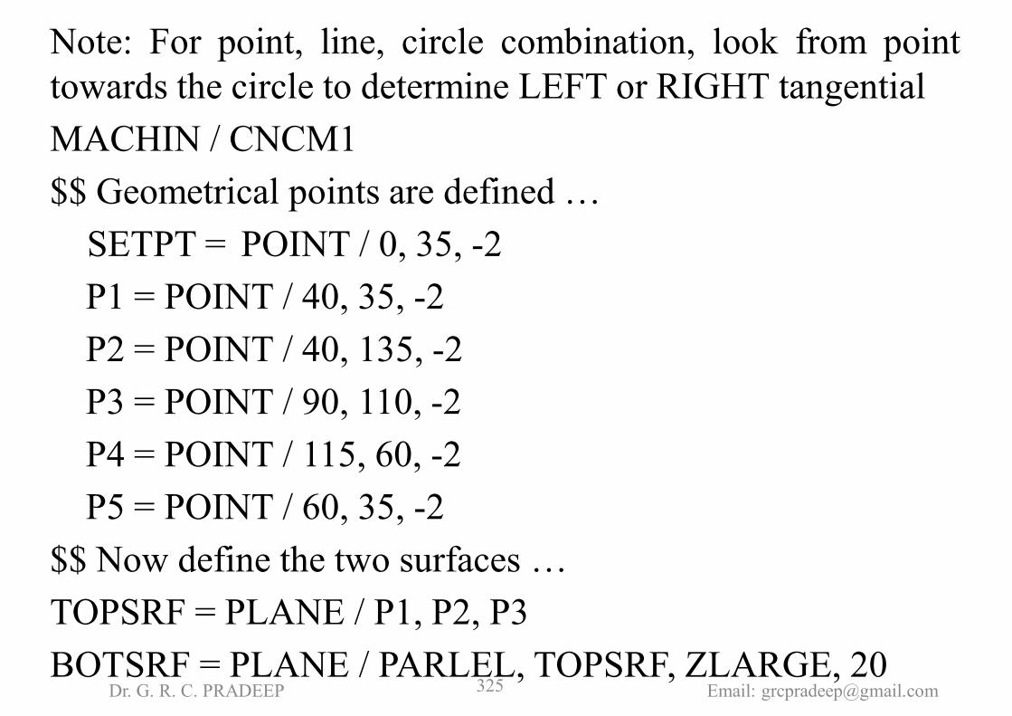
Note: For point, line, circle combination, look from pointtowards the circle to determine LEFT or RIGHT tangentialMACHIN / CNCM1$$ Geometrical points are defined …
SETPT = POINT / 0, 35, -2P1 = POINT / 40, 35, -2P2 = POINT / 40, 135, -2P3 = POINT / 90, 110, -2P4 = POINT / 115, 60, -2P5 = POINT / 60, 35, -2
$$ Now define the two surfaces …TOPSRF = PLANE / P1, P2, P3BOTSRF = PLANE / PARLEL, TOPSRF, ZLARGE, 20
Dr. G. R. C. PRADEEP Email: [email protected]

$$ Define circles and lines ….C1 = CIRCLE / CENTER, P3, RADIUS, 25L1 = LINE / P1, P2L2 = LINE / P2, LEFT, TANTO, C1L3 = LINE / P4, RIGHT, TANTO, C1L4 = LINE / P4, P5L5 = LINE / P5, P1
$$ Now define tool, feed, speed…………LOADTL /1CUTTER / 20SPINDL / 800, CLWFEDRAT / 50, MMPM
Dr. G. R. C. PRADEEP Email: [email protected]

$$ Remaining are motion statements.FROM / SETPT (Define DS, PS & CS respectively)GO / TO, L1, TO, BOTSRF, TO, L5GOLFT/ L1, PAST, L2GORGT / L2, TANTO, C1GOFWD / C1, TANTO, L3GOFWD / L3, PAST, L4GORGT / L4, PAST, L5GORGT / L5, PAST, L1GOTO /SETPTSPINDL / OFFFINIENDDr. G. R. C. PRADEEP Email: [email protected]

6) Make a part program for the part shown using both toolsof mill & drill. Assume plate thickness of 15mm and setpoint at (0,20,0) and Z = 0 at the surface of job.
Dr. G. R. C. PRADEEP Email: [email protected]

Dr. G. R. C. PRADEEP Email: [email protected]

Note:1. For line, two circles combination, look from first circle
towards second circle to determine LEFT or RIGHTtangential
2. For multiple circles in a profile also look from first circletowards other circles to determine LEFT or RIGHTtangential for their line combinations
MACHIN / CNCM1SETPT = POINT / 0, 20, 0P1 = POINT / 20, 20, -2P2 = POINT / 50, 80, -2P3 = POINT / 80, 20, -2
Dr. G. R. C. PRADEEP Email: [email protected]

TOPSRF = PLANE / P1, P2, P3BOTSRF = PLANE / PARLEL, TOPSRF, ZLARGE, 15C1 = CIRCLE / CENTER, P1, RADIUS, 10C2=CIRCLE / CENTER, P2, RAIDUS, 10C3=CIRCLE / CENTER, P3, RADIUS, 10L1=LINE / LEFT, TANTO, C1, LEFT, TANTO, C2L2=LINE / RIGHT, TANTO, C2, LEFT, TANTO, C3L3=LINE / RIGHT, TANTO, C1, RIGHT, TANTO C3LOADTL /1CUTTER /20FEDRAT / 50, MMPMSPINDL / 800, CLWFROM / SETPT
Dr. G. R. C. PRADEEP Email: [email protected]

GO / TO, L1, TO, BOTSRF, TANTO, C1GOLFT / L1, TANTO, C2GOFWD / C2, TANTO, L2GOFWD / L2, TANTO, C3GOFWD / C3, TANTO, L3GOFWD / L3, TANTO, C1GOFWD / C1, TANTO, L1GOTO / SETPTSPINDL / OFFLOADTL /2CUTTER / 10FEDRAT / 80, MMPMSPINDL / 1000, CLW
Dr. G. R. C. PRADEEP Email: [email protected]
GOTO / P1GODOWN / PAST, BOTSRFGOUP / ON, TOPSRFGOTO / P2GODOWN / PAST, BOTSRFGOUP / ON, TOP SRFGOTO / P3GODOWN / PAST, BOTSRFGOUP / ON, TOPSRFGOTO / SETPTSPINDL / OFFFINIEND
Dr. G. R. C. PRADEEP Email: [email protected]

GENERAL RULES FOR APT PROGRAMMING:1. Always set the TOP VIEW in the FIRST QUADRANT.2. Always set the SETPT on the Y-AXIS.3. When coming forward from SETPT always come on to a
LINE. Never come on to a CIRCLE.4. For TANGENTIAL CIRCLES no need of defining the
START POINT and END POINT of the CURVE.5. For INTERSECTING CIRCLES define the
INTERSECTING POINTS.6. The RULES for INTERSECTING CIRCLES are same as
that of LINES. In other words treat the INTERSECTINGCIRCLE as a LINE.
Dr. G. R. C. PRADEEP Email: [email protected]

7) Make a program in APT for the part shown in the figure.Assume suitable data.
Dr. G. R. C. PRADEEP Email: [email protected]

Define all points assuming suitable dataTOPSRF = PLANE / P1,P2,P3BOTSRF = PLANE / PARLEL, TOPSRF, ZLARGE,8C1 = CIRCLE / CENTER, P2, RADIUS, 30C2 = CIRCLE / CENTER, P5, RADIUS, 40L1= LINE / P1, LEFT, TANTO, C1L2 = LINE / P3, RIGHT, TANTO, C1L3 = LINE / P3, P4L4 = LINE / P6, P1LOADTL / 1CUTTER / 10SPINDL / 1000, CLWFEDRAT / 80, MMPM
Dr. G. R. C. PRADEEP Email: [email protected]

FROM / SETPTGO / TO, L1, TO, BOTSRF, TO, L4GOLFT / L1, TANTO, C1GOFWD / C1, TANTO, L2GOFWD / L2, PAST, L3GORGT / L3, PAST, INTOF, L3, C2GORGT / C2, PAST, INTOF, C2, L4GORGT / L4, PAST, L1GOTO/SETPTSPINDL/OFFFINIEND
Dr. G. R. C. PRADEEP Email: [email protected]
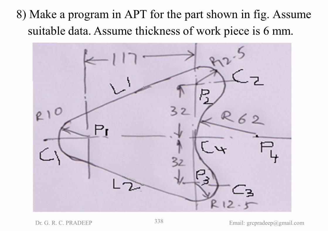
8) Make a program in APT for the part shown in fig. Assumesuitable data. Assume thickness of work piece is 6 mm.
Dr. G. R. C. PRADEEP Email: [email protected]

Define all points assuming suitable dataTOPSRF = PLANE / P1, P2, P3BOTSRF = PLANE / PARLEL, TOPSRF, ZLARGE, 8C1 = CIRCLE / CENTER, P1, RADIUS, 10C2 = CIRCLE / CENTER, P2, RADIUS, 12.5C3 = CIRCLE / CENTER, P3, RADIUS, 12.5C4 = CIRCLE / CENTER, P4, RADIUS, 62L1 = LINE / LEFT, TANTO, C1, LEFT, TANTO, C2L2 = LINE / RIGHT, TANTO, C1, RIGHT, TANTO, C3LOADTL/ 1CUTTER / 10SPINDL / 1000, CLWFEDRAT / 80, MMPM
Dr. G. R. C. PRADEEP Email: [email protected]

FROM / SETPTGO / TO, L1, TO, BOTSRF, TANTO, C1GOLFT / L1, TANTO, C2GOFWD / C2, TANTO, C4GOFWD / C4, TANTO, C3GOFWD / C3, TANTO, L2GOFWD / L2, TANTO, C1GOFWD / C1, TANTO, L1GOTO / SETPTSPINDL / OFFFINIEND
Dr. G. R. C. PRADEEP Email: [email protected]