Embed Size (px)
Citation preview
TC-32B Title
2003/4/21 1 eTCOMNCPRT1.doc
TC-32B
NC PROGRAMMINGMANUAL
Please read this manual carefully before starting operation.

TC-32B Title
2003/3/20 2 eTCOMNCPRT1.doc
1
This manual describes the NC-Programming of the TC-32B.The tapping centre is able to perform drilling, tapping, and facing.We shall not bear any responsibility for accidents caused by user's special handling or handlingdeviating from the generally recognized safe operation.
The relation between the manuals is as follows.- OPERATION MANUALThis manual describes the operations of the machine.
- INSTALLATION MANUALThis manual describes the installation of the machine.
- PROGRAMMING MANUALThis manual describes the programming of the machine.
Keep this manual for future reference.Please include this manual when reselling this product.When this manual or labels are lost or damaged, please replace them (charged) from your nearestagency.
This manual is printed by using paper obtained from farmed trees.

TC-32B Title
2003/4/21 3 eTCOMNCPRT1.doc
INTRODUCTION
Congratulations on your purchase of the Brother CNCtapping center. Correct usage of the machine is of most importance to assure theexpected machine capabilities and functions as well as operator's safety. Read thisManual thoroughly before starting operation.
* All rights reserved: No part of this manual may be reproduced, stored in a retrieval system,or transmitted in any form without prior permission of the manufacturer.
* The contents of this Manual are subject to change without notice.* This manual are complied with utmost care. If you encounter any question or doubt,
please contact your local dealer.© Copyrigt 2004 BROTHER INDUSTRIES,LTD. Machinery & Solution Company. Machine Tools Field. ALL RIGHTS RESERVED.
TC-32B Title
2003/3/20 4 eTCOMNCPRT1.doc
1
HOW TO USE THE MANUAL
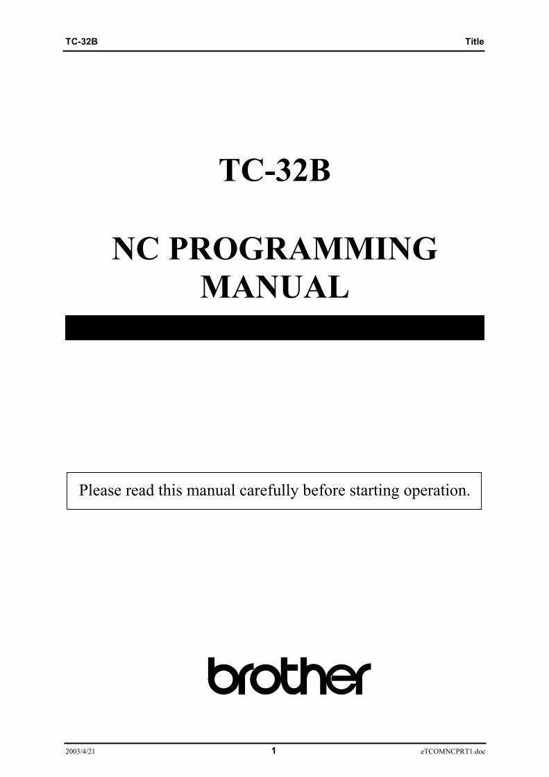
This Instruction Manual consists of the following elements:(1) General description Is an outline of the description given in the section.(2) Alarm Is a alert given against a danger which may cause serious
damage or death to human being or may damage the machine.The hazards are explained in this order:degree of danger,subject of danger,expected damage,preventive measure,
(3) Operation procedure Is a procedure of activating a function.(4) Screen Is given to describe important points of a procedure given.
NOTE: This screen is only a representation of the informationdisplayed on the actual screen and therefore differssomewhat from the actual screenlayout and screen fonts.
(5) Illustration Is a sketch, figure, view, etc. indicating dimensions, position or zone, givenin the points where it is necessary to provide complementary information to the textdescription.
1 - 31 - 2
1.3 Precautions of first
WARNING
Dropping a heavy object ontoyour foot may fracture your footbones.When lifting heavy objects,wear safety shoes.
1.3.1Before starting operation
Before starting operation careful to read bellow.
(1)Turn off the main power breaker handle on the control box door. Never touch the primary side power source or the terminal of the main power breaker, as these have high voltage applied.(2)Put up a signboard which says' Under Maintenance(3)Never allow people to approach the machine, particularly moving areas.(4)Do not place any unnecessary object around the machine.(5)Wear a helmet and safety shoes.
(5) Illustration (4) Screen
(2) Alarm (3) Operation procedure(1) General description
TC-32B Contents
2004/01/19 1 eTCOMNCPRC.doc
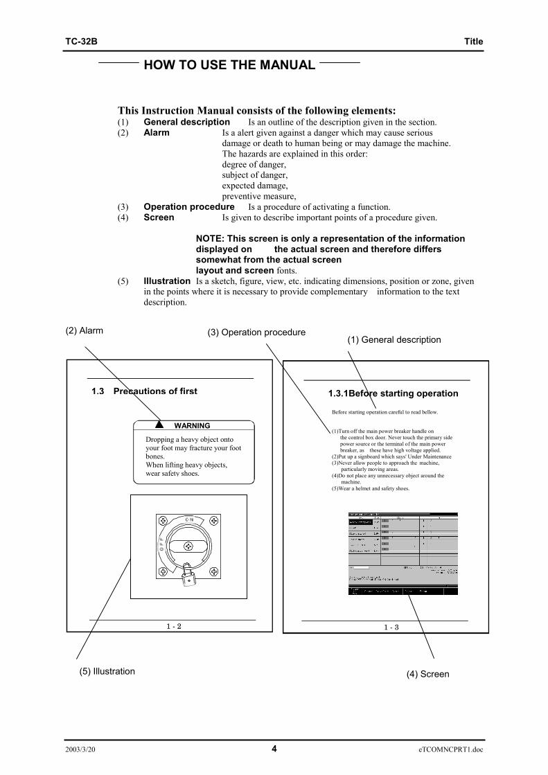
Chapter 1 Program Composition-------------------------------- 1-11.1 Types and composition of program ------------------------------------1-21.2 Composition of block -------------------------------------------------------1-21.3 Composition of word --------------------------------------------------------1-31.4 Numerical values ----------------------------------------------------------1-31.5 Sequence number ---------------------------------------------------------------1-41.6 Optional block skip -------------------------------------------------------------1-41.7 Control out/in function---------------------------------------------------------1-4
Chapter 2 Coordinate Command -------------------------------- 2-12.1 Coordinate system and coordinate value-------------------------------2-22.2 Machine zero point and machine coordinate system---------------2-32.3 Working coordinate system--------------------------------------------------2-3
Chapter 3 Preparation Function --------------------------------- 3-13.1 Outline of G code ----------------------------------------------------------------3-23.2 Positioning (G00) ------------------------------------------------------------3-93.3 Linear interpolation (G01) ----------------------------------------------------3-10
3.3.1 Chamfering to desired angle and cornering C ----------------------------------------------3-113.4 Circular/helical interpolation (G02, G03) --------------------------------3-14
3.4.1 Circular interpolation ---------------------------------------------------------------------------3-14 3.4.1.1 Circular interpolation ----------------------------------------------------------------------3-14 3.4.1.2 XZ Circular interpolation -----------------------------------------------------------------3-15 3.4.1.3 YZ Circular interpolation -----------------------------------------------------------------3-163.4.2 Helical interpolation-----------------------------------------------------------------------------3-203.4.3 Spiral interpolation (G02, G03) ---------------------------------------------------------------3-213.4.4 Conical interpolation (G02, G03) -------------------------------------------------------------3-233.4.5 Cutter compensation procedure for spiral interpolation and conical interpolation (G02, G03)----------------------------------------------------------------------------------------3-26
3.5 Circle Cutting (G12, G13) -----------------------------------------------------3-273.6 Plane Selection (G17, G18, G19) -------------------------------------------3-283.7 Dwell (G04)-------------------------------------------------------------------------3-293.8 Exact stop check (G09, G61, G64) -----------------------------------------3-293.9 Programmable data input (G10) --------------------------------------------3-313.10 Soft limit ----------------------------------------------------------------------------3-34
3.10.1 Stroke --------------------------------------------------------------------------------------------3-343.10.2 Stroke limit --------------------------------------------------------------------------------------3-343.10.3 Programmable stroke limit (G22) -----------------------------------------------------------3-35
3.11 Return to the reference point (G28) ---------------------------------------3-363.12 Return from the reference point(G29) ------------------------------------3-373.13 Return to the 2nd/3rd/4th reference point (G30)----------------------3-373.14 Selection of machine coordinate system (G53)-----------------------3-373.15 Selection of working coordinate system (G54~G59)----------------3-383.16 Additional working coordinate system selection (G54.1) ---------3-383.17 Scaling (G50, G51) --------------------------------------------------------------3-393.18 Programmable Mirror Image (G50.1, G51.1)----------------------------3-433.19 Rotational transformation function (G68,G69) ------------------------3-463.20 Coordinate rotation using measured results(G168)-----------------3-483.21 Absolute command and incremental command (G90, G91)------3-483.22 Change of workpiece coordinate system(G92) -----------------------3-503.23 Skip function (G31,G131,G132)---------------------------------------------3-523.24 Continuous skip function (G31) --------------------------------------------3-533.25 Change of tap twisting direction(G133,G134) -------------------------3-533.26 High speed peck drilling cycle (G173)) ----------------------------------3-54
TC-32B Contents
2004/01/23 2 eTCOMNCPRC.doc
3.27 Peck drilling cycle (G183) ----------------------------------------------------3-553.28 Local coordinate system function (G52) --------------------------------3-563.29 Single direction positioning function(G60)-----------------------------3-573.30 G code priority--------------------------------------------------------------------3-58
Chapter 4 Preparation Function (tool offset function) ---- 4-14.1 Tool Dia Offset(G40,G41,G42)-----------------------------------------------4-2
4.1.1 Tool dia offset function-------------------------------------------------------------------------4-2 4.1.1.1 Tool dia fine compensation---------------------------------------------------------------4-24.1.2 Cancel Mode -------------------------------------------------------------------------------------4-34.1.3 Start -up -------------------------------------------------------------------------------------------4-4 4.1.3.1 Inside cutting -------------------------------------------------------------------------------4-4 4.1.3.2 Outside cutting (90° ≤ θ < 180°)---------------------------------------------------------4-5 4.1.3.3 Outside cutting (θ < 90°)------------------------------------------------------------------4-64.1.4 Offset Mode-------------------------------------------------------------------------------------4-7 4.1.4.1 Inside cutting (180° ≤ θ) ------------------------------------------------------------------4-7 4.1.4.2 Outside cutting (90° ≤ θ < 180°)---------------------------------------------------------4-9 4.1.4.3 Outside cutting (θ < 90°)------------------------------------------------------------------4-10 4.1.4.4 Exceptional case ----------------------------------------------------------------------------4-114.1.5 Offset Cancel -------------------------------------------------------------------------------------4-12 4.1.5.1 Inside cutting (180° ≤ θ) ------------------------------------------------------------------4-12 4.1.5.2 Outside cutting (90° ≤ θ < 180°)---------------------------------------------------------4-12 4.1.5.3 Outside cutting (θ < 90°)------------------------------------------------------------------4-144.1.6 G40 single command----------------------------------------------------------------------------4-154.1.7 Change of offset direction in offset mode ---------------------------------------------------4-164.1.8 Change of offset direction in offset mode --------------------------------------------------4-17 4.1.8.1 When there is a cross point --------------------------------------------------------------4-17 4.1.8.2 When there is no cross point -------------------------------------------------------------4-18 4.1.8.3 When offset path becomes more than a circle -----------------------------------------4-194.1.9 G cord command for tool dia offset in offset mode----------------------------------------4-204.1.10 Notes on tool dia offset -------------------------------------------------------------------------4-214.1.11 Override function related to tool dia offset--------------------------------------------------4-29 4.1.11.1 Automatic corner override --------------------------------------------------------------4-29 4.1.11.2 Override of the inside circular cutting-------------------------------------------------4-304.2 Tool length offset (G43,G44,G49) -----------------------------------4-314.2.1 Tool length fine offset --------------------------------------------------------------------------4-31
Chapter 5 Preparation Function (canned cycle) ------------ 5-15.1 List of canned cycle function -----------------------------------------------5-25.2 Basic motions in canned cycle ---------------------------------------------5-35.3 General description of canned cycle ------------------------------------5-4
5.3.1 Command related to canned cycle motions------------------------------------------------5-45.3.2 Setting of data in absolute / incremental command --------------------------------------5-45.3.3 Types of return point (G98,G99) ------------------------------------------------------------5-55.3.4 Canned cycle motion conditions-------------------------------------------------------------5-55.3.5 Machining data of canned cycle -------------------------------------------------------------5-65.3.6 Repeat number of canned cycle--------------------------------------------------------------5-7
5.4 Details of Canned Cycle-------------------------------------------------------5-85.4.1 High-speed peck drilling cycle (G73) ------------------------------------------------------5-85.4.2 Reverse tapping cycle (G74) -----------------------------------------------------------------5-95.4.3 Fine boring cycle (G76)-----------------------------------------------------------------------5-105.4.4 Tapping cycle (G77)---------------------------------------------------------------------------5-115.4.5 Reverse tapping cycle (Synchro mode) (G78) --------------------------------------------5-125.4.6 Drilling cycle (G81,G82) ---------------------------------------------------------------------5-135.4.7 Peck drilling cycle (G83) ---------------------------------------------------------------------5-155.4.8 Tapping cycle (G84)---------------------------------------------------------------------------5-165.4.9 Boring cycle (G85,G89) ----------------------------------------------------------------------5-175.4.10 Boring cycle (G86)-----------------------------------------------------------------------------5-185.4.11 Back boring cycle (G87) ----------------------------------------------------------------------5-20
TC-32B Contents
2004/01/19 3 eTCOMNCPRC.doc
5.4.12 End mill tap cycle (G177) --------------------------------------------------------------------5-215.4.13 End mill tap cycle (G178) --------------------------------------------------------------------5-225.4.14 Double drilling cycle (G181,G182) ---------------------------------------------------------5-235.4.15 Double boring cycle (G185,G189) ----------------------------------------------------------5-245.4.16 Double boring cycle (G186)------------------------------------------------------------------5-255.4.17 Canned cycle of reducing step ---------------------------------------------------------------5-265.4.18 Canned cycle cancel (G80) -------------------------------------------------------------------5-325.4.19 Notes on canned cycle ------------------------------------------------------------------------5-33
5.5 Canned cycle for tool change (non-stop ATC)(G100)---------------5-34
Chapter 6 Preparation Function (coordinate calculation)6-16.1 List of coordinate calculation function ----------------------------------6-26.2 Coordinate calculation parameter -----------------------------------------6-26.3 Details of coordinate calculation function------------------------------6-3
6.3.1 Bolt hole circle ---------------------------------------------------------------------------------6-36.3.2 Linear (Angle) ----------------------------------------------------------------------------------6-46.3.3 Linear (X,Y) ------------------------------------------------------------------------------------6-46.3.4 Grid --------------------------------------------------------------------------------------------6-5
6.4 Usage of coordinate calculation function-------------------------------6-6
Chapter 7 Macro------------------------------------------------------- 7-17.1 What is a Macro? ----------------------------------------------------------------7-27.2 Variable Function----------------------------------------------------------------7-3
7.2.1 Outline of variable function ------------------------------------------------------------------7-37.2.2 Expression of variable-------------------------------------------------------------------------7-37.2.3 Undefined variable-----------------------------------------------------------------------------7-47.2.4 Types of variables------------------------------------------------------------------------------7-57.2.5 Variable display and setting ------------------------------------------------------------------7-67.2.6 System variable---------------------------------------------------------------------------------7-7
7.3 Calculation Function ---------------------------------------------------------7-127.3.1 Calculation type --------------------------------------------------------------------------------7-127.3.2 Calculation order -------------------------------------------------------------------------------7-127.3.3 Precautions for calculation ------------------------------------------------------------------- 7-13
7.4 Control Function---------------------------------------------------------------7-14 7.4.1 GOTO statement (unconditional branch)------------------------------------------------7-14 7.4.2 IF statement (conditional branch)-----------------------------------------------------------7-14 7.4.3 WHILE statement (repetition) ---------------------------------------------------------------7-15 7.4.4 Precautions for control function-------------------------------------------------------------7-167.5 Call Function--------------------------------------------------------------------7-18 7.5.1 Simple call function ---------------------------------------------------------------------------7-19 7.5.2 Modal call function----------------------------------------------------------------------------7-20 7.5.3 Macro call argument --------------------------------------------------------------------------7-21 7.5.4 Difference between G65 and M98----------------------------------------------------------7-23 7.5.5 Multiple nesting call---------------------------------------------------------------------------7-24
Chapter 8 Automatic work measurement--------------------- 8-18.1 Before automatic work measurement ------------------------------------8-48.2 Setting of data on automatic work measurement --------------------8-48.3 Operation of automatic work measurement----------------------------8-9
8.3.1 Corner --------------------------------------------------------------------------------------------8-98.3.2 Parallel -------------------------------------------------------------------------------------------8-138.3.3 Circle ---------------------------------------------------------------------------------------------8-168.3.4 Z level --------------------------------------------------------------------------------------------8-208.3.5 Positioning to the measurement position---------------------------------------------------8-20
8.4 Handling of measured results-----------------------------------------------8-218.4.1 Display of the measured results--------------------------------------------------------------8-218.4.2 Reflection of measured results on the workpiece coordinate system------------------8-22
8.5 Lock key operations ------------------------------------------------------------8-24

TC-32B Contents
2004/01/23 4 eTCOMNCPRC.doc
Chapter 9 High Accuracy Mode A--------------------------------- 9-19.1 Outline-------------------------------------------------------------------------------9-29.2 Usage --------------------------------------------------------------------------------9-3
9.2.1 User parameter setting ------------------------------------------------------------------------9-39.2.2 User parameter description -------------------------------------------------------------------9-49.2.3 Usage in a program ----------------------------------------------------------------------------9-59.2.4 Conditions available ---------------------------------------------------------------------------9-69.2.5 Conditions where high accuracy mode A is released ------------------------------------9-6
9.3 Restrictions------------------------------------------------------------------------9-79.3.1 Functions available ----------------------------------------------------------------------------9-79.3.2 Additional axis travel command -------------------------------------------------------------9-7
9.4 Effective Functions -------------------------------------------------------------9-89.4.1 Automatic corner deceleration function ----------------------------------------------------9-89.4.2 Automatic arc deceleration function -------------------------------------------------------9-99.4.3 Automatic curve approximation deceleration ---------------------------------------------9-10
Chapter 10 Subprogram function --------------------------------- 10-110.1 Making subprogram ------------------------------------------------------------10-210.2 Simple call ----------------------------------------------------------------------10-310.3 Return No. designation from sub program-----------------------------10-4
10.3.1 Command by sub program--------------------------------------------------------------------10-410.3.2 Command by main program------------------------------------------------------------------10-4
Chapter 11 Feed function-------------------------------------------- 11-1
Chapter 12 S,T,M function------------------------------------------- 12-112.1 S function --------------------------------------------------------------------------12-212.2 T function --------------------------------------------------------------------------12-2
12.2.1 Commanded by tool No. ----------------------------------------------------------------------12-212.2.2 Commanding by pot No. (magazine No.) --------------------------------------------------12-212.2.3 Commanded by group No.--------------------------------------------------------------------12-2
12.3 M function--------------------------------------------------------------------------12-312.3.1 Program stop (M00) ---------------------------------------------------------------------------12-712.3.2 Optional stop (M01) ---------------------------------------------------------------------------12-712.3.3 End of program (M02, M30) -----------------------------------------------------------------12-712.3.4 Commands on the spindle (M03, M04, M05, M19, M111)-----------------------------12-7 12.3.4.1 Spindle orientation to desired angle (M19) ---------------------------------------12-712.3.5 M signal level output (M400~M409) -------------------------------------------------------12-712.3.6 Tool change (M06)-----------------------------------------------------------------------------12-812.3.7 Workpiece counter specification (M211~M214) -----------------------------------------12-1212.3.8 Workpiece counter cancel (M221~M224) -------------------------------------------------12-12 12.3.8.1 Tool life counter -----------------------------------------------------------------------12-1212.3.9 Automatic corner deceleration (M232, M233) ------------------------------------------12-1212.3.10 Tool breakage detection (M120 and M121)----------------------------------------------12-1212.3.11 Tool breakage detection (M200 and M201)----------------------------------------------12-1212.3.12 Tap time constant selection (M241 to 250) ----------------------------------------------12-1312.3.13 Pallet related M codes (M410, M411, M430, and M431) -----------------------------12-1312.3.14 Unclamping and clamping C axis (M430 and M431) ----------------------------------12-1312.3.15 Unclamping and clamping B axis (M440 and M441) ----------------------------------12-1312.3.16 Unclamping and clamping A axis (M442 and M443) ----------------------------------12-1312.3.17 One-shot output (M450, M451, M455, and M456)-------------------------------------12-1312.3.18 Waiting until response is given (M460 to M469) ---------------------------------------12-1412.3.19 Magazine rotate speed (M435 to M437)--------------------------------------------------12-1412.3.20 Magazine rotate to tool setting position (M501 to M599) -----------------------------12-1412.3.21 Positioning finished check distance (M270 to M279)----------------------------------12-14
TC-32B Contents
2004/01/19 5 eTCOMNCPRC.doc
Chapter 13 Option------------------------------------------------------ 13-113.1 Programming precautions when using rotation axis (index table) -----------------------------------------------------------------------13-2

TC-32B Contents
2004/01/23 6 eTCOMNCPRC.doc
(This page is a blank.)

TC-32B Quick index
2004/01/16 1 eTCOMPRIN.doc
88
7
6
5
4
3
2
1
9
10
11
12
13
Chpt. 1 PROGRAM COMPOSITION
Chpt. 2 COORDINATE COMMAND
Chpt. 3 PREPARATION FUNCTION
Chpt. 4
Chpt. 5 PREPARATION FUNCTION (CANNED CYCLE)
Chpt. 6
Chpt. 7 MACRO
Chpt. 8 AUTOMATIC WORK MEASUREMENT
Chpt. 9 HIGH ACCURACY MODE
Chpt.10 SUBPROGRAM FUNCTION
Chpt.11 FEED FUNCTION
Chpt.12 S, T, M FUNCTION
Chpt.13 OPTION
PREPARATION FUNCTION (TOOL OFFSET FUNCTION)
PREPARATION FUNCTION (COORDINATE CALCULATION))

Quick index TC-32B
2003/04/14 2 TCOMCOOP8-2
(This page is a blank.)
TC-32B Chapter 1 Program Composition
2004/01/22 1 - 1 eTCOMNCPR1-1.doc
1
CHAPTER 1
PROGRAM COMPOSITION
1.1 Types and composition of program1.2 Composition of block1.3 Composition of word1.4 Numerical values1.5 Sequence number1.6 Optional block skip1.7 Control out/in function

Chapter 1 Program Composition TC-32B
2004/01/22 1 - 2 eTCOMNCPR1-1.doc
1
1.1 Types and Composition of ProgramThe program is divided into the main program and the subprogram.
(1) Main programThe main program is for machining one workpiece. While the main program is in use, asubprogram can be called to use the program more efficiently.Command M02 (or M30) to finish the main program.
Main programN0001 G92X100;
N0002 G00Z30:::M02;
(2) SubprogramA subprogram is used by calling it from the main program or other subprograms. Command M99 to finish the subprogram.
SubprogramN0100 G91X10;:::M99;
1.2 Composition of BlockThe program is composed of several commands. One command is called a block. A block iscomposed of one or more words. One block is discriminated from another block by an end ofblock code (EOB).This manual expresses the end of block code by the symbol ";".
⋅⋅⋅ ; N0001 G92X100 ; ⋅⋅⋅ ; M02 ;
(Note 1) The end of block codeISO code : [LF] 0A(hexadecimal)EIA code : [CR] 80(hexadecimal)
(Note 2) One block has maximum 128 characters.
Block Block

TC-32B Chapter 1 Program Composition
2004/01/22 1 - 3 eTCOMNCPR1-1.doc
1
1.3 Compositiom of WordA word is composed of an address and some digit of figures as shown below. (Algebraic sign + or - may added before a numerical value.)
(Note 1) The address uses one of the alphabetical letters.(Note 2) The address "O" can not be used except for comments.
1.4 Numerical Values(1) Decimal point programmingNumerical values can be input in the following two ways and set by the userparameter (Switch 1).
Command type 1 (Standard)Programmed command Commanded axis Actual amount (mm) Actual amount (inch)
Feed axis 1mm 1 inch1
Rotation axis 1 deg 1 deg
Rotation axis 1 mm 1 inch1.Rotation axis 1 deg 1 deg
Command type 2 (Minimum)Programmed command Commanded axis Actual amount (mm) Actual amount (inch)
Feed axis 0.001 mm 0.0001 inch1
Rotation axis 0.001 deg 0.001 deg
Rotation axis 1 mm 1 inch1.Rotation axis 1 deg 1 deg
(Note) User parameter : Refer to Instruction manual.
(2) Programmable range of addressThe maximum number of digits is 9.The digits less than the minimum range are ignored.
X
Address numerical value
Word
-1000
Chapter 1 Program Composition TC-32B
2004/01/22 1 - 4 eTCOMNCPR1-1.doc
1
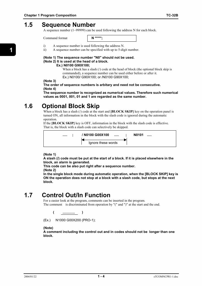
1.5 Sequence NumberA sequence number (1~99999) can be used following the address N for each block.
Command format N *****;
i) A sequence number is used following the address N.ii) A sequence number can be specified with up to 5-digit number.
(Note 1) The sequence number "N0" should not be used.(Note 2) It is used at the head of a block.
Ex.) N0100 G90X100;When a block has a slash (/) code at the head of block (the optional block skip iscommanded), a sequence number can be used either before or after it.Ex.) N0100/ G90X100; or /N0100 G90X100;
(Note 3)The order of sequence numbers is arbitary and need not be consecutive.(Note 4)The sequence number is recognized as numerical values. Therefore such numericalvalues as 0001, 001, 01 and 1 are regarded as the same number.
1.6 Optional Block SkipWhen a block has a slash (/) code at the start and [BLOCK SKIP] key on the operation panel isturned ON, all information in the block with the slash code is ignored during the automaticoperation.If the [BLOCK SKIP] key is OFF, information in the block with the slash code is effective.That is, the block with a slash code can selectively be skipped.
..... ; / N0100 G00X100 ..... ; N0101 .....
Ignore these words
(Note 1)A slash (/) code must be put at the start of a block. If it is placed elsewhere in theblock, an alarm is generated.This code can be also put right after a sequence number.(Note 2)In the single block mode during automatic operation, when the [BLOCK SKIP] key isON the operation does not stop at a block with a slash code, but stops at the nextblock.
1.7 Control Out/In FunctionFor a easier look at the program, comments can be inserted in the program.The comment is discriminated from operation by "(" and ")" at the start and the end.
( ............. )
(Ex.) N1000 G00X200 (PRO-1);
(Note)A comment including the control out and in codes should not be longer than oneblock.

TC-32B Chapter2 Coordinate Command
2004/01/22 2 - 1 eTCOMNCPR2-1.doc
2
CHAPTER 2
COORDINATE COMMAND
2.1 Coordinate system and coordinate value2.2 Machine zero point and machine coordinate system2.3 Working coordinate system
Chapter2 Coordinate Command TC-32B
2004/01/22 2 - 2 eTCOMNCPR2-1.doc
2
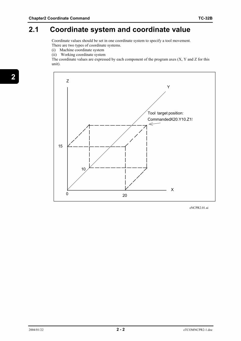
2.1 Coordinate system and coordinate valueCoordinate values should be set in one coordinate system to specify a tool movement.There are two types of coordinate systems.(i) Machine coordinate system(ii) Working coordinate systemThe coordinate values are expressed by each component of the program axes (X, Y and Z for thisunit).
eNCPR2.01.ai
Tool target position:CommandedX20.Y10.Z15
Z
20
10
0
15
Y
X

TC-32B Chapter2 Coordinate Command
2004/01/22 2 - 3 eTCOMNCPR2-1.doc
2
2.2 Machine Zero Point and Machine CoordinateSystem(1) Machine zero pointThe machine zero point is the reference point on the machine.
(2) Machine coordinate systemThe coordinate systen with the machine zero point as its reference point is called the machinecoordinate system. Each machine has its own coordinate system.
eNCPR2.02.ai
2.3 Working Coordinate SystemThe working coordinate system is used to specify a tool motion for each workpiece.A coordinate system previously set in the "Data Bank" is once selected, programming afterwardcan be easily done by specifying that coordinate system.Each coordinate system is set by using an offset amount from the machine zero point to theworking zero position.(Note) Data Bank : Refer to Instruction manual.
Y axisstroke
X axis strokeMachine zero point
(0,0,0)
-X
-Y
Table

Chapter2 Coordinate Command TC-32B
2004/01/22 2 - 4 eTCOMNCPR2-1.doc
2
( This page is a blank.)

TC-32B Chapter 3 Preparation Function
2004/01/22 3 - 1 eTCOMNCPR3.doc
3CHAPTER 3
PREPARATION FUNCTION
3.1 Outline of G code3.2 Positioning (G00)3.3 Linear interpolation (G01)3.4 Circular/helical interpolation (G02, G03)3.5 Circle cutting (G12, G13)3.6 Plane selection (G17, G18, G19)3.7 Dwell (G04)3.8 Exact stop check (G09, G61, G64)3.9 Programmable data input (G10)3.10 Soft limit3.11 Return to the reference point (G28)3.12 Return from the reference point (G29)3.13 Return to the 2nd/3rd/4th reference point (G30)3.14 Selection of machine coordinate system (G53)3.15 Selection of working coordinate system (G54~G59)3.16 Additional working coordinate system selection
(G54.1)3.17 Scaling (G50, G51)3.18 Programmable mirror image (G50.1, G51.1)3.19 Coordinate rotation function (G68, G69)3.20 Coordinate rotation using measured results (G168)3.21 Absolute command and incremental command
(G90, G91)3.22 Change of working coordinate system (G92)3.23 Skip function (G31, G131, G132)3.24 Continuous skip function (G31)3.25 Change of tap twisting direction (G133, G134)3.26 High speed peck drilling cycle (G173)

Chapter 3 Preparation Function TC-32B
2004/01/22 3 - 2 eTCOMNCPR3.doc
3
3.27 Peck drilling cycle (G183)3.28 Local coordinate system function (G52)3.29 Single direction positioning function (G60)3.30 G code priority
TC-32B Chapter 3 Preparation Function
2004/01/22 3 - 3 eTCOMNCPR3.doc
3
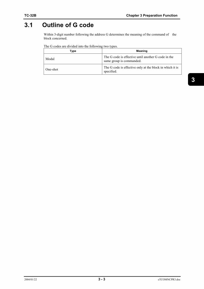
3.1 Outline of G codeWithin 3-digit number following the address G determines the meaning of the command of theblock concerned.
The G codes are divided into the following two types.Type Meaning
Modal The G code is effective until another G code in thesame group is commanded.
One-shot The G code is effective only at the block in which it isspecified.
Chapter 3 Preparation Function TC-32B
2004/01/22 3 - 4 eTCOMNCPR3.doc
3
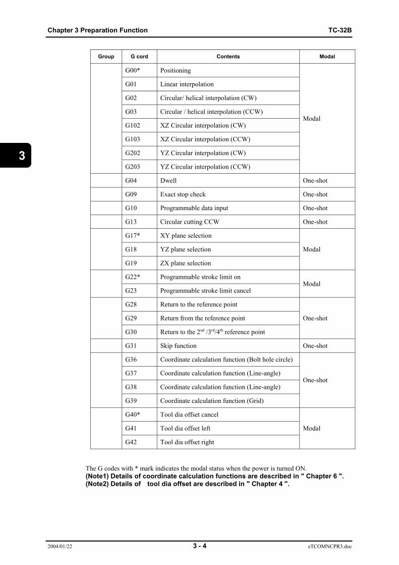
Group G cord Contents Modal
G00* Positioning
G01 Linear interpolation
G02 Circular/ helical interpolation (CW)
G03 Circular / helical interpolation (CCW)
G102 XZ Circular interpolation (CW)
G103 XZ Circular interpolation (CCW)
G202 YZ Circular interpolation (CW)
G203 YZ Circular interpolation (CCW)
Modal
G04 Dwell One-shot
G09 Exact stop check One-shot
G10 Programmable data input One-shot
G13 Circular cutting CCW One-shot
G17* XY plane selection
G18 YZ plane selection
G19 ZX plane selection
Modal
G22* Programmable stroke limit on
G23 Programmable stroke limit cancelModal
G28 Return to the reference point
G29 Return from the reference point
G30 Return to the 2nd /3rd/4th reference point
One-shot
G31 Skip function One-shot
G36 Coordinate calculation function (Bolt hole circle)
G37 Coordinate calculation function (Line-angle)
G38 Coordinate calculation function (Line-angle)
G39 Coordinate calculation function (Grid)
One-shot
G40* Tool dia offset cancel
G41 Tool dia offset left
G42 Tool dia offset right
Modal
The G codes with * mark indicates the modal status when the power is turned ON.(Note1) Details of coordinate calculation functions are described in " Chapter 6 ".(Note2) Details of tool dia offset are described in " Chapter 4 ".

TC-32B Chapter 3 Preparation Function
2004/01/22 3 - 5 eTCOMNCPR3.doc
3
Group G cord Contents Modal
G43 Tool length offset +
G44 Tool length offset -
G49* Tool length offset cancel
Modal
G50* Scaling cancel
G51 ScalingModal
G50.1 Mirror image cancel
G51.1 Mirror imageModal
G52 Local coordinate system
G53 Machine coordinate system selectionOne-shot
G54* Working coordinate system selection 1
G55 Working coordinate system selection 2
G56 Working coordinate system selection 3
G57 Working coordinate system selection 4
G58 Working coordinate system selection 5
G59 Working coordinate system selection 6
G54.1 Extended working coordinate system selection
Modal
G60 Single direction positioning One-shot
G61 Exact stop mode
G64* Cutting modeModal
G65 Macro call One-shot
G66 Macro modal call
G67* Cancel macro modal callModal
G68 Coordinate rotation function
G69* Coordinate rotation function cancel
G168 Coordinate rotation using measured results
Modal

Chapter 3 Preparation Function TC-32B
2004/01/22 3 - 6 eTCOMNCPR3.doc
3
Group G cord Contents Modal
G90* Absolute command
G91 Incremental commandModal
G92 Working coordinate system setting One-shot
G94 Feed rate per minute
G98* Return to the initial point level
G99 Return to the R point levelModal
G73 Canned cycle (High-speed peck drilling cycle)
G74 Canned cycle (Reverse tapping cycle)
G76 Canned cycle (Fine boring cycle)
G77 Canned cycle (Tapping cycle, synchro mode)
G78 Canned cycle (Reverse tapping cycle, synchromode)
G80* Canned cycle cancel
G81 Canned cycle (Drill, spot drilling cycle)
G82 Canned cycle (Drill, spot drilling cycle)
G83 Canned cycle (Peck drilling cycle)
G84 Canned cycle (Tapping cycle)
G85 Canned cycle (Boring cycle)
G86 Canned cycle (Boring cycle)
G87 Canned cycle (Back boring cycle)
G89 Canned cycle (Boring cycle)
Modal
TC-32B Chapter 3 Preparation Function
2004/01/22 3 - 7 eTCOMNCPR3.doc
3
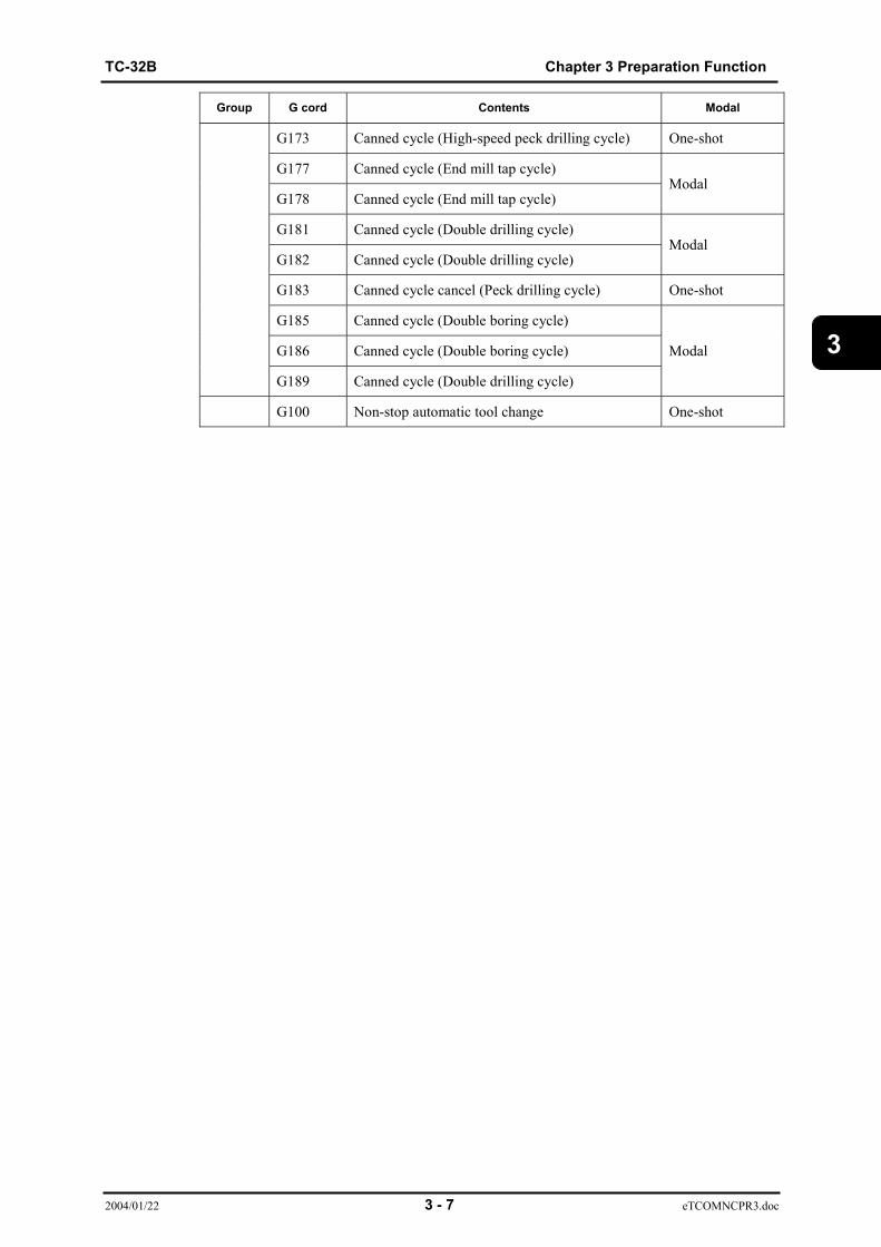
Group G cord Contents Modal
G173 Canned cycle (High-speed peck drilling cycle) One-shot
G177 Canned cycle (End mill tap cycle)
G178 Canned cycle (End mill tap cycle)Modal
G181 Canned cycle (Double drilling cycle)
G182 Canned cycle (Double drilling cycle)Modal
G183 Canned cycle cancel (Peck drilling cycle) One-shot
G185 Canned cycle (Double boring cycle)
G186 Canned cycle (Double boring cycle)
G189 Canned cycle (Double drilling cycle)
Modal
G100 Non-stop automatic tool change One-shot
Chapter 3 Preparation Function TC-32B
2004/01/22 3 - 8 eTCOMNCPR3.doc
3
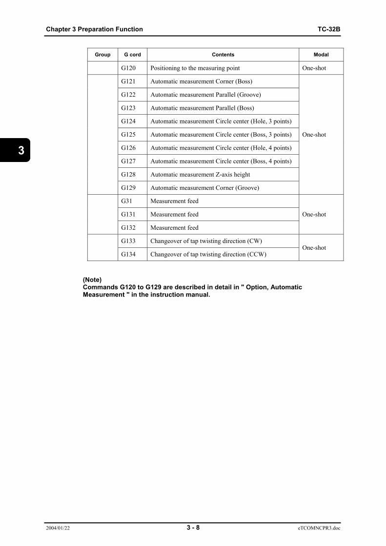
Group G cord Contents Modal
G120 Positioning to the measuring point One-shot
G121 Automatic measurement Corner (Boss)
G122 Automatic measurement Parallel (Groove)
G123 Automatic measurement Parallel (Boss)
G124 Automatic measurement Circle center (Hole, 3 points)
G125 Automatic measurement Circle center (Boss, 3 points)
G126 Automatic measurement Circle center (Hole, 4 points)
G127 Automatic measurement Circle center (Boss, 4 points)
G128 Automatic measurement Z-axis height
G129 Automatic measurement Corner (Groove)
One-shot
G31 Measurement feed
G131 Measurement feed
G132 Measurement feed
One-shot
G133 Changeover of tap twisting direction (CW)
G134 Changeover of tap twisting direction (CCW)One-shot
(Note)Commands G120 to G129 are described in detail in " Option, AutomaticMeasurement " in the instruction manual.
TC-32B Chapter 3 Preparation Function
2004/01/22 3 - 9 eTCOMNCPR3.doc
3
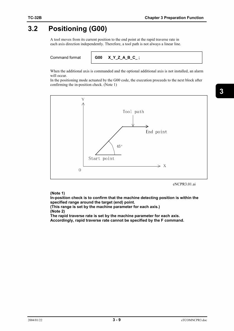
3.2 Positioning (G00)A tool moves from its current position to the end point at the rapid traverse rate ineach axis direction independently. Therefore, a tool path is not always a linear line.
Command format G00 X_Y_Z_A_B_C_ ;
When the additional axis is commanded and the optional additional axis is not installed, an alarmwill occur.In the positioning mode actuated by the G00 code, the execution proceeds to the next block afterconfirming the in-position check. (Note 1)
eNCPR3.01.ai
(Note 1)In-position check is to confirm that the machine detecting position is within thespecified range around the target (end) point.(This range is set by the machine parameter for each axis.)(Note 2)The rapid traverse rate is set by the machine parameter for each axis.Accordingly, rapid traverse rate cannot be specified by the F command.

Chapter 3 Preparation Function TC-32B
2004/01/22 3 - 10 eTCOMNCPR3.doc
3
3.3 Linear interpolation (G01)Linear interpolation moves a tool linearly from the current position to the target position at thespecified feedrate.
Command format G01 X_Y_F_ ;
Up to X,Y,X and one additional axis can be controlled simultaneously.When the additional axis is commanded and the optional additional axis is not installed, an alarmwill occur.
The feedrate is commanded by the address F. Once the feedrate is commanded, it is effective untilanother value is specified.When the X, Y, and Z axes are commanded, the feedrate is determined by the value entered to mm/ min.When the additional axis is commanded, the feedrate is determined by the value entered to ー/min.
eNCPR3.2.ai
(Note 1) Feedrate along each axis is as follows:When "G01 G91 Xα Yβ Ff ;" is programmed:
αFeedrate along X axis: Fx= ─── • f L
βFeedrate along Y axis: Fy= ─── • f L
( L = α2 + β2 )
Endpoint
Startpoint

TC-32B Chapter 3 Preparation Function
2004/01/22 3 - 11 eTCOMNCPR3.doc
3
(Note2)The example below shows linear interpolation of linear axis α and rotation axis β.
When "G01 G91 Xα Bβ Ff ;" is programmed:
α2+β2
Time taken for B-axis movement: Tb= f β
Feedrate along B axis: Fb= Tb α
Feedrate along X axis: Fx= · f L
3.3.1 Chamfering to desired angle and cornering CChamfering to the desired angle or rounding can be performed between interpolation commands.
Chamfering
Command format G01 X_Y_, C_ ;
C: Distance from virtual corner to the chamfer start point and sendpoint.
eNCPR3.03.ai
(1) The corner chamfering command block and subsequent block must contain theinterpolation command (G01-G03).When the subsequent block does not contain an interpolation or movement command, analarm will occur.
(2) The inserted block belongs to the corner chamfering command block. Thus, if the feed ratediffers from the corner chamfering command block and the subsequent block , the insertedblock moves at the feed rate of the cornerchamfering command block. Further, the program does not stop before the inserted blockoccurs even during single block operation. (It stops after the inserted block occurs.)
(3) Tool diameter compensation applies to the configuration after corner chamfering isperformed.
Y
X
c
c
Virtualcornerintersection
Chamfer start point
Chamfer end poi
Chapter 3 Preparation Function TC-32B
2004/01/22 3 - 12 eTCOMNCPR3.doc
3
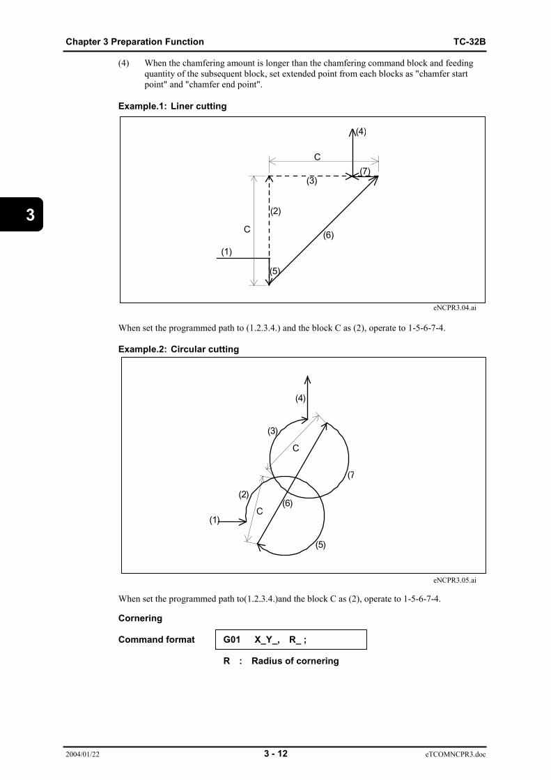
(4) When the chamfering amount is longer than the chamfering command block and feedingquantity of the subsequent block, set extended point from each blocks as "chamfer startpoint" and "chamfer end point".
Example.1: Liner cutting
eNCPR3.04.ai
When set the programmed path to (1.2.3.4.) and the block C as (2), operate to 1-5-6-7-4.
Example.2: Circular cutting
eNCPR3.05.ai
When set the programmed path to(1.2.3.4.)and the block C as (2), operate to 1-5-6-7-4.
Cornering
Command format G01 X_Y_, R_ ;
R : Radius of cornering
C
C
(1)
(5)
(2)
(3)
(4)
(7)
(6)
C
C
(2)
(1)
(5)
(7
(6)
(3)
(4)
TC-32B Chapter 3 Preparation Function
2004/01/22 3 - 13 eTCOMNCPR3.doc
3
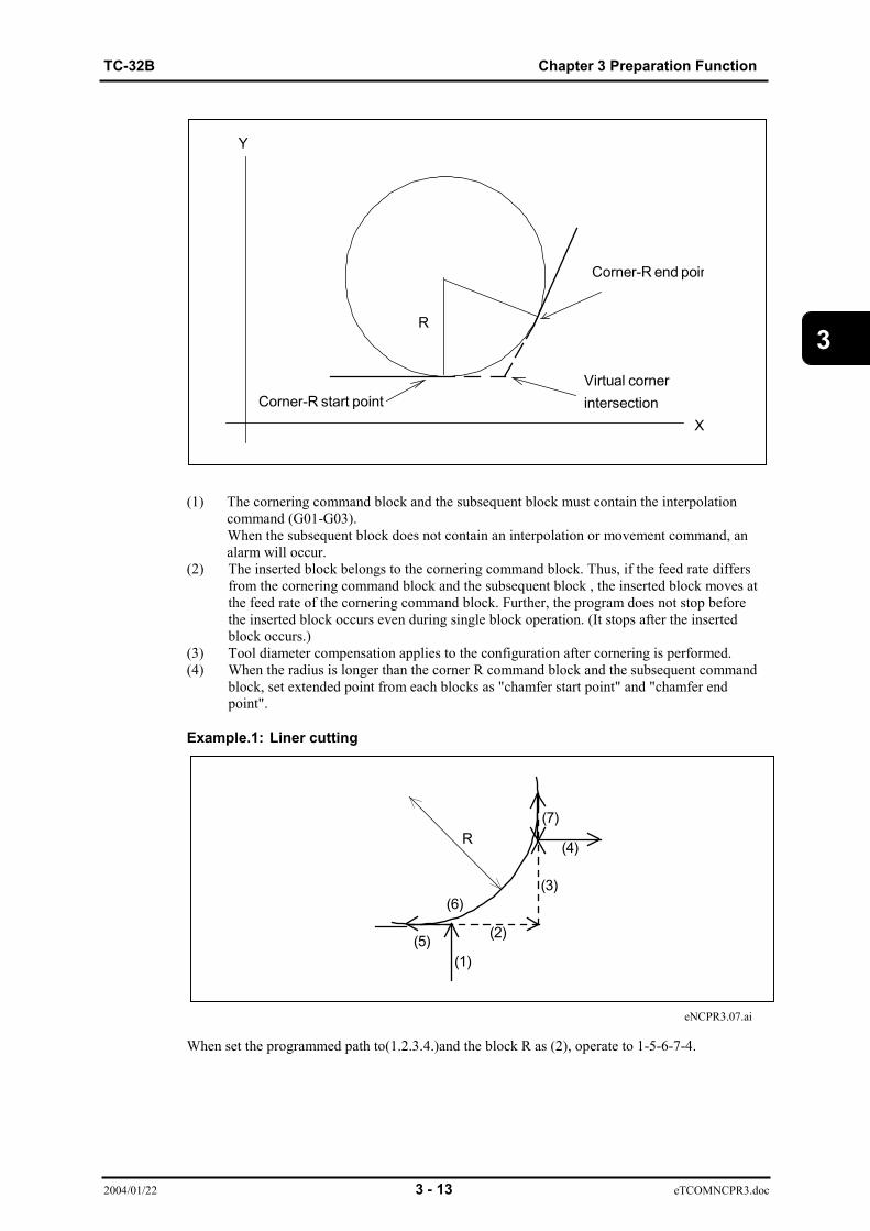
(1) The cornering command block and the subsequent block must contain the interpolationcommand (G01-G03).When the subsequent block does not contain an interpolation or movement command, analarm will occur.
(2) The inserted block belongs to the cornering command block. Thus, if the feed rate differsfrom the cornering command block and the subsequent block , the inserted block moves atthe feed rate of the cornering command block. Further, the program does not stop beforethe inserted block occurs even during single block operation. (It stops after the insertedblock occurs.)
(3) Tool diameter compensation applies to the configuration after cornering is performed.(4) When the radius is longer than the corner R command block and the subsequent command
block, set extended point from each blocks as "chamfer start point" and "chamfer endpoint".
Example.1: Liner cutting
eNCPR3.07.ai
When set the programmed path to(1.2.3.4.)and the block R as (2), operate to 1-5-6-7-4.
X
Corner-R end poin
Virtual cornerintersectionCorner-R start point
R
Y
R
(1)(5) (2)
(3)
(4)
(7)
(6)
Chapter 3 Preparation Function TC-32B
2004/01/22 3 - 14 eTCOMNCPR3.doc
3
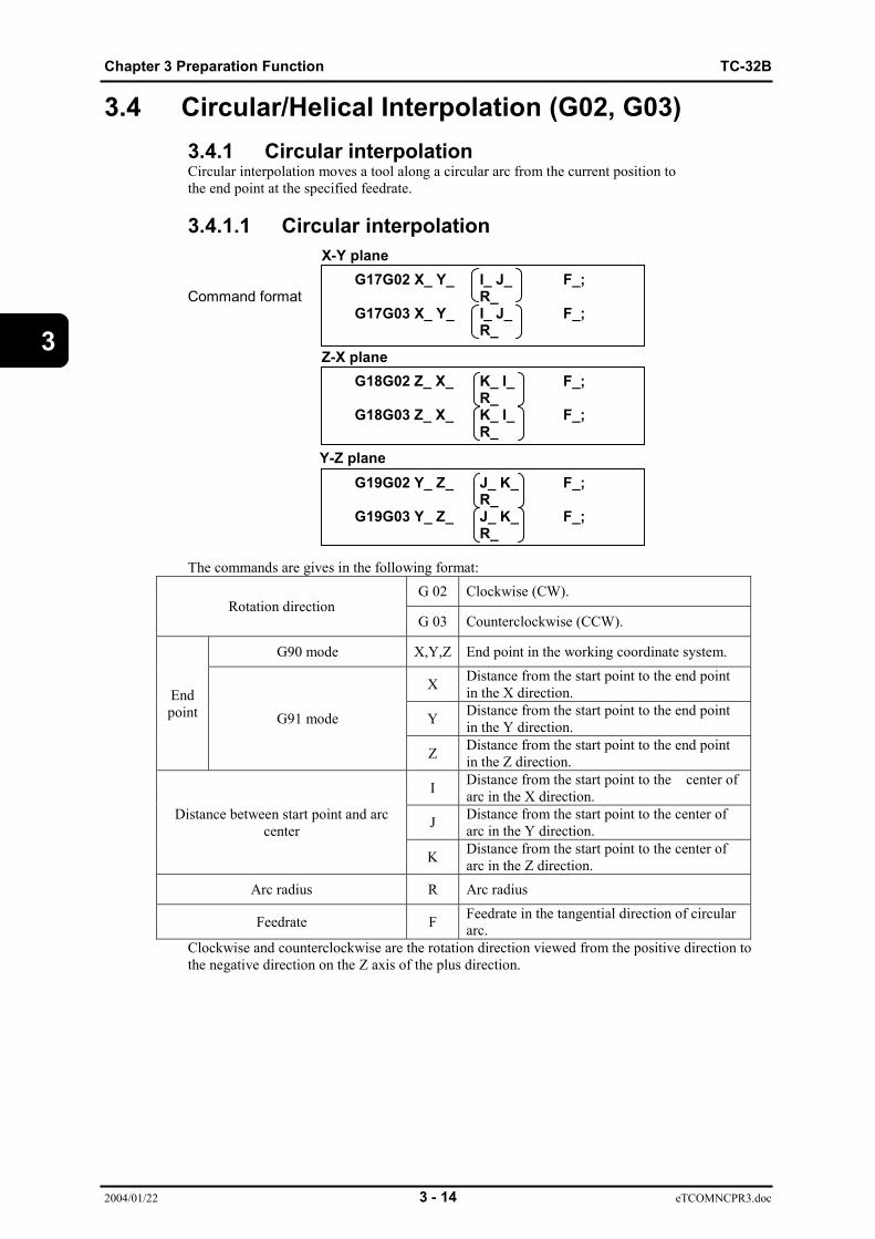
3.4 Circular/Helical Interpolation (G02, G03)3.4.1 Circular interpolationCircular interpolation moves a tool along a circular arc from the current position tothe end point at the specified feedrate.
3.4.1.1 Circular interpolation
G17G02 X_ Y_ I_ J_ F_;Command format R_
G17G03 X_ Y_ I_ J_ F_;R_
G18G02 Z_ X_ K_ I_ F_;R_
G18G03 Z_ X_ K_ I_ F_;R_
G19G02 Y_ Z_ J_ K_ F_; R_
G19G03 Y_ Z_ J_ K_ F_;R_
The commands are gives in the following format:G 02 Clockwise (CW).
Rotation directionG 03 Counterclockwise (CCW).
G90 mode X,Y,Z End point in the working coordinate system.
X Distance from the start point to the end pointin the X direction.
Y Distance from the start point to the end pointin the Y direction.
Endpoint G91 mode
Z Distance from the start point to the end pointin the Z direction.
I Distance from the start point to the center ofarc in the X direction.
J Distance from the start point to the center ofarc in the Y direction.
Distance between start point and arccenter
K Distance from the start point to the center ofarc in the Z direction.
Arc radius R Arc radius
Feedrate F Feedrate in the tangential direction of circulararc.
Clockwise and counterclockwise are the rotation direction viewed from the positive direction tothe negative direction on the Z axis of the plus direction.
X-Y plane
Z-X plane
Y-Z plane

TC-32B Chapter 3 Preparation Function
2004/01/22 3 - 15 eTCOMNCPR3.doc
3
3.4.1.2 XZ Circular interpolation
G102 X_ Y_ I_ J F_;Command format
G103 R_
The commands are given in the following format:G 102 Clockwise (CW).
Rotation directionG103 Counterclockwise (CCW).
G90 mode X,Y End point in the working coordinate system.
X Distance from the start point to the end pointin the X direction.
Endpoint G91 mode
Y Distance from the start point to the end pointin the Y direction.
I Distance from the start point to the center ofarc in the X direction.Distance between start point and arc
center J Distance from the start point to the center ofarc in the Y direction.
Arc radius R Arc radius
Feedrate F Feedrate in the tangential direction of circulararc.
Clockwise and counterclockwise are the rotation direction viewed from the positive direction tothe negative direction on the Y axis of the X-Z plane.
(Note 1)In contrast to the XY arc case, an error occurs when the diameter compensationcommand (G41, G42) or coordinate rotation command (G68, G168) is used, and themachine stops operation.

Chapter 3 Preparation Function TC-32B
2004/01/22 3 - 16 eTCOMNCPR3.doc
3
3.4.1.3 XZ Circular interpolation
G202 X_ Y_ I_ J F_;Command format
G203 R_
The commands are given in the following format:G202 Clockwise (CW).
Rotation directionG203 Counterclockwise (CCW).
G90 mode X,Y End point in the working coordinate system.
X Distance from the start point to the end pointin the X direction.
Endpoint G91 mode
Y Distance from the start point to the end pointin the Y direction.
I Distance from the start point to the center ofarc in the X direction.Distance between start point and arc
center J Distance from the start point to the center ofarc in the Y direction.
Arc radius R Arc radius
Feedrate F Feedrate in the tangential direction of circulararc.
Clockwise and counterclockwise are the rotation direction viewed from the positivedirection to the negative direction on the X axis of the Y-Z plane.
(Note 1)In contrast to the XY arc case, an error occurs when the diameter compensationcommand (G41, G42) or coordinate rotation command (G68, G168) is used, and themachine stops operation.

TC-32B Chapter 3 Preparation Function
2004/01/22 3 - 17 eTCOMNCPR3.doc
3
The end point of the circular arc takes either the absolute value or the incrementalvalue according to G90 or G91. The incremental value commands the distance from the circulararc start point to the end point.The circular arc center is commanded by both I,J and K according to X,Y and Z axes. I,J and Kform a vector component when viewed from the circular arc start point to the center.It is commanded by the incremental value regardless of G90 or G91.
eNCPR3.08.ai
Instead of commanding I, J and K to specify the center of arc, the radius of arc can be used.There are two types of circular arcs (one is less than 180° and the other is more than 180°).When commanding a circular arc of more than 180°, put the algebraic mark "-" before the valuefor the radius.
eNCPR3.09.ai
(1) G02XxYyR(2) G02XxYyR
Absolute command;G90G03XxYyIiJjFf;
Incremental commanG91G03XxYyIiJjFf;

Chapter 3 Preparation Function TC-32B
2004/01/22 3 - 18 eTCOMNCPR3.doc
3
eNCPR3.10.aiAbsolute command;G03X-60. Y-10. I-50. J-20. F1000 ;Incremental command;G03X-30. Y30. I-50. J-20. F1000 ;
eNCPR3.11.ai(1) G02X-70. Y-50. R25. F1000 ;(2) G02X-70. Y-50. R-25. F1000 ;
(Note 1) When either I, J or K is omitted, it is regarded zero.(Note 2) The circular arc, when its radius is zero, cannot be commanded.(Note 3) When both X,Y and Z are omitted, the end point and the start point are
regarded identical, and:i) 360°arc (full circle) is assumed to be commanded when the arc center
is programmed using the address I,J and K.ii) When the address R is used, an alarm occurred.
(Note 4) The address R and "I, J and K" cannot be commanded simultaneously.(Note 5) When the end point is not on the arc specified by start point and arc
radius, the tool moves as shown below.

TC-32B Chapter 3 Preparation Function
2004/01/22 3 - 19 eTCOMNCPR3.doc
3eNCPR3.15.ai
eNCPR3.14.ai(Note 6) If the ending radius is extremely larger than that of the starting radius,
an alarm will occur.(Note 7) The G36~G39 codes cannot be commanded in the circular arc mode.
Transition of radius

Chapter 3 Preparation Function TC-32B
2004/01/22 3 - 20 eTCOMNCPR3.doc
3
3.4.2 Helical interpolationPutting the other than selected plane axis command in the circular arc block permits a helicalcutting.
Command format
X-Y plane:G17G02 X_Y_Z_ I_ J_ F_;
R_G17G03 X_Y_Z_ I_ J_ F_;
R_Z-Y plane:G18G02 Z_X_Y_ K_I_ F_;
R_G18G03 Z_X_Y_ K_I_ F_;
R_Y-Z plane:G19G02 Y_Z_X_ J_K_ F_;
R_G19G03 Y_Z_X_ J_K_ F_;
R_
The F code commands the feedrate in the circular interpolation axis..
If the value of F is larger than the MAXIMUM CUTTING SPEED or the FEEDRATE SPEED setby the machine parameter, an alarm is generated.
The feedrate in the other than selected plane axis is determined by the values of "feedrate" in thecircular interpolation axis, "end point X", "end point Y" and "end point Z". It can be calculated asfollows: 180 × LFZ = × F
π × R × θ
F: Command speed (X, Y axes)R: Radius (Start point, center)θ: AngleFz: Other than selected plane of feeedrate speed.L: Other than selected plane of feeed distance.
Ex.) Setting following values: F=500 (mm/min), R=10 (mm), θ=360 (°), L=2 (mm)
Fz = (180×2×500)/(π×10×360) 15.9 (mm/min)
If the other than selected plane axis feedrate is larger than the MAXIMUM CUTTING SPEED orFEEDRATE SPEED set by the machine parameter , an alarm is generated.
When tool dia offset command is given, an offset is applied to the selected plane.
. .=

TC-32B Chapter 3 Preparation Function
2004/01/22 3 - 21 eTCOMNCPR3.doc
3
3.4.3 Spiral interpolation (G02, G03)An increment or decrement per rotation is specified for the circular interpolation command toperform spiral interpolation.
Command formatX-Y plane:{G17}G02X_Y_I_J_Q_L_F_;{G17}G03X_Y_I_J_Q_L_F_;Z-Y plane:{G18}G02Z_X_K_I_Q_L_F_;{G18}G03Z_X_K_I_Q_L_F_;Y-Z plane:{G19}G02Y_Z_J_K_Q_L_F_;{G19}G03Y_Z_J_K_Q_L_F_;
G02 : Clockwise cutting directionG03 : Counterclockwise cutting directionXYZ : Coordinates of end pointL : Number of rotations (positive value, decimal numbers are rounded up to the nearest
whole number). Add a decimal point, rounded off.Example: Set "L6" for five and 1/4 rotations (5.25 rotations).
Q : Increment or decrement in radius per rotationSetting a positive value increases the radius for each rotation.Setting a negative value decreases the radius for each rotation.
IJK : Vector (distance and direction) from the start point to the center (the same ascircular interpolation)
F : Cutting speed
(Note)Either L (number of rotations) or Q (increment/decrement in radius) can be omitted.If there is a discrepancy between "L" and "Q" when used together, "Q" is used.
Y
X
20
20
100
- -50
Start point (0,100)
End point (X,Y)(0,-50.)Distance to the center (I,J)(0,-100.) Increment/decrement in radius Q –20.0 No. of rotations L 3
Absolute command1) G90G02X0.Y-50.I0J-100.Q-20.;
2) G90G02X0.Y-50.I0J-100.L4;Incremental command
1) G91G02X0Y-150.I0J-100.Q-20.;
2) G91G02X0Y-150.I0J-100.L4
Setting either 1) or 2) is acceptable.

Chapter 3 Preparation Function TC-32B
2004/01/22 3 - 22 eTCOMNCPR3.doc
3
Cutter compensation can be performed only in offset mode. An alarm will occur when this isattempted in startup or cancel mode.
The setting for [Cutter compensation] is applied relative to the start point and target point specifiedin the program during cutter compensation.
An alarm will occur when the programmed conical interpolation tool path or the tool path aftercutter compensation intersects or makes contact with the spiral center.
An alarm will occur when the spiral defined that over the circle radius fudge factor limit point bythe increment or decrement in radius per rotation does not match the end point.
An alarm will occur when corner CR is specified in the block immediately before a block thatperforms spiral interpolation.
Automatic corner override is not possible for the blocks immediately before and after a block thatperforms spiral interpolation.
Corner CR cannot be specified for spiral interpolation.
An alarm will occur when the radius is zero (0) or less (including negative values) as a result ofsetting an increment/decrement in the radius per rotation and the number of rotations.
An alarm will occur when the radius is specified using command "R."
An alarm will occur when the increment or decrement in radius is zero (0).
An alarm will occur when setting value of selected flat as below. (1) Start point radius = End point radius (2) Start point = Center (3) End point = Center
Not commanded when mirror image is effective.Not commanded when scaling image is effective.
When a cutter compensation cancel command is included in the block immediately after a blockthat performs spiral interpolation and cutter compensation, the end point of the spiral interpolationwill be the position given by the vertical vector from the end point of spiral interpolation.
An in-position check is performed between the blocks immediately before and after a block thatperforms spiral interpolation.
TC-32B Chapter 3 Preparation Function
2004/01/22 3 - 23 eTCOMNCPR3.doc
3
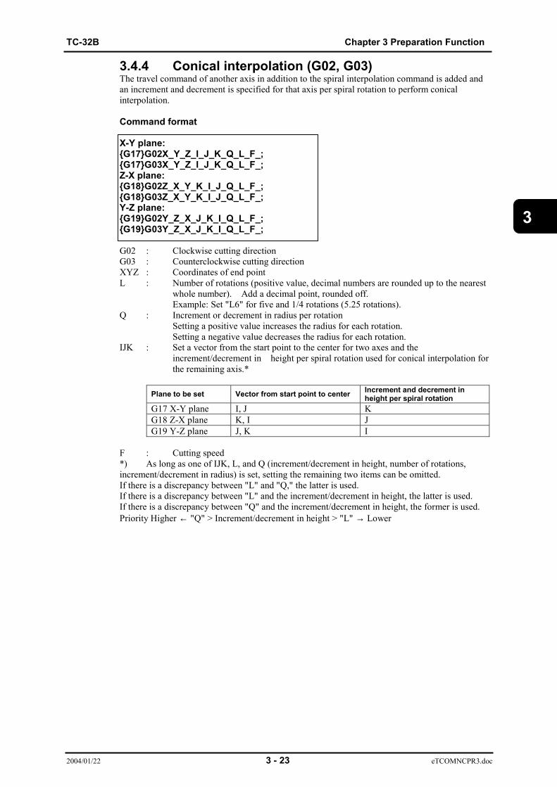
3.4.4 Conical interpolation (G02, G03)The travel command of another axis in addition to the spiral interpolation command is added andan increment and decrement is specified for that axis per spiral rotation to perform conicalinterpolation.
Command format
X-Y plane:{G17}G02X_Y_Z_I_J_K_Q_L_F_;{G17}G03X_Y_Z_I_J_K_Q_L_F_;Z-X plane:{G18}G02Z_X_Y_K_I_J_Q_L_F_;{G18}G03Z_X_Y_K_I_J_Q_L_F_;Y-Z plane:{G19}G02Y_Z_X_J_K_I_Q_L_F_;{G19}G03Y_Z_X_J_K_I_Q_L_F_;
G02 : Clockwise cutting directionG03 : Counterclockwise cutting directionXYZ : Coordinates of end pointL : Number of rotations (positive value, decimal numbers are rounded up to the nearest
whole number). Add a decimal point, rounded off.Example: Set "L6" for five and 1/4 rotations (5.25 rotations).
Q : Increment or decrement in radius per rotationSetting a positive value increases the radius for each rotation.Setting a negative value decreases the radius for each rotation.
IJK : Set a vector from the start point to the center for two axes and theincrement/decrement in height per spiral rotation used for conical interpolation forthe remaining axis.*
Plane to be set Vector from start point to center Increment and decrement inheight per spiral rotation
G17 X-Y plane I, J KG18 Z-X plane K, I JG19 Y-Z plane J, K I
F : Cutting speed*) As long as one of IJK, L, and Q (increment/decrement in height, number of rotations,increment/decrement in radius) is set, setting the remaining two items can be omitted.If there is a discrepancy between "L" and "Q," the latter is used.If there is a discrepancy between "L" and the increment/decrement in height, the latter is used.If there is a discrepancy between "Q" and the increment/decrement in height, the former is used.Priority Higher ← "Q" > Increment/decrement in height > "L" → Lower
Chapter 3 Preparation Function TC-32B
2004/01/22 3 - 24 eTCOMNCPR3.doc
3
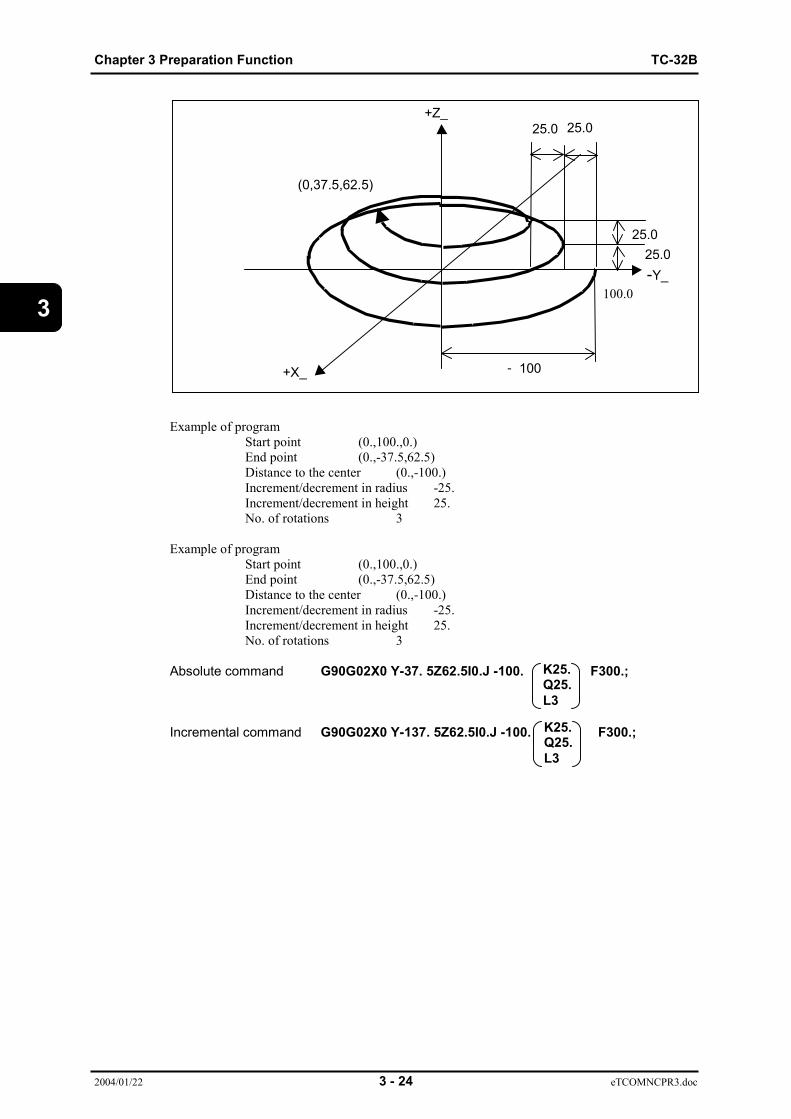
Example of programStart point (0.,100.,0.)End point (0.,-37.5,62.5)Distance to the center (0.,-100.)Increment/decrement in radius -25.Increment/decrement in height 25.No. of rotations 3
Example of programStart point (0.,100.,0.)End point (0.,-37.5,62.5)Distance to the center (0.,-100.)Increment/decrement in radius -25.Increment/decrement in height 25.No. of rotations 3
Absolute command G90G02X0 Y-37. 5Z62.5I0.J -100. F300.;
Incremental command G90G02X0 Y-137. 5Z62.5I0.J -100. F300.;
+Z_
+X_
-Y_
- 100
25.025.0
25.025.0
100.0
(0,37.5,62.5)
K25.Q25.L3
K25.Q25.L3

TC-32B Chapter 3 Preparation Function
2004/01/22 3 - 25 eTCOMNCPR3.doc
3
Cutter compensation can be performed only in offset mode. An alarm will occur when this isattempted in startup or cancel mode.
The setting for [Cutter compensation] is applied to the selected plane during cutter compensation,relative to the start point and target point specified in the program.
An alarm will occur when the programmed conical interpolation tool path or the tool path aftercutter compensation intersects or makes contact with the conical center.
An alarm will occur when the circular cone defined that over the circle radius fudge factor limitpoint by the increment or decrement in radius per rotation does not match the end point.
An alarm will occur when corner CR is specified in the block immediately before a block thatperforms conical interpolation.
Automatic corner override is not possible for the blocks immediately before and after a block thatperforms conical interpolation.
Corner CR cannot be specified for conical interpolation.
An alarm will occur when the cutter compensation direction (G41, G42) is changed between theblocks immediately before and after a block that performs conical interpolation.
An alarm will occur when the radius is specified using command "R."
An alarm will occur when the increment or decrement in radius is zero (0).
An alarm will occur when setting value of selected flat as below. (1) Start point radius = End point radius (2) Start point = Center (3) End point = Center
Not commanded when mirror image is effective.Not commanded when scaling image is effective.
When a cutter compensation cancel command is included in the block immediately after a blockthat performs conical interpolation and cutter compensation, the end point of the conicalinterpolation will be the position given by the vertical vector from the end point of conicalinterpolation on the selected plane.
An in-position check is performed between the blocks immediately before and after a block thatperforms conical interpolation.
Chapter 3 Preparation Function TC-32B
2004/01/22 3 - 26 eTCOMNCPR3.doc
3
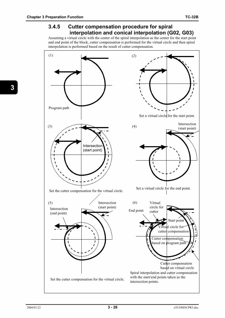
3.4.5 Cutter compensation procedure for spiral interpolation and conical interpolation (G02, G03)Assuming a virtual circle with the center of the spiral interpolation as the center for the start pointand end point of the block, cutter compensation is performed for the virtual circle and then spiralinterpolation is performed based on the result of cutter compensation.
(1)
Program path
Set a virtual circle for the start point.
(2)
(4)
Set a virtual circle for the end point.Set the cutter compensation for the virtual circle.
(6)(5)
Set the cutter compensation for the virtual circle.
Spiral interpolation and cutter compensationwith the start/end points taken as theintersection points.
Intersection(start point)
Intersection(start point)
Intersection(start point)Intersection
(end point)End point
Start point
Cutter compensationbased on virtual circle
Virtual circle forcutter compensation
Cutter compensationbased on program path
Virtualcircle forcutter
ti
(3)
TC-32B Chapter 3 Preparation Function
2004/01/22 3 - 27 eTCOMNCPR3.doc
3
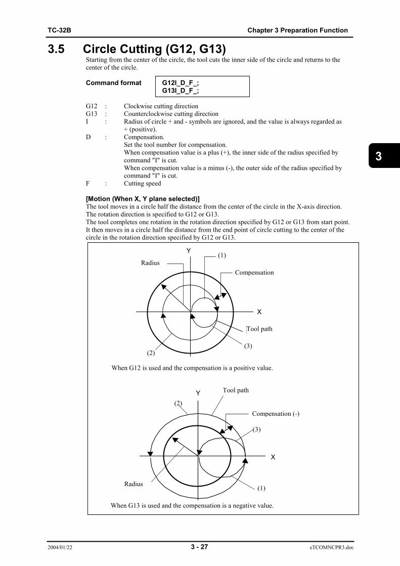
3.5 Circle Cutting (G12, G13)Starting from the center of the circle, the tool cuts the inner side of the circle and returns to thecenter of the circle.
Command format G12I_D_F_;G13I_D_F_;
G12 : Clockwise cutting directionG13 : Counterclockwise cutting directionI : Radius of circle + and - symbols are ignored, and the value is always regarded as
+ (positive).D : Compensation.
Set the tool number for compensation.When compensation value is a plus (+), the inner side of the radius specified bycommand "I" is cut.When compensation value is a minus (-), the outer side of the radius specified bycommand "I" is cut.
F : Cutting speed
[Motion (When X, Y plane selected)]The tool moves in a circle half the distance from the center of the circle in the X-axis direction.The rotation direction is specified to G12 or G13.The tool completes one rotation in the rotation direction specified by G12 or G13 from start point.It then moves in a circle half the distance from the end point of circle cutting to the center of thecircle in the rotation direction specified by G12 or G13.
X
Y
工具経路
X
Y
RadiusCompensation
(1)
Tool path
(3)
When G12 is used and the compensation is a positive value.
(2)
Tool path
(2)
Radius
Compensation (-)
(3)
(1)
When G13 is used and the compensation is a negative value.
Chapter 3 Preparation Function TC-32B
2004/01/22 3 - 28 eTCOMNCPR3.doc
3
An alarm will occur when command "D" is omitted.
An alarm will occur when the product of the radius (command "I") minus compensation is zero (0)or a negative value.
An alarm will occur when the circle cutting command (G12, G13) is specified together with thecutter compensation command (G40, G41, G42) (startup or cancel mode).
Corner CR cannot be set for a block that contains the circle cutting command and the blockimmediately before that block.
An alarm will occur when the radius after cutter compensation is smaller than the tool diameter.
Circle cutting is performed on the plane currently selected (G17, G18, G19).
The start point and end point are the same for circle cutting.
When circle cutting (G12, G13) is executed during cutter compensation (G41, G42), cuttercompensation is valid for the path compensated by command "D."
3.6 Plane Selection (G17, G18, G19)Refer to “3.4. Circular/Helical Interpolation (G02, G03)” for more detail.
TC-32B Chapter 3 Preparation Function
2004/01/22 3 - 29 eTCOMNCPR3.doc
3
3.7 Dwell (G04)Upon completion of the previous block and in-position check, some time elapses before executingthe next block.
Command format G04 P_ ;
G04 X_ ;
P,X : Dwelling time (sec)
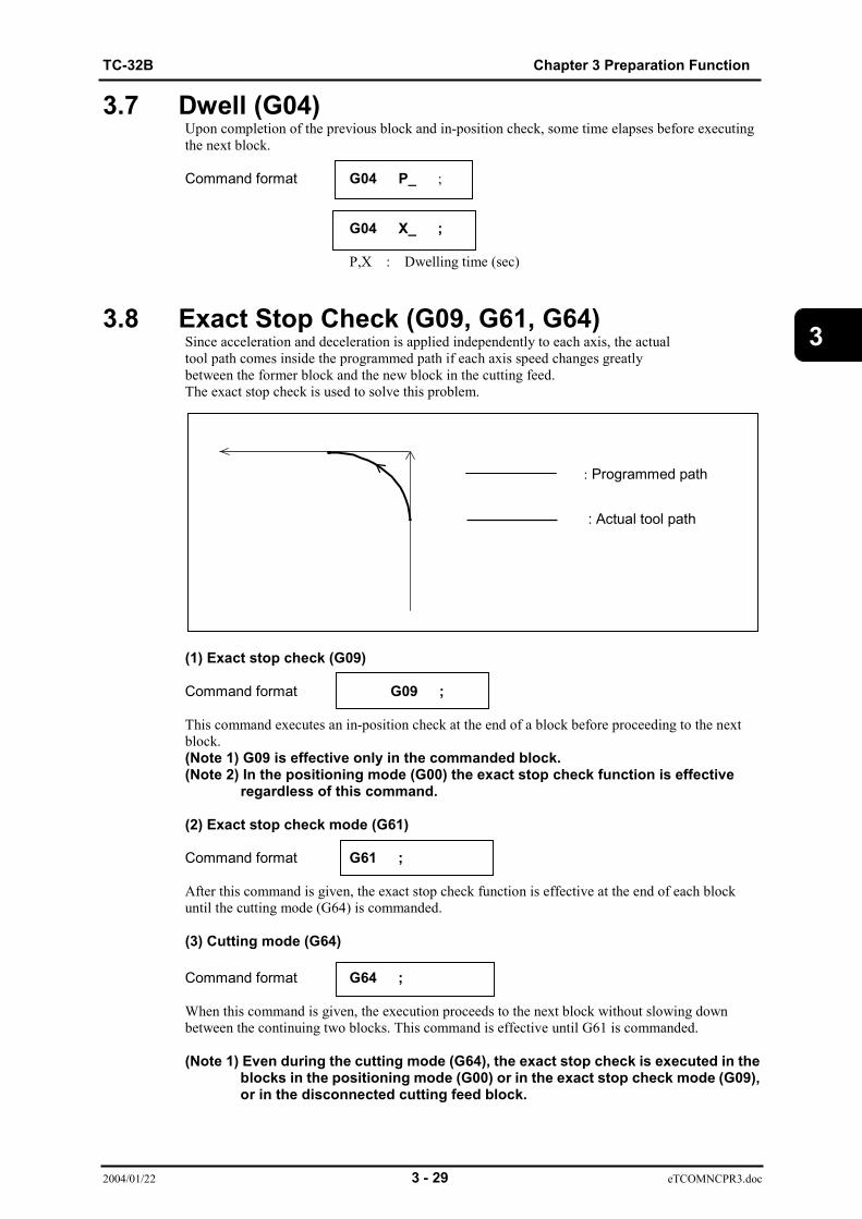
3.8 Exact Stop Check (G09, G61, G64)Since acceleration and deceleration is applied independently to each axis, the actualtool path comes inside the programmed path if each axis speed changes greatlybetween the former block and the new block in the cutting feed.The exact stop check is used to solve this problem.
(1) Exact stop check (G09)
Command format G09 ;
This command executes an in-position check at the end of a block before proceeding to the nextblock.(Note 1) G09 is effective only in the commanded block.(Note 2) In the positioning mode (G00) the exact stop check function is effective
regardless of this command.
(2) Exact stop check mode (G61)
Command format G61 ;
After this command is given, the exact stop check function is effective at the end of each blockuntil the cutting mode (G64) is commanded.
(3) Cutting mode (G64)
Command format G64 ;
When this command is given, the execution proceeds to the next block without slowing downbetween the continuing two blocks. This command is effective until G61 is commanded.
(Note 1) Even during the cutting mode (G64), the exact stop check is executed in the blocks in the positioning mode (G00) or in the exact stop check mode (G09), or in the disconnected cutting feed block.
: Programmed path
: Actual tool path
Chapter 3 Preparation Function TC-32B
2004/01/22 3 - 30 eTCOMNCPR3.doc
3
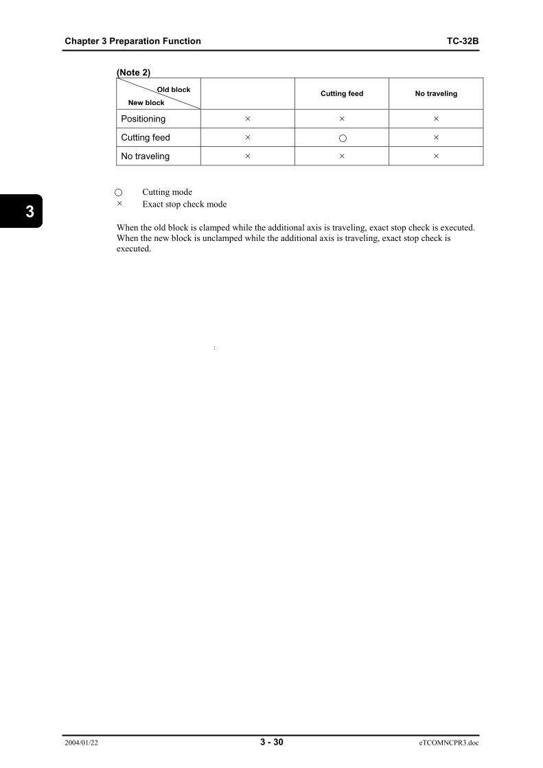
Old blockNew block
(Note 2)
Cutting feed No traveling
Positioning × × ×
Cutting feed × ×
No traveling × × ×
Cutting mode× Exact stop check mode
When the old block is clamped while the additional axis is traveling, exact stop check is executed.When the new block is unclamped while the additional axis is traveling, exact stop check isexecuted.
TC-32B Chapter 3 Preparation Function
2004/01/22 3 - 31 eTCOMNCPR3.doc
3
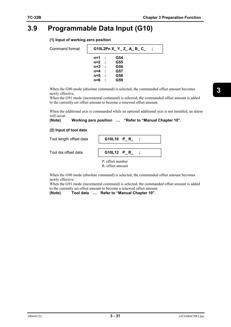
3.9 Programmable Data Input (G10)(1) Input of working zero position
Command format G10L2Pn X_ Y_ Z_ A_ B_ C_ ;
n=1 : G54n=2 : G55n=3 : G56n=4 : G57n=5 : G58n=6 : G59
When the G90 mode (absolute command) is selected, the commanded offset amount becomesnewly effective.When the G91 mode (incremental command) is selected, the commanded offset amount is addedto the currently set offset amount to become a renewed offset amount.
When the additional axis is commanded while an optional additional axis is not installed, an alarmwill occur.(Note) Working zero position … “Refer to “Manual Chapter 10”.
(2) Input of tool data
Tool length offset data G10L10 P_ R_ ;
Tool dia offset data G10L12 P_ R_ ;
P: offset numberR: offset amount
When the G90 mode (absolute command) is selected, the commanded offset amount becomesnewly effective.When the G91 mode (incremental command) is selected, the commanded offset amount is addedto the currently set offset amount to become a renewed offset amount.(Note) Tool data … Refer to “Manual Chapter 10”.

Chapter 3 Preparation Function TC-32B
2004/01/22 3 - 32 eTCOMNCPR3.doc
3
(3) Input of tool fine offset valueWhen tool length /Tool diameter compensation command is issued using the program, the data ofthe fine offset number corresponding to the commanded offset number is automatically reflectedin operation.
Change of tool fine offset data in program
Command format G10L11 P_ R_ ;
G10L13 P_ R_ ;
L11 : Fine offset of tool lengthL13 : Fine compensation of tool diameterP : Fine offset No.
Range : 1~99R : Fine offset amountThe commanded value is added to the compensation amount in absolutemode (G90) nd the preset value in incremental mode (G91).Setting range +/- 99.999 mm +/- 9.9999 inch
(4) Input of measured working coordinate zero point data.
Command format G10L99 Pn X_ Y_ Z_ Q_ ;
n=1 : G54n=2 : G55n=3 : G56n=4 : G57n=5 : G58n=6 : G59Q : The number that stores the measured results.
After automatic measurement (G121 to G129), set the coordinate system based onthe measured position.
Input of additional working coordinate
Command format G10L99 Pn X_ Y_ Z_ Q_ ;
n : Additional working coordinate system (1 to 48).Q : The number that stores the measured results.
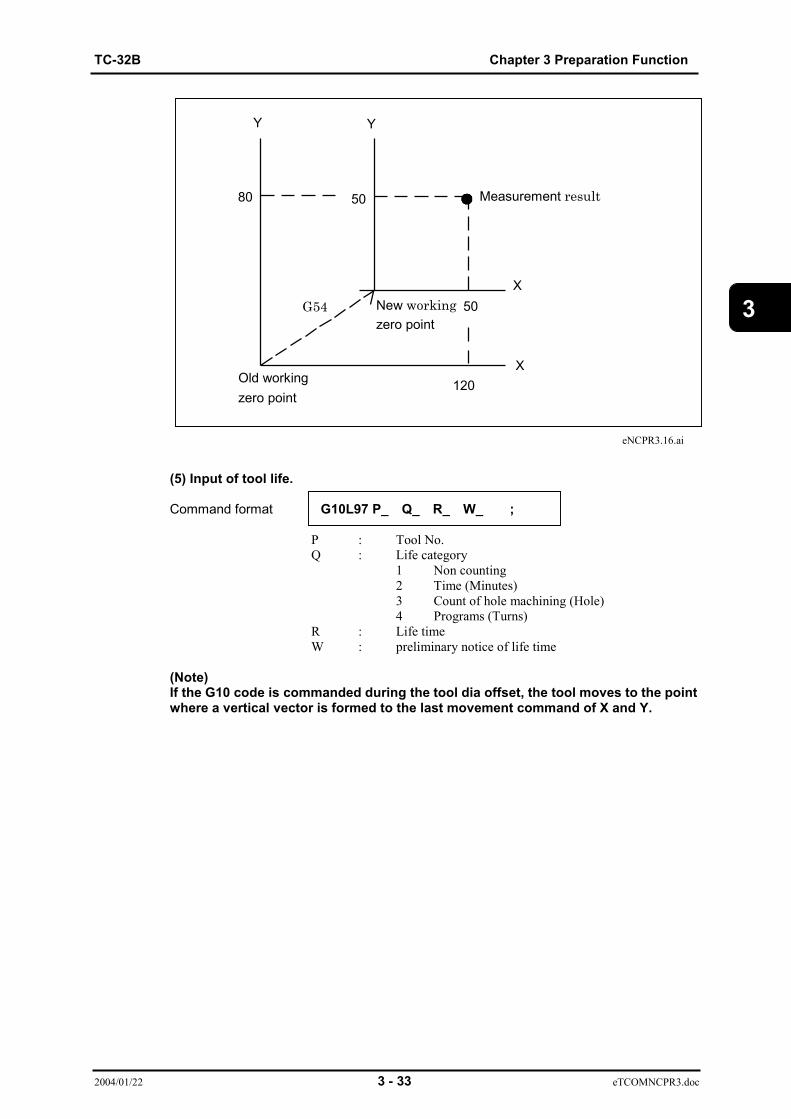
Ex.) Assume that automatic measurement is carried out on the G54 coordinate system and themeasurement result turned out to be (120, 80). Set the coordinate system that this position willbe (50, 50).
(Program)::
G54 G121 X100. Y100. I20. J20. Z-10. R10. ; (Corner measurement)G10 L99 X50. Y50. ;
::
TC-32B Chapter 3 Preparation Function
2004/01/22 3 - 33 eTCOMNCPR3.doc
3
eNCPR3.16.ai
(5) Input of tool life.
Command format G10L97 P_ Q_ R_ W_ ;
P : Tool No.Q : Life category
1 Non counting2 Time (Minutes)3 Count of hole machining (Hole)4 Programs (Turns)
R : Life timeW : preliminary notice of life time
(Note)If the G10 code is commanded during the tool dia offset, the tool moves to the pointwhere a vertical vector is formed to the last movement command of X and Y.
Old workingzero point
80
G54 50
120
50
X
Y Y
XNew workingzero point
Measurement result
Chapter 3 Preparation Function TC-32B
2004/01/22 3 - 34 eTCOMNCPR3.doc
3
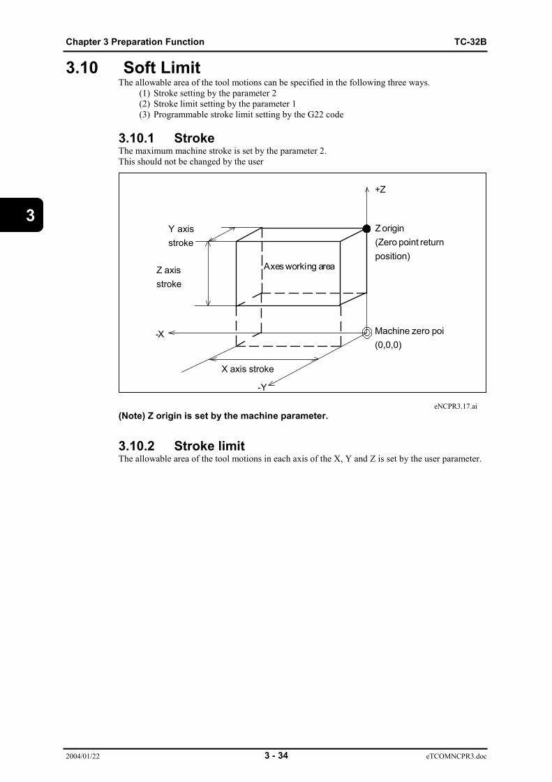
3.10 Soft LimitThe allowable area of the tool motions can be specified in the following three ways.
(1) Stroke setting by the parameter 2 (2) Stroke limit setting by the parameter 1 (3) Programmable stroke limit setting by the G22 code
3.10.1 StrokeThe maximum machine stroke is set by the parameter 2.This should not be changed by the user
eNCPR3.17.ai(Note) Z origin is set by the machine parameter.
3.10.2 Stroke limitThe allowable area of the tool motions in each axis of the X, Y and Z is set by the user parameter.
Axes working area
-X
X axis stroke
Y axisstroke
Z axisstroke
Z origin(Zero point returnposition)
Machine zero poi(0,0,0)
-Y
+Z

TC-32B Chapter 3 Preparation Function
2004/01/22 3 - 35 eTCOMNCPR3.doc
3
3.10.3 Programmable stroke limit (G22)The allowable area of the tool motions is commanded by the program.
Command format G22 X_Y_Z_I_J_K_ ;
X : Programmable stroke limit on + direction of X axis.Y : Programmable stroke limit on + direction of Y axis.Z : Programmable stroke limit on + direction of Z axis.I : Programmable stroke limit on - direction of X axis.J : Programmable stroke limit on - direction of Y axis.K : Programmable stroke limit on - direction of Z axis.
These are commanded with the coordinate values in the machine coordinate system.The command is done by the absolute values regardless of the G90 and G91 codes.
eNCPR3.18.ai
(Note 1) The programmable stroke or the stroke is used as the soft limit in thefollowing ways.G22: The programmable stroke is checked as the soft limit.G23: The stroke is checked as the soft limit.
(Note 2) Right after turning ON the power, the stroke limit set by the userparameter becomes effective.After that, the setting by changing the user parameter or the G22command whichever is done later becomes effective.As for the axis which is not specified by the G22 command, the strokelimit set by the user parameter recognized as the command value.If the stroke limit by the user parameter is changed, however, all theaxes which are not changed become as specified by the userparameter.
(Note 3) The stroke set by the machine parameter is always effective.
-Y(I, J, K)
(X, Y, Z)
-X
Movable area
-Z
Chapter 3 Preparation Function TC-32B
2004/01/22 3 - 36 eTCOMNCPR3.doc
3
3.11 Return to the Reference Point (G28)Command format G28X_Y_Z_A_B_C_;
This command provides an automatic return to the reference point through anintermediate point for commanded axes. Positioning to the reference point is made through anintermediate point as specified by X_Y_Z_A_B_C_. It can be 3.12 Selection of machine coordinate system (G53) commanded by either the absolutecommand (G90) or the incremental command (G91).The coordinate values of the intermediate point commanded in this block are memorized.All the commanded axes are moved to the reference point at the rapid traverse rate by way ofintermediate point.
(Note 1) As for the coordinate value of the intermediate point, only the valuescommanded by this G28 block are newly memorized.The coordinate value of axis not commanded by this G28 block isregarded as that of previous G28 block.
(Note 2) The reference point is set by the user parameter.(Note 3) A tool motion to the intermediate point or the reference point is done by
positioning, and interpolation is not available.(Note 4) During the single block operation, the block stops at the intermediate
point.(Note 5) The coordinate value of the intermediate point is memorized by the
absolute value in the working coordinate system. Therefore, if theworking coordinate system is changed after the G28 is commanded, theintermediate point is also changed to the new coordinate system.
(Note 6) When the additional axis is commanded while an optional additionalaxis is not installed, an alarm will occur.
TC-32B Chapter 3 Preparation Function
2004/01/22 3 - 37 eTCOMNCPR3.doc
3
3.12 Return from the Reference Point (G29)Command format G29X_Y_Z_A_B_C_;
This command provides positioning to the commanded position through an intermediate point forcommanded axes. At an incremental command, an incremental distance from the intermediatepoint must be commanded.The commanded axes are moved to the intermediate point at the rapid traverse rate, thenpositioned at the commanded point.
(Note 1) A tool motion to the intermediate point or the commanded point is doneby positioning, and interpolation is not available.
(Note 2) The tool goes through the intermediate point commanded by the G28 orG30 whichever is given later.
(Note 3) During the single block operation, the block stops at the intermediatepoint.
(Note 4) For axes whose intermediate point is not memorized using G28 or G30,the current position is regarded as the center point.
(Note 5) When the additional axis is commanded while an optional additionalaxis is not installed, an alarm will occur.
3.13 Return to the 2nd to 6th reference point (G30)
Command format G30P_X_Y_Z_A_B_C_;
P2 : Return to the 2nd reference pointP3 : Return to the 3rd reference pointP4 : Return to the 4th reference pointP5 : Return to the 5 reference pointP6 : Return to the 6th reference point
This command moves the axes to the 2nd, to 6th reference point in the same way as commandedby G28.The G29 code can be used as the same way as G28.
(Note 1) The 2nd to 6th reference points are set by the user parameter.(Note 2) When P_ is omitted, return to the 2nd reference point is automatically
selected.(Note 3) When the additional axis is commanded while an optional additional
axis is not installed, an alarm will occur.
3.14 Selection of machine coordinate system (G53)
The coordinate values in the machine coordinate system can be commanded in the followingways.
Command format G53 ;
The coordinate values commanded in the same block as G53 is recognized in the machinecoordinate system.(Note) When the incremental mode (G91) is selected, the G53 command is
ignored.

Chapter 3 Preparation Function TC-32B
2004/01/22 3 - 38 eTCOMNCPR3.doc
3
3.15 Selection of working coordinate system (G54~G59)
When 6 sets of the coordinate systems for each workpiece are set in the data previously,necessary coordinates system can be selected by commanding the G54 through G59 codes.
Command format G54···
G59
G54 : working coordinate system 1G55 : working coordinate system 2G56 : working coordinate system 3G57 : working coordinate system 4G58 : working coordinate system 5G59 : working coordinate system 6
3.16 Additional working coordinate system selection (G54.1)
Command format G54.1 Pn ;
Pn : Specification code for additional working coordinate system.
n : 1~48
The working coordinate system can be selected from 48pairs using the above command.G54 provides this function instead of G54.1.Data setting method1) The data can be confirmed or set on the working coordinate origin screen.2) The data can be set by commanding G10 in the program.
Command format G10 L20 Pn X_Y_Z_ ;
Pn : Specification code for additional workingcoordinate system.
n : 1~48X,Y,Z :Setting value of workpiece origin offset value
When the absolute mode (G90) is selected, the commanded value is considered the offset value.When the incremental mode (G91) is selected, the commanded value is added to the preset offsetvalue.
;
TC-32B Chapter 3 Preparation Function
2004/01/22 3 - 39 eTCOMNCPR3.doc
3
3.17 Scaling (G50, G51)The programmed shape can be enlarged or reduced by the desired scaling factor.Scaling is possible using the same ratio for all axes or a different ratio for each axis.
Scaling using the same ratio for all axes
Command format G51X_Y_Z_P_;
X, Y, Z : Scaling center coordinate axes (workpiece coordinates)P : Scaling factor
Scaling using a different ratio for each axis
Command format G51X_Y_Z_I_J_K_;
X, Y, Z : Scaling center coordinate axes (workpiece coordinates)IJK : Scaling factor of XYZ axes
Scaling / Cancel
Command format G50;
(Note 1) Do not use other GM codes in a block where G51 is used, or an alarmwill occur.
(Note 2) Set the scaling type (scaling using the same ratio for all axes or scalingusing a different ratio for each axis) for the user parameter.
(Note 3) When the scaling factor command (P or IJK) is omitted, the scalingparameter setting (user parameter 1) is used.
(Note 4) When the scaling center coordinates (XYZ) are omitted, the toolposition when G51 is used is regarded as the center coordinates.
(Note 5) Set the scaling factor unit (0.001 or 0.00001) for the parameter.The valid range of the scaling factor command (P or IJK) or scalingfactor parameter is ±1 to ±999999.Accordingly, the valid scaling range is ±0.001 to ±999.999 or ±0.00001 to±9.99999.
(Note 6) The axis does not travel when scaling start (G51) or scaling cancel(G50) is used.

Chapter 3 Preparation Function TC-32B
2004/01/22 3 - 40 eTCOMNCPR3.doc
3
Example of scaling using the same ratio for all axes
Scaling using the same ratio for all axesP0 Scaling centerP1P2P3P4 → P1’P2’P3’P4’
(Note 1) An alarm will occur when scaling is used for an axis that has scalingturned off for the parameter.
(Note 2) An alarm will occur when circle cutting is specified while a differentscaling ratio is set for each axis.
(Note 3) Setting a different scaling ratio for each axis in circular interpolationmode does not result in elliptical interpolation.
(Note 4) When a different scaling ratio is set for each axis and the radius (R) ofthe arc is specified in circular interpolation mode, the larger scalingfactor of the axes forming the plane on which the arc is drawn is appliedto the radius.
E.g.) Arc using command "R": The left and right command formats are equivalent.G90 G00X0.Y100.; G90G00X0.Y100.;G51X0.Y0.Z0.I2000J1000; =G02X100.Y0.R100.F500; G02X200.Y0.R200.F500;
(Note 5) When a different scaling ratio is set for each axis and the center (I, J) ofthe arc is specified in circular interpolation mode, the distance from thestart point to the center (I, J) is not subject to scaling.
E.g.) Arc using commands "I" "J": The left and right command formats areequivalent.
G90 G00X0.Y100.; G90 G00X0.Y100.;G51X0.Y0.I2000J1000; =G02X100.Y0.I0.J-100.F500; G02X200.Y0.I0.J-100.F500;
X
Y
P0
P1
P3’
P2’
P4
P1 P2
P3P4
a
b
c
d
O
Machiningprogramshape
Y-axis
X-axis
Shape afterscaling
Scaling using a different ratio foreachaxisa / b :X-axis scaling factorc / d :Y-axis scaling factorO : Scaling center
TC-32B Chapter 3 Preparation Function
2004/01/22 3 - 41 eTCOMNCPR3.doc
3
Precautions for use of scaling function:
(Note 1) When scaling is invalidTool offset set for [Cutter compensation] and [Tool length offset] is notsubject to scaling.Additional axes are not subject to scaling.An alarm will occur when coordinate transformation (rotationaltransformation, scaling, programmable mirror image) is performed while theadditional axis is selected by the plane selection command (G17, 18, 19).
Axis travel to the R point and ATC zero point specified by the ATC command(G100, M6) is not subject to scaling.Overrun of single direction positioning (G60) is not subject to scaling.
Scaling is not performed for travel amounts generated through manualintervention.
The following are not subject to scaling in a canned cycle:Infeed amount "Q" and relief amount "d" of deep hole cycle (G83, G73, G173,G183) XY-axes shift "Q" of fine balling (G76) and back balling (G87).However, an alarm will occur when the canned cycle is performed while theZ-axis is set for scaling.
(Note 2) Traveling axes when performing scaling or programmable mirror imageWhen using the scaling or programmable mirror image function, the axis notspecified travels according to the specified axis or coordinates.As a result, the following may occur:1. The machine is not operable because the lock signal check is input for an axis not specified.2. The Z-axis travels because the dry run offset is automatically applied.3. An alarm occurs because the specified axis cannot be used.
(Note 3) Cases when an alarm will occurAn alarm will occur when any reference position return related command(G28 to G30) is used during scaling.
An alarm will occur when any coordinate change command (G10L2/20/98/99,G22 to G23, G52 to G59, G92, G92.1) (external workpiece zero offset) is usedduring scaling.
An alarm will occur when any automatic workpiece measurement command(G120 to G129) is used during scaling.
An alarm will occur when any of the following is performed during scaling:Tool change, XY or YZ circular arc (G102/103, 202/203), circular cutting spiralinterpolation or conical interpolation
An alarm will occur when a canned cycle is performed while the Z-axis is setfor scaling.
An alarm will occur when the amount of travel becomes 0 as a result ofscaling.
An alarm will occur when the corner C or R command is used during scaling.
An alarm will occur when scaling is specified in MDI operation.
(Note 4) Scaling is cancelled when M02 or M03 is used or operation is reset.
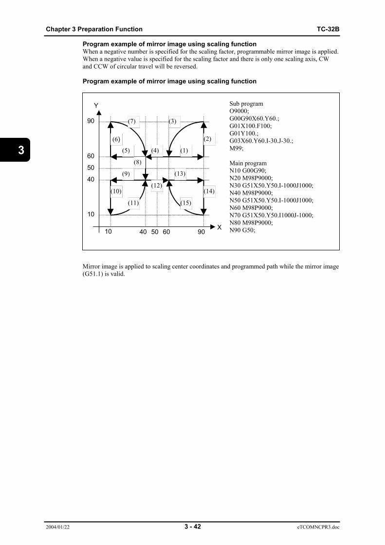
Chapter 3 Preparation Function TC-32B
2004/01/22 3 - 42 eTCOMNCPR3.doc
3
Program example of mirror image using scaling functionWhen a negative number is specified for the scaling factor, programmable mirror image is applied.When a negative value is specified for the scaling factor and there is only one scaling axis, CWand CCW of circular travel will be reversed.
Program example of mirror image using scaling function
Sub programO9000;G00G90X60.Y60.;G01X100.F100;G01Y100.;G03X60.Y60.I-30.J-30.;M99;
Main programN10 G00G90;N20 M98P9000;N30 G51X50.Y50.I-1000J1000;N40 M98P9000;N50 G51X50.Y50.I-1000J1000;N60 M98P9000;N70 G51X50.Y50.I1000J-1000;N80 M98P9000;N90 G50;
Mirror image is applied to scaling center coordinates and programmed path while the mirror image(G51.1) is valid.
10
10
40
40 50
50
60
60
90
90X
Y
(1)
(2)
(3)
(4)(5)
(6)
(7)
(8)
(9)
(10)
(11)
(12)
(13)
(14)
(15)

TC-32B Chapter 3 Preparation Function
2004/01/22 3 - 43 eTCOMNCPR3.doc
3
3.18 Programmable Mirror Image (G50.1, G51.1)Mirror image is applied to the program commands for the axes specified in the program.
Mirror image
Command format G51.1X_Y_Z_;
Mirror image cancel
Command format G50.1X_Y_Z_;
Mirror image setting can be applied simultaneously for the 1st to 3rd axes.
Set the mirror image axis. Omit this for axes about which a mirror image is not created.
Set the mirror image axis in workpiece coordinates.
Using G51.1 command is valid while setting a mirror image. It is regarded as an addition ofmirror axes or a change of the mirror axis coordinates.
Set the axis for canceling mirror image to cancel mirror image. Set the coordinates usingnumerical values.
An alarm will occur when a mirror image is canceled for an axis where mirror image is not set.
(1) Original program command(2) When mirror axis is set for position X50.(3) When mirror axis is set for position X50. Y50.(4) When mirror axis is set for position Y50.
X
Y
100600 40 50
100
60
0
40
50
(1)(2)
(3) (4)
Symmetric axis(X=50)
Symmetric axis(Y=50)
Chapter 3 Preparation Function TC-32B
2004/01/22 3 - 44 eTCOMNCPR3.doc
3
Precautions for use of programmable mirror image:
(Note 1) When programmable mirror image is invalidMirror image is not applied to the positioning direction for single directionpositioning (G60).
Tool length offset is not subject to mirror image setting compensation.
The spindle rotation direction does not change during mirror image setting.
The thread cutting direction does not change during mirror image setting.
Manual intervention allows the axis travel while ignoring the mirror imagesetting.However, when there is a manual interruption during mirror processing, theaxis travels according to the path (tool path) after mirror processing.
(Note 2) Traveling axes when performing scaling or programmable mirror imageWhen using the scaling or programmable mirror image function, the axis notspecified travels according to the specified axis or coordinates. As a result,the following may occur:1. The machine is not operable because the lock signal check is input for an axis not specified.2. The Z-axis travels because the dry run offset is automatically applied.3. An alarm occurs because the specified axis cannot be used.
(Note 3) Cases when an alarm will occurAn alarm will occur when mirror image (G50.1 or G51.1) is used during scalingor rotational transformation.
An alarm will occur when coordinate transformation (rotationaltransformation, scaling, programmable mirror image) is performed while theadditional axis is selected by the plane selection function (G17, 18, 19).
An alarm will occur when any reference position return related command(G28 to G30) is used during mirror image setting.
An alarm will occur when any coordinate change command (G10L2/20/98/99,G22 to G23, G52 to G59, G92, G92.1) (external workpiece zero offset) is usedduring mirror image setting.
An alarm will occur when any automatic workpiece measurement command(G120 to G129, etc.) is used during mirror image setting.
An alarm will occur when any of the following is performed during mirrorimage setting:Tool change, XY or YZ circular arc (G102/103, 202/203), circular cutting spiralinterpolation or conical interpolation
An alarm will occur when a canned cycle is performed while the Z-axis is setfor mirror image.
An alarm will occur when mirror image is specified in MDI operation.
(Note 4) Mirror image is cancelled when M02 or M30 is used or operation isreset.
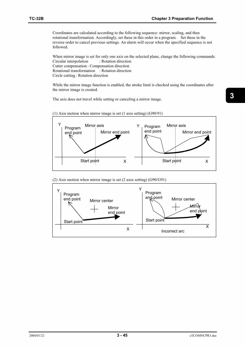
TC-32B Chapter 3 Preparation Function
2004/01/22 3 - 45 eTCOMNCPR3.doc
3
Coordinates are calculated according to the following sequence: mirror, scaling, and thenrotational transformation. Accordingly, set these in this order in a program. Set these in thereverse order to cancel previous settings. An alarm will occur when the specified sequence is notfollowed.
When mirror image is set for only one axis on the selected plane, change the following commands:Circular interpolation : Rotation directionCutter compensation : Compensation directionRotational transformation : Rotation directionCircle cutting : Rotation direction
While the mirror image function is enabled, the stroke limit is checked using the coordinates afterthe mirror image is created.
The axis does not travel while setting or canceling a mirror image.
(1) Axis motion when mirror image is set (1 axis setting) (G90/91)
(2) Axis motion when mirror image is set (2 axes setting) (G90/G91)
Y
XStart point
Mirror axisMirror end point
Programend point
Mirror center
Incorrect arc
Y
XStart point
Mirror axisMirror end point
Programend point
X
Mirrorend point
Start point
YProgramend point Mirror center
X
Mirrorend point
Start point
YProgramend point

Chapter 3 Preparation Function TC-32B
2004/01/22 3 - 46 eTCOMNCPR3.doc
3
3.19 Rotational Transformation Function (G68, G69)
The shape specified in the program is rotated.
Rotational transformation
G17Command format G18 G68α_β_R_;
G19
Rotational transformation cancel
Command format G69;
αβ : Rotation center coordinatesR : Rotation angle (based on CCW)
Plane section command can be omitted. The plane currently selected is valid when it is omitted.
Relationship between selected plane and αβ.
Selected plane α βG17 X YG18 Z XG19 Y Z
Rotation angle (R) is specified within the range of -360.000 to 360.0000 programming mode.
The rotation angle in incremental programming mode is determined in reference to the angle afterthe previous rotational transformation, and in reference to the α axis when it is the first rotationaltransformation.
X
Y
After rotation
Rotation angle
Rotation center Before rotation

TC-32B Chapter 3 Preparation Function
2004/01/22 3 - 47 eTCOMNCPR3.doc
3
An alarm will occur when any reference position return related command (G27, G28, G29, G30) isused during rotational transformation.
An alarm will occur when ccommand (G52 or G92) during rotational transformation.
An alarm will occur when any automatic workpiece measurement command (G131, G132, G120to G129) is used during rotational transformation.
An alarm will occur when any plane selection command (G17, G18, G19) is used during rotationaltransformation.
An alarm will occur when the axes forming the selected plane do not match the axis specified forthe rotation transformation center.
An alarm will occur when the rotational transformation command is used during MDI operation.
An alarm will occur when the linear axis (X, Y, Z) and rotation axis (A, B, C) simultaneousinterpolation command is used during rotational transformation.
Command "R" cannot be omitted. An alarm will occur when it is omitted.
When the rotational transformation command is used while the mirror image and scaling functionsare valid, calculation is performed according to the following sequence:1. Change of rotational transformation center coordinates due to mirror image function2. Change of rotation angle direction for rotational transformation when there is only one
mirror axis3. Change of rotational transformation center coordinates due to scaling function
The rotation angle of the rotational transformation is not subject to scaling.
When a rotational transformation is performed in incremental mode, the current tool position isregarded as the start coordinates.
Rotational transformation is cancelled when M02 or M03 is used or operation is reset.
When the center coordinates are omitted for rotational transformation, the coordinates of thespindle’s current position are regarded as the rotation center coordinates.
Even if the rotation center and angle are changed during rotational transformation, rotationaltransformation using the changed center and angle can be performed without canceling this mode.
Coordinates are calculated according to the following sequence: mirror image, scaling, and thenrotational transformation. Accordingly, set them in this order in a program. Set these in thereverse order to cancel previous settings. An alarm will occur when the specified sequence is notfollowed.

Chapter 3 Preparation Function TC-32B
2004/01/22 3 - 48 eTCOMNCPR3.doc
3
3.20 Coordinate rotation using measured results(G168)Command format G168 X_Y_Q_;
X,Y : Rotation center coordinate value.Q : Selects the desired measured result by setting "1"
to "4".When the selection is omitted, the setting isconsidered to be "1".
The coordinate system commanded in the absolute value is always recognized.When this setting is omitted, the position in which the block has shifted from G69 to G168 (orG68) is considered the center.
The coordinate is rotated using the angle obtained from the measurement.Other features are the same as those for the coordinate rotation function.
3.21 Absolute command and incremental command (G90, G91)
The axis movement amount can be specified by either the absolute command or theincremental command.(1) Absolute command (G90)This is commanded by the G90 code. It specifies an end point of the block in the workingcoordinate system.(2) Incremental command (G91)This is commanded by the G91 code. It specifies a distance from the start point to the end point inthe block.
eNCPR3.19.ai
End point
Start point
Absolute commandG90 X90 Y70 ;
Incremental commandG91 X60 Y40 ;

TC-32B Chapter 3 Preparation Function
2004/01/22 3 - 49 eTCOMNCPR3.doc
3
(3) When additional axis is commanded
1. Absolute command (e.g., B axis)
• When B STROKE of user parameter is set to 1: YES, the B axis rotates to the commandedangle.
• When B STROKE of user parameter is set to 0: NO, the B axis rotates in the directioncloser to the commanded angle.When the commanded angle is the same both in the positive and negative directions (e.g. 180degrees.), the B axis rotates in the positive direction.
• When B STROKE of user parameter is set to 0: NO, even a larger angle than 360 degreesis commanded, this is handled within 360 degrees.
When B STROKE is set to 0: NO
eNCPR3.20.ai
(ex.1) When B0.000 is entered, the axis rotates 90 degrees in the negative direction(ex.2) When B180.000 is entered, the axis rotates 180 degrees in the positive direction(ex.3) When B0.000 is entered, the axis rotates 90 degrees in the negative direction
B-axis machine zero pointB-axis work zero point (Set to 90 degrees in this example)
· B-axis current position before traveling (Angle)
2. Incremental command
Regardless of the setting of B STROKE (1: YES or 0: NO) of user parameter ,the axis rotates for the commanded angle.However, when B STROKE of user parameter is set to 1: YES, STROKE OVERor LIMIT OVER alarm may occur due to stroke and stroke limit control.
Ex.1
Ex.2
Ex.3
Machine position
Absolute position

Chapter 3 Preparation Function TC-32B
2004/01/22 3 - 50 eTCOMNCPR3.doc
3
3.22 Change of workpiece coordinate system (G92)
Change of workpiece zero position can be commanded as follows:
Command format G92X_Y_Z_A_B_C_;
This command shifts the zero position in the working coordinate system so that the current toolposition becomes to the commanded coordinate values.
eNCPR3.21.ai
Ex.) The absolute coordinate of the tool position changes to (80, 60) from the current position (150,100) as commanded "G92 X80. Y60.;"
(Note 1) The commanded coordinate values are always absolute regardless ofG90 and G91.
(Note 2) The working coordinate values of the not commanded axes do notchange.
(Note 3) The current working zero position shifts when G92 is executed, andother working zero positions also shift the same amount accordingly.
Tool position
Y Y'
X
X
Old workpiece zero position
New zero positionShift

TC-32B Chapter 3 Preparation Function
2004/01/22 3 - 51 eTCOMNCPR3.doc
3
eNCPR3.22.aiIn the above figures, G92 is commanded in the coordinate system of G54.When the working zero position of G54 shifts, the other working zero positions of G55 throughG59 also shift the same amount as G54.
(Note 4) When G92 is commanded during the tool dia offset, the tool moves tothe position where the offset vector is formed vertically to the X/Ymovement direction. And the working coordinate system is created withthe current position in the program as commanded by G92.
eNCPR3.23.ai(Note 5) When G92 is commanded during the tool length offset, the working
coordinate system is created so that the target value of theprogrammed Z axis becomes the same as commanded by G92.
New G54working zero position
New G55working zero position
Old G55 working zero positionOld G54 working zero position
Programed paTool path
Working zero position
New zero position
G00X50. Y50. G41D1G01Y100. F1000;X50..........
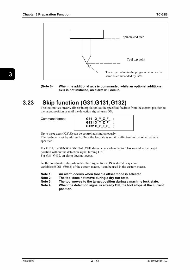
Chapter 3 Preparation Function TC-32B
2004/01/22 3 - 52 eTCOMNCPR3.doc
3
(Note 6) When the additional axis is commanded while an optional additionalaxis is not installed, an alarm will occur.
3.23 Skip function (G31,G131,G132)The tool moves linearly (linear interpolation) at the specified feedrate from the current position tothe target position or until the detection signal turns ON. Command format G31 X_Y_Z_F_ ;
G131 X_Y_Z_F_ ;G132 X_Y_Z_F_ ;
Up to three axes (X,Y,Z) can be controlled simultaneously.The feedrate is set by address F. Once the feedrate is set, it is effective until another value isspecified.
For G131, the SENSOR SIGNAL OFF alarm occurs when the tool has moved to the targetposition without the detection signal turning ON.For G31, G132, an alarm does not occur.
As the coordinate value when detective signal turns ON is stored in systemvariables(#5061~#5063) of the custom macro, it can be used in the custom macro.
Note 1: An alarm occurs when tool dia offset mode is selected.Note 2: The tool does not move during a dry run state.Note 3: The tool moves to the target position during a machine lock state.Note 4: When the detection signal is already ON, the tool stops at the current
position.
Spindle end face
Tool top point
The target value in the program becomes thesame as commanded by G92.

TC-32B Chapter 3 Preparation Function
2004/01/22 3 - 53 eTCOMNCPR3.doc
3
3.24 Continuous skip function (G31)The tool moves linearly (linear interpolation) at the specified feedrate from the current position tothe target position. If the detection signal turns ON in the meantime, the coordinate value when thedetective signal turns ON is stored in the system variables(#5061~#5063) of custom macro.
Command format G31P90X_F_ ;G31P90Y_F_ ;G31P90Z_F_ ;
Note 1: An alarm occurs when tool dia offset mode is selected.Note 2: The tool does not move during a dry run state.Note 3: The tool moves to the target position during a machine lock state.
0.
3.25 Change of tap twisting direction (G133,G134)
G134 I_Command format Z_ S_;
G133 J_
Commanding G133 and G134 rotates the spindle clockwise and counterclockwise respectively.
Z: Z axis target position.Conforms to G90/G91 mode.
I: Thread pitchJ: No, of threadS: Spindle speed
The Z axis is moved synchronousy with the spindle.These are one shot G codes.Command G133/G134 each time even for continuous operation.
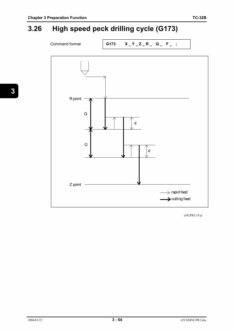
Chapter 3 Preparation Function TC-32B
2004/01/22 3 - 54 eTCOMNCPR3.doc
3
3.26 High speed peck drilling cycle (G173)
Command format G173 X _ Y _ Z _ R _ Q _ F _ ;
eNCPR5.19.ai
rapid feed
cutting feed
R point
Z point
Q
d
dQ

TC-32B Chapter 3 Preparation Function
2004/01/22 3 - 55 eTCOMNCPR3.doc
3
3.27 Peck drilling cycle (G183)
Command format G183 X _ Y _ Z _ R _ Q _ F _ ;
This is cycle where return operation is removed from G83.
eNCPR5.23.ai
rapid feed
cutting feed
R point
Z point
Q
Q
d
d
dwelling for P sec
Chapter 3 Preparation Function TC-32B
2004/01/22 3 - 56 eTCOMNCPR3.doc
3
3.28 Local coordinate system function (G52)Command format G52 X_ Y_ Z_ A_ B_ C_ ;
X, Y, Z, A, B, C: Amount of shift from workpiece coordinate zero pointOperation will be the same regardless of G90 or G91.Amount of shift is applied only to the specified axis.
1) Executing this command creates a local coordinate system in all coordinate systems fromG54 to G59.
2) The workpiece coordinate system does not vary even when this command is executed.3) The local coordinate system of the specified axis is canceled when G92 command is
executed.4) An error will occur when this command is executed during coordinate rotation.5) When this command is executed during tool compensation, the tool moves to the position
where the offset equivalent to the tool diameter is vertically applied to the end point of theprevious block.
6) The local coordinate system is canceled when any of the following operations areperformed:G52 is used to instruct for the command value of the axis.G92 is usedM02 (M30) is used.

TC-32B Chapter 3 Preparation Function
2004/01/22 3 - 57 eTCOMNCPR3.doc
3
3.29 Single direction positioning function (G60)Command format G60 X_Y_Z_A_B_C_ ;
X, Y, Z, A, B, C: Command value of the axis for which single directionpositioning is performed.
Coordinate of end point for G90 and travel amount for G91
eNCPR3.25.ai
Operation is reset.When the above command is executed, the axis moves from the end point for the preset travelamount, and then moves to the end point.G60 is a one shot command and the axis travel path is the same as that for G00.The travel amount is set for the user parameter.
1) Single direction positioning is not performed for the Z-axis during a canned cycle, or theXY-axes when they are moving for the preset amount of shift in the G76 and G87 cycles.
2) Single direction positioning is not performed for any axis that does not have the travelamount set for the parameter.
3) Single direction positioning is performed even when 0 is specified for the travel amount.4) An error will occur when G60 is used during tool compensation.
Single stop does not
Start point
Stop
Travel amount
End point
Start point
Chapter 3 Preparation Function TC-32B
2004/01/22 3 - 58 eTCOMNCPR3.doc
3
3.30 G code priority(1) Executed correctly.(2) Error(3) The last G command is effective.(4) One-shot is executed and the modal is updated.(5) One-shot is executed and the modal is updated, but an error occurs when circle arc is
commanded.(6) Executed when the modal is G0 or G01, but an error occurs when circle arc is commanded.(7) G22 is executed when G22 is commanded and the model for G0 group is updated.
Both are executed when G23 is commanded.(8) An error occurs when circular command is output.(9) An error occurs while circular arc mode is selected.(10) The one commanded after the block is executed.
When G80 group is executed, the model for G00 group is updated.When G0 group is executed, G80 group is canceled.
(11) An error occurs, but both are executed when commanded with G80.(12) One shot execution, modal cancellation.(13) Executed correctly except when the XZ or YZ arc command is executed.(14) An error occurs, but both are executed when commanded with G69.(15) G00 group is executed. G80 is model cancelled.(16) One shot is executed and the model is updated, but an error occurs when G54P is used.(17) Both are executed when the G0 group and model updated are simultaneously with G80.
An error occurs when used simultaneously with G54P.(18) An error occurs when G54P is used.(19) An error occurs when G102, G103, G202, G203 are used.(20) Only effect for G17.(21) An error occurs when G102~G203, without G17 of XY flat selection.(22) An error occurs when already set to the measurement rotation mode.
Only G17 is able to command for G168.(23) An error occurs when Z axis is mirror mode.(24) An error occurs when changing for during the measurement.(25) G68 is effective. G168 is error.

TC-32B Chapter 3 Preparation Function
2004/01/22 3 - 59 eTCOMNCPR3.doc
3
Command the same block (Model-Model)
G177
10
10 1 2 2 2 2 2 1 1 2 2 2 2 1 2 1 2 2 2 1 3 3 1 1 1 3
G98 1 1 1 1 1 1 1 1 1 1 2 2 1 1 1 1 1 2 2 1 1 1 1 1 1 3
G94 1 1 1 1 1 1 1 1 1 1 2 2 1 1 1 1 1 2 2 1 1 1 1 1 3
G90 1 1 1 1 1 1 1 1 1 1 2 2 1 1 1 1 1 2 2 1 1 1 1 3
G80 10
10 1 1 1 1 1 1 1 1 2 2 2 2 1 1 1 2 2 1 1 3 3
G73 10
10 1 2 2 2 2 2 1 1 2 2 2 2 1 2 1 2 2 2 1 3 3
G69 1 1 1 1 1 1 1 2 2 1 2 2 2 2 1 1 1 2 2 3 3
G68
G168
4 19
22
22 2 2 2 2 2 2 2 2 2 2 1 1 1 2 2 3 3
G67 2 2 2 2 2 2 2 2 2 2 2 2 2 2 2 2 2 2 3
G66 2 2 2 2 2 2 2 2 2 2 2 2 2 2 2 2 2 3
G61 1 1 1 1 1 1 1 1 1 1 2 2 1 1 1 1 3
G54 P
1 1 1 1 1 1 1 1 1 1 2 2 2 2 3 3
G54 1 1 1 1 1 1 1 1 1 1 2 2 2 2 3 3
G51.1
4 19 2 2 2 2 2 2 2 2 2 2 3 3
G50.1
4 4 2 2 2 2 2 2 2 2 2 2 3 3
G51 2 2 2 2 2 2 2 2 2 2 3 3
G50 2 2 2 2 2 2 2 2 2 2 3 3
G49 1 8 1 1 2 2 1 1 3 3
G43
G44 1 8 1 1 2 2 1 1 3 3
G41
G42 1 1 2 2 2 2 3 3
G40 1 1 1 1 2 2 3 3
G23 1 1 1 1 3 3
G22 7 7 2 2 3 3
G18
G19 1 19 3 3
G17 1 21 3 3
G2
G3 3 3
G0
G1 3 3
G0,G
1
G2,G
3
G17
G18,G
19
G22
G23
G40
G41,G
42
G43,G
44
G49
G50
G51
G50.1
G51.1
G54
G54 P
G61
G66
G67
G68,G
168
G69
G73
G80
G90
G94
G98
G177

Chapter 3 Preparation Function TC-32B
2004/01/22 3 - 60 eTCOMNCPR3.doc
3
Command the same block (Model-One-shot)
G177
2 1 2 2 2 2 2 2 2 1 1 2 2 2 2 2 2 2 3
G98 1 1 1 1 1 1 1 1 1 1 1 2 1 1 1 1 1 1 1
G94 1 1 1 1 1 1 1 1 1 1 1 2 1 1 1 1 1 1 1
G90 1 1 1 1 1 1 1 1 1 1 1 2 1 1 1 1 1 1 1
G80 1 1 1 1 4 4 4 4 4 1 4 2 4 4 4 4 4 4 3
G73 2 1 2 2 2 2 2 2 2 1 1 2 2 2 2 2 2 2 3
G69 1 1 1 1 1 1 1 1 1 1 1 2 1 1 1 1 1 1 1
G68
G168
2 1 2 1 2 2 2 2 2 1 2 2 2 2 2 2 2 2 2
G67 2 2 2 2 2 2 2 2 2 2 2 2 2 2 2 2 2 2 2
G66 2 2 2 2 2 2 2 2 2 2 2 2 2 2 2 2 2 2 2
G61 1 1 1 1 1 1 1 1 1 1 1 2 1 1 1 1 1 1 1
G54 P
2 1 2 1 2 2 2 2 1 4 1 2 1 1 1 1 1 1 2
G54 1 1 1 1 1 1 1 1 1 4 1 2 1 1 1 1 1 1 1
G51.1
2 1 2 2 2 2 2 2 2 2 2 2 2 2 2 2 2 2 2
G50.1
2 1 2 2 2 2 2 2 2 2 2 2 2 2 2 2 2 2 2
G51 2 2 2 2 2 2 2 2 2 2 2 2 2 2 2 2 2 2 2
G50 2 2 2 2 2 2 2 2 2 2 2 2 2 2 2 2 2 2 2
G49 2 1 2 2 1 1 1 1 2 1 1 2 2 1 1 1 1 2 1
G43
G44 2 1 2 2 1 1 1 1 2 1 1 2 2 1 1 1 1 2 1
G41
G42 2 1 2 2 2 2 2 2 2 1 2 2 2 20 2 2 2 2 2
G40 2 1 2 2 2 2 2 2 2 1 2 2 2 1 2 2 2 2 2
G23 2 1 2 2 2 2 2 2 2 1 2 2 2 2 2 2 2 2 2
G22 2 1 2 2 2 2 2 2 2 1 2 2 2 2 2 2 2 2 2
G18
G19 2 1 2 2 2 2 2 2 2 1 1 2 2 2 2 2 2 2 2
G17 2 1 2 2 2 2 2 20 2 1 1 2 2 2 2 20 2 20
20
G2
G3 4 1 4 4 4 4 4 2 4 1 4 2 4 4 4 2 4 4 10
G0
G1 4 1 4 4 4 4 4 4 4 1 4 2 4 4 4 4 4 4 10
G4
G9
G10
G12
G28
G30
G31
G36
G52
G53
G60
G65
G92
G100
G120
G121
G131
G133
G173

TC-32B Chapter 3 Preparation Function
2004/01/22 3 - 61 eTCOMNCPR3.doc
3
Command the same block (One-shot -One-shot)
G173
2 1 2 2 2 2 2 2 2 1 1 2 2 2 2 2 2 2 3
G133
2 1 2 2 2 2 2 2 2 1 2 2 2 2 2 2 2 3
G131
2 1 2 2 2 2 3 2 2 1 2 2 2 2 2 2 3
G121
2 1 2 2 2 2 2 2 2 1 2 2 2 2 2 3
G120
2 1 2 2 2 2 2 2 2 1 2 2 2 2 3
G100
2 1 2 2 2 2 2 2 2 1 2 2 2 3
G92 2 1 2 2 2 2 2 2 2 1 2 2 3
G65 2 2 2 2 2 2 2 2 2 2 2 3
G60 2 1 2 2 2 2 2 1 2 1 3
G53 1 1 1 1 1 1 1 1 1 3
G52 2 1 2 2 2 2 2 2 3
G36 2 1 2 2 2 2 2 3
G31 2 1 2 2 2 2 3
G30 2 1 2 2 3 3
G28 2 1 2 2 3 3
G12 2 1 2 3
G10 2 1 3
G9 1 3
G4 3
G4
G9
G10
G12
G28
G30
G31
G36
G52
G53
G60
G65
G92
G100
G120
G121
G131
G133
G173
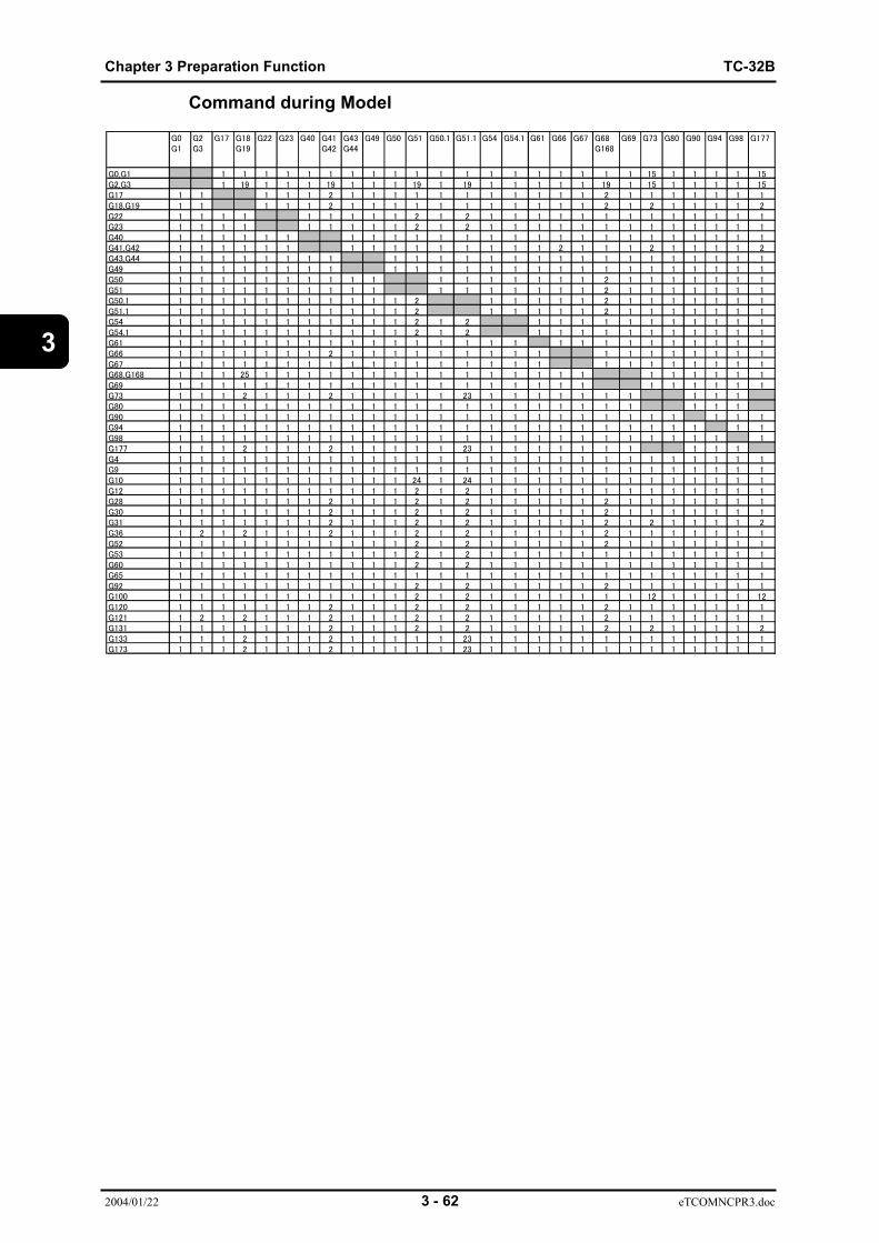
Chapter 3 Preparation Function TC-32B
2004/01/22 3 - 62 eTCOMNCPR3.doc
3
Command during Model
G0G1
G2G3
G17 G18G19
G22 G23 G40 G41G42
G43G44
G49 G50 G51 G50.1 G51.1 G54 G54.1 G61 G66 G67 G68G168
G69 G73 G80 G90 G94 G98 G177
G0,G1 1 1 1 1 1 1 1 1 1 1 1 1 1 1 1 1 1 1 1 15 1 1 1 1 15G2,G3 1 19 1 1 1 19 1 1 1 19 1 19 1 1 1 1 1 19 1 15 1 1 1 1 15G17 1 1 1 1 1 2 1 1 1 1 1 1 1 1 1 1 1 2 1 1 1 1 1 1 1G18,G19 1 1 1 1 1 2 1 1 1 1 1 1 1 1 1 1 1 2 1 2 1 1 1 1 2G22 1 1 1 1 1 1 1 1 1 2 1 2 1 1 1 1 1 1 1 1 1 1 1 1 1G23 1 1 1 1 1 1 1 1 1 2 1 2 1 1 1 1 1 1 1 1 1 1 1 1 1G40 1 1 1 1 1 1 1 1 1 1 1 1 1 1 1 1 1 1 1 1 1 1 1 1 1G41,G42 1 1 1 1 1 1 1 1 1 1 1 1 1 1 1 2 1 1 1 2 1 1 1 1 2G43,G44 1 1 1 1 1 1 1 1 1 1 1 1 1 1 1 1 1 1 1 1 1 1 1 1 1G49 1 1 1 1 1 1 1 1 1 1 1 1 1 1 1 1 1 1 1 1 1 1 1 1 1G50 1 1 1 1 1 1 1 1 1 1 1 1 1 1 1 1 1 2 1 1 1 1 1 1 1G51 1 1 1 1 1 1 1 1 1 1 1 1 1 1 1 1 1 2 1 1 1 1 1 1 1G50.1 1 1 1 1 1 1 1 1 1 1 1 2 1 1 1 1 1 2 1 1 1 1 1 1 1G51.1 1 1 1 1 1 1 1 1 1 1 1 2 1 1 1 1 1 2 1 1 1 1 1 1 1G54 1 1 1 1 1 1 1 1 1 1 1 2 1 2 1 1 1 1 1 1 1 1 1 1 1G54.1 1 1 1 1 1 1 1 1 1 1 1 2 1 2 1 1 1 1 1 1 1 1 1 1 1G61 1 1 1 1 1 1 1 1 1 1 1 1 1 1 1 1 1 1 1 1 1 1 1 1 1 1G66 1 1 1 1 1 1 1 2 1 1 1 1 1 1 1 1 1 1 1 1 1 1 1 1 1G67 1 1 1 1 1 1 1 1 1 1 1 1 1 1 1 1 1 1 1 1 1 1 1 1 1G68,G168 1 1 1 25 1 1 1 1 1 1 1 1 1 1 1 1 1 1 1 1 1 1 1 1 1G69 1 1 1 1 1 1 1 1 1 1 1 1 1 1 1 1 1 1 1 1 1 1 1 1 1G73 1 1 1 2 1 1 1 2 1 1 1 1 1 23 1 1 1 1 1 1 1 1 1 1G80 1 1 1 1 1 1 1 1 1 1 1 1 1 1 1 1 1 1 1 1 1 1 1 1G90 1 1 1 1 1 1 1 1 1 1 1 1 1 1 1 1 1 1 1 1 1 1 1 1 1 1G94 1 1 1 1 1 1 1 1 1 1 1 1 1 1 1 1 1 1 1 1 1 1 1 1 1 1G98 1 1 1 1 1 1 1 1 1 1 1 1 1 1 1 1 1 1 1 1 1 1 1 1 1 1G177 1 1 1 2 1 1 1 2 1 1 1 1 1 23 1 1 1 1 1 1 1 1 1 1G4 1 1 1 1 1 1 1 1 1 1 1 1 1 1 1 1 1 1 1 1 1 1 1 1 1 1 1G9 1 1 1 1 1 1 1 1 1 1 1 1 1 1 1 1 1 1 1 1 1 1 1 1 1 1 1G10 1 1 1 1 1 1 1 1 1 1 1 24 1 24 1 1 1 1 1 1 1 1 1 1 1 1 1G12 1 1 1 1 1 1 1 1 1 1 1 2 1 2 1 1 1 1 1 1 1 1 1 1 1 1 1G28 1 1 1 1 1 1 1 2 1 1 1 2 1 2 1 1 1 1 1 2 1 1 1 1 1 1 1G30 1 1 1 1 1 1 1 2 1 1 1 2 1 2 1 1 1 1 1 2 1 1 1 1 1 1 1G31 1 1 1 1 1 1 1 2 1 1 1 2 1 2 1 1 1 1 1 2 1 2 1 1 1 1 2G36 1 2 1 2 1 1 1 2 1 1 1 2 1 2 1 1 1 1 1 2 1 1 1 1 1 1 1G52 1 1 1 1 1 1 1 1 1 1 1 2 1 2 1 1 1 1 1 2 1 1 1 1 1 1 1G53 1 1 1 1 1 1 1 1 1 1 1 2 1 2 1 1 1 1 1 1 1 1 1 1 1 1 1G60 1 1 1 1 1 1 1 1 1 1 1 2 1 2 1 1 1 1 1 1 1 1 1 1 1 1 1G65 1 1 1 1 1 1 1 1 1 1 1 1 1 1 1 1 1 1 1 1 1 1 1 1 1 1 1G92 1 1 1 1 1 1 1 1 1 1 1 2 1 2 1 1 1 1 1 2 1 1 1 1 1 1 1G100 1 1 1 1 1 1 1 1 1 1 1 2 1 2 1 1 1 1 1 1 1 12 1 1 1 1 12G120 1 1 1 1 1 1 1 2 1 1 1 2 1 2 1 1 1 1 1 2 1 1 1 1 1 1 1G121 1 2 1 2 1 1 1 2 1 1 1 2 1 2 1 1 1 1 1 2 1 1 1 1 1 1 1G131 1 1 1 1 1 1 1 2 1 1 1 2 1 2 1 1 1 1 1 2 1 2 1 1 1 1 2G133 1 1 1 2 1 1 1 2 1 1 1 1 1 23 1 1 1 1 1 1 1 1 1 1 1 1 1G173 1 1 1 2 1 1 1 2 1 1 1 1 1 23 1 1 1 1 1 1 1 1 1 1 1 1 1

TC-32B Chapter4 Preparation function (Tool offset function)
2004/01/22 4 - 1 eTCOMNCPR4.doc
4
CHAPTER 4
4.1 Tool dia offset (G40, G41, G42)4.2 Tool length offset (G43, G44, G49)
PREPARATOION FUNCTION(TOOL OFFSET FUNCTION)

Chapter4 Preparation function (Tool offset function) TC-32B
2004/01/22 4 - 2 eTCOMNCPR4.doc
4
4.1 Tool dia offset (G40, G41, G42)4.1.1 Tool dia offset functionProgramming is done according to the actual workpiece form, but this functionenables the tool to move along the path with an offset from actual workpiece form, which isequivalent to the used tool radius.
G41Command format Dn;
G42
G codes and D code used for tool dia offsetG40 : Tool dia offset cancel (Effective at power ON)G41 : Left offset along tool pathG42 : Right offset along tool pathG41 and G42 command an offset mode, while G40 commands a cancel of the offset mode.
eNCPR4.01.aiDn : Tool offset number (n=0~99)
The offset amount of D0 is always zero.The offset amount is set on the tool data setting screen.
(Note1) Refer to "Chapter 10" in the Instruction Manual for details of the tooldata setting screen.
(Note2) When a command without X and Y axis travel of more than three blocksor a command with a travel amount of zero (0) is given in tool dia. offsetmode, excessive cutting or insufficient cutting may occur, respectively.
4.1.1.1 Tool dia fine compensationWhen G41and G42 are commanded in the program, the tool dlameter fine compensation valuecorresponding to the commanded tool number is added tothetool diameter compensation value.The tooldiameter fine compensation value is placed on the tool list screen.
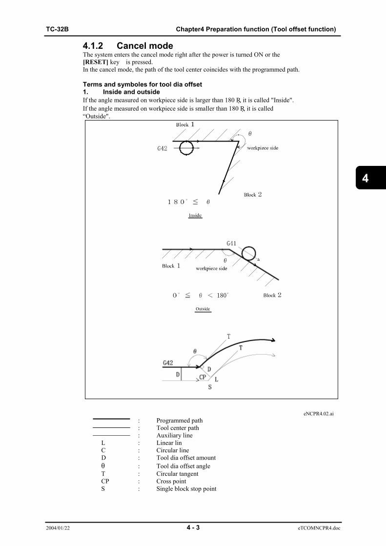
TC-32B Chapter4 Preparation function (Tool offset function)
2004/01/22 4 - 3 eTCOMNCPR4.doc
4
4.1.2 Cancel modeThe system enters the cancel mode right after the power is turned ON or the[RESET] key is pressed.In the cancel mode, the path of the tool center coincides with the programmed path.
Terms and symboles for tool dia offset1. Inside and outsideIf the angle measured on workpiece side is larger than 180 ー, it is called "Inside".If the angle measured on workpiece side is smaller than 180 ー, it is called“Outside".
eNCPR4.02.ai: Programmed path: Tool center path: Auxiliary line
L : Linear linC : Circular lineD : Tool dia offset amountθ : Tool dia offset angleT : Circular tangentCP : Cross pointS : Single block stop point

Chapter4 Preparation function (Tool offset function) TC-32B
2004/01/22 4 - 4 eTCOMNCPR4.doc
4
4.1.3 Start-upWhen a block which satisfies all the following conditions is executed in the cancel mode, thesystem enters the offset mode. The control in this operation is called the start-up.
a) G41 or G42 is commanded.b) The tool offset number is not zero.b) The movement command other than circular arc (G02 or G03) is given on the X-Y plane,and the movement distance is not zero.(Note 1) In the case of circular arc command, an alarm is generated.(Note 2) Command the G0, G1, G2, or G3 first before command the G41/G42.
4.1.3.1 Inside cutting (180 ≤ θ )
Linear-Linear
Linear-Arc

TC-32B Chapter4 Preparation function (Tool offset function)
2004/01/22 4 - 5 eTCOMNCPR4.doc
4
4.1.3.2 Outside cutting(a)Type 1 : Linear - Linear
Type 1 : Linear - Arc
(b)Type 2 : Linear - Linear
Type 2 : Linear - Arc
(Note 1) Type 1 and 2 can be selected in parameter 1 for start-up and cancelmotions.
(Note 2) If the angle is close to 180˚ (179˚ ≤ θ < 180˚) while type 2 is beingselected,actual movement will be type 1.
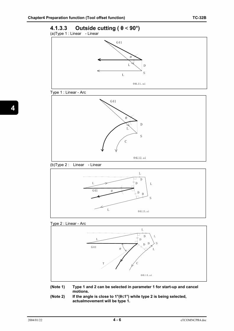
Chapter4 Preparation function (Tool offset function) TC-32B
2004/01/22 4 - 6 eTCOMNCPR4.doc
4
4.1.3.3 Outside cutting ( θ < 90°)(a)Type 1 : Linear - Linear
Type 1 : Linear - Arc
(b)Type 2 : Linear - Linear
Type 2 : Linear - Arc
(Note 1) Type 1 and 2 can be selected in parameter 1 for start-up and cancelmotions.
(Note 2) If the angle is close to 1°(θ≤1°) while type 2 is being selected,actualmovement will be type 1.
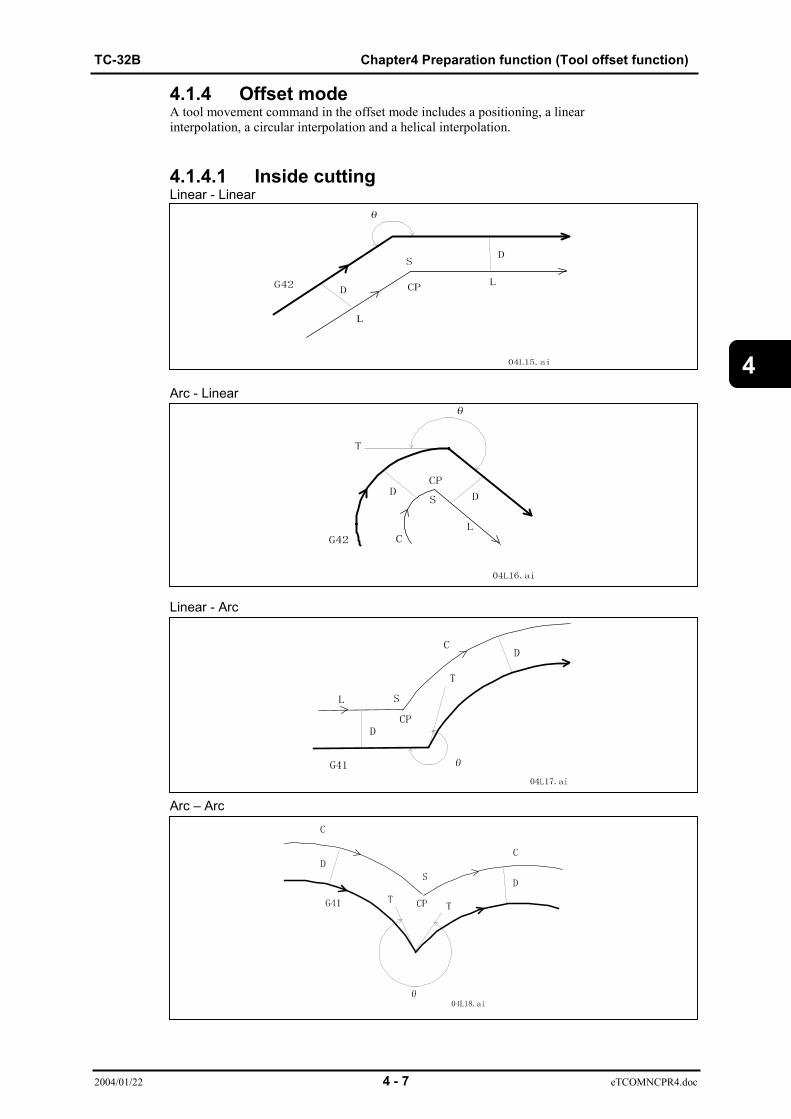
TC-32B Chapter4 Preparation function (Tool offset function)
2004/01/22 4 - 7 eTCOMNCPR4.doc
4
4.1.4 Offset modeA tool movement command in the offset mode includes a positioning, a linearinterpolation, a circular interpolation and a helical interpolation.
4.1.4.1 Inside cuttingLinear - Linear
Arc - Linear
Linear - Arc
Arc – Arc
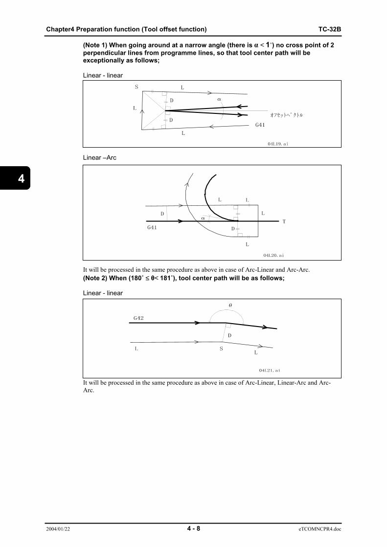
Chapter4 Preparation function (Tool offset function) TC-32B
2004/01/22 4 - 8 eTCOMNCPR4.doc
4
(Note 1) When going around at a narrow angle (there is α < 1˚) no cross point of 2perpendicular lines from programme lines, so that tool center path will beexceptionally as follows;
Linear - linear
Linear –Arc
It will be processed in the same procedure as above in case of Arc-Linear and Arc-Arc.(Note 2) When (180˚ ≤ θ< 181˚), tool center path will be as follows;
Linear - linear
It will be processed in the same procedure as above in case of Arc-Linear, Linear-Arc and Arc-Arc.

TC-32B Chapter4 Preparation function (Tool offset function)
2004/01/22 4 - 9 eTCOMNCPR4.doc
4
4.1.4.2 Outside cutting (90°≤θ<180°)Linear - Linear
Linear - Arc
Arc - Linear
Arc - Arc
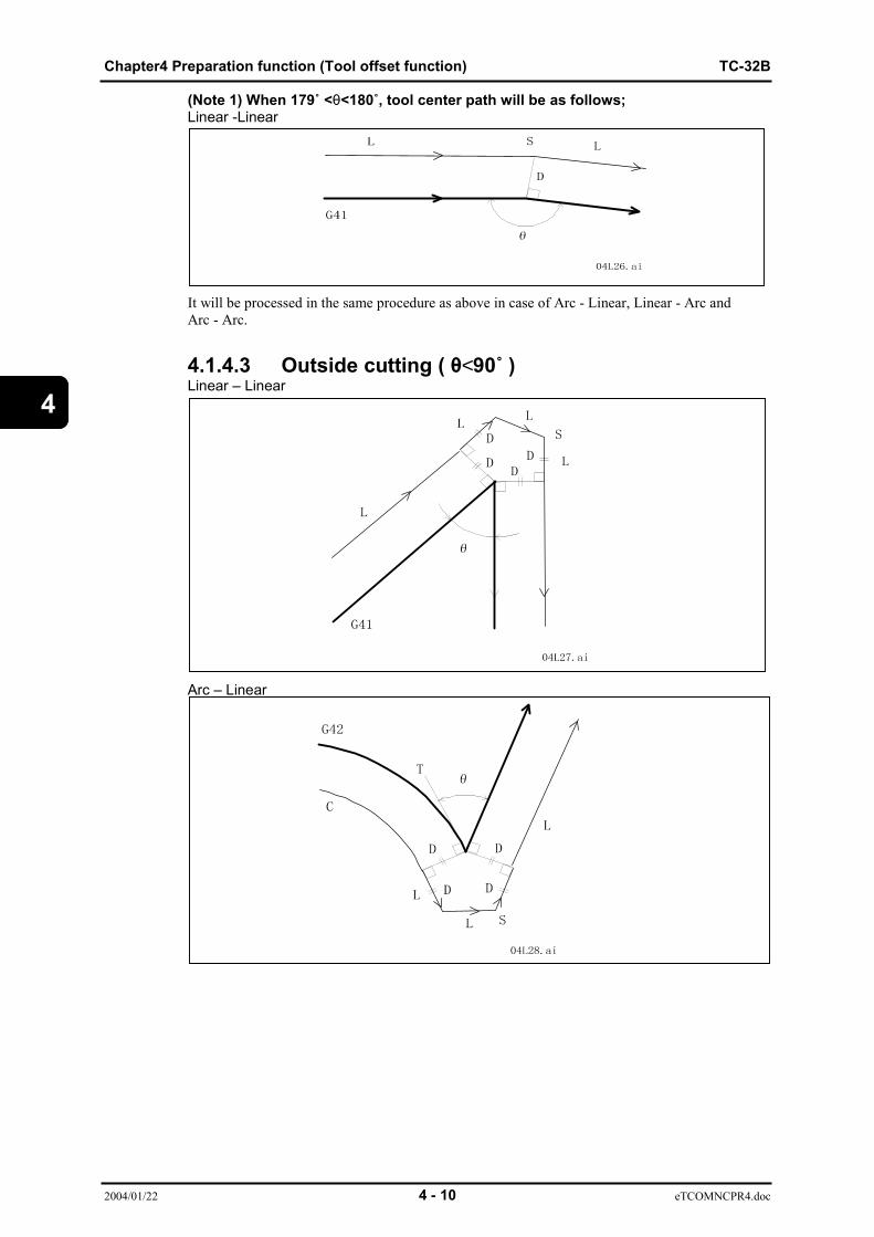
Chapter4 Preparation function (Tool offset function) TC-32B
2004/01/22 4 - 10 eTCOMNCPR4.doc
4
(Note 1) When 179˚ <θ<180˚, tool center path will be as follows;Linear -Linear
It will be processed in the same procedure as above in case of Arc - Linear, Linear - Arc andArc - Arc.
4.1.4.3 Outside cutting ( θ<90˚ )Linear – Linear
Arc – Linear
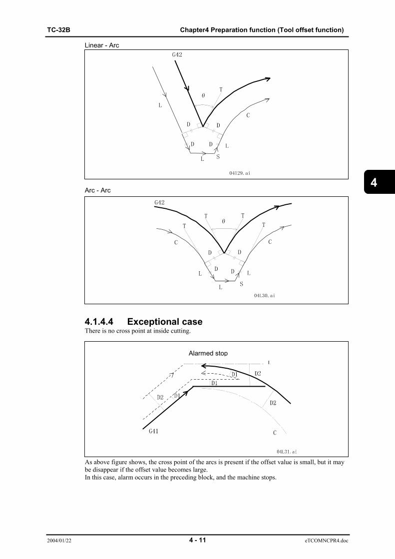
TC-32B Chapter4 Preparation function (Tool offset function)
2004/01/22 4 - 11 eTCOMNCPR4.doc
4
Linear - Arc
Arc - Arc
4.1.4.4 Exceptional caseThere is no cross point at inside cutting.
As above figure shows, the cross point of the arcs is present if the offset value is small, but it maybe disappear if the offset value becomes large.In this case, alarm occurs in the preceding block, and the machine stops.
Alarmed stop

Chapter4 Preparation function (Tool offset function) TC-32B
2004/01/22 4 - 12 eTCOMNCPR4.doc
4
4.1.5 Offset cancelWhen the command satisfying all the conditions as shown below is executed in the offset mode,the offset cancel mode becomes effective.The tool motion in this status is called an offset cancel.
a) G40 is commanded.
Command format G40 ;
b) The movement commanded by G0 or G1.(Note 1) In the case of other command, an alarm is generated.
4.1.5.1 Inside cutting (180˚ ≤ θ)Linear - Linear
Arc - Linear
4.1.5.2 Outside cutting (90˚ ≤ θ ≤ 180˚)
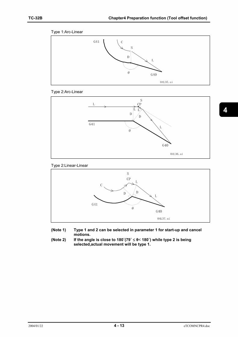
TC-32B Chapter4 Preparation function (Tool offset function)
2004/01/22 4 - 13 eTCOMNCPR4.doc
4
Type 1:Arc-Linear
Type 2:Arc-Linear
Type 2:Linear-Linear
(Note 1) Type 1 and 2 can be selected in parameter 1 for start-up and cancelmotions.
(Note 2) If the angle is close to 180˚(79˚ ≤ θ< 180˚) while type 2 is beingselected,actual movement will be type 1.
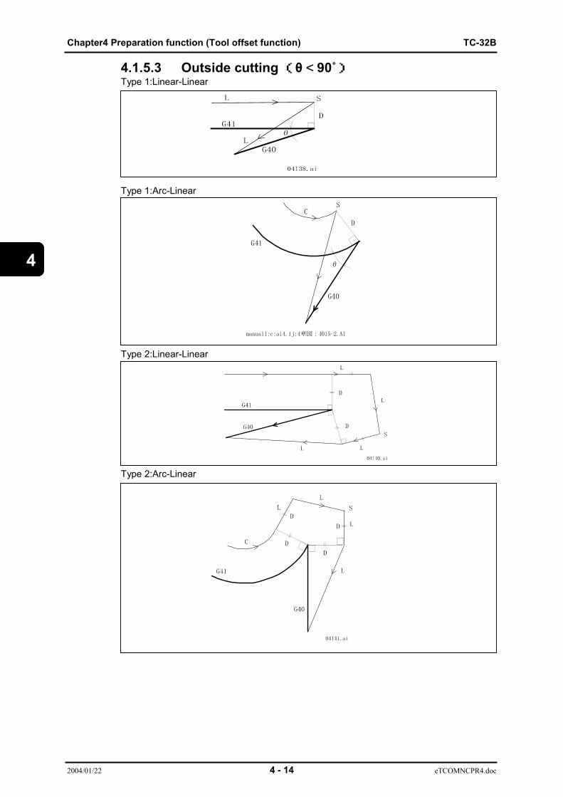
Chapter4 Preparation function (Tool offset function) TC-32B
2004/01/22 4 - 14 eTCOMNCPR4.doc
4
4.1.5.3 Outside cutting(θ < 90˚)Type 1:Linear-Linear
Type 1:Arc-Linear
Type 2:Linear-Linear
Type 2:Arc-Linear
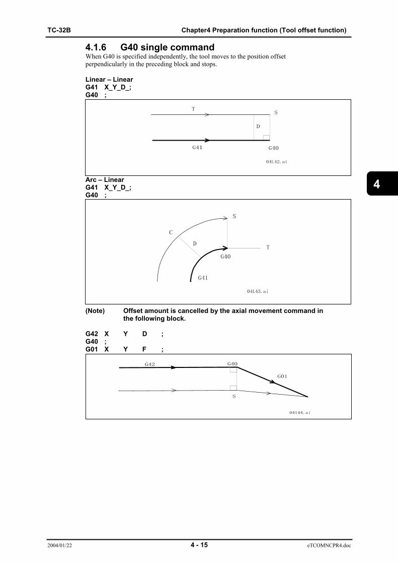
TC-32B Chapter4 Preparation function (Tool offset function)
2004/01/22 4 - 15 eTCOMNCPR4.doc
4
4.1.6 G40 single commandWhen G40 is specified independently, the tool moves to the position offsetperpendicularly in the preceding block and stops.
Linear – LinearG41 X_Y_D_;G40 ;
Arc – LinearG41 X_Y_D_;G40 ;
(Note) Offset amount is cancelled by the axial movement command inthe following block.
G42 X Y D ;G40 ;G01 X Y F ;

Chapter4 Preparation function (Tool offset function) TC-32B
2004/01/22 4 - 16 eTCOMNCPR4.doc
4
Offset amount sign
4.1.7 Change of offset direction in offset modeBy commanding G41 or G42, or converting the algebraic sign (+, -) of the offset amount, theoffset direction can be changed even in the offset mode.The block not to be changed the next of start block.As same as miller (Single axis commanding) and the case of changing the offset directon when Dadress position changed.
G code + -
G41 Left side offset Right side offset
G42 Right side offset Left side offset
Conditions of executionOffset mode command Linear-Linear Linear-Arc Arc-Linear Arc-Arc
G41 G41
G42 G42Perform
G41 G42
G42 G41Perform Perform
When the offset direction is changed, the "inside" and "outside" cuttings are notdiscriminated. But whether there is a cross point or not discriminates those cuttings.The offset amount described hereafter has a positive value.
Where the offset equivalent to the tooldia is vertically applied to the end pointof the previous block
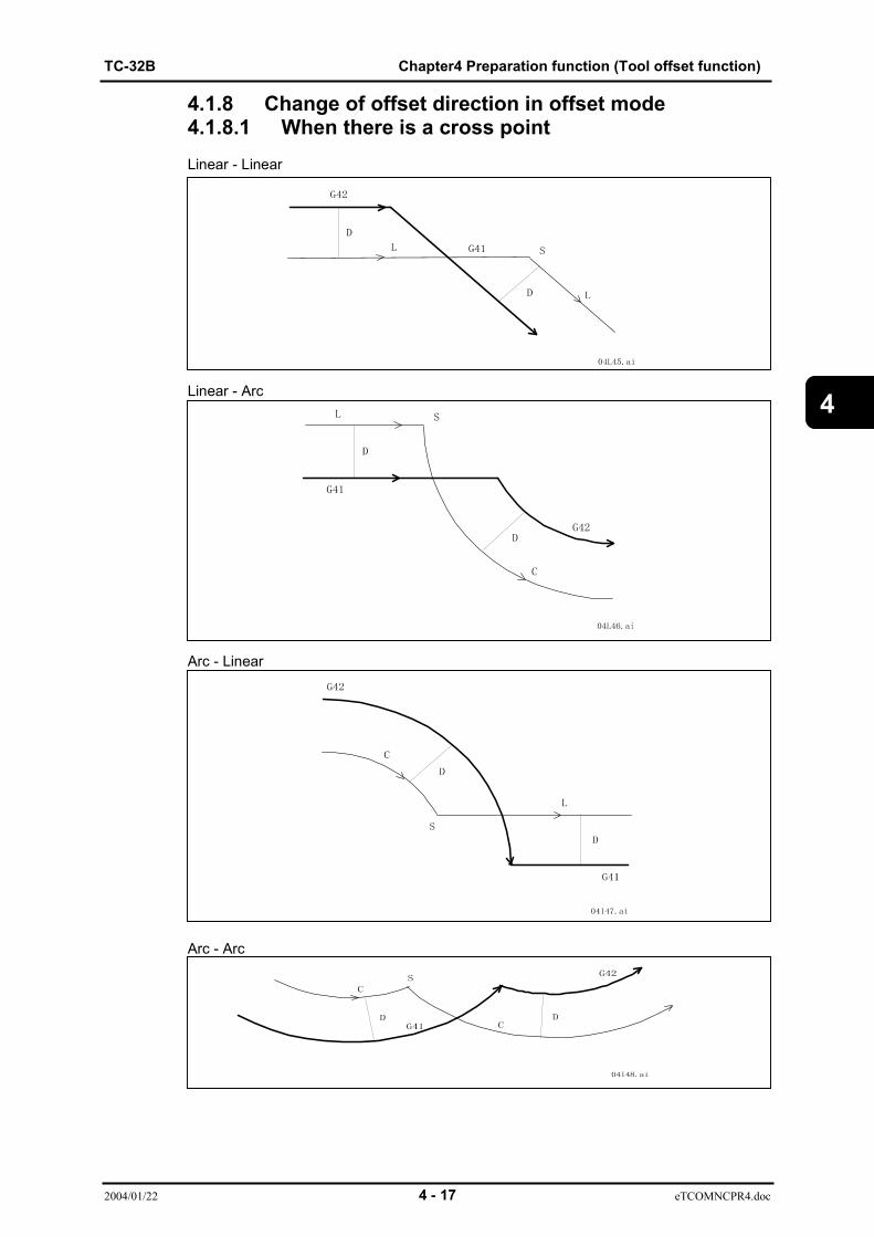
TC-32B Chapter4 Preparation function (Tool offset function)
2004/01/22 4 - 17 eTCOMNCPR4.doc
4
4.1.8 Change of offset direction in offset mode4.1.8.1 When there is a cross pointLinear - Linear
Linear - Arc
Arc - Linear
Arc - Arc
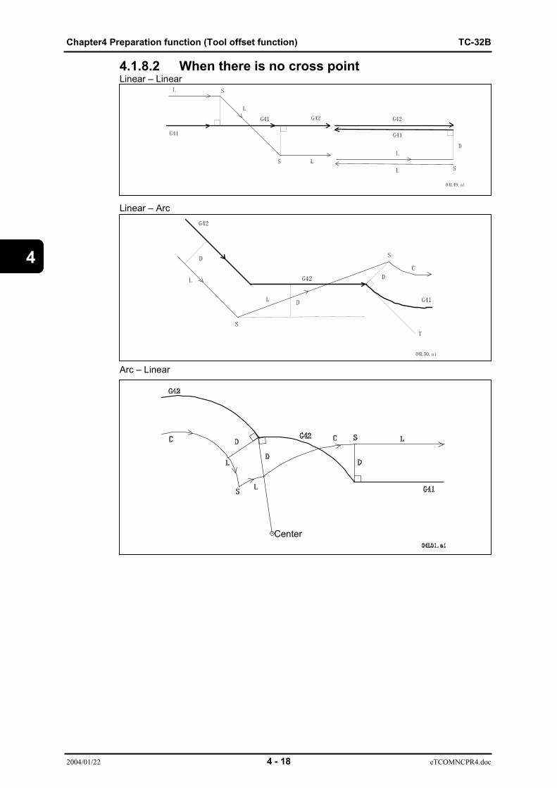
Chapter4 Preparation function (Tool offset function) TC-32B
2004/01/22 4 - 18 eTCOMNCPR4.doc
4
4.1.8.2 When there is no cross pointLinear – Linear
Linear – Arc
Arc – Linear
Center
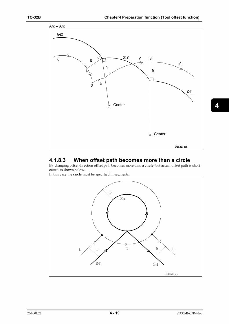
TC-32B Chapter4 Preparation function (Tool offset function)
2004/01/22 4 - 19 eTCOMNCPR4.doc
4
Arc – Arc
4.1.8.3 When offset path becomes more than a circleBy changing offset direction offset path becomes more than a circle, but actual offset path is shortcutted as shown below.In this case the circle must be specified in segments.
Center
Center

Chapter4 Preparation function (Tool offset function) TC-32B
2004/01/22 4 - 20 eTCOMNCPR4.doc
4
4.1.9 G code command for tool dia offset in offset modeLinear - Linear
Linear - Arc
Arc - Linear
Arc - Arc

TC-32B Chapter4 Preparation function (Tool offset function)
2004/01/22 4 - 21 eTCOMNCPR4.doc
4
4.1.10 Notes on tool dia offset(1) Command of tool dia offset amountThe offset amount is commanded by the number of the D command.When G41 or G42 is commanded, the offset amount is commanded in the same block.If it is omitted, the number of D command previously used becomes effective.
(2) Change of tool dia offset amountWhen the offset amount is changed in the offset mode, the offset amount is changed at the endpoint of the block.
N1 G41 X_Y_D1;N6 Xa1 Yb1;N7 Xa2 D2;....Change of offset amountN8 Xa3 Yb3;
(3) Current position displayThe current position display corresponds to the tool center position
(4) Machining of inner wall of circular arc smaller than the used tool radius
Since cutting is not available, the operation stops at the end point of the previous block and analarm is generated.
Alarmed stop
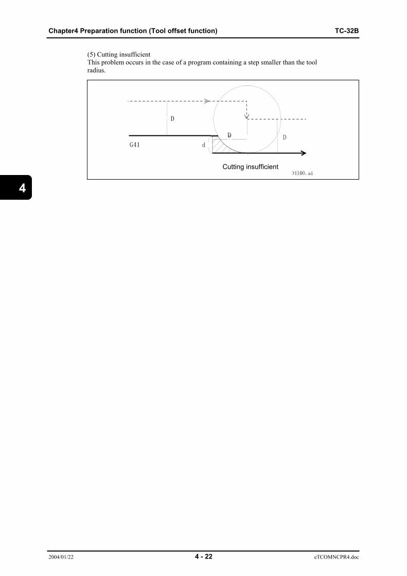
Chapter4 Preparation function (Tool offset function) TC-32B
2004/01/22 4 - 22 eTCOMNCPR4.doc
4
(5) Cutting insufficientThis problem occurs in the case of a program containing a step smaller than the toolradius.
Cutting insufficient

TC-32B Chapter4 Preparation function (Tool offset function)
2004/01/22 4 - 23 eTCOMNCPR4.doc
4
(6) Corner movementWhen cutting the outer side, the tool moves around the corner from different angles.Themovement mode and the feedrate up to the single block stop point are as specified in the currentblock.
When the movement amount around the corner is small as shown in the figure below and thefollowing conditions are satisfied, the movement is ignored.∆VX ≤ ∆V and ∆VY ≤ ∆VThe value ∆V is set by the parameter 1.
Thus, extremely small movements around the corner can be reduced.This function is not available if the following block is a full circular arc.

Chapter4 Preparation function (Tool offset function) TC-32B
2004/01/22 4 - 24 eTCOMNCPR4.doc
4
The original movement in the above figure are:P0-P1-P2 Linear movementP2-P3 Linear movement
The tool moves once around the circular arc afterwards with P3 as the target.If this small movement function is used, the movement from P2 to P3 is ignored andexecuted as follows:
P0-P1-P2 Linear movementP2-P3 (small) circular movement
A full circular is ignored and the movement from P2 to P3 becomes a small circularmovement, thus ignoring this function.

TC-32B Chapter4 Preparation function (Tool offset function)
2004/01/22 4 - 25 eTCOMNCPR4.doc
4
(7) Block without movementWhen the command without any X/Y movement is given for more than 3 blocks during the tooldia offset mode, the movement is as shown below and overcutting or undercutting occurs.
N4 X_Y_;N5 X0;N6 X_;N7 Z_;N8 X;
(Note 1) The block with the movement amount zero will result in the same as above.
N4 G91 X_Y_;N5 X0;N6 X_;
(Note 2) Even if the X/Y movement command is not given at the start-up, thestart-up motion begins at the time the X or Y movement command isexecuted.

Chapter4 Preparation function (Tool offset function) TC-32B
2004/01/22 4 - 26 eTCOMNCPR4.doc
4
(8) Tool movement in case of tool dia offset amount zeroa) Start-upWhen G41 or G42 is commanded in the cancel mode, the offset mode becomeseffective but the start-up motion is not available as the offset amount is zero.When another offset number is specified and the offset amount is not zero, the motion becomesthesame as the case of changing the tool dia offset amount as described in (2).
N1 X_Y_D1; (D1=0)N2 X_;N3 Y_D2; (D2≠0)N4 X_Y_;
b) During offset modeIf the offset amount is changed to zero in the offset mode, the cancel mode is not available anylonger. The motion becomes the same as the case of changing the tool dia offset amount asdescribed in (2).Even if the offset number is changed again and the offset amount is not zero, the motion becomesthe same as the case of changing the tool dia offset amount as described in (2).
N1 X_Y_;N2 X_D1; (D1=0)N3 X_Y_;N4 X_Y_D2 (D2≠0)N5 X_;

TC-32B Chapter4 Preparation function (Tool offset function)
2004/01/22 4 - 27 eTCOMNCPR4.doc
4
(9) Exceptional case or alarm-generating command1.Command to produce the vertical vector
G10 : Programmable data inputG52 : Local coordinate systemG92 : Coordinate system setting#3000:Alarm display#3006: Message display & stop
When the above command is given, the tool moves to the point which is offset as much as the tooldia as specified by the last X/Y movement command.
2.Forcible tool dia offset cancelM06 : Tool changeG100 : Non-stop ATC
When the above command is given, G40 (tool dia offset cancel) becomes automatically effectiveand the tool moves to the point which is offset as much as the tool dia as specified by the last X/Ymovement command.
3.Alarm-generating commandG28 : Return to reference pointG29 : Return from reference pointG30 : Return to 2nd, 3rd and 4th reference pointG36 ~ G39 : Coordinate calculationG60 : Single direction positioningG66 : MacroG73 ~ G89, G173 ~ G189 : Canned cycleM200, M201 : Tool breakage detectionM120 : TOUCH signal checkG120 : Positioning to the measuring pointG121 ~ G128 : Automatic measurementG131, G132 : Measurement feedG133, G134 : Changeover of tap twisting directionM203 : Tool breakage detection judgementM206 : Thermal watch condition judgementM207 : Thermal measurement motionM410, M411 : Index of the pallet
(10) Input command in MDI operationWhen inputting the tool dia offset command (G40, G41, G42) in the MDI operation, an alarm isgenerated.

Chapter4 Preparation function (Tool offset function) TC-32B
2004/01/22 4 - 28 eTCOMNCPR4.doc
4
(11) Manual interventionWhen moving the tool by manual operation in the offset mode and starting the memory operationagain, the corrected offset path starts from two blocks ahead.
04L68.ai
When moving the tool by manual operation after it stopped at the block end point P2, the toolmovs from P2' to P3, then follows the corrected offset path after P3.

TC-32B Chapter4 Preparation function (Tool offset function)
2004/01/22 4 - 29 eTCOMNCPR4.doc
4
4.1.11 Override function related to tool dia offset4.1.11.1 Automatic corner overrideWhen the blocks before and after the inner corner satisfy the following conditions,an automatic override is applied to reduce the load on the tool.1. Movement is commanded G01, G02 or G03. (Volute/without circular cone interpolation)2. The offset mode is selected and the offset amount is not zero.3. The corner is inside and its angle is less than the AUTO.CORNER OVER RIDE ANGLE set by the parameter 1.4. The block does not contain G41, G42 and G40.5. There is no change in the offset direction.
The parameter 1 has the following setting values.1)AUTO.CORNER OVERRIDE LEN1 : Deceleration stroke at corner end point :Le2)AUTO.CORNER OVERRIDE LEN1 : Deceleration stroke at corner start point :Ls3)AUTO.CORNER OVERRIDE RATIO :Reduction ratio (%) :Y4)AUTO.CORNER OVERRIDE ANGLE :Corner inside reference angle : θ
An override is applied to the thick lined area between a and b.
Actual feedrate = Commanded feedrate Deceleration100
Corner inside reference angle θ

Chapter4 Preparation function (Tool offset function) TC-32B
2004/01/22 4 - 30 eTCOMNCPR4.doc
4
4.1.11.2 Override of the inside circular cuttingWhen cutting along the circular arc whitch is offset inside during the offset mode,the actual feedrate is calculated by multiplying the commanded feedrate by Rc/Rp.
Actual feedrate = Commanded feedrate ×
(Note 1)When the value of Rc/Rp becomes smaller than the OVERRIDE LMT IN INSIDE ARCset by the parameter 1, multiply that parameter value instead of Rc/Rp.
Actual feedrate = Commanded feedrate
RcRp
OVERRIDE LMT IN INSIDE ARC100
TC-32B Chapter4 Preparation function (Tool offset function)
2004/01/22 4 - 31 eTCOMNCPR4.doc
4
4.2 Tool Length Offset (G43, G44, G49)This function corrects the tool position so that the tool nose comes to the programmed position.In either the absolute command or the incremental command, the end point in theprogrammed Z-axis move command is offset as specified by H code to become the actual endpoint.
(1) Tool length offset (+)
Command format G43 Hn
Hn: Tool length offset No. (n=0~99)(Note)The offset amount of H0 is always zero.The offset amount is set on the tool data setting screen.The tool length offset is done in the Z-axis direction.
(2) Tool length offset (-)
Command format G44 Hn ;
Hn: Tool length offset No. (n=0~99)(3) Tool length offset cancel
Command format G49
(Note 1)The tool length offset can be cancelled by commanding G49 or specifying zero forthe tool length offset number.(Note 2)The tool length offset is cancelled by M06 (tool change) orG100 (non-stop ATC).(Note 3)If the Z-axis command is not given to the block of "G43H_;" or "G44H_;", it isregarded that the Z-axis command is given to the current position and Zaxismoves by the offset amount specified by the H code.In the same way, if the Z-axis command is not given to the block of "G49;", it isregarded that the Z-axis command is given to the current position and Z axis movesby the offset amount specified by the final H code.(Note 4)If the Z-axis command of the reference point return (G28) or the 2nd, 3rd,4threference point return (G30) is given, the tool moves while the tool length offset isapplied to the intermediate point and the tool returns to the reference point bycancelling the tool length offset tentatively.The Z-axis movement afterwards is executed with the tool length offset.If the incremental mode is selected at this time, the tool movement is regarded tostart from the reference point.(Note 5)When G53Z_; is commanded during tool length offset, tool length offset is canceledtemporarily and the Z axis moves to a certain point.
4.2.1 Tool length fine offsetWhen G43 and G44 are commanded in the program, the tool length fine offset valuecorresponding to the commanded tool No. is added to the tool length offset value.Offset value to be reflected = Tool length offset value + Tool length fine offset value.
The tool length fine offset value is placed on the tool list screen.

Chapter4 Preparation function (Tool offset function) TC-32B
2004/01/22 4 - 32 eTCOMNCPR4.doc
4
(This page is a blank.)

TC-32B Chapter 5 Preparation function (canned cycle)
2004/01/22 5 - 1 eTCOMNCPR5-1.doc
5
CHAPTER 5
PREPARATION FUNCTION(CANNED CYCLE)
5.1 List of canned cycle function5.2 Basic motions in canned cycle5.3 General description of canned cycle5.4 Details of canned cycle5.5 Canned cycle for tool change (non-stop ATC)(G100)

Chapter 5 Preparation function (canned cycle) TC-32B
2004/01/22 5 - 2 eTCOMNCPR5-1.doc
5
5 CANNED CYCLEFor repetitive machining, a series of paths that is usually specified in a few blockscan be specified in one block.
5.1 List of Canned Cycle FunctionTable 5-1 List of canned cycle functionGcode Content Feeding type at
matchingSpindle motionat bottom of hole
Retractingmotion
Spindle at returnpoint
G73 High speedpeckdrilling intermittent feed dwell rapid feed
G74 Reverse tapping cutting feed dwell → CW cutting feed stop
G76 Fine boring cutting feed dwell → orientationrapid rapid feed CW
G77 Tapping(synchro mode) intermittent feed CCW cutting feed stop
G78 Reverse tapping(synchro mode) intermittent feed CW cutting feed stop
G80 Cancel ~ ~ ~ ~
G81 Drilling cutting feed dwell rapid feed
G82 Drilling cutting feed dwell rapid feed
G83 Peck drilling intermittent feed dwell rapid feed
G84 Tapping cutting feed dwell CCW cutting feed stop
G85 Boring cutting feed dwell cutting feed
G86 Boring cutting feed dwell → stop rapid feed CW
G87 Back boring cutting feed dwell →orientation rapid feed CW
G89 Boring cutting feed dwell cutting feed
G177 End mill tap cycle cutting feed CCW cutting feed stop
G178 End mill tap cycle cutting feed CW cutting feed stop
G181 Double drillingcycle cutting feed dwell rapid feed
G182 Double drillingcycle cutting feed dwell rapid feed
G185 Double boringcycle cutting feed dwell cutting feed rapid
feed
G186 Double boringcycle cutting feed dwell → stop rapid feed CW
G189 Double boringcycle cutting feed dwell cutting feed rapid
feed
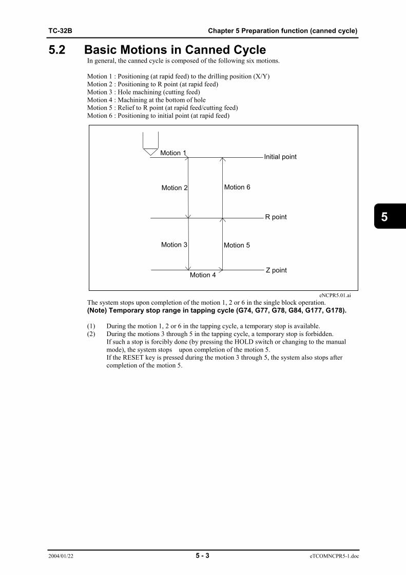
TC-32B Chapter 5 Preparation function (canned cycle)
2004/01/22 5 - 3 eTCOMNCPR5-1.doc
5
5.2 Basic Motions in Canned CycleIn general, the canned cycle is composed of the following six motions.
Motion 1 : Positioning (at rapid feed) to the drilling position (X/Y)Motion 2 : Positioning to R point (at rapid feed)Motion 3 : Hole machining (cutting feed)Motion 4 : Machining at the bottom of holeMotion 5 : Relief to R point (at rapid feed/cutting feed)Motion 6 : Positioning to initial point (at rapid feed)
eNCPR5.01.aiThe system stops upon completion of the motion 1, 2 or 6 in the single block operation.(Note) Temporary stop range in tapping cycle (G74, G77, G78, G84, G177, G178).
(1) During the motion 1, 2 or 6 in the tapping cycle, a temporary stop is available.(2) During the motions 3 through 5 in the tapping cycle, a temporary stop is forbidden.
If such a stop is forcibly done (by pressing the HOLD switch or changing to the manualmode), the system stops upon completion of the motion 5.If the RESET key is pressed during the motion 3 through 5, the system also stops aftercompletion of the motion 5.
Motion 1
Motion 2
Motion 3
Motion 4
Motion 5
Motion 6
Z point
R point
Initial point
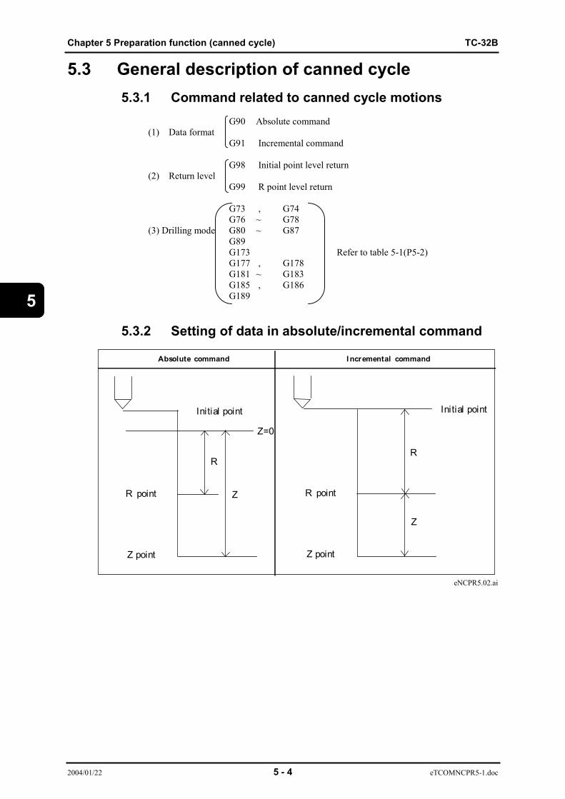
Chapter 5 Preparation function (canned cycle) TC-32B
2004/01/22 5 - 4 eTCOMNCPR5-1.doc
5
5.3 General description of canned cycle5.3.1 Command related to canned cycle motions G90 Absolute command
(1) Data formatG91 Incremental command
G98 Initial point level return
(2) Return levelG99 R point level return
G73 , G74G76 ~ G78
(3) Drilling mode G80 ~ G87G89G173 Refer to table 5-1(P5-2)G177 , G178G181 ~ G183G185 , G186G189
5.3.2 Setting of data in absolute/incremental command
eNCPR5.02.ai
Absolute command I ncremental command
Initial point
Z=0
Z
R
R point
Z point
Initial point
Z
R
R point
Z point

TC-32B Chapter 5 Preparation function (canned cycle)
2004/01/22 5 - 5 eTCOMNCPR5-1.doc
5
5.3.3 Types of return point (G98, G99)There are two types of return points - initial point level return (G98) and R point level return (G99)- when the canned cycle motions are finished.
eNCPR5.03.ai
(Note 1)G98 and G99 are modal commands. G98 is effective when the power is turned ON.(Note 2)If there is no Z-axis movement even if the tool length offset mode is selected, theinitial point is memorized without offset.(Note 3)The Z-axis machine coordinate value becomes the initial point when the cannedcycle cancel mode changes to the canned cycle mode.
5.3.4 Canned cycle motion conditionsThe canned cycle motions are available when the following commands are given.(1) The drilling mode (G73, G74, G76~G78, G81~G87, G89, G173, G177, G178, G181~G183,G185, G186, G189) command blocks contain any of X, Y, Z, R, A, B or C.(2) The blocks after the drilling mode command block through the canned cycle cancel blockcontain any of X, Y, Z, R, A, B or C.(Note)If there is no X, Y, Z, R, A, B or C in the block during the canned cycle, and thedrilling data other than those are commanded, the drilling data only are memorized.
I nitial point level return (G98) R point level return (G99)
Initial point
R point
Z point
R point
Z point

Chapter 5 Preparation function (canned cycle) TC-32B
2004/01/22 5 - 6 eTCOMNCPR5-1.doc
5
5.3.5 Machining data of canned cycleCommand format
G * * X _ Y _ Z _ R _ Q _ P _ F _ S _ K _ ;
G code G73, G74, G76~G78, G81~G87, G89, G173, G177, G178, G181~G183, G185,G186and G189.The G codes of the canned cycle are all modal.
X, Y : Drilling positon.The tool motion to the drilling position is done at a rapid feed.
Z : Bottom positionWhen the incremental mode is selected, the distance from the R point to the bottomof hole is specified.
R : R point position.When the incremental mode is selected, the distance fromthe point before the canned cycle becomes effective to theR point is specified.
Q : Cutting amount, shift amount, distance to feeding speed changeover point.(1) Each cutting amount commanded by G73, G83, G173 or G183.(2) Each cutting amount commanded by G77 or G78.(3) Each shift amount commanded by G76 or G87.(4) The distance to the feeding change point by G177or G178.(5) Orientation angle by G86, G186
P : Dwelling time. (The unit is the same as specified by G04.)
F : Cutting feedrate.
S : Spindle speed.
K : Repeat number of canned cycle.
G code Position data Machining data Repeat number
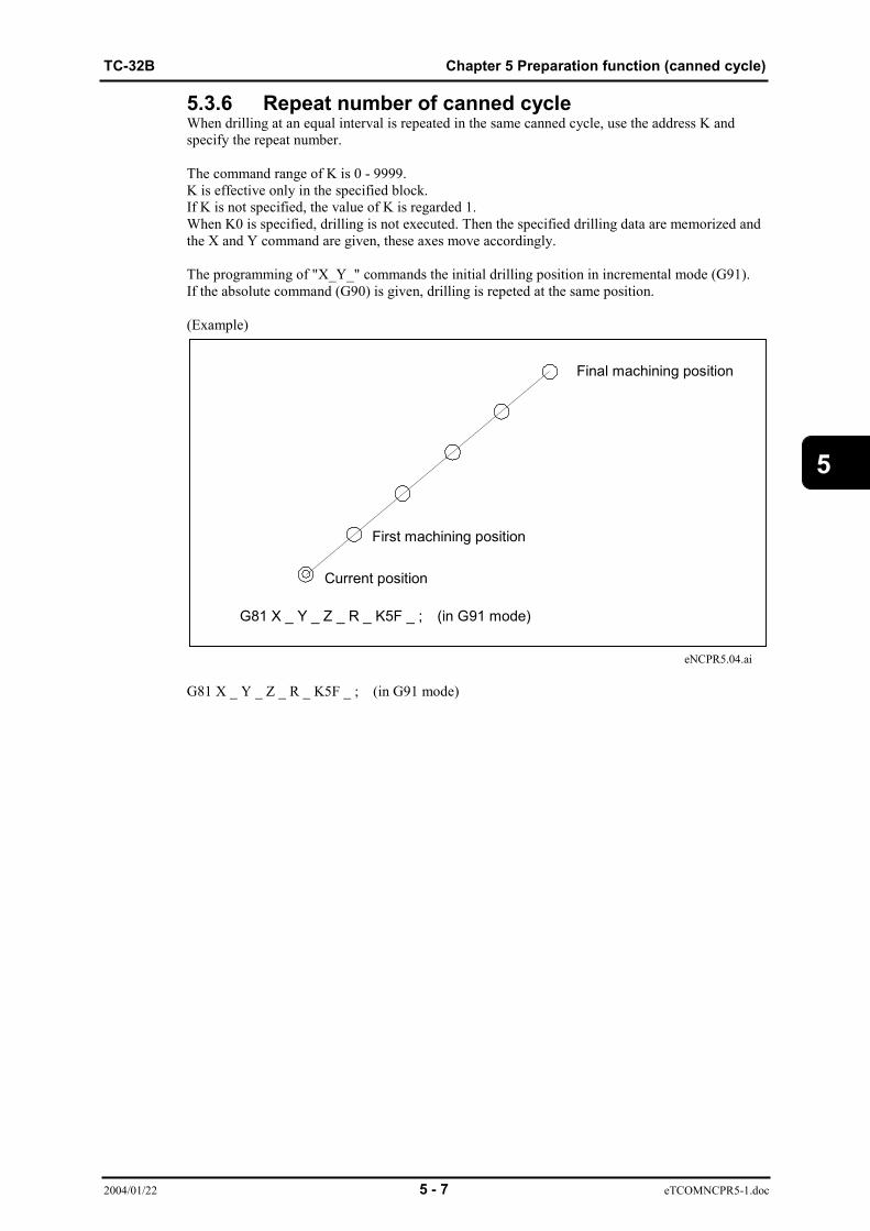
TC-32B Chapter 5 Preparation function (canned cycle)
2004/01/22 5 - 7 eTCOMNCPR5-1.doc
5
5.3.6 Repeat number of canned cycleWhen drilling at an equal interval is repeated in the same canned cycle, use the address K andspecify the repeat number.
The command range of K is 0 - 9999.K is effective only in the specified block.If K is not specified, the value of K is regarded 1.When K0 is specified, drilling is not executed. Then the specified drilling data are memorized andthe X and Y command are given, these axes move accordingly.
The programming of "X_Y_" commands the initial drilling position in incremental mode (G91).If the absolute command (G90) is given, drilling is repeted at the same position.
(Example)
eNCPR5.04.ai
G81 X _ Y _ Z _ R _ K5F _ ; (in G91 mode)
G81 X _ Y _ Z _ R _ K5F _ ; (in G91 mode)
Final machining position
First machining position
Current position
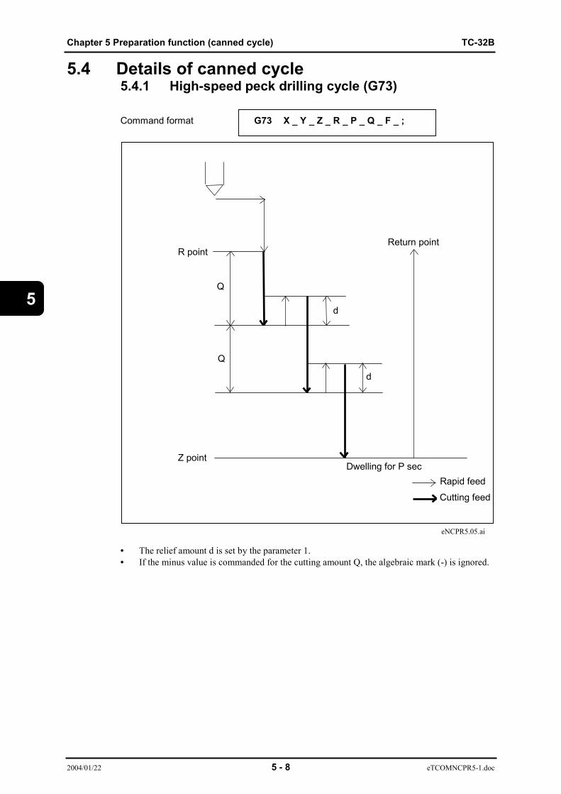
Chapter 5 Preparation function (canned cycle) TC-32B
2004/01/22 5 - 8 eTCOMNCPR5-1.doc
5
5.4 Details of canned cycle5.4.1 High-speed peck drilling cycle (G73)
Command format G73 X _ Y _ Z _ R _ P _ Q _ F _ ;
eNCPR5.05.ai
• The relief amount d is set by the parameter 1.• If the minus value is commanded for the cutting amount Q, the algebraic mark (-) is ignored.
R point
Z point
Q
Q
d
d
Dwelling for P sec
Return point
Rapid feed
Cutting feed

TC-32B Chapter 5 Preparation function (canned cycle)
2004/01/22 5 - 9 eTCOMNCPR5-1.doc
5
5.4.2 Reverse tapping cycle (G74)
Command format G74 X _ Y _ Z _ R _ P _ F _ S _ ;
eNCPR5.06.aiSpindle rotation stops at Z point.After dwelling for P sec, spindle rotates CW.
• When a temporary stop is applied on the way from the R point to the Z point or the R point,the tool stops after returning to the R point.
• If the address S exceeds the max, spindle speed in tapping, an alarm is generated.
Rapid feed
Cutting feed
Spindle CW
Spindle CCW
Return point
R point
Z point
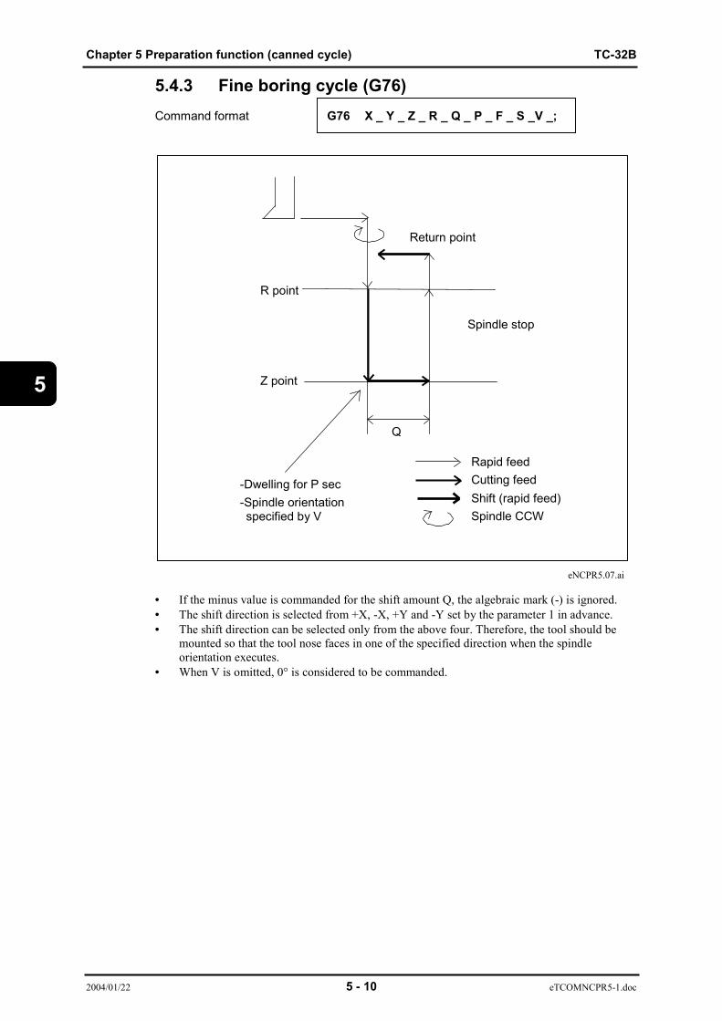
Chapter 5 Preparation function (canned cycle) TC-32B
2004/01/22 5 - 10 eTCOMNCPR5-1.doc
5
5.4.3 Fine boring cycle (G76)Command format G76 X _ Y _ Z _ R _ Q _ P _ F _ S _V _;
eNCPR5.07.ai
• If the minus value is commanded for the shift amount Q, the algebraic mark (-) is ignored.• The shift direction is selected from +X, -X, +Y and -Y set by the parameter 1 in advance.• The shift direction can be selected only from the above four. Therefore, the tool should be
mounted so that the tool nose faces in one of the specified direction when the spindleorientation executes.
• When V is omitted, 0° is considered to be commanded.
-Dwelling for P sec-Spindle orientation specified by V
R point
Z point
Return point
Spindle stop
Rapid feedCutting feedShift (rapid feed)Spindle CCW
Q

TC-32B Chapter 5 Preparation function (canned cycle)
2004/01/22 5 - 11 eTCOMNCPR5-1.doc
5
5.4.4 Tapping cycle (G77)
I_Command format G77 X _ Y _ Z _ R _ Q _ S _ ;
J_
eNCPR5.08.ai
• The relief amount d is set by the parameter 1.• If the minus value is commanded for the cutting amount Q, the algebraic mark (-) is ignored.• When a temporary stop is applied on the way from the R point to the Z point or the R point,
the tool stops after returning to the R point.• A thread pitch or number of threads should be specified.• Set the data on a thread pitch following the address I, and the data on a number of threads
following the address J.• If the address S exceeds the max, spindle speed in tapping, an alarm is generated.
rapid feedcutting feedspindle CWspindle CCW
R point
Z point
Q
Q
d
d
Return
Spindle stop

Chapter 5 Preparation function (canned cycle) TC-32B
2004/01/22 5 - 12 eTCOMNCPR5-1.doc
5
5.4.5 Reverse tapping cycle (synchro mode) (G78)I_
Command format G78 X _ Y _ Z _ R _ Q _ S _ ;J_
• When a temporary stop is applied on the way from the R point to the Z point or the R point,the tool stops after returning to the R point.
• A thread pitch or number of threads should be specified.Set the data on a thread pitch following the address “I”, and the data on a number of threadsfollowing the address “J”
• When I and J commanded the same block, movement follow the “I” command value.
• If the address S exceeds the max, spindle speed in tapping, an alarm is generated.
R point
Z point
Q
Q
d
d
Return
Spindle stop
rapid feed
cutting feedspindle CWspindle CCW
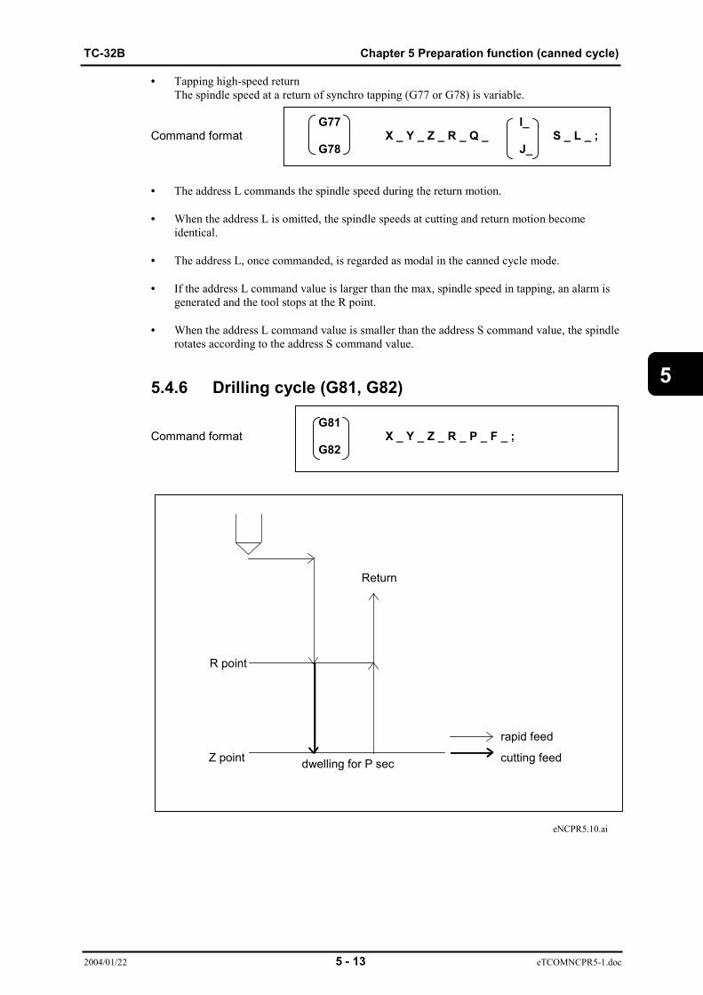
TC-32B Chapter 5 Preparation function (canned cycle)
2004/01/22 5 - 13 eTCOMNCPR5-1.doc
5
• Tapping high-speed returnThe spindle speed at a return of synchro tapping (G77 or G78) is variable.
G77 I_Command format X _ Y _ Z _ R _ Q _ S _ L _ ;
G78 J_
• The address L commands the spindle speed during the return motion.
• When the address L is omitted, the spindle speeds at cutting and return motion becomeidentical.
• The address L, once commanded, is regarded as modal in the canned cycle mode.
• If the address L command value is larger than the max, spindle speed in tapping, an alarm isgenerated and the tool stops at the R point.
• When the address L command value is smaller than the address S command value, the spindlerotates according to the address S command value.
5.4.6 Drilling cycle (G81, G82)
G81Command format X _ Y _ Z _ R _ P _ F _ ;
G82
eNCPR5.10.ai
R point
Z point
Return
dwelling for P sec
rapid feed
cutting feed

Chapter 5 Preparation function (canned cycle) TC-32B
2004/01/22 5 - 14 eTCOMNCPR5-1.doc
5
High speed cycleFeed speed at start and end of drilling cycle (G81 or G82) is variable.
G81Command format X _ Y _ Z _ R _ W _ V _ F _ E _ L _ P _;
G82
W : Speed changeover pointDistance from point "R", regardless of absolute mode (G90) or incrementalmode (G91)
E : Feed speed from point "R" to point specified by "W"V : Speed changeover point
Distance from point "Z", regardless of absolute mode (G90) or incrementalmode (G91)
L : Feed speed from point "Z" to point specified by "V"
eNCPR5.11.ai
dwelling for P sec rapid feedcutting feed
R point
Z point
Return
Feed speed E
Feed speed F
Feed speed L
W
V

TC-32B Chapter 5 Preparation function (canned cycle)
2004/01/22 5 - 15 eTCOMNCPR5-1.doc
5
5.4.7 Peck drilling cycle (G83)
Command format G83 X _ Y _ Z _ R _ P _ Q _ F _ ;
eNCPR5.12.ai
• The cutting start point d is set by the parameter.
• If the minus value is commanded for the cutting amount Q, the algebraic mark (-) is ignored.
R point
Z point
Q
Q
Return point
d
d
Dwelling for P sec
Rapid feedCutting feed

Chapter 5 Preparation function (canned cycle) TC-32B
2004/01/22 5 - 16 eTCOMNCPR5-1.doc
5
5.4.8 Tapping cycle (G84)
Command format G84 X _ Y _ Z _ R _ P _ F _ S _ ;
eNCPR5.13.ai
Spindle rotation stops at Z point.After dwelling for P sec, spindle rotates CW.
• When a temporary stop is applied on the way from the R point to the Z point or the R point,the tool stops after returning to the R point.
• If the address S exceeds the max, spindle speed in tapping, an alarm is generated.
rapid feedcutting feedspindle CWspindle CCW
R point
Z point
Return
Spindle stop

TC-32B Chapter 5 Preparation function (canned cycle)
2004/01/22 5 - 17 eTCOMNCPR5-1.doc
5
5.4.9 Boring cycle (G85, G89) G85
Command format X _ Y _ Z _ R_ P_ F_ ; G89
eNCPR5.14.ai
High speed cycleFree speed at return of boring cycle (G85 or G89) is variable.
G85Command format X _ Y _ Z _ R_ P_ F_ E_ P_ ;
G89
eNCPR5.15.ai
Rapid feedCutting feed
R point
Z point
Return point
Feed speed EFeed speed F
Dwelling for P sec
rapid feedcutting feedspindle CWspindle CCW
R point
Z point
Return
Spindle stop

Chapter 5 Preparation function (canned cycle) TC-32B
2004/01/22 5 - 18 eTCOMNCPR5-1.doc
5
5.4.10 Boring cycle (G86)
Command format G86 X _ Y _ Z _ R _ P _ F _ S_ Q_;
eNCPR5.16.ai
R point
Z point
Return point
Spindle stop(Q command omit)
Dwelling for P sec
Rapid feedCutting feedSpindle CW
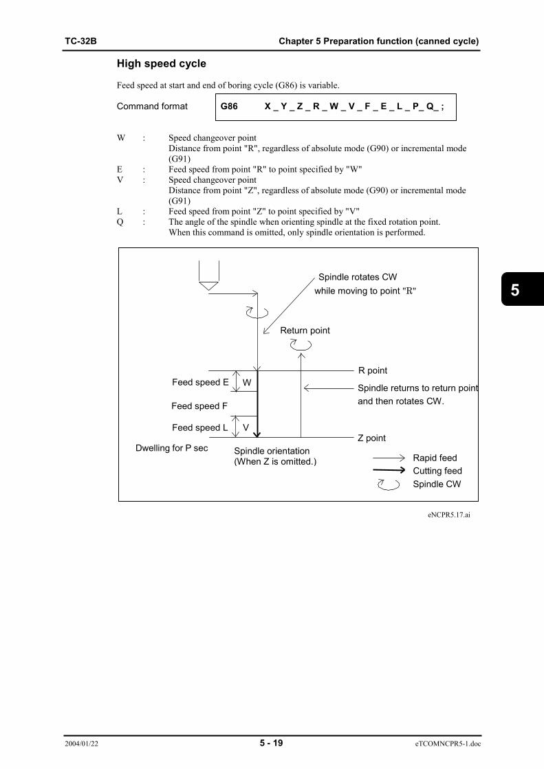
TC-32B Chapter 5 Preparation function (canned cycle)
2004/01/22 5 - 19 eTCOMNCPR5-1.doc
5
High speed cycle
Feed speed at start and end of boring cycle (G86) is variable.
Command format G86 X _ Y _ Z _ R _ W _ V _ F _ E _ L _ P_ Q_ ;
W : Speed changeover pointDistance from point "R", regardless of absolute mode (G90) or incremental mode(G91)
E : Feed speed from point "R" to point specified by "W"V : Speed changeover point
Distance from point "Z", regardless of absolute mode (G90) or incremental mode(G91)
L : Feed speed from point "Z" to point specified by "V"Q : The angle of the spindle when orienting spindle at the fixed rotation point.
When this command is omitted, only spindle orientation is performed.
eNCPR5.17.ai
5
Rapid feedCutting feedSpindle CW
R point
Z point
Return point
Feed speed E
Feed speed F
Feed speed L
W
V
Spindle orientation(When Z is omitted.)
Spindle rotates CWwhile moving to point "R"
Spindle returns to return pointand then rotates CW.
Dwelling for P sec

Chapter 5 Preparation function (canned cycle) TC-32B
2004/01/22 5 - 20 eTCOMNCPR5-1.doc
5
5.4.11 Back boring cycle (G87)Command format G87 X _ Y _ Z _ R _ Q _ P _ F _ S_ V_ ;
eNCPR5.18.ai
• If the minus value is commanded for the shift amount Q, the algebraic mark (-) is ignored.
• The shift direction is selected from +X, -X, +Y and -Y set by the parameter 1 in advance.
• The shift direction can be selected only from the above four. Therefore, the tool should bemounted so that the tool nose faces in one of the specified direction when the spindleorientation executes.
• G99 (R point level return) is unused.
• When V is omitted, 0° is considered to be commanded.
Rapid feedCutting feedShift (rapid feed)Spindle CWSpindle CCW
Spindle orientationspecified by V
R point
Z point
Dwelling for P sec
Single block stop
Q
Single block stop
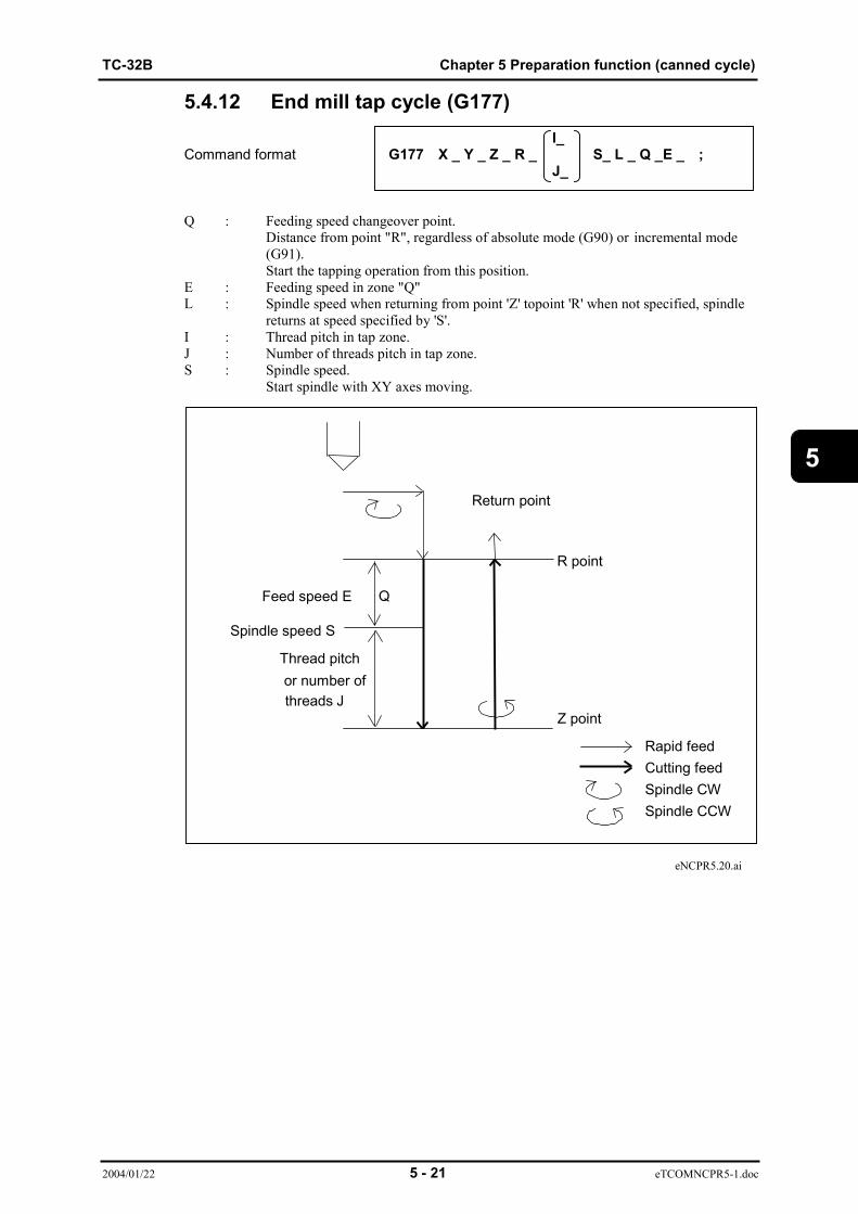
TC-32B Chapter 5 Preparation function (canned cycle)
2004/01/22 5 - 21 eTCOMNCPR5-1.doc
5
5.4.12 End mill tap cycle (G177)I_
Command format G177 X _ Y _ Z _ R _ S_ L _ Q _E _ ;J_
Q : Feeding speed changeover point.Distance from point "R", regardless of absolute mode (G90) or incremental mode(G91).Start the tapping operation from this position.
E : Feeding speed in zone "Q"L : Spindle speed when returning from point 'Z' topoint 'R' when not specified, spindle
returns at speed specified by 'S'.I : Thread pitch in tap zone.J : Number of threads pitch in tap zone.S : Spindle speed.
Start spindle with XY axes moving.
eNCPR5.20.ai
R point
Z point
Return point
Spindle speed S
Feed speed E
Thread pitchor number ofthreads J
Q
Rapid feedCutting feedSpindle CWSpindle CCW
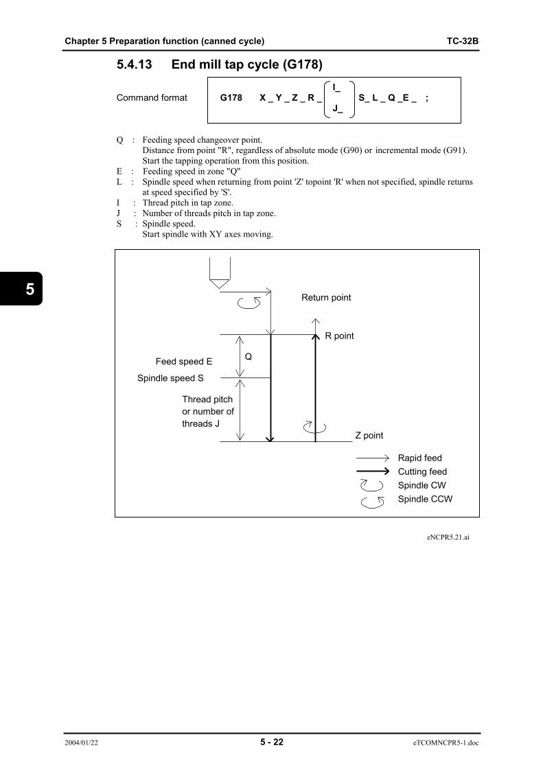
Chapter 5 Preparation function (canned cycle) TC-32B
2004/01/22 5 - 22 eTCOMNCPR5-1.doc
5
5.4.13 End mill tap cycle (G178) I_
Command format G178 X _ Y _ Z _ R _ S_ L _ Q _E _ ; J_
Q : Feeding speed changeover point.Distance from point "R", regardless of absolute mode (G90) or incremental mode (G91).Start the tapping operation from this position.
E : Feeding speed in zone "Q"L : Spindle speed when returning from point 'Z' topoint 'R' when not specified, spindle returns
at speed specified by 'S'.I : Thread pitch in tap zone.J : Number of threads pitch in tap zone.S : Spindle speed.
Start spindle with XY axes moving.
eNCPR5.21.ai
Rapid feedCutting feedSpindle CWSpindle CCW
R point
Z point
Return point
Spindle speed S
Feed speed E
Thread pitchor number ofthreads J
Q

TC-32B Chapter 5 Preparation function (canned cycle)
2004/01/22 5 - 23 eTCOMNCPR5-1.doc
5
5.4.14 Double drilling cycle (G181,G182)G181
Command format X _ Y _ Z _ R _ I _ J _ W _ V _ F _ E _ L _P_ ; G182
I : Double rapid feed start point (follow G90/G91)Distance from point "R" when incremental mode is specified
J : Double cutting feed start point (follow G90/G91)Distance from point "I" when incremental mode is specified
W: Speed changeover pointIncremental regardless of absolute mode (G90) or incremental mode (G91)
E : Feed speed within range specified by "W"V : Speed changeover point
Incremental regardless of absolute mode (G90) or incremental mode (G91)L : Feed speed within range specified by "V".
eNCPR5.22.ai
Rapid feedCutting feed
Z point
Return point
Feed speed E
Feed speed F
Feed speed L
W
V
R pointFeed speed E
Feed speed F
Feed speed L
W
V
rapid feedI point
J point
Dwelling for P sec
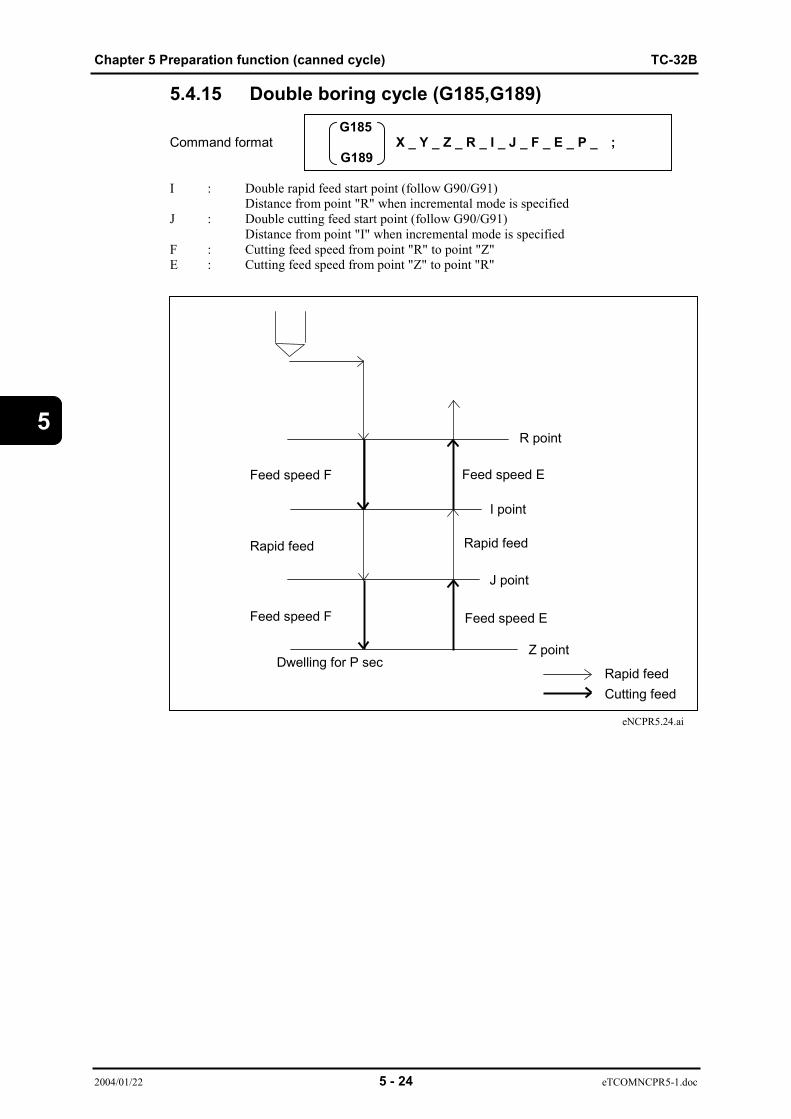
Chapter 5 Preparation function (canned cycle) TC-32B
2004/01/22 5 - 24 eTCOMNCPR5-1.doc
5
5.4.15 Double boring cycle (G185,G189)G185
Command format X _ Y _ Z _ R _ I _ J _ F _ E _ P _ ; G189
I : Double rapid feed start point (follow G90/G91)Distance from point "R" when incremental mode is specified
J : Double cutting feed start point (follow G90/G91)Distance from point "I" when incremental mode is specified
F : Cutting feed speed from point "R" to point "Z"E : Cutting feed speed from point "Z" to point "R"
eNCPR5.24.ai
Z point
Feed speed F
R point
Feed speed F
Rapid feed
I point
J point
Feed speed E
Feed speed E
Rapid feed
Rapid feedCutting feed
Dwelling for P sec
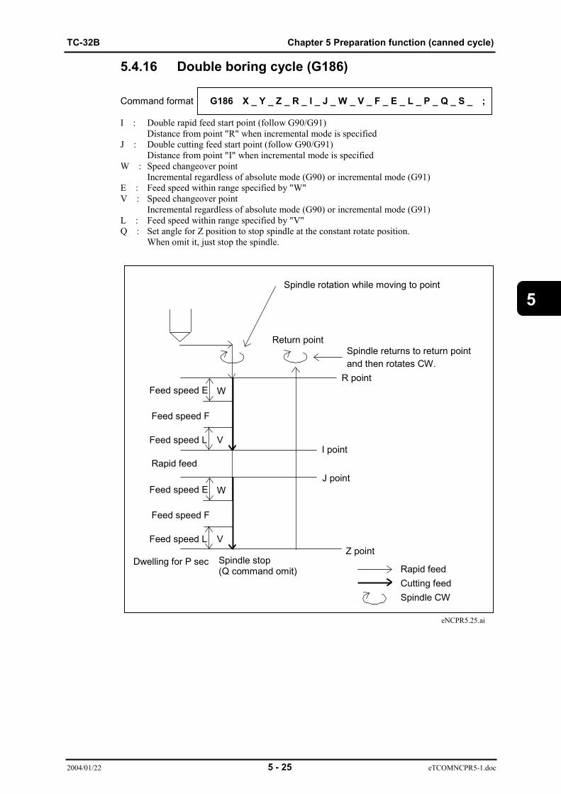
TC-32B Chapter 5 Preparation function (canned cycle)
2004/01/22 5 - 25 eTCOMNCPR5-1.doc
5
5.4.16 Double boring cycle (G186)
Command format G186 X _ Y _ Z _ R _ I _ J _ W _ V _ F _ E _ L _ P _ Q _ S _ ;
I : Double rapid feed start point (follow G90/G91)Distance from point "R" when incremental mode is specified
J : Double cutting feed start point (follow G90/G91)Distance from point "I" when incremental mode is specified
W : Speed changeover pointIncremental regardless of absolute mode (G90) or incremental mode (G91)
E : Feed speed within range specified by "W"V : Speed changeover point
Incremental regardless of absolute mode (G90) or incremental mode (G91)L : Feed speed within range specified by "V"Q : Set angle for Z position to stop spindle at the constant rotate position.
When omit it, just stop the spindle.
eNCPR5.25.ai
Rapid feedCutting feedSpindle CW
Z point
Return point
Feed speed E
Feed speed F
Feed speed L
W
V
R pointFeed speed E
Feed speed F
Feed speed L
W
V
Rapid feedI point
J point
Spindle returns to return pointand then rotates CW.
Spindle rotation while moving to point
Spindle stop(Q command omit)
Dwelling for P sec
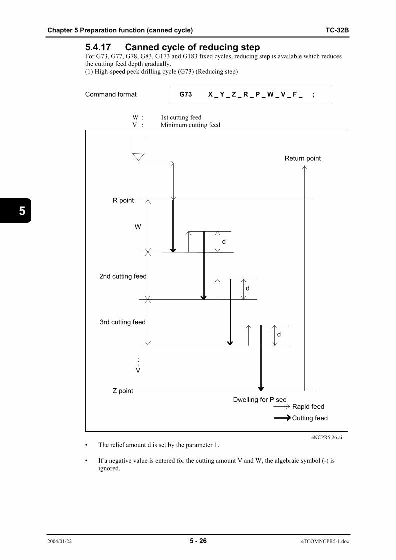
Chapter 5 Preparation function (canned cycle) TC-32B
2004/01/22 5 - 26 eTCOMNCPR5-1.doc
5
5.4.17 Canned cycle of reducing stepFor G73, G77, G78, G83, G173 and G183 fixed cycles, reducing step is available which reducesthe cutting feed depth gradually.(1) High-speed peck drilling cycle (G73) (Reducing step)
Command format G73 X _ Y _ Z _ R _ P _ W _ V _ F _ ;
W : 1st cutting feedV : Minimum cutting feed
eNCPR5.26.ai• The relief amount d is set by the parameter 1.
• If a negative value is entered for the cutting amount V and W, the algebraic symbol (-) isignored.
Rapid feed
Cutting feed
R point
Z point
d
d
d
Return point
Dwelling for P sec
W
3rd cutting feed
2nd cutting feed
...V

TC-32B Chapter 5 Preparation function (canned cycle)
2004/01/22 5 - 27 eTCOMNCPR5-1.doc
5
(2) Peck drilling cycle (G83) (Reducing step)
Command format G83 X _ Y _ Z _ R _ P _ W _ V _ F _ ;
W : 1st cutting feedV : Minimum cutting feed
eNCPR5.27.ai
• The relief amount d is set by the parameter 1.
• If a negative value is entered for the cutting amount V and W, the algebraic symbol (-) isignored.
Rapid feed
Cutting feed
3rd cutting feed
2nd cutting feed
R point
Z point
d
d
Return point
Dwelling for P sec
W
d
...V

Chapter 5 Preparation function (canned cycle) TC-32B
2004/01/22 5 - 28 eTCOMNCPR5-1.doc
5
(3) Tapping cycle (synchro mode)(G77) (Reducing step)
I_Command format G77 X _ Y _ Z _ R _ W _ V _ S;
J_
W : 1st cutting feedV : Minimum cutting feed
eNCPR5.28.ai• The relief amount d is set by the parameter 1.• If a negative value is entered for the cutting amount V and W, the algebraic symbol (-) is
ignored.• When a temporary stop is applied on the way from the R point to the Z point or the R point,• the tool stops after returning to the R point.• A thread pitch or number of threads should be specified.• Set the data on a thread pitch following the address I, and the data on a number of threads
following the address J.• If the address S exceeds the max, spindle speed in tapping, an alarm is generated.
Rapid feed
Cutting feedSpindle CWSpindle CCW
R point
Z point
d
d
d
Return point
W
Spindle stop
...V
3rd cutting feed
2nd cutting feed
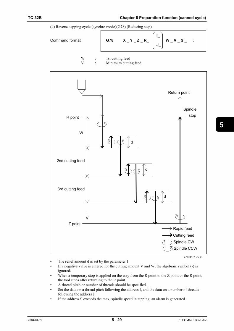
TC-32B Chapter 5 Preparation function (canned cycle)
2004/01/22 5 - 29 eTCOMNCPR5-1.doc
5
(4) Reverse tapping cycle (synchro mode)(G78) (Reducing step)
I_Command format G78 X _ Y _ Z _ R_ W _ V _ S _ ;
J_
W : 1st cutting feedV : Minimum cutting feed
eNCPR5.29.ai• The relief amount d is set by the parameter 1.• If a negative value is entered for the cutting amount V and W, the algebraic symbol (-) is
ignored.• When a temporary stop is applied on the way from the R point to the Z point or the R point,
the tool stops after returning to the R point.• A thread pitch or number of threads should be specified.• Set the data on a thread pitch following the address I, and the data on a number of threads
following the address J.• If the address S exceeds the max, spindle speed in tapping, an alarm is generated.
Rapid feed
Cutting feedSpindle CWSpindle CCW
R point
Z point
d
d
d
Return point
W
Spindlestop
...V
3rd cutting feed
2nd cutting feed

Chapter 5 Preparation function (canned cycle) TC-32B
2004/01/22 5 - 30 eTCOMNCPR5-1.doc
5
(5) High-speed peck drilling cycle (G173) (Reducing step)
Command format G173 X _ Y _ Z _ R _ W _ V _ F _ ;
W : 1st cutting feedV : Minimum cutting feed
eNCPR5.30.ai
• The relief amount d is set by the parameter 1.
• If a negative value is entered for the cutting amount V and W, the algebraic symbol(-) is ignored.
Rapid feedCutting feed
R point
Z point
d
d
d
W
...V
3rd cutting feed
2nd cutting feed
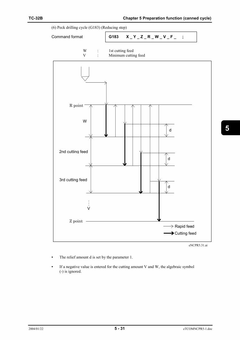
TC-32B Chapter 5 Preparation function (canned cycle)
2004/01/22 5 - 31 eTCOMNCPR5-1.doc
5
(6) Peck drilling cycle (G183) (Reducing step)
Command format G183 X _ Y _ Z _ R _ W _ V _ F _ ;
W : 1st cutting feedV : Minimum cutting feed
eNCPR5.31.ai
• The relief amount d is set by the parameter 1.
• If a negative value is entered for the cutting amount V and W, the algebraic symbol(-) is ignored.
3rd cutting feed
2nd cutting feed
R point
Z point
d
d
dwelling for P sec
W
d
...V
Rapid feed
Cutting feed

Chapter 5 Preparation function (canned cycle) TC-32B
2004/01/22 5 - 32 eTCOMNCPR5-1.doc
5
(7) For G73, G83, G173 and G183 fixed cycles, the cutting feed after the second time will be as below.Cutting feed depth = Coefficient × 1st cutting feed (W)
Time of cutting 2 3 4 5 6 7 8 9 10
Coefficient 0.825 0.675 0.525 0.425 0.35 0.3 0.225 0.175 0.15
11 12 13 14
0.1 0.1 0.075 0.075
• Coefficient of 14th cutting is applied to 15th cutting and after.• When the cutting feed has become smaller than the V value (minimum cutting feed),
the V value is applied for cutting.
(8) For G77 and G78 fixed cycles, the cutting feed after the second time will be as below.Cutting feed depth = Coefficient × 1st cutting feed (W)
Time of cutting 2 3 4 5 6 7 8 9 10
Coefficient 0.85 0.65 0.55 0.4 0.35 0.3 0.2 0.2 0.15
11 12 13 14
0.1 0.1 0.05 0.05
• Coefficient of 14th cutting is applied to 15th cutting and after.• When the cutting feed has become smaller than the V value (minimum cutting feed),
the V value is applied for cutting.
(Note 1) When switching between reducing step feed and fixed step feed, usethe W and Q commands.
(Note 2) When the W and Q commands are specified to the same block, the Wcommand has a priority.
(Note 3) When the W or Q command is not given, or 0 is given, cutting is carriedout once.When the V command is not given, or 0 is given, V=0.001 (metric) orV=0.0001(inch) is used.
5.4.18 Canned cycle cancel (G80)The canned cycle (G73, G74, G76 to G78, G81 to 87, G89, G177, G178, G181 to G182, G185,G186, G189) is cancelled and ordinary motion becomes effective afterwards.The R point, Z point, and other data on drilling are all cancelled.
Command format G80 ;
(Note 1) The canned cycle is cancelled not only by G80 but also by G00-G03. The tool change command G100 and M06 can cancel thecanned cycle after the tool change motion.
(Note 2) When the axis move command is given in the same block as G80, theaxis movement starts after the canned cycle is cancelled.

TC-32B Chapter 5 Preparation function (canned cycle)
2004/01/22 5 - 33 eTCOMNCPR5-1.doc
5
5.4.19 Notes on canned cycle(1) When commanding the canned cycle (G73, G81 to G83, G85, G89, G173,G181 to G183, G185,G189) which does not control the spindle rotation, the spindle should be rotated in advance by theM code.
(2) When the M code is commanded in the same block as the canned cycle, the M code is executedat the same time as the initial X/Y positioning or after that.When the repetition is specified by K code, the M code is executed only at the first time andnot executed any longer.
(3) When M00 or M01 is commanded in the same block as the canned cycle, the spindle andcoolant stop after the X/Y positioning and automatic resetting is not available.If resetting is necessary, command it in the manual operation mode or the MDI operation mode.
(4) When G00 to G03 are commanded in the same block as that of the canned cycle, the motionwill be as below.
G00 G81 X_ Y_ Z_ R_ P_ F_ ;In this case, the modal for G00 is updated and the canned cycle by G81 is executed.
G81 G00 X_ Y_ Z_ R_ P_ F_ ;In this case, X, Y, and Z axes move in accordance with G00 and the canned cycle is not executed.
(5) M200, M201, and M120 cannot be commanded in the same block as that of the canned cycle.

Chapter 5 Preparation function (canned cycle) TC-32B
2004/01/22 5 - 34 eTCOMNCPR5-1.doc
5
5.5 Canned cycle for tool change (non-stop ATC)(G100) (1) When TC-32B.
Command format G100 T _ X _ Y _ Z _ R _ A _ B _ L _ ;
eNCPR5.34.ai
T _ _ : Tool number.T1 _ _ : Pot number.T9 _ _ : Group number.A, B : Target value when moving A and B axes at in rapid feed
simultaneously with tool change motion.X,Y : Target value of movement (6) in rapid feed.Z : Target value of movement (7) in rapid feed.R : Retern position before tool change motion.
(Operated with tool length compensation applied)When "R" is not commanded, operation is performed using [ATCSYNCHRONOUS START POS] of USER PARAMETER 1 as "R" command value.
L : Specify the tool number, pot (magazine) number, and group number after “L” The pot with the corresponding tool attached is indexed by operation (4) after ATC. (Next tool preparation)
Single blockstop point
X ATCposition
X origin position
Y ATCposition
XY axes
(2) (3)
(4)
(6) (5)
ATCposition
R point
(1)
(2)
(3) (4)
(7)
Z axis direction
(5)

TC-32B Chapter 5 Preparation function (canned cycle)
2004/01/22 5 - 35 eTCOMNCPR5-1.doc
5
Operations(1) Tool moves to the Z-axis point "R" while performing 0-degree spindle orientation. When "T" is commanded, magazine swivels.(2) Tool movement to theZ-axis ATC origin, to the X axis origin point and to Y axis ATC position, A, B axes movement to the the commanded value and also maga zine cover opening occur simultaneously.(3) Tool moves to theX-axis ATC position.(4) Arm swivels to change tool. Tool change motion differs depending on setting on [MAGAZINE TOOL] screen. Refer to the "Tool Change Motion" for detailes.(5) Tool movement to the X axis orgin point and Z axis point "R" and magazine cover closing occurs stimultaneously.(6) XY axes moves to the commanded value.(7) Tool moves to Z-axis commanded position.
Caution• When performing cycle operation, tool moves in cutting mode between
operations (1) and (6). And tool moves in position check mode.For XY positioning at operation (2) and (3) ( from X:origin Y: ATC position to Xaxis positioning (ATC position)) ,tool moves in cutting mode when Y axispositions at the ATC position before X axis does.
• When [RESET] key or [STOP SWITCH] key is pressed at operations (2) ,machine stops after Z axis movement to ATC origin point.For X, Y, A, and B axes movement, machine stops immediately.
• When [RESET] key or [STOP SWITCH] key is pressed between operations (3)and (5) , machine stops after motion (5) is completed.For the operation (2), A, and B axes movement, machine stops immediately.
• Machine does not stop if single block occurs between operations (1) and (6).
• For operation (5), machine goes to the next opeation after closing the magazinecover without checking if the magazine cover is closed.
• Mode can not be switched between operation (2) and (6).
• All data other than G100 can be omitted. However, code "T" must becommanded once by operator before G100 is commanded.
• Tool offset is canceled when G100 is commanded.Further, tool length compensation is canceled from operation (2).
• When tool offset (G41 or G42) and X and Y axes movement are commanded toblock G100, tool offset begins when X and Y axes movement (6) commences.Start-up is performed in format 1, regardless of parameters.
• When tool offset is commanded to block G100, tool offset becomes valid fromoperation (5) .
• When G100 is commanded while tool length compensation (G49) is canceled,operation (1) is performed subject to [ATC REFERENCE TOOL LENGTH]selection for user parameter.When tool offset is not commanded to block G100, operations (5) are performedsubject to [ATC REFERENCE TOOL LENGTH] selection for user parameter.
• Alarm appears when code M other than spindle command is commanded toblock G100.Alarm appears when axis A or B is commanded while optional A and B axes arenot in use.
Chapter 5 Preparation function (canned cycle) TC-32B
2004/01/22 5 - 36 eTCOMNCPR5-1.doc
5
• When point "R" command position (5) is lower than Z axis command position(7), tool moves to Z-axis commanded position, and operation (7) is notperformed.
Tool change motionTool change motion differs depending on tool type set on [MAGAZINE TOOL] screen.
(When large tool is not set on [MAGAZINE TOOL])
The following sequence is performed:(1) Pot raises.(2) Magazine swivels.(3) Pot lowers.(4) Arm swivels at high speed.
(When large tool is set on [MAGAZINE TOOL])
Tool change from standard tool to standard tool, and large tool to large tool.
The following sequence is performed:(1) Pot raises.(2) Magazine swivels.(3) Pot lowers.(4) Arm swivels.(5) Pot raises.
When pot is already at upper limit before tool change motion commences, sequence starts from(2).
When ((4) arm swivels) changing from large tool to large tool, arm swivels at low speed.When ((4) arm swivels) changing from standard tool to standard tool, arm swivels at high speed.
Tool change from large tool to standard tool or vice versa.
The following sequence is performed:(1) Pot raises.(2) Magazine swivels. (Empty pot is indexed.)(3) Pot lowers.(4) Arm swivels.(5) Pot raises.(6) Magazine swivels. (Specified pot is indexed.)(7) Pot lowers.(8) Arm swivels.(9) Pot raises.
When pot is already at upper or lower limit before tool change motion commences, sequence startsfrom (3) or (4), respectively.
For operation (2), empty pot is indexed appropriately for large tool and standard tool.
Arm swivels ((4) or (8)) at low speed when large tool is to be changed, and at high speed whenstandard tool is to be changed.
(Note1) If empty pot for large tool is not available when change from large toolto standard tool is attempted, [*NO EMPTY POT] alarm appears.
(Note2) If empty pot for standard tool is not available when change fromstandard tool to large tool is attempted, [*NO EMPTY POT] alarmappears.

TC-32B Chapter 5 Preparation function (canned cycle)
2004/01/22 5 - 37 eTCOMNCPR5-1.doc
5
Next tool preparationNext tool preparation is performed after the arm has swiveled or the pot has risen after the armswivels in the ATC sequence.When ATC is not performed, only next tool preparation is performed.Next tool preparation is not performed when the next tool is already indexed.
The next tool preparation sequence differs depending on the type of tool set on the magazine toolscreen.
When large tool is not set on [MAGAZINE TOOL](1) Pot rises(2) Magazine swivels(3) Pot lowersNext tool preparation ends when the above sequence is completed.The sequence starts from (2) when the pot is already at the upper limit before next tool preparationcommences.
When large tool is set on [MAGAZINE TOOL]Both spindle tool and next tool are standard or large(1) Pot rises(2) Magazine swivels(3) Pot lowersNext tool preparation ends when the above sequence is completed.The sequence starts from (2) when the pot is already at the upper limit before next tool preparationcommences.
Spindle tool is standard and next tool is large or vice versa(1) Pot rises(2) Magazine swivels (empty pot is indexed)(3) Pot lowersNext tool preparation ends when the above sequence is completed.The sequence starts from (2) when the pot is already at the upper limit before next tool preparationcommences.
(Note 1) When the next tool is changed from a large tool to a standard tool andthere is no empty pot for a large tool, the [NO EMPTY POT] error occurs.
(Note 2) When the next tool is changed from a standard tool to a large tool and there is no empty pot for a standard tool, the [NO EMPTY POT] error occurs.

Chapter 5 Preparation function (canned cycle) TC-32B
2004/01/22 5 - 38 eTCOMNCPR5-1.doc
5
(This page is a blank.)

TC-32B Chapter6 Preparation function (coordinate calculation)
2004/01/22 6 - 1 eTCOMNCPR6-1.doc
6
CHAPTER 6
PREPARATION FUNCTION (COORDINATE CALCULATION)
6.1 List of coordinate calculation function6.2 Coordinate calculation parameter6.3 Details of coordinate calculation function6.4 Usage of coordinate calculation function

Chapter6 Preparation function (coordinate calculation) TC-32B
2004/01/22 6 - 2 eTCOMNCPR6-1.doc
6
6 Coordinate calculation functionThis function is for calculating the point group coordinates in one block.Point groups are such as on a linear line, on a grid and on a circular arc.By combining such functions as the canned cycle etc., drilling at each point group is available byone command.
6.1 List of Coordinate Calculation FunctionTable 6-1 List of coordinate calculation function
G code Name Function
G36 Bolt hole circle Coordinate calculation of point group oncircular arc.
G37 Linear (angle) Coordinate calculation of point group on linearline by angle designation.
G38 Linear (X,Y) Coordinate calculation of point group of linearline by coordinate designation.
G39 Grid Coordinate calculation of point group on grid.
6.2 Coordinate Calculation ParameterCommand format G36
·· X_Y_I_J_K_P_Q_ ;.
G39
X,Y: Reference point of coordinate calculationI,J,K,P,Q: Coordinate calculation parameter
(1) Reference point coordinate (X,Y)This should be commanded by the working coordinate system.When this is omitted, the current position becomes the reference point.
(2) Coordinate calculation parameter (I,J,K,P,Q)This should be commanded in the same block as the G36~G39.This parameter is effective only in the block, and automatically cleared after calculation isfinished.
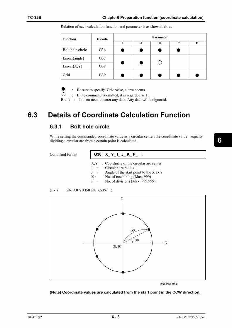
TC-32B Chapter6 Preparation function (coordinate calculation)
2004/01/22 6 - 3 eTCOMNCPR6-1.doc
6
Relation of each calculation function and parameter is as shown below.
ParameterFunction G codeI J K P Q
Bolt hole circle G36 ● ● ● ●Linear(angle) G37
Linear(X,Y) G38● ●
Grid G39 ● ● ● ● ●
● : Be sure to specify. Otherwise, alarm occurs.: If the command is omitted, it is regarded as 1.
Brank : It is no need to enter any data. Any data will be ignored.
6.3 Details of Coordinate Calculation Function6.3.1 Bolt hole circleWhile setting the commanded coordinate value as a circular center, the coordinate value equallydividing a circular arc from a certain point is calculated.
Command format G36 X_ Y_ I_ J_ K_ P_ ;
X,Y : Coordinate of the circular arc centerI : Circular arc radiusJ : Angle of the start point to the X axisK : No. of machining (Max. 999)P : No. of divisions (Max. 999.999)
(Ex.) G36 X0 Y0 I50 J30 K5 P6 ;
eNCPR6.05.ai
(Note) Coordinate values are calculated from the start point in the CCW direction.

Chapter6 Preparation function (coordinate calculation) TC-32B
2004/01/22 6 - 4 eTCOMNCPR6-1.doc
6
6.3.2 Linear (angle)With the reference point at the commanded coordinate, the coordinate values along the linear lineat the angle (θ°) formed by the X axis are calculated.
Command format G37 X_ Y_ I_ J_ K_ ;
X,Y: Coordinate of reference pointI : Interval between machning pointsJ : Angle intersecting the X axisK : No. of machining (Max. 999)
eNCPR6.01.ai(Note 1) When K is omitted, it is regarded as 1.(Note 2) The reference point becomes the first machining point.
6.3.3 Linear (X, Y)With the reference point at the commanded coordinate, the coordinate values added in the X andY directions respectively are calculated.
Command format G38 X_ Y_ I_ J_ K_ ;
X,Y : Coordinate of reference pointI : Interval on the X axisJ : Interval on the Y axisK : No. of machining (Max. 999)

TC-32B Chapter6 Preparation function (coordinate calculation)
2004/01/22 6 - 5 eTCOMNCPR6-1.doc
6
(Ex.) G38 X0 Y0 I20 J15 K4 ;
eNCPR6.02.ai
(Note 1) When K is omitted, it is regarded as 1.(Note 2) The reference point becomes the first machining point.
6.3.4 GridWith the reference point at the commanded coordinate, the coordinate values of the gridcomposed of points arranged at an even interval and parallel to both the X-axis and the verticalaxis are calculated.By specifying an angle to the X axis, the total form can be inclined.
Command format G39 X_ Y_ I_ J_ K_ P_ Q_ ;
X,Y : Coordinate of reference pointI : Interval on the X axisJ : Interval on the Y axisK : No. of machining point in the X direction (Max. 999)P : No. of machining point in the Y direction (Max. 999)Q : Angle intersecting the X axis
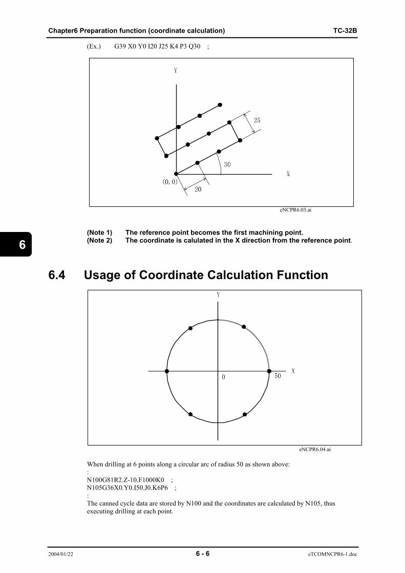
Chapter6 Preparation function (coordinate calculation) TC-32B
2004/01/22 6 - 6 eTCOMNCPR6-1.doc
6
(Ex.) G39 X0 Y0 I20 J25 K4 P3 Q30 ;
eNCPR6.03.ai
(Note 1) The reference point becomes the first machining point.(Note 2) The coordinate is calulated in the X direction from the reference point.
6.4 Usage of Coordinate Calculation Function
eNCPR6.04.ai
When drilling at 6 points along a circular arc of radius 50 as shown above::N100G81R2.Z-10.F1000K0 ;N105G36X0.Y0.I50.J0.K6P6 ;:The canned cycle data are stored by N100 and the coordinates are calculated by N105, thusexecuting drilling at each point.

TC-32B Chapter 7 Macro
2004/01/22 7 - 1 eTCOMNCPR7-1.doc
7
CHAPTER 7
MACRO
7.1 What is a Macro?7.2 Variable Function7.3 Calculation Function7.4 Control Function7.5 Call Function

Chapter 7 Macro TC-32B
2004/01/22 7 - 2 eTCOMNCPR7-1.doc
7
7.1 What is a Macro?A “macro” has four main functions: variable function, calculation function, control function(condition branch), and call function (performs the same operation repeatedly). Using thesemacro functions allows you to create original canned cycles or more flexible programs.Details of these functions are explained in the following sections:7.2 Variable function7.3 Calculation function7.4 Control function7.5 Call functionExamples of how these functions are combined are shown below in example 1 and on thefollowing page in example 2.The program creation procedure will be explained in the subsequent sections.
e.g.1 Tool breakage detection is performed once when machine program has been executed ten times.
N01G90G0G54. . . . .;N02;[WORKING PROGRAM]
N50#100=#100+1 ; (Count up)N511IF[#100LT10] GOTO 55 ;
(Proceeds to N55 when contents of #100 are less than 10)N53M200; (Tool breakage detection)N54#100=0 ; (Counter reset)N55M30 ;
e.g.2 Program that performs arc cutting by designating center, radius, and angle.
X: CENTER X Y: CENTER Y R: RADIUS Z: CUT POS ZW: STOP BEFORE WORK U: CUT START ANGLEV: CUT END ANGLE F: FEEDRATE
Main program
N01G90G54G0Z30. ;N02G65P0042X-100. Y-100. R50. Z-3.W2. UO. V30. F1000;
Macro program O0042
N01 G90G0X[#24+COS[#21]*#18]Y[#25+SIN[#21]*#18];N02 Z#23;N03 G1Z#26F#9;N03 G3X[#24+COS[#22]*#18]Y[#25+SIN[#22]*#18 R#18;N04 G0Z#23;N05 M99;
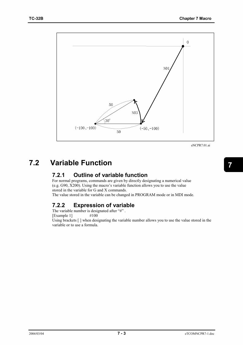
TC-32B Chapter 7 Macro
2004/03/04 7 - 3 eTCOMNCPR7-1.doc
7
eNCPR7.01.ai
7.2 Variable Function7.2.1 Outline of variable functionFor normal programs, commands are given by directly designating a numerical value(e.g. G90, X200). Using the macro’s variable function allows you to use the valuestored in the variable for G and X commands.The value stored in the variable can be changed in PROGRAM mode or in MDI mode.
7.2.2 Expression of variableThe variable number is designated after “#” .[Example 1] #100Using brackets [ ] when designating the variable number allows you to use the value stored in thevariable or to use a formula.

Chapter 7 Macro TC-32B
2004/01/22 7 - 4 eTCOMNCPR7-1.doc
7
[Example 2] #100 = #[100+10]This formula specifies that the value stored in variable #110 iswritten to #100.
[Example 3] When #1 = 9, #9 = 20, and #20 = 30,#5 = # [# [#1]] is equal to #5 = 30.A variable can be used instead of designating a numerical value.
[Example 4] #3=#2+10;G01X#3Y10;This formula specifies the X coordinate as the value stored invariable 2 with 10 added to it. (If #2 is 40, X#3 is 50.)When a variable is used as address data as shown in example 4, however, the valuesbelow the significant digits used as address data are rounded off.Note that an alarm will occur if the value rounded off to the nearest significant digitexceeds the maximum address command value.[Example] Assume that the G00X#1; command is used for a machine with asignificant digit setting of 1/1000.When #1 is 12.345678, the command format will be G00X12.346.Variable cannot be quoted in address N.
[Example 5] N#20 cannot be used.
7.2.3 Undefined variableWhen the value of the variable is not defined, it is called a “NULL” variable.#0 is always a “NULL” variable. This can be read but cannot be write.
e.g.1 When #1 is <Blank>.G01X#1Y100. → G01Y100.G01X [1+10. ]Y100. → G01X10. Y100.
e.g.2 Calculation#0 + #0 → 0#0*5 → 0
e.g.3 Condition formula
When #1 is <Blank> When #1 is 0 (zero)
#1 EQ #0 → Established#1 NE 0 → Established#1 GE #0 → Established#1 GT 0 → Not established
#1 EQ #0 → Not established#1 NE 0 → Not established#1 GE #0 → Established#1 GT 0 → Not established
For EQ and NE, <Blank> is considered not equal to 0 (zero).
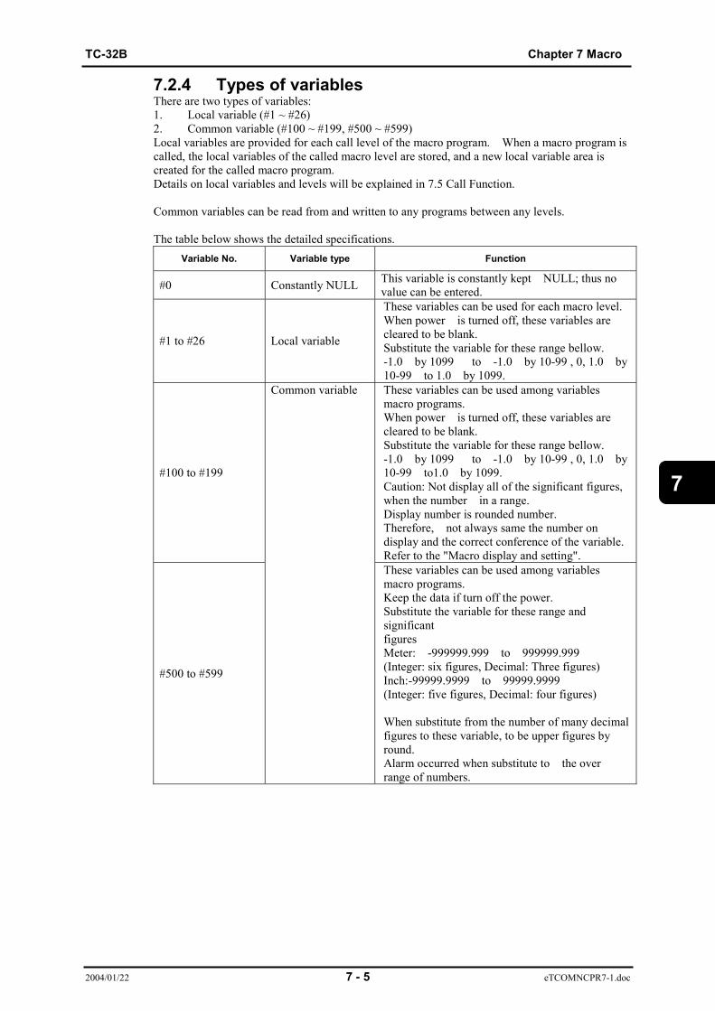
TC-32B Chapter 7 Macro
2004/01/22 7 - 5 eTCOMNCPR7-1.doc
7
7.2.4 Types of variablesThere are two types of variables:1. Local variable (#1 ~ #26)2. Common variable (#100 ~ #199, #500 ~ #599)Local variables are provided for each call level of the macro program. When a macro program iscalled, the local variables of the called macro level are stored, and a new local variable area iscreated for the called macro program.Details on local variables and levels will be explained in 7.5 Call Function.
Common variables can be read from and written to any programs between any levels.
The table below shows the detailed specifications.Variable No. Variable type Function
#0 Constantly NULL This variable is constantly kept NULL; thus novalue can be entered.
#1 to #26 Local variable
These variables can be used for each macro level.When power is turned off, these variables arecleared to be blank.Substitute the variable for these range bellow.-1.0 by 1099 to -1.0 by 10-99 , 0, 1.0 by10-99 to 1.0 by 1099.
#100 to #199
These variables can be used among variablesmacro programs.When power is turned off, these variables arecleared to be blank.Substitute the variable for these range bellow.-1.0 by 1099 to -1.0 by 10-99 , 0, 1.0 by10-99 to1.0 by 1099.Caution: Not display all of the significant figures,when the number in a range.Display number is rounded number.Therefore, not always same the number ondisplay and the correct conference of the variable.Refer to the "Macro display and setting".
#500 to #599
Common variable
These variables can be used among variablesmacro programs.Keep the data if turn off the power.Substitute the variable for these range andsignificantfiguresMeter: -999999.999 to 999999.999(Integer: six figures, Decimal: Three figures)Inch:-99999.9999 to 99999.9999(Integer: five figures, Decimal: four figures)
When substitute from the number of many decimalfigures to these variable, to be upper figures byround.Alarm occurred when substitute to the overrange of numbers.
Chapter 7 Macro TC-32B
2004/01/22 7 - 6 eTCOMNCPR7-1.doc
7
7.2.5 Variable display and settingVariables are displayed and manually set on the data bank screen.Press the [3] and [ENT] keys at the data bank menu screen, or shift the cursor to the menu No.3and press the [ENT] key. The following items are displayed on the screen.
Common variables (#100~#199, #500~#999) and local variables can be referred to or changed.
Number displayNumbers are displayed only when value of common variables for #100 to #199 or local variablesis in a range bellow.The display changes to [***********], if not in a range.
Meter:-999999.999 to 999999.999(Integer: six figures, Decimal: three figures)
Inch:-99999.9999 to 99999.9999(Integer: five figures, Decimal: four figures)
Not display all of the significant figures, when the number in a range.Display number is rounded number.Therefore, not always same the number on display and the correct conference of the variable.
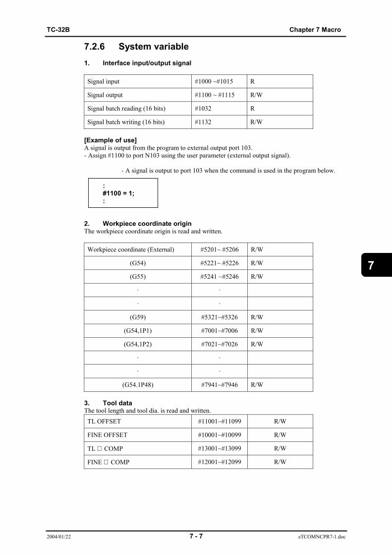
TC-32B Chapter 7 Macro
2004/01/22 7 - 7 eTCOMNCPR7-1.doc
7
7.2.6 System variable1. Interface input/output signal
Signal input #1000 ~#1015 R
Signal output #1100 ~ #1115 R/W
Signal batch reading (16 bits) #1032 R
Signal batch writing (16 bits) #1132 R/W
[Example of use]A signal is output from the program to external output port 103.- Assign #1100 to port N103 using the user parameter (external output signal).
- A signal is output to port 103 when the command is used in the program below.
:#1100 = 1;:
2. Workpiece coordinate originThe workpiece coordinate origin is read and written.
Workpiece coordinate (External) #5201~ #5206 R/W
(G54) #5221~ #5226 R/W
(G55) #5241 ~#5246 R/W
· ·
· ·
(G59) #5321~#5326 R/W
(G54,1P1) #7001~#7006 R/W
(G54,1P2) #7021~#7026 R/W
· ·
· ·
(G54.1P48) #7941~#7946 R/W
3. Tool dataThe tool length and tool dia. is read and written.TL OFFSET #11001~#11099 R/W
FINE OFFSET #10001~#10099 R/W
TL ∅ COMP #13001~#13099 R/W
FINE ∅ COMP #12001~#12099 R/W

Chapter 7 Macro TC-32B
2004/01/22 7 - 8 eTCOMNCPR7-1.doc
7
4. Alarm indication#3000 = n (ALARM MESSAGE)Alarm number 9000 + n (n: 0 ~200) occurs, and the alarm message in the brackets (the first 20characters, reset by the [RESET] key) is displayed.Only alphanumerical characters are used in the brackets and registered in the alarm log.[Example of use]When the following block is executed:#3000 = 6 (ABCD);“9006 *ABCD” alarm occurs.(Note) Command during tool radius compensation, feed to the position that
offset vector standing position be vertical to feed directin before.
5. Message display and stop#3006 = (MESSAGE)After execution of the previous block is stopped, a message up to 20 characters is displayed inbrackets. When the message contains 21 characters or more, only the first 20 characters aredisplayed.The alarm number is fixed at 9300 (stop level 1, reset level 1).(Note) Command during tool radius compensation, feed to the position that
offset vector standing position be vertical to feed directin before.
6. TimeTime 1 #3001 R/W This timer counts the operation time in
increments of 10 msec.The timer is reset to zero when the counted timereaches 42949672.96 seconds (approx. 497 days)or when power is turned on.After resetting to zero, it starts counting.
Time 2 #3002 R/W This timer counts the time when the start LED islit (STL) in increments of 10 msec.The timer is reset to zero when the counted timereaches 42949672.96 seconds (approx. 497 days).The value is stored even when the power isturned off.
7. Operation controlOperation
control#3003 R/W MFIN
0: WAIT2: NOT WAIT
Operationcontrol
#3004 R/W FEED OVERRIDE EXACT STOP0: VALID2: INVALID
#3003- “0” is set when power is turned on.- “0” is set when the [RESET] button is pressed or M30 is used.- When MFIN is set to [NOT WAIT], the program proceeds to the next block withoutwaiting for MFIN. In addition, MFIN is not confirmed to be OFF before the M signal is output.- When MFIN is set to [NOT WAIT], the next M signal is output after the time set for [EXTSIGNAL OUTPUT TIME (MFIN OFF)] (user parameter - switch 1) has elapsed.
#3004- “0” is set when power is turned on.- “0” is set when the [RESET] button is pressed or M30 is used.- When [SPINDLE OVERRIDE] is set to [INVALID], override is fixed at 100%, regardlessof the position of the [OVERRIDE] switch on the operation panel.- Spindle override and rapid feed override are also fixed at 100%.
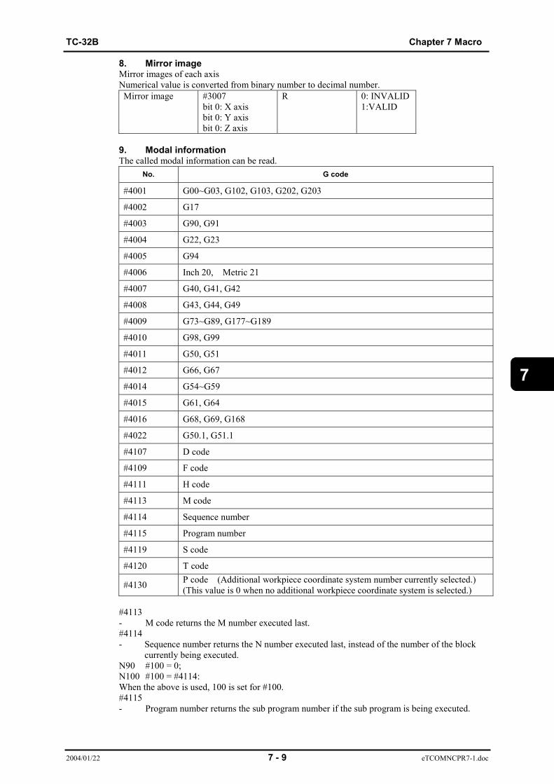
TC-32B Chapter 7 Macro
2004/01/22 7 - 9 eTCOMNCPR7-1.doc
7
8. Mirror imageMirror images of each axisNumerical value is converted from binary number to decimal number.Mirror image #3007
bit 0: X axisbit 0: Y axisbit 0: Z axis
R 0: INVALID1:VALID
9. Modal informationThe called modal information can be read.
No. G code
#4001 G00~G03, G102, G103, G202, G203
#4002 G17
#4003 G90, G91
#4004 G22, G23
#4005 G94
#4006 Inch 20, Metric 21
#4007 G40, G41, G42
#4008 G43, G44, G49
#4009 G73~G89, G177~G189
#4010 G98, G99
#4011 G50, G51
#4012 G66, G67
#4014 G54~G59
#4015 G61, G64
#4016 G68, G69, G168
#4022 G50.1, G51.1
#4107 D code
#4109 F code
#4111 H code
#4113 M code
#4114 Sequence number
#4115 Program number
#4119 S code
#4120 T code
#4130 P code (Additional workpiece coordinate system number currently selected.)(This value is 0 when no additional workpiece coordinate system is selected.)
#4113- M code returns the M number executed last.#4114- Sequence number returns the N number executed last, instead of the number of the block
currently being executed.N90 #100 = 0;N100 #100 = #4114:When the above is used, 100 is set for #100.#4115- Program number returns the sub program number if the sub program is being executed.

Chapter 7 Macro TC-32B
2004/01/22 7 - 10 eTCOMNCPR7-1.doc
7
10. Current positionNo. Contents Coordinate System Tool offset Read while
traveling#5001~#5008
End pointcoordinate
Workpiece coordinatesystem Not included Possible
#5021~#5028
Currentposition
Machine coordinatesystem Included Not possible
#5041~#5048
Currentposition
Workpiece coordinatesystem Included Not possible
#5061~#5068
Skipcoordinate
Workpiece coordinatesystem Included Possible
#5081~#5088
Tool lengthoffset Not possible
#5101~#5108
Servodeviation Not possible
#5201~#5208
Externalworkpiececoordinate zero
“Not possible” is listed in the “Read while traveling “column for “Current position” tool lengthoffset” and “servo deviation”. This means that the value is not guaranteed because the value is setwhen “Interpretation” is performed.In the program below, the macro command is executed in the block during interpretation while theaxis travel block is being executed, so the position during travel is read, instead of the positiontraveled to in the previous block.X-10.;X-10.;X-10.;#100=#5021;
11. ATC toolRead the tool number that set to the ATC tool screen.#3700 Spindle R
#3701 Pot 1 R
#3702 Pot 2 R
. . R
. . R
#3750 Pot 50 R0 : Cap is specified.1~99 : Tool number set by NC language mode.1001~1099 : Tool number set by conversation modeBlank : Non setting
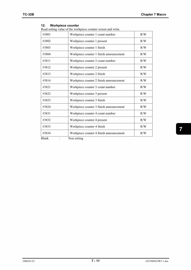
TC-32B Chapter 7 Macro
2004/01/22 7 - 11 eTCOMNCPR7-1.doc
7
12. Workpiece counterRead setting value of the workpiece counter screen and write.#3801 Workpiece counter 1 count number R/W
#3802 Workpiece counter 1 present R/W
#3803 Workpiece counter 1 finish R/W
#3804 Workpiece counter 1 finish announcement R/W
#3811 Workpiece counter 2 count number R/W
#3812 Workpiece counter 2 present R/W
#3813 Workpiece counter 2 finish R/W
#3814 Workpiece counter 2 finish announcement R/W
#3821 Workpiece counter 3 count number R/W
#3822 Workpiece counter 3 present R/W
#3823 Workpiece counter 3 finish R/W
#3824 Workpiece counter 3 finish announcement R/W
#3831 Workpiece counter 4 count number R/W
#3832 Workpiece counter 4 present R/W
#3833 Workpiece counter 4 finish R/W
#3834 Workpiece counter 4 finish announcement R/WBlank : Non setting
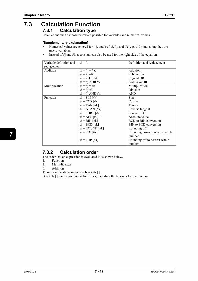
Chapter 7 Macro TC-32B
2004/01/22 7 - 12 eTCOMNCPR7-1.doc
7
7.3 Calculation Function7.3.1 Calculation typeCalculations such as those below are possible for variables and numerical values.
[Supplementary explanation]• Numerical values are entered for i, j, and k of #i, #j, and #k (e.g. #10), indicating they are
macro variables.• Instead of #j and #k, a constant can also be used for the right side of the equation.
Variable definition andreplacement
#i = #j Definition and replacement
Addition #i = #j + #K#i = #j -#k#i = #j OR #k#i = #j XOR #k
AdditionSubtractionLogical ORExclusive OR
Multiplication #i = #j * #k#i = #j /#k#i = #j AND #k
MultiplicationDivisionAND
Function #i = SIN [#k]#i = COS [#k]#i = TAN [#k]#i = ATAN [#k]#i = SQRT [#k]#i = ABS [#k]#i = BIN [#k]#i = BCD [#k]#i = ROUND [#k]#i = FIX [#k]
#i = FUP [#k]
SineCosineTangentReverse tangentSquare rootAbsolute valueBCD to BIN conversionBIN to BCD conversionRounding offRounding down to nearest wholenumberRounding off to nearest wholenumber
7.3.2 Calculation orderThe order that an expression is evaluated is as shown below.1. Function2. Multiplication3. AdditionTo replace the above order, use brackets [ ].Brackets [ ] can be used up to five times, including the brackets for the function.

TC-32B Chapter 7 Macro
2004/01/22 7 - 13 eTCOMNCPR7-1.doc
7
7.3.3 Precautions for calculation(Note 1) Formula
The right side of the equation can be connected using a constant,variable, function, or operator. When using a constant, any valuewithout a decimal point is regarded as having a decimal point at its end.[Example] #1 =12;, #1 is regarded as 12.000.
(Note 2) Angle calculationThe unit for SIN, COS, TAN, and ATAN functions is “degree”.For example, 90 degrees and 30 minutes is designated as 90.5 degrees.
(Note 3) Logical calculationLogical sum (OR), logical product (AND), and exclusive-or (XOR)perform the following calculation for each bit of the integral number.Decimal places are regarded as “as”.
(Note 4)Calculation
object Result for AND Result of OR Result of XOR
0 and 0 0 0 0
0 and 1 0 1 1
1 and 0 0 1 1
1 and 1 1 1 0
Conversion between BCD and BINBIN indicates binary number.BCD indicates binary-coded decimal number.The value of each digit in a decimal number is expressed as a 4-bitbinary number.[Example] 12 = 0001 (4 bits) 0010 (4 bits)The binary number 00010010 is the decimal number 18.When 12 is converted from BIN to BCD, the result will be 18.Conversion from BCD to BIN is performed in the reverse of the above.Decimal places in the conversion source number are always regardedas zero (0).
(Note 5) Range of constantThe range of constants that can be used in the formula is as below.-999999999 ~ -0.000000010+0.00000001 ~ +999999999The maximum number of digits that can be designated is 9 for a decimalnumber.
(Note 6) Calculation accuracyWhen calculation is performed for the macro statement, smallcalculation errors occur and these accumulate as the calculation isrepeated. However, the data is retained internally using up toapproximately 15 significant digits in floating-point format, thusensuring calculation accuracy.
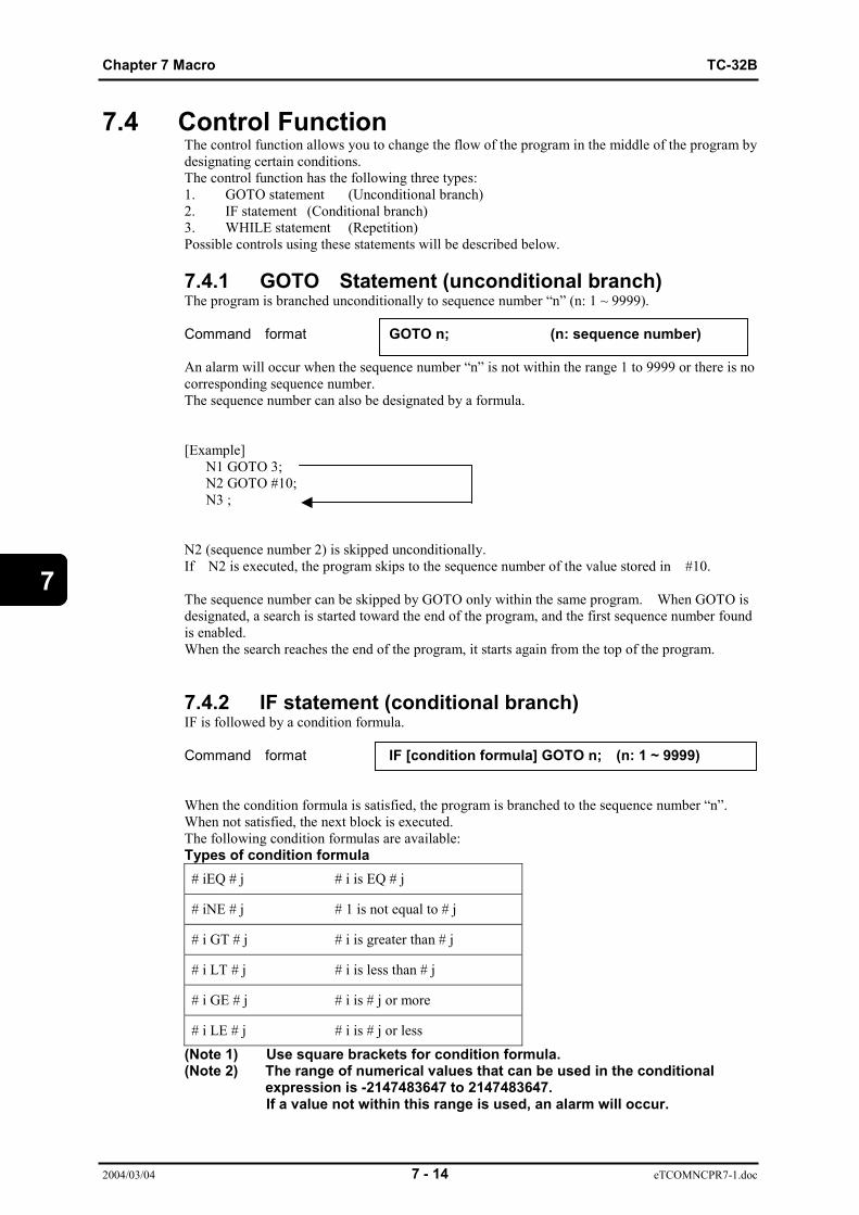
Chapter 7 Macro TC-32B
2004/03/04 7 - 14 eTCOMNCPR7-1.doc
7
7.4 Control FunctionThe control function allows you to change the flow of the program in the middle of the program bydesignating certain conditions.The control function has the following three types:1. GOTO statement (Unconditional branch)2. IF statement (Conditional branch)3. WHILE statement (Repetition)Possible controls using these statements will be described below.
7.4.1 GOTO Statement (unconditional branch)The program is branched unconditionally to sequence number “n” (n: 1 ~ 9999).
Command format GOTO n; (n: sequence number)
An alarm will occur when the sequence number “n” is not within the range 1 to 9999 or there is nocorresponding sequence number.The sequence number can also be designated by a formula.
[Example] N1 GOTO 3; N2 GOTO #10; N3 ;
N2 (sequence number 2) is skipped unconditionally.If N2 is executed, the program skips to the sequence number of the value stored in #10.
The sequence number can be skipped by GOTO only within the same program. When GOTO isdesignated, a search is started toward the end of the program, and the first sequence number foundis enabled.When the search reaches the end of the program, it starts again from the top of the program.
7.4.2 IF statement (conditional branch)IF is followed by a condition formula.
Command format IF [condition formula] GOTO n; (n: 1 ~ 9999)
When the condition formula is satisfied, the program is branched to the sequence number “n”.When not satisfied, the next block is executed.The following condition formulas are available:Types of condition formula# iEQ # j # i is EQ # j
# iNE # j # 1 is not equal to # j
# i GT # j # i is greater than # j
# i LT # j # i is less than # j
# i GE # j # i is # j or more
# i LE # j # i is # j or less
(Note 1) Use square brackets for condition formula.(Note 2) The range of numerical values that can be used in the conditional
expression is -2147483647 to 2147483647.If a value not within this range is used, an alarm will occur.

TC-32B Chapter 7 Macro
2004/01/22 7 - 15 eTCOMNCPR7-1.doc
7
[Example]
: :(1) IF[#100 EQ 50] GOTO 123; : :(2) IF[#101 GT 102] GOTO 123;
: :(3) GOTO 124; : :(4) N123; : :(5) N124; : :
At (1) above, If variable #100 is 50, the program skips to (4), where the sequence number is
123. If it is not 50, the program proceeds to the next block (2).At (2) above If #101 is larger than 102 (#101 > 102), the program skips to (4), where the
sequence number is 123. If #101 is less than 102 (#101 」 102), the program proceeds to the next block
(3).At (3) above, the program unconditionally skips to (5) via the GOTO statement.
7.4.3 WHILE statement (repetition)Command format WHILE [condition formula] DOm ~ ENDm; (m = 1 ~ 4)
WHILE is followed by a condition formula.When the condition formula is satisfied, the program between DO and END is executed.When not satisfied, the program proceeds to the block after END.When WHILE (condition formula) is omitted, the program between DOm and END is repeatedendlessly.Use square brackets for the condition formula.[Example 1] WHILE statement]WHILE [condition formula] DO m; (m = 1 ~ 4)
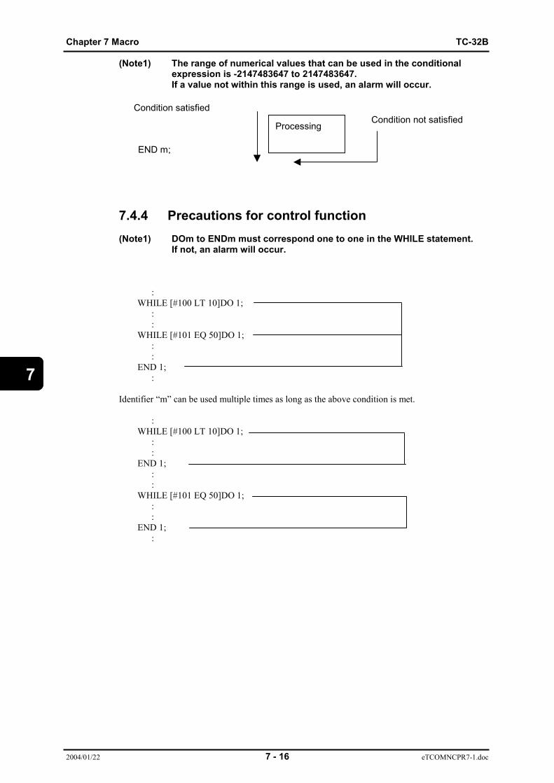
Chapter 7 Macro TC-32B
2004/01/22 7 - 16 eTCOMNCPR7-1.doc
7
(Note1) The range of numerical values that can be used in the conditionalexpression is -2147483647 to 2147483647.If a value not within this range is used, an alarm will occur.
7.4.4 Precautions for control function(Note1) DOm to ENDm must correspond one to one in the WHILE statement.
If not, an alarm will occur.
: WHILE [#100 LT 10]DO 1; : : WHILE [#101 EQ 50]DO 1; : : END 1; :
Identifier “m” can be used multiple times as long as the above condition is met.
: WHILE [#100 LT 10]DO 1; : : END 1; : : WHILE [#101 EQ 50]DO 1; : : END 1; :
Processing
Condition satisfied
END m;
Condition not satisfied
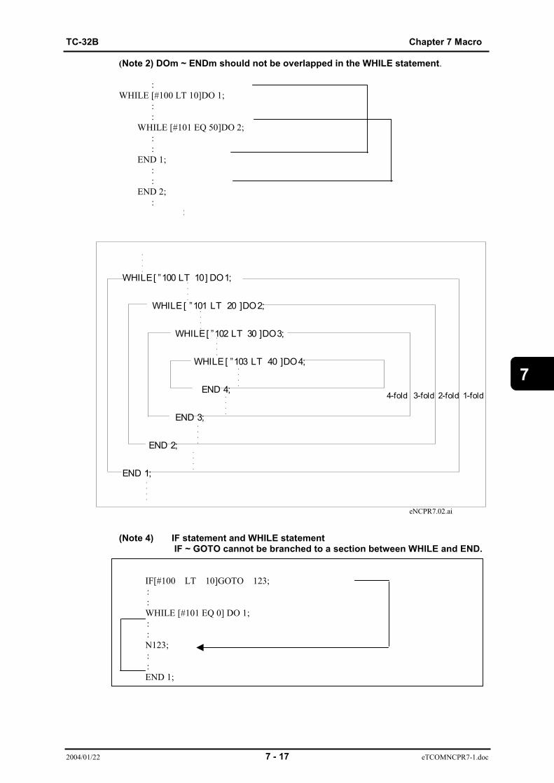
TC-32B Chapter 7 Macro
2004/01/22 7 - 17 eTCOMNCPR7-1.doc
7
WHILE [ ”100 LT 10 ] DO 1;
WHILE [ ”101 LT 20 ]DO 2;
WHILE [ ”102 LT 30 ]DO 3;
WHILE [ ”103 LT 40 ]DO 4;
END 4;
END 3;
END 2;
END 1;
.
.
.
.
.
.
.
.
.
.
.
.
.
.
.
.
.
.
.
.
.
.
.
.
.
.
.
.
4-fold 3-fold 2-fold 1-fold
.
.
.
.
.
.
.
.
:
(Note 2) DOm ~ ENDm should not be overlapped in the WHILE statement.
:WHILE [#100 LT 10]DO 1; : : WHILE [#101 EQ 50]DO 2; : : END 1; : : END 2; :
eNCPR7.02.ai
(Note 4) IF statement and WHILE statement IF ~ GOTO cannot be branched to a section between WHILE and END.
IF[#100 LT 10]GOTO 123; : :
WHILE [#101 EQ 0] DO 1; : :
N123; : :
END 1;
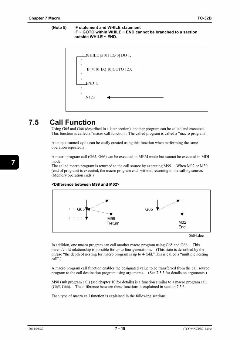
Chapter 7 Macro TC-32B
2004/01/22 7 - 18 eTCOMNCPR7-1.doc
7
(Note 5) IF statement and WHILE statementIF ~ GOTO within WHILE ~ END cannot be branched to a sectionoutside WHILE ~ END.
WHILE [#101 EQ 0] DO 1; : : IF[#101 EQ 10]GOTO 123; : :
END 1; : :
N123
7.5 Call FunctionUsing G65 and G66 (described in a later section), another program can be called and executed.This function is called a “macro call function”. The called program is called a “macro program”.
A unique canned cycle can be easily created using this function when performing the sameoperation repeatedly.
A macro program call (G65, G66) can be executed in MEM mode but cannot be executed in MDImode.The called macro program is returned to the call source by executing M99. When M02 or M30(end of program) is executed, the macro program ends without returning to the calling source.(Memory operation ends.)
<Difference between M99 and M02>
0604.doc
In addition, one macro program can call another macro program using G65 and G66. Thisparent/child relationship is possible for up to four generations. (This state is described by thephrase “the depth of nesting for macro program is up to 4-fold.”This is called a “multiple nestingcall”.)
A macro program call function enables the designated value to be transferred from the call sourceprogram to the call destination program using arguments. (See 7.5.3 for details on arguments.)
M98 (sub program call) (see chapter 10 for details) is a function similar to a macro program call(G65, G66). The difference between these functions is explained in section 7.5.3.
Each type of macro call function is explained in the following sections.
G65 G65 M99 Return M02
End
TC-32B Chapter 7 Macro
2004/01/22 7 - 19 eTCOMNCPR7-1.doc
7
7.5.1 Simple call functionG65 is generally used to call a macro program.
Command format G65 P_L_(Argument);
P : Macro program number to be calledL : Number of calls to be repeated (up to 9999)
If “L” is omitted, “1”is automatically selected.
(Argument): Data transferred to macro. Can be omitted.See 7.5.3 for argument.
[Example 1] G65 P200;This format specifies that a program between Nos. 200 and 299 is called once.
[Example 2] G65 P200L2;and G65 P200; G65 P200;This format specifies that a program between Nos. 200 and 299 is called twice.

Chapter 7 Macro TC-32B
2004/01/22 7 - 20 eTCOMNCPR7-1.doc
7
7.5.2 Modal call functionWhen a macro program is automatically called each time an axis movement command is givenonce registered, it is called a “modal call function”.
Use G66 to register a modal call and G67 to cancel registration. When a modal call is registered,the macro program is executed after each axis movement.
Command format G66 P_L_(Argument);
P : Macro program number to be calledL : Number of calls to be repeated (up to 9999)
If “L” is omitted, “1” is automatically selected. (See descriptions for G65).(Argument) :Data transferred to macro. Can be omitted.
See 7.5.3 for argument.
To cancel a modal call, use the following command.
Command format G67;
[Example 1]G66 P10: (1) Register call for program number 10.G01X10.0Y10.0; (2) Call program number 10 after execution of.G01X1.0Y1.0; (3) Call program number 10 after execution of .G67; (4) Cancel registration.G01X10.0Y10.0; (5) Does not call any program.G01X1.0Y1.0; (6) Does not call any program.Program number 10 is called once after (2) is executed. Program number 10 is also called onceafter (3) is executed.Programs are not called after (5) and (6) are executed.
(Note 1) G67 must be designated by a program besides a call program.G66 mode can also be canceled using M30.
(Note 2) G66 cannot be designated in G66 mode.
(Note 3) G66 command is only used to register macro program call.Macro programs cannot be called with this command.
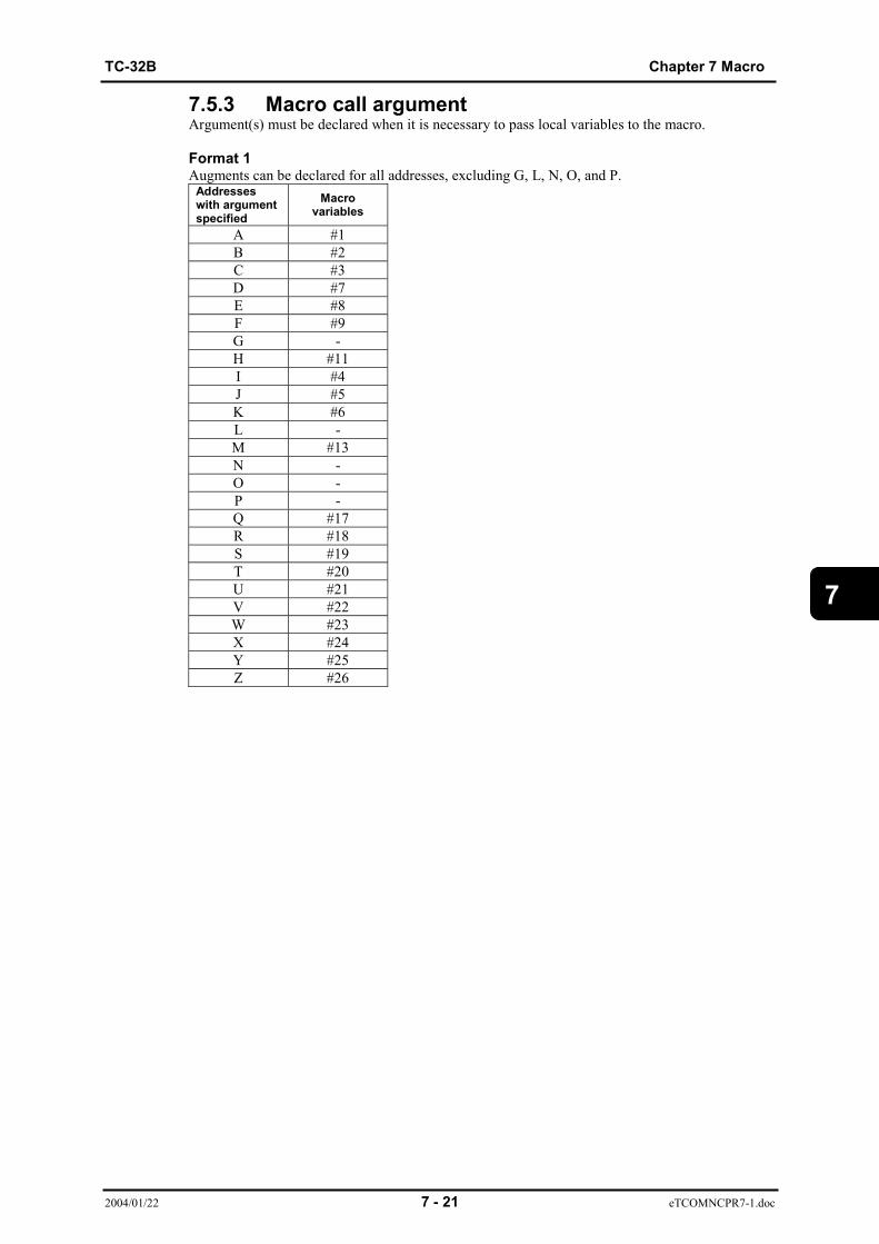
TC-32B Chapter 7 Macro
2004/01/22 7 - 21 eTCOMNCPR7-1.doc
7
7.5.3 Macro call argumentArgument(s) must be declared when it is necessary to pass local variables to the macro.
Format 1Augments can be declared for all addresses, excluding G, L, N, O, and P.
Addresseswith argumentspecified
Macrovariables
A #1B #2C #3D #7E #8F #9G -H #11I #4J #5K #6L -M #13N -O -P -Q #17R #18S #19T #20U #21V #22W #23X #24Y #25Z #26
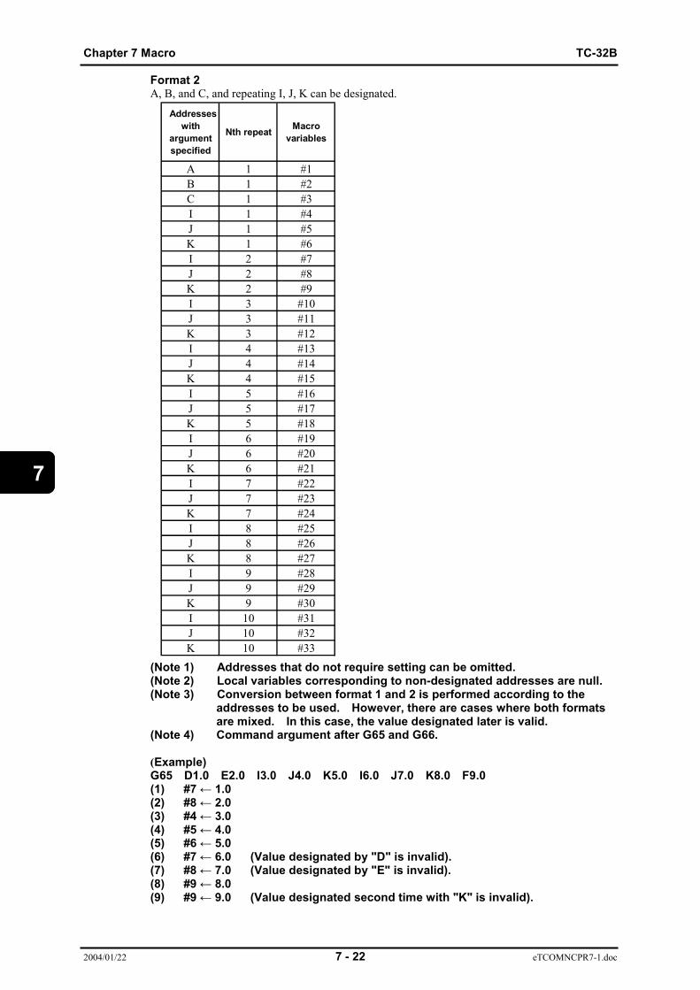
Chapter 7 Macro TC-32B
2004/01/22 7 - 22 eTCOMNCPR7-1.doc
7
Format 2A, B, and C, and repeating I, J, K can be designated.
(Note 1) Addresses that do not require setting can be omitted.(Note 2) Local variables corresponding to non-designated addresses are null.(Note 3) Conversion between format 1 and 2 is performed according to the
addresses to be used. However, there are cases where both formatsare mixed. In this case, the value designated later is valid.
(Note 4) Command argument after G65 and G66.
(Example)G65 D1.0 E2.0 I3.0 J4.0 K5.0 I6.0 J7.0 K8.0 F9.0(1) #7 ← 1.0(2) #8 ← 2.0(3) #4 ← 3.0(4) #5 ← 4.0(5) #6 ← 5.0(6) #7 ← 6.0 (Value designated by "D" is invalid).(7) #8 ← 7.0 (Value designated by "E" is invalid).(8) #9 ← 8.0(9) #9 ← 9.0 (Value designated second time with "K" is invalid).
Addresseswith
argumentspecified
Nth repeat Macrovariables
A 1 #1B 1 #2C 1 #3I 1 #4J 1 #5K 1 #6I 2 #7J 2 #8K 2 #9I 3 #10J 3 #11K 3 #12I 4 #13J 4 #14K 4 #15I 5 #16J 5 #17K 5 #18I 6 #19J 6 #20K 6 #21I 7 #22J 7 #23K 7 #24I 8 #25J 8 #26K 8 #27I 9 #28J 9 #29K 9 #30I 10 #31J 10 #32K 10 #33
TC-32B Chapter 7 Macro
2004/01/22 7 - 23 eTCOMNCPR7-1.doc
7
7.5.4 Difference between G65 and M981. Arguments can be designated for G65, but cannot be designated for M98.2. Local variables are available for G65 depending on the depth of nesting, but are not
available for M98.3. Calling depth of nesting for G65 is up to 4-fold.
When combined with that for M98, up to 8-fold are possible.

Chapter 7 Macro TC-32B
2004/01/22 7 - 24 eTCOMNCPR7-1.doc
7
M30; M99; 99; M99; M99;
7.5.5 Multiple nesting callMacro calling depth of nesting is up to 4 -fold.Local variables (#1 ~ #26)are provided for each macro level. When macro is called by G65, localvariable of called macro level is stored once, and new local variable of called macro program isprepared. When M99 is executed, stored local variable becomes valid.Common variables can be read and written even between different macro levels.
Level 0 Level 1 Level 2 Level 3 Level 4
Common variables : Commonly read and written from any macro level.
#100 ~ #199#500 ~ #599
Main program
G65P8010I3.J4.;
Program 8010
G65P8020I5.J6.;
Program 8020
G65P8030I7.J8.;
G65P8040I9.J10.;
Program 8030 Program 8040
#1 . .#4#5 . .#9#11#13#17 . .#26
#1 . .#4 3.0#5 4.0 . .#9#11#13#17 . .#26
#1 . .#4 5.0#5 6.0 . .#9#11#13#17 . .#26
#1 . .#4 7.0#5 8.0 . .#9#11#13#17 . .#26
#1 . .#4 9.0#5 10.0 . .#9#11#13#17 . .#26
Local variable of level 0
Local variable oflevel 1
Local variable oflevel 2
Local variable oflevel 3
Local variable oflevel 4
TC-32B Chapter 8 Automatic work measurement
2004/01/30 8 - 1 eTCOMNCPR8-1.doc
8
CHAPTER 8
AUTOMATIC WORK MEASUREMENT
8.1 Before automatic work measurement8.2 Setting of data on automatic work measurement8.3 Operation of automatic work measurement8.4 Display of the measured results8.5 Lock key operations
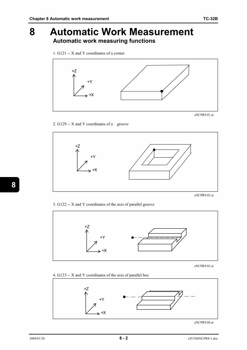
Chapter 8 Automatic work measurement TC-32B
2004/01/30 8 - 2 eTCOMNCPR8-1.doc
8
8 Automatic Work MeasurementAutomatic work measuring functions
1. G121 -- X and Y coordinates of a corner
eNCPR9.01.ai
2. G129 -- X and Y coordinates of a groove
eNCPR9.02.ai
3. G122 -- X and Y coordinates of the axis of parallel groove
eNCPR9.03.ai
4. G123 -- X and Y coordinates of the axis of parallel bos
eNCPR9.04.ai
+Y
+X
+Z
+Y
+X
+Z
+Y
+X
+Z
+Y
+X
+Z

TC-32B Chapter 8 Automatic work measurement
2004/01/30 8 - 3 eTCOMNCPR8-1.doc
8
5. G124,G126 -- X and Y coordinates of the center of a hole
eNCPR9.05.ai
6. G125,G127 -- X and Y coordinates of the center of a boss
7. G128 -- Z coordinate of the top surface of a workpiece
+Y
+X
+Z
+Y
+X
+Z
+Y
+X
+Z
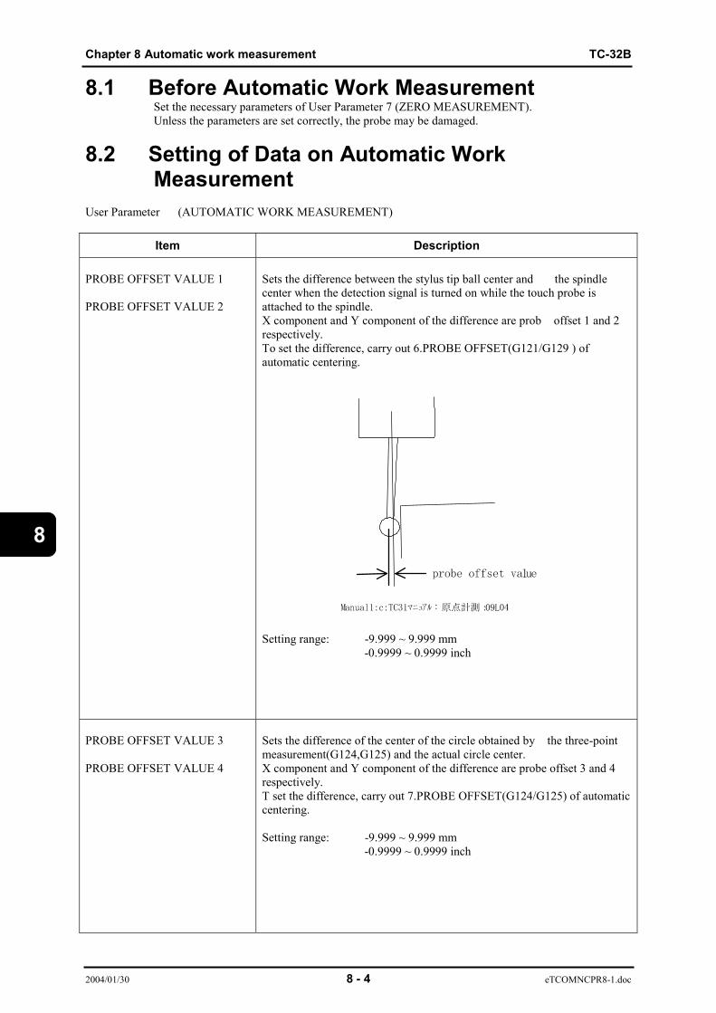
Chapter 8 Automatic work measurement TC-32B
2004/01/30 8 - 4 eTCOMNCPR8-1.doc
8
8.1 Before Automatic Work MeasurementSet the necessary parameters of User Parameter 7 (ZERO MEASUREMENT).Unless the parameters are set correctly, the probe may be damaged.
8.2 Setting of Data on Automatic WorkMeasurement
User Parameter (AUTOMATIC WORK MEASUREMENT)
Item Description
PROBE OFFSET VALUE 1
PROBE OFFSET VALUE 2
Sets the difference between the stylus tip ball center and �the spindlecenter when the detection signal is turned on while the touch probe isattached to the spindle.X component and Y component of the difference are prob �offset 1 and 2respectively.To set the difference, carry out 6.PROBE OFFSET(G121/G129 ) ofautomatic centering.
Setting range: -9.999 ~ 9.999 mm-0.9999 ~ 0.9999 inch
PROBE OFFSET VALUE 3
PROBE OFFSET VALUE 4
Sets the difference of the center of the circle obtained by �the three-pointmeasurement(G124,G125) and the actual circle center.X component and Y component of the difference are probe offset 3 and 4respectively.T set the difference, carry out 7.PROBE OFFSET(G124/G125) of automaticcentering.
Setting range: -9.999 ~ 9.999 mm-0.9999 ~ 0.9999 inch

TC-32B Chapter 8 Automatic work measurement
2004/01/30 8 - 5 eTCOMNCPR8-1.doc
8
Item Description
MEASURING MOTION
(0:TYPE1 1:TYPE2)
(0:TYPE1)1) It is checked that the detection signal is off.2) The probe moves in the specified axis direction at the speed preset to MEASURING SPEED 1.3) When the detection signal has turned on, the axis stops traveling.4) The probe moves forward for the RETURN DISTANCE AFT MEASURNG.5) The probe moves in the specified axis direction at the speed preset to MEASURING SPEED 2.6) When the detection signal has turned on, the axis stopstraveling.7) The probe returns to the position of 4).8) It is checked that the detection signal is off.
eNCPR9.09.ai(1:TYPE2)1) It is checked that the detection signal is off.2) The probe moves in the specified axis direction at the speed preset to MEASURERING SPEED 2.3) When the detection signal has turned on, the axis raveling.4) The probe moves forward for the RETURN DISTANCE AFT MEASURNG.5) It is checked that the detection signal is off.
eNCPR9.10.ai
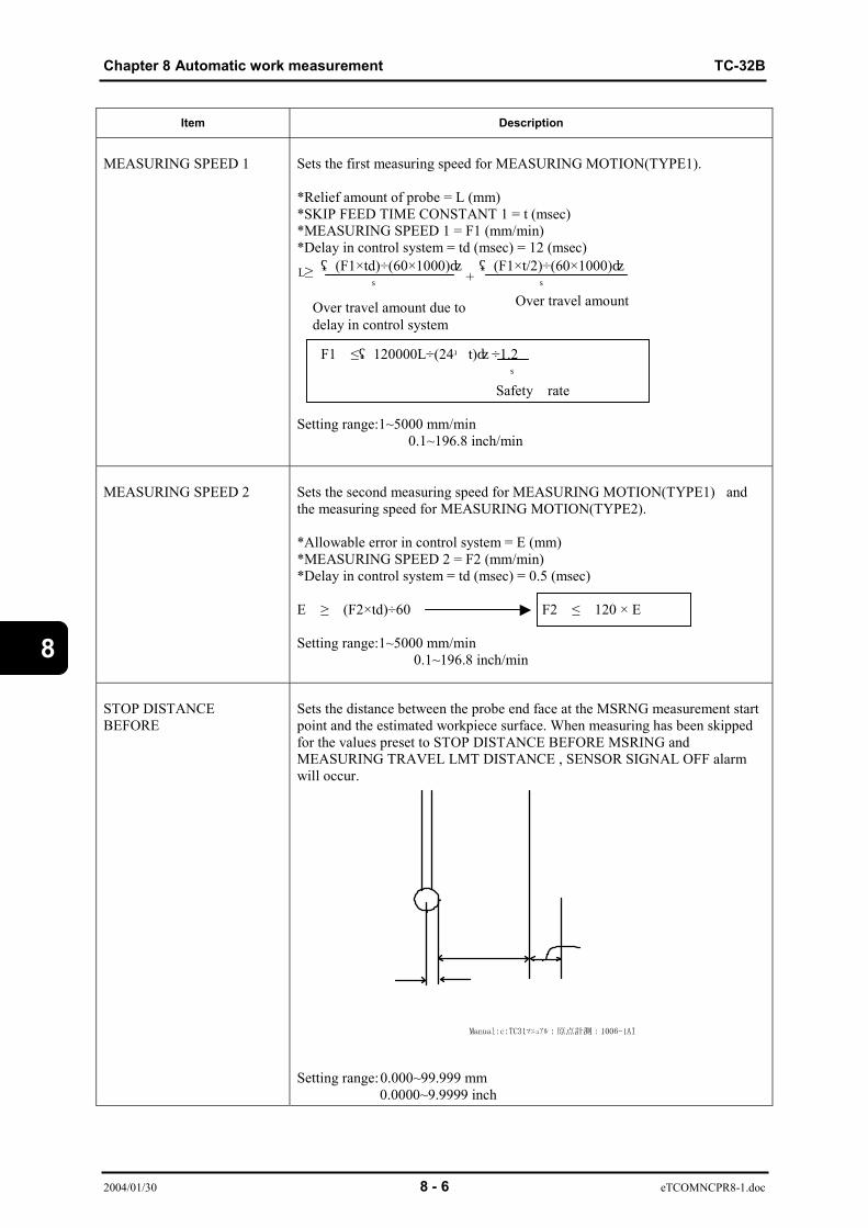
Chapter 8 Automatic work measurement TC-32B
2004/01/30 8 - 6 eTCOMNCPR8-1.doc
8
Item Description
MEASURING SPEED 1 Sets the first measuring speed for MEASURING MOTION(TYPE1).
*Relief amount of probe = L (mm)*SKIP FEED TIME CONSTANT 1 = t (msec)*MEASURING SPEED 1 = F1 (mm/min)*Delay in control system = td (msec) = 12 (msec)((F1×td)÷(60×1000)) ((F1×t/2)÷(60×1000)) ↑ ↑
F1 ≤(120000L÷(24+t))÷1.2 ↑ Safety rate
Setting range:1~5000 mm/min 0.1~196.8 inch/min
MEASURING SPEED 2 Sets the second measuring speed for MEASURING MOTION(TYPE1)�andthe measuring speed for MEASURING MOTION(TYPE2).
*Allowable error in control system = E (mm)*MEASURING SPEED 2 = F2 (mm/min)*Delay in control system = td (msec) = 0.5 (msec)
E ≥ (F2×td)÷60 F2 ≤ 120 × E
Setting range:1~5000 mm/min 0.1~196.8 inch/min
STOP DISTANCEBEFORE
Sets the distance between the probe end face at the MSRNG measurement startpoint and the estimated workpiece surface. When measuring has been skippedfor the values preset to STOP DISTANCE BEFORE MSRING andMEASURING TRAVEL LMT DISTANCE , SENSOR SIGNAL OFF alarmwill occur.
Setting range:0.000~99.999 mm 0.0000~9.9999 inch
L≥
Over travel amount due todelay in control system
Over travel amount+
TC-32B Chapter 8 Automatic work measurement
2004/01/30 8 - 7 eTCOMNCPR8-1.doc
8
Item Description
MEASURING TRAVEL LMTDISTANCE
Sets the amount of overtravel when the measuring skip has exceededthe estimated value(program command value).Setting range:0.000~99.999 mm
0.0000~9.9999 inch
MEASUREMENT TOLERANCE 1 When the difference between the measured value and the estimatedvalue (program command value) has exceeded the �preset value,MEASD VAL ERR LRG(1) will occur. When 0 is set,the value errorcheck is not carried out.Setting range:0.000~99.999 mm 0.0000~9.9999 inch
MEASUREMENT TOLERANCE 2 If the difference between the current measurement result and theprevious measurement result exceeds the setting range, MEASDVAL ERR LRG(2) occurs. However, the difference is notchecked in the following cases:*Zero (0) is set.*1st automatic work measurement is performed after the power isturned on (1st measurement for each of measurement results 1 to 4).*No previous measurement result exists.*Current G code differs from the previous G code.Setting range:0.000~99.999 mm
0.0000~9.9999 inch
MEASURNGRETURN DISTANCE AFT
Sets the amount that the measuring probe retracts where it hascontacted the non measuring object during automatic measurement.
*RETURN DISTANCE AFT MEASURNG = Lb (mm)*SKIP FEED TIME CONSTANT 1 = t (msec)*MEASURING SPEED 2 = F2 (mm/min)
Lb ≥ MAX (1.0,F2×t/6000)
Setting range:0.000~99.999 mm 0.0000~9.9999 inch

Chapter 8 Automatic work measurement TC-32B
2004/01/30 8 - 8 eTCOMNCPR8-1.doc
8
(Note)- The setting values of MEASURING SPEED, RETURN DISTANCE AFT MEASURNG and so
on differ according to the probe mounted. Consult the probe maker and set the values.
- During automatic work measurement, the speed that the probe moves to themeasurement start point or returns from the measured point conforms to the modal ofG00 and G01.G00...Rapid traverse rateG01...F command valueG02/G03/G102/G103/G202/G203... IN ARC MODE alarm will occur
- Perform automatic work measurement with the tool offset function ON or the probe maybe damaged.
- Check that the chips are not stuck to the measuring probe tip and the surface of theworkpiece to be measured. We shall not bear responsibility for the decreased measurement accuracy due to the above cause.
- The mode cannot be changed during automatic work measurement.If mode selection is attempted, DURING AUTOMATIC WORK MEASURMENT alarm willoccur.
- To prevent the probe from being damaged, press the [SINGL] key for the first automaticwork measurement and check the condition every single operation.
- Tool length offset set first for automatic work measurement.
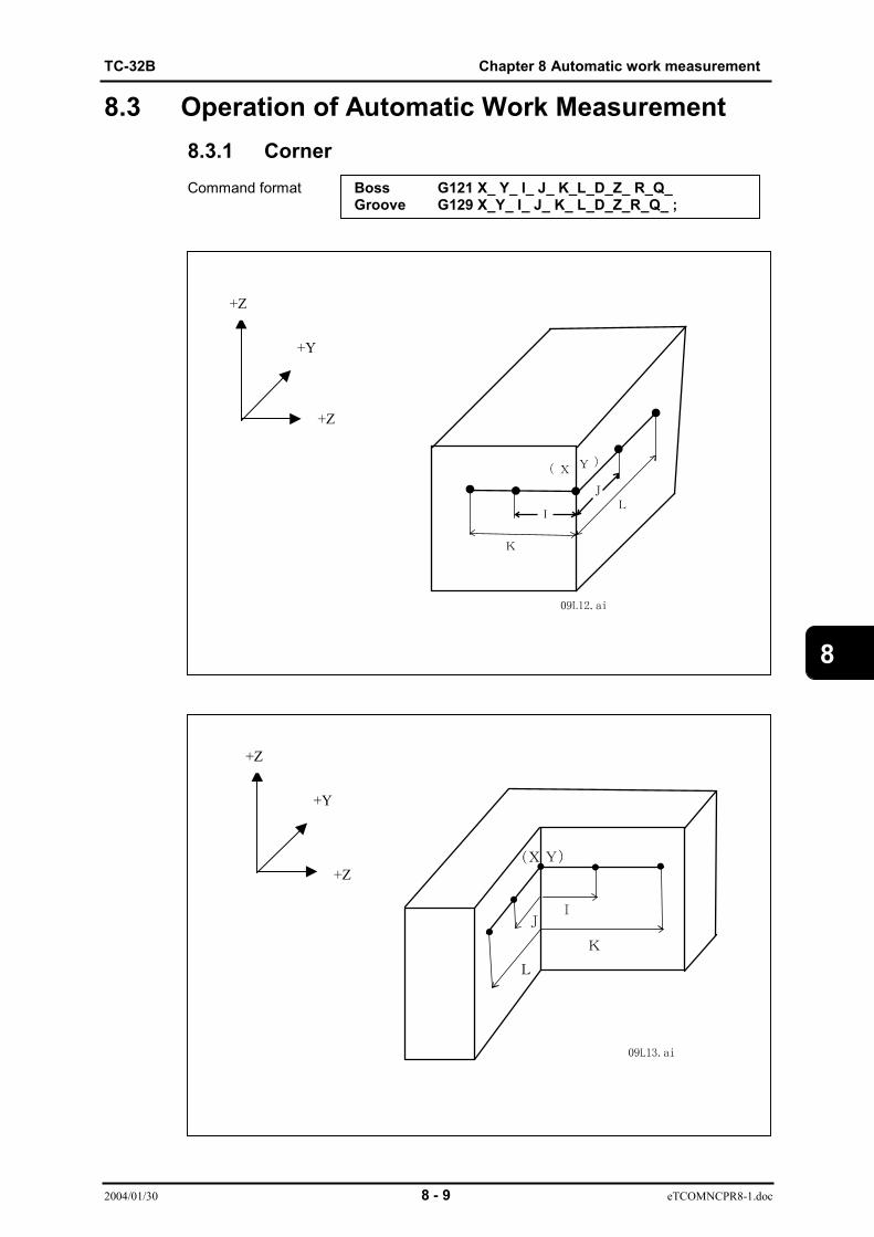
TC-32B Chapter 8 Automatic work measurement
2004/01/30 8 - 9 eTCOMNCPR8-1.doc
8
8.3 Operation of Automatic Work Measurement8.3.1 CornerCommand format Boss G121 X_ Y_ I_ J_ K_L_D_Z_ R_Q_
Groove G129 X_Y_ I_ J_ K_ L_D_Z_R_Q_ ;
+Y
+Z
+Z
+Y
+Z
+Z

Chapter 8 Automatic work measurement TC-32B
2004/01/30 8 - 10 eTCOMNCPR8-1.doc
8
X,Y ...Estimated corner valueI ,K ...X-axis position when measuring in the Y direction, offset value from (X, Y)J ,L ...Y-axis position when measuring in the Y direction, offset value from (X, Y)D ...Tool offset numberZ ...Z coordinate during measurementR ...Z coordinate of return point when the Z axis has traveled from one measurement point to
the other measurement point or when the movement has com pleted.Q ...Register No. that stores the measured results ("1" when omitted)
(Note 1)When either “I”・or “J” is not commanded , when “I” is zero (o) , or when “J” is zero (0), an alarm occurs.
(Note 2)When "K" or "L" is commanded, the tilt angle (the angle used for coordinaterotation) is calculated should the work piece become tilted. An [ZERO MESRADRS ERR] error will occur when both "K" and "L" are commanded or zero (0) iscommanded.
(Note 3)Before executing G121/ G129, execute PROBE OFFSET VALUE (G121/G129) ofCENTER ALIGNMENT and set the offset value to PROBE OFFSET VALUE 1 andPROBE OFFSET VALUE 2 of parameter 7.
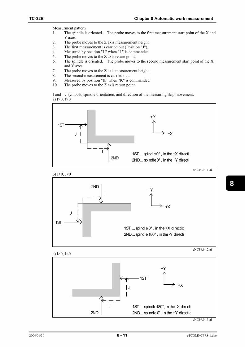
TC-32B Chapter 8 Automatic work measurement
2004/01/30 8 - 11 eTCOMNCPR8-1.doc
8
Measurment pattern1. The spindle is oriented. The probe moves to the first measurement start point of the X and
Y axes.2. The probe moves to the Z axis measurement height.3. The first measurement is carried out (Position "J").4. Measured by position "L" when "L" is commanded5. The probe moves to the Z axis return point.6. The spindle is oriented. The probe moves to the second measurement start point of the X
and Y axes.7. The probe moves to the Z axis measurement height.8. The second measurement is carried out.9. Measured by position "K" when "K" is commanded10. The probe moves to the Z axis return point.
I and J symbols, spindle orientation, and direction of the measuring skip movement.a) I>0, J>0
eNCPR9.11.aib) I>0, J<0
eNCPR9.12.aic) I>0, J<0
eNCPR9.13.ai
J
I
+Y
+X
1ST
2ND1ST ... spindle 0° , in the +X directi2ND... spindle0° , in the +Y directi
I
J
1ST
2ND
1ST ...spindle 0° , in the +X directio2ND ...spindle 180° , in the -Y directi
+Y
+X
+Y
+X
I
J
2ND
1ST
1ST ... spindle180°, in the -X directi2ND... spindle 0°, in the +Y directio

Chapter 8 Automatic work measurement TC-32B
2004/01/30 8 - 12 eTCOMNCPR8-1.doc
8
d) I<0, J<0
eNCPR9.14.ai
Measurement pattern1. The spindle is oriented. The probe moves to the first measurement start point of the X and
Y axes.2. The probe moves to the Z axis measurement height.3. The first measurement is carried out (Position "J").4. Measured by position "L" when "L" is commanded5. The spindle is oriented. The probe moves to the second measurement start point of the X
and Y axes.6. The second measurement is carried out.7. Measured by position "K" when "K" is commanded8. The probe moves to the Z axis return point.
a) I<0, J<0
eNCPR9.15.aib) I<0, J>0
eNCPR9.16.ai
IJ
1ST
2ND
1ST... spindle180°, in the -X directi2ND... spindle180°, in the-Y directio
+Y
+X
1ST
2ND
1ST ... spindle 180° , in the -X directi2ND... spindle 180° , in the -Y directi
+Y
+X
+Y
+X
1ST
2ND
1ST ... spindle 180° , in the -X directi2ND... spindle 0° , in the +Y direction

TC-32B Chapter 8 Automatic work measurement
2004/01/30 8 - 13 eTCOMNCPR8-1.doc
8
c) I<0, J<0
eNCPR9.17.aid) I>0 , J>0
eNCPR9.18.ai
8.3.2 Parallelgroove G122 X_ Y_ I_(J_) D_ Z_ R_ Q_boss G123 X_ Y_ I_(J_) D_ Z_ R_ Q_
eNCPR9.19.ai
eNCPR9.20.aiX,Y ... Estimated groove (boss) center valueI,J ... Width of groove
I : Measures in the X direction. J : Measures in the Y direction.
Note: I and J cannot be commanded at the same time.
JI
1ST2ND
1ST ... spindle 0° , in the +X direction2ND... spindle 180° , in the -Y directi
+Y
+X
IJ
1ST ... spindle 0° , in the +X directi2ND... spindle 0° , in the +Y directi1ST
2ND
+Y
+X
Command format
+X
+Y
+Z
+Y
+
+Z
X
+Y
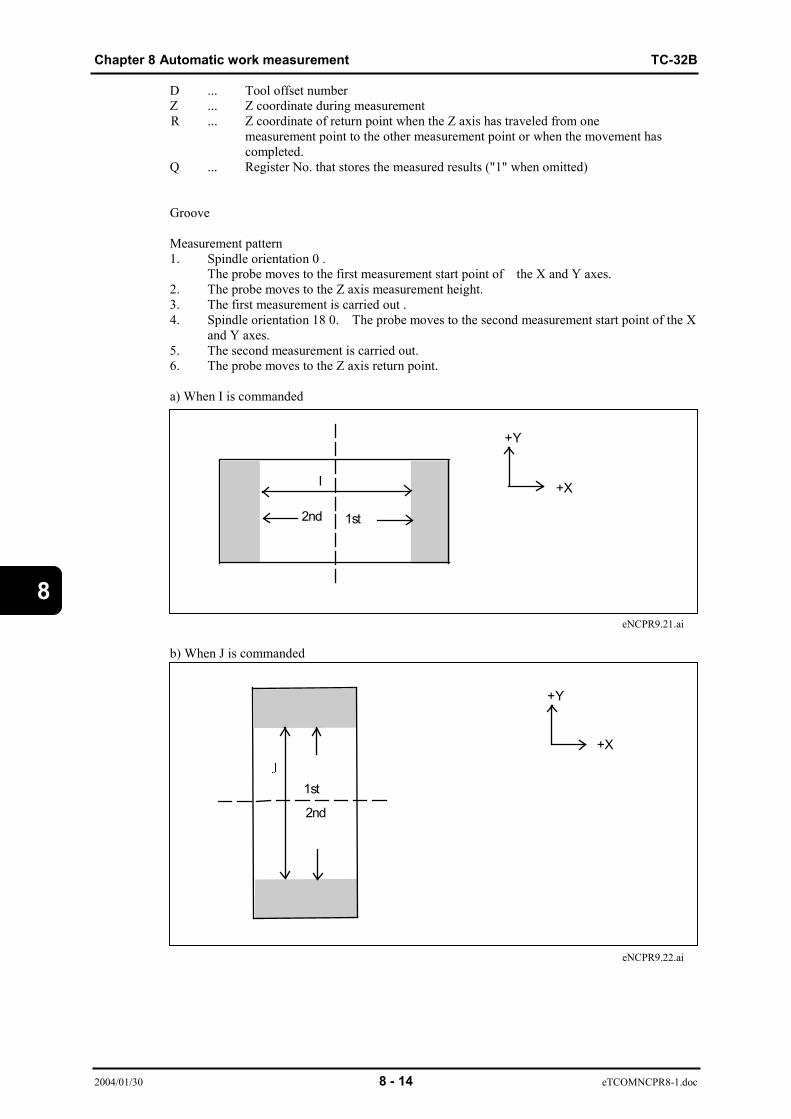
Chapter 8 Automatic work measurement TC-32B
2004/01/30 8 - 14 eTCOMNCPR8-1.doc
8
D ... Tool offset numberZ ... Z coordinate during measurementR ... Z coordinate of return point when the Z axis has traveled from one
measurement point to the other measurement point or when the movement hascompleted.
Q ... Register No. that stores the measured results ("1" when omitted)
Groove
Measurement pattern1. Spindle orientation 0 .
The probe moves to the first measurement start point of the X and Y axes.2. The probe moves to the Z axis measurement height.3. The first measurement is carried out .4. Spindle orientation 18 0. The probe moves to the second measurement start point of the X
and Y axes.5. The second measurement is carried out.6. The probe moves to the Z axis return point.
a) When I is commanded
eNCPR9.21.ai
b) When J is commanded
eNCPR9.22.ai
I
+Y
2nd 1st
2nd
1st
+Y
+X
+X
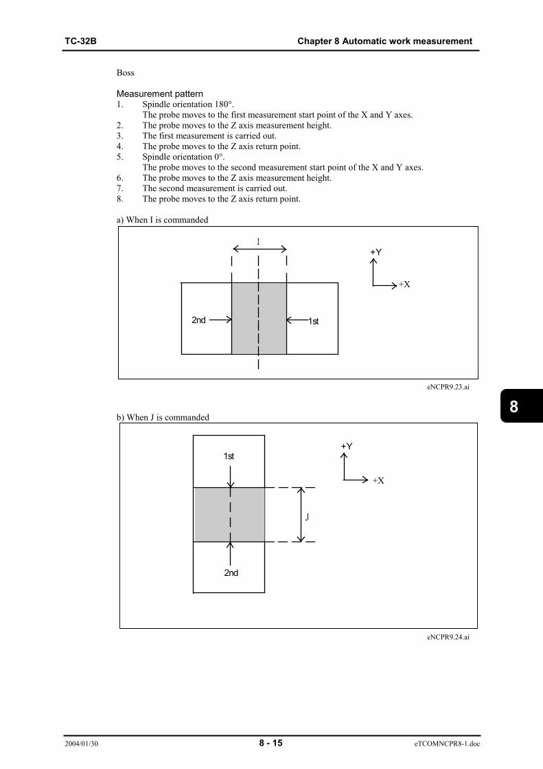
TC-32B Chapter 8 Automatic work measurement
2004/01/30 8 - 15 eTCOMNCPR8-1.doc
8
Boss
Measurement pattern1. Spindle orientation 180°.
The probe moves to the first measurement start point of the X and Y axes.2. The probe moves to the Z axis measurement height.3. The first measurement is carried out.4. The probe moves to the Z axis return point.5. Spindle orientation 0°.
The probe moves to the second measurement start point of the X and Y axes.6. The probe moves to the Z axis measurement height.7. The second measurement is carried out.8. The probe moves to the Z axis return point.
a) When I is commanded
eNCPR9.23.ai
b) When J is commanded
eNCPR9.24.ai
2nd 1st
+Y
+
1st
2nd
+Y
+X
+X

Chapter 8 Automatic work measurement TC-32B
2004/01/30 8 - 16 eTCOMNCPR8-1.doc
8
8.3.3 CircleThe circle center is calculated by measuring three points.
hole G124 X_ Y_ I_ D_Z_ R_Q_boss G125 X_ Y_ I_ D_ Z_ R_Q_
The circle center is calcutaled by measuring four points.
hole G126 X_ Y_ I_D_ Z_ R_Q_boss G127 X_ Y_ I_ D_Z_ R_Q_
X,Y … Estimated hole (boss) center valueI … Diameter of measuring circleD … Tool offset numberZ … Z coordinate during measurementR … Z coordinate of return point when the Z axis has traveled from one measurement point to the other measurement point or when the movement has completed.Q … Register No. that stores the measured results ("1" when omitted)
Command format
Command format
+X
+Y
+Z
+X
+Y
+Z
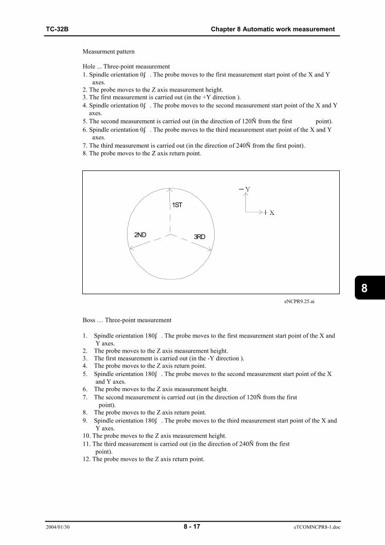
TC-32B Chapter 8 Automatic work measurement
2004/01/30 8 - 17 eTCOMNCPR8-1.doc
8
Measurment pattern
Hole ... Three-point measurement1. Spindle orientation 0゜. The probe moves to the first measurement start point of the X and Y axes.2. The probe moves to the Z axis measurement height.3. The first measurement is carried out (in the +Y direction ).4. Spindle orientation 0゜. The probe moves to the second measurement start point of the X and Y axes.5. The second measurement is carried out (in the direction of 120。 from the first point).6. Spindle orientation 0゜. The probe moves to the third measurement start point of the X and Y axes.7. The third measurement is carried out (in the direction of 240。 from the first point).8. The probe moves to the Z axis return point.
eNCPR9.25.ai
Boss … Three-point measurement 1. Spindle orientation 180゜. The probe moves to the first measurement start point of the X and Y axes.2. The probe moves to the Z axis measurement height.3. The first measurement is carried out (in the -Y direction ).4. The probe moves to the Z axis return point.5. Spindle orientation 180゜. The probe moves to the second measurement start point of the X and Y axes.6. The probe moves to the Z axis measurement height.7. The second measurement is carried out (in the direction of 120。 from the first point).8. The probe moves to the Z axis return point.9. Spindle orientation 180゜. The probe moves to the third measurement start point of the X and Y axes.10. The probe moves to the Z axis measurement height.11. The third measurement is carried out (in the direction of 240。 from the first point).12. The probe moves to the Z axis return point.
1ST
2ND 3RD
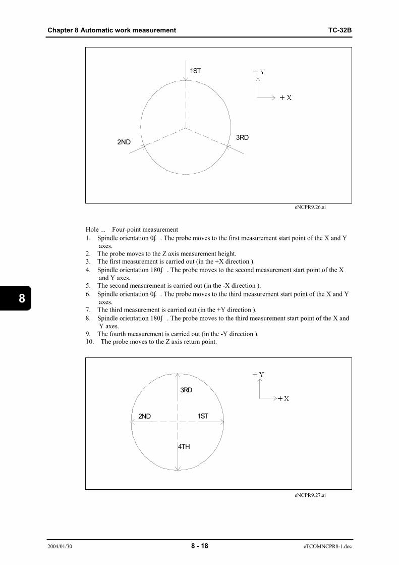
Chapter 8 Automatic work measurement TC-32B
2004/01/30 8 - 18 eTCOMNCPR8-1.doc
8
eNCPR9.26.ai
Hole ... Four-point measurement1. Spindle orientation 0゜. The probe moves to the first measurement start point of the X and Y axes.2. The probe moves to the Z axis measurement height.3. The first measurement is carried out (in the +X direction ).4. Spindle orientation 180゜. The probe moves to the second measurement start point of the X and Y axes.5. The second measurement is carried out (in the -X direction ).6. Spindle orientation 0゜. The probe moves to the third measurement start point of the X and Y axes.7. The third measurement is carried out (in the +Y direction ).8. Spindle orientation 180゜. The probe moves to the third measurement start point of the X and Y axes.9. The fourth measurement is carried out (in the -Y direction ).10. The probe moves to the Z axis return point.
eNCPR9.27.ai
1ST
2ND 3RD
2ND 1ST
3RD
4TH

TC-32B Chapter 8 Automatic work measurement
2004/01/30 8 - 19 eTCOMNCPR8-1.doc
8
Boss ... Four-point measurement1. Spindle orientation 180゜. The probe moves to the first measurement start point of the X and Y axes.2. The probe moves to the Z axis measurement height.3. The first measurement is carried out (in the -X direction ).4. The probe moves to the Z axis return point.5. Spindle orientation 0゜. The probe moves to the second measurement start point of the X and Y axes.6. The probe moves to the Z axis measurement height.7. The second measurement is carried out (in the +X direction ).8. The probe moves to the Z axis return point.9. Spindle orientation 180゜. The probe moves to the third measurement start point of the X and Y axes.10.The probe moves to the Z axis measurement height.11.The third measurement is carried out (in the -Y direction ).12.The probe moves to the Z axis return point.13.Spindle orientation 0゜. The probe moves to the fourth measurement start point of the X and Y axes.14.The probe moves to the Z axis measurement height.15.The fourth measurement is carried out (in the +Y direction ).16.The probe moves to the Z axis return point.
eNCPR9.28.ai
3RD
4TH
2ND 1ST
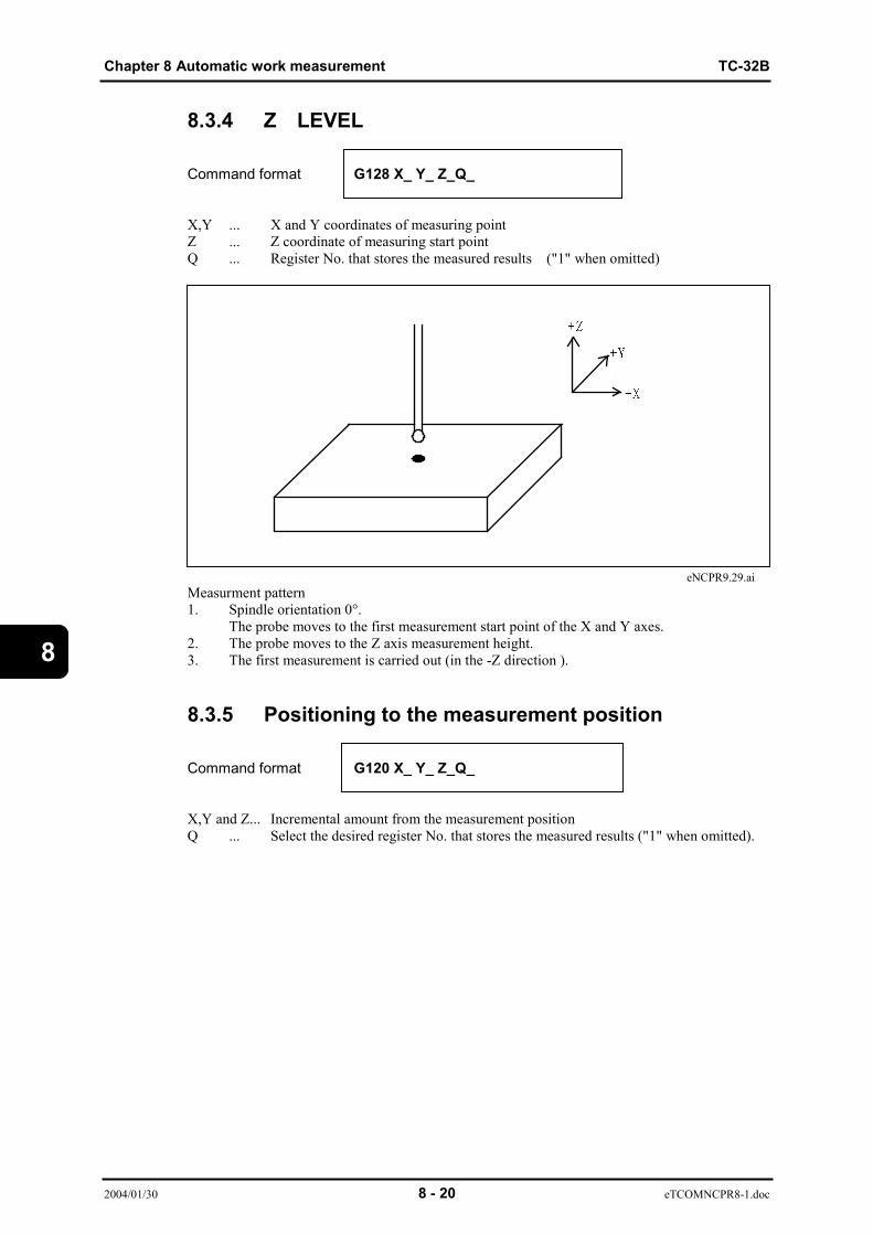
Chapter 8 Automatic work measurement TC-32B
2004/01/30 8 - 20 eTCOMNCPR8-1.doc
8
8.3.4 Z LEVEL
Command format G128 X_ Y_ Z_Q_
X,Y ... X and Y coordinates of measuring pointZ ... Z coordinate of measuring start pointQ ... Register No. that stores the measured results ("1" when omitted)
eNCPR9.29.aiMeasurment pattern1. Spindle orientation 0°.
The probe moves to the first measurement start point of the X and Y axes.2. The probe moves to the Z axis measurement height.3. The first measurement is carried out (in the -Z direction ).
8.3.5 Positioning to the measurement position
Command format G120 X_ Y_ Z_Q_
X,Y and Z... Incremental amount from the measurement positionQ ... Select the desired register No. that stores the measured results ("1" when omitted).

TC-32B Chapter 8 Automatic work measurement
2004/01/30 8 - 21 eTCOMNCPR8-1.doc
8
measyrement position
eNCPR9.30.ai
G120 Xa Yb Zc
When [G120 Xa, Yb, and Zc] is commanded, the probe moves to point P.When the measurement data does not exist, NO MEASRUING DATA alarm willoccur.
8.4 Handling of the measured results8.4.1 Display of the measured resultsThe following screen appears when [6] is pressed on the <PRODUCTION MONITOR MENU>screen or the cursor is moved to [6. MEASUREMENT RESULTS] and [ENT] is pressed.
S07005u1.bmp
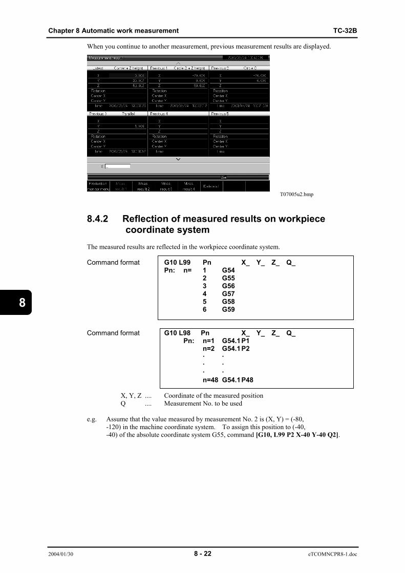
Chapter 8 Automatic work measurement TC-32B
2004/01/30 8 - 22 eTCOMNCPR8-1.doc
8
When you continue to another measurement, previous measurement results are displayed.
T07005u2.bmp
8.4.2 Reflection of measured results on workpiececoordinate system
The measured results are reflected in the workpiece coordinate system.
Command format G10 L99 Pn X_ Y_ Z_ Q_Pn: n= 1 G54
2 G553 G564 G575 G586 G59
Command format G10 L98 Pn X_ Y_ Z_ Q_Pn: n=1 G54.1P1
n=2 G54.1P2· ·· ·· ·n=48 G54.1P48
X, Y, Z .... Coordinate of the measured positionQ .... Measurement No. to be used
e.g. Assume that the value measured by measurement No. 2 is (X, Y) = (-80,-120) in the machine coordinate system. To assign this position to (-40,-40) of the absolute coordinate system G55, command [G10, L99 P2 X-40 Y-40 Q2].
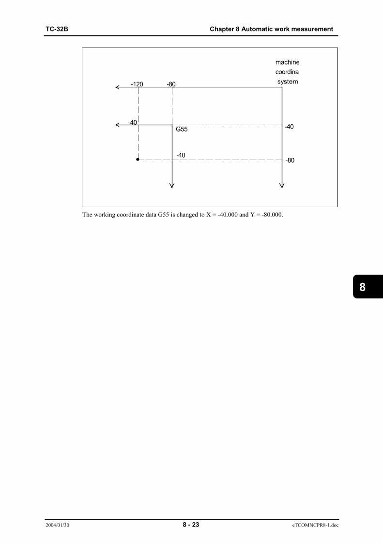
TC-32B Chapter 8 Automatic work measurement
2004/01/30 8 - 23 eTCOMNCPR8-1.doc
8
The working coordinate data G55 is changed to X = -40.000 and Y = -80.000.
-120
-80
-40G55
-40
-80
-40
machinecoordinat system

Chapter 8 Automatic work measurement TC-32B
2004/01/30 8 - 24 eTCOMNCPR8-1.doc
8
8.5 Lock key operationsDRY RUNThe probe moves to the measurement start point, but measurement is not carried out.Measurement data is not transferred, either.MACHINE LOCKAxes are not moved. The coordinate value on the<POSITION> screen varies.
RESTARTWhen G121 to G129 are commanded during restarting, RESTART ERROR will occur.
TC-32B Chapter 9 High Accuracy Mode A
2004/01/22 9 - 1 eT32BNCPR.9.doc
9
CHAPTER 9
HIGH ACCURACY MODE A
1 Outline2 Usage3 Restrictions4 Effective Functions
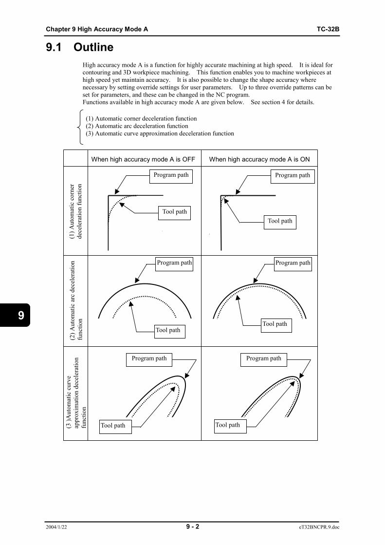
Chapter 9 High Accuracy Mode A TC-32B
2004/1/22 9 - 2 eT32BNCPR.9.doc
9
9.1 OutlineHigh accuracy mode A is a function for highly accurate machining at high speed. It is ideal forcontouring and 3D workpiece machining. This function enables you to machine workpieces athigh speed yet maintain accuracy. It is also possible to change the shape accuracy wherenecessary by setting override settings for user parameters. Up to three override patterns can beset for parameters, and these can be changed in the NC program.Functions available in high accuracy mode A are given below. See section 4 for details.
(1) Automatic corner deceleration function (2) Automatic arc deceleration function (3) Automatic curve approximation deceleration function
Program path
Tool pathTool path
Program path
Tool path
Program path
Tool path
Program path
Tool path
When high accuracy mode A is OFF When high accuracy mode A is ON
(1) A
utom
atic
cor
ner
dece
lera
tion
func
tion
(2) A
utom
atic
arc
dec
eler
atio
nfu
nctio
n
(3 )A
utom
atic
cur
veap
prox
imat
ion
dece
lera
tion
func
tion
Tool path
Program path
Program path

TC-32B Chapter 9 High Accuracy Mode A
2004/01/22 9 - 3 eT32BNCPR.9.doc
9
9.2 Usage9.2.1 User parameter settingHigh accuracy mode A has three deceleration functions. Adjusting the settings for userparameters (Corner deceleration override, Arc deceleration override, Curve approximationdeceleration override) alters the shape accuracy. In addition to this, up to three patterns (levels 1to 3) can be set for parameters, and these can be changed in the NC program. Each level iscontrolled in reference to the corresponding settings shown below.
M code Level User parameter (switch 1)Corner deceleration override 1Arc deceleration override 1M260 1Curve approximation deceleration override 1Corner deceleration override 2Arc deceleration override 2M261 2Curve approximation deceleration override 2Corner deceleration override 3Arc deceleration override 3M262 3Curve approximation deceleration override 3

Chapter 9 High Accuracy Mode A TC-32B
2004/1/22 9 - 4 eT32BNCPR.9.doc
9
9.2.2 User parameter descriptionParameter name Descriptions Setting range (%)
Corner decelerationoverride 1
Set the automatic corner deceleration override for level 1(M260) in high accuracy mode A.When 100 is set, automatic corner deceleration is performedusing the machine’s unique deceleration rate.When a value higher than 100 is set, the deceleration ratedecreases and machining time is shortened.When a value lower than 100 is set, accuracy improves.When 0 is set, automatic corner deceleration is notperformed.
10 ~ 1000
Arc decelerationoverride 1
Set the automatic arc deceleration override for level 1(M260) in high accuracy mode A.When 100 is set, automatic arc deceleration is performedusing the machine’s unique deceleration rate.When a value higher than 100 is set, the deceleration ratedecreases and machining time is shortened.When a value lower than 100 is set, accuracy improves.When 0 is set, automatic arc deceleration is not performed.
10 ~ 1000
Curve approximationdeceleration override 1
Set the automatic curve approximation deceleration overridefor level 1 (M260) in high accuracy mode A.When 100 is set, automatic curve approximationdeceleration is performed using the machine’s uniquedeceleration rate.When a value higher than 100 is set, the deceleration ratedecreases and machining time is shortened.When a value lower than 100 is set, accuracy improves.When 0 is set, automatic curve approximation deceleration isnot performed.
10 ~ 1000
Corner decelerationoverride 2
Set the automatic corner deceleration override for level 2(M261) in high accuracy mode A.The function is the same as level 1.
10 ~ 1000
Arc decelerationoverride 2
Set the automatic arc deceleration override for level 2(M261) in high accuracy mode A.The function is the same as level 1.
10 ~ 1000
Curve approximationdeceleration override 2
Set the automatic curve approximation deceleration overridefor level 2 (M261) in high accuracy mode A.The function is the same as level 1.
10 ~ 1000
Corner decelerationoverride 3
Set the automatic corner deceleration override for level 3(M262) in high accuracy mode A.The function is the same as level 1.
10 ~ 1000
Arc decelerationoverride 3
Set the automatic arc deceleration override for level 3(M262) in high accuracy mode A.The function is the same as level 1.
10 ~ 1000
Curve approximationdeceleration override 3
Set the automatic curve approximation deceleration overridefor level 3 (M262) in high accuracy mode A.The function is the same as level 1.
10 ~ 1000
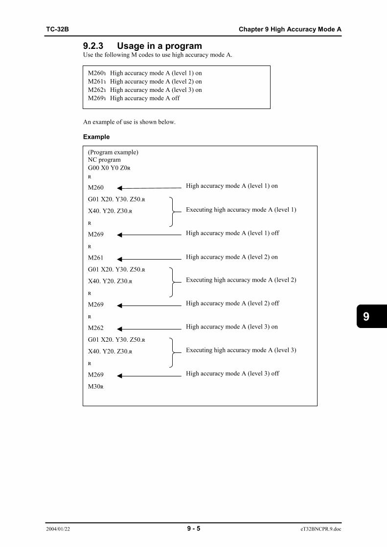
TC-32B Chapter 9 High Accuracy Mode A
2004/01/22 9 - 5 eT32BNCPR.9.doc
9
9.2.3 Usage in a programUse the following M codes to use high accuracy mode A.
An example of use is shown below.
Example
M260:High accuracy mode A (level 1) onM261:High accuracy mode A (level 2) onM262:High accuracy mode A (level 3) onM269:High accuracy mode A off
(Program example)NC programG00 X0 Y0 Z0;;
M260
G01 X20. Y30. Z50.;
X40. Y20. Z30.;
;
M269
;
M261
G01 X20. Y30. Z50.;
X40. Y20. Z30.;
;
M269
;
M262
G01 X20. Y30. Z50.;
X40. Y20. Z30.;
;
M269
M30;
Executing high accuracy mode A (level 1)
High accuracy mode A (level 1) on
High accuracy mode A (level 1) off
High accuracy mode A (level 2) on
High accuracy mode A (level 3) on
High accuracy mode A (level 2) off
High accuracy mode A (level 3) off
Executing high accuracy mode A (level 2)
Executing high accuracy mode A (level 3)

Chapter 9 High Accuracy Mode A TC-32B
2004/1/22 9 - 6 eT32BNCPR.9.doc
9
9.2.4 Conditions availableG code modal conditions*1) must be as below to use high accuracy mode A. The conditionsbelow are current when the power is turned on.
*1) See the Instruction Manual for check method of G code modal conditions.
9.2.5 Conditions where high accuracy mode A is releasedHigh accuracy mode A is turned off if any of the following operations is performed while highaccuracy mode A is on.
(1) Power is turned on. (2) The [RST] key is pressed. (3) Any operation that resets memory operation is performed.
(e.g. The [Z.RTN] key is pressed in manual mode.) (4) End of program (M02, M03) is executed.
G64:Cutting modeG67:Macro cancelG80:Canned cycle cancel

TC-32B Chapter 9 High Accuracy Mode A
2004/01/22 9 - 7 eT32BNCPR.9.doc
9
9.3 Restrictions9.3.1 Functions availableFunctions that can be used while high accuracy mode A is on are given below.1. All M codes2. C codes in the table below.
G code Function G code Function0 Positioning 51 Scaling1 Linear interpolation 51.1 Mirror image2 Arc (CW) 52 Local coord. system setting3 Arc (CCW) 53 Machine coord. system selection4 Dwell 54 Workpiece coord. system selection 19 Exact stop (one shot) 54.1 ~ Extended workpiece coord. system
selection10 Programmable data input 55 Workpiece coord. system selection 212 Circular cutting CW 56 Workpiece coord. system selection 313 Circular cutting CCW 57 Workpiece coord. system selection 417 XY plane selection 58 Workpiece coord. system selection 518 ZX plane selection 59 Workpiece coord. system selection 619 YZ plane selection 64 Cutting mode22 Programmable stroke limit valid 65 Macro call23 Programmable stroke limit invalid 68 Rotational transformation28 Reference position return 69 Rotational transformation cancel29 Return from reference position 80 Canned cycle cancel30 2nd to 6th reference position return 90 Absolute command36 Coordinate calculation function (bolt
hole)91 Incremental command
37 Coordinate calculation function (line(angle))
92 Workpiece coord. system setting
38 Coordinate calculation function (line(X, Y))
94 Initial position return
39 Coordinate calculation function (line(grid))
98 Minute feed
40 Cutter compensation cancel 99 R-point return41 Cutter compensation left 100 Tool change42 Cutter compensation right 102 XZ circular interpolation CW43 Tool length offset + 103 XZ circular interpolation CCW44 Tool length offset - 168 Rotation transformation using meas.
result49 Tool length offset cancel 202 YZ circular interpolation CW50 Scaling cancel 203 YZ circular interpolation CCW
50.1 Mirror image cancel
9.3.2 Additional axis travel commandWhen additional axis travel command is used while high accuracy mode A is on, high accuracymode A is released temporarily during additional axis travel.In addition, commands that move the feed axis and additional axis simultaneously by cutting feed(G01, G02, G03) cannot be used.

Chapter 9 High Accuracy Mode A TC-32B
2004/1/22 9 - 8 eT32BNCPR.9.doc
9
9.4 Effective FunctionsThe functions below are available while high accuracy mode A is on.
(1) Automatic corner deceleration function (2) Automatic arc deceleration function (3) Automatic curve approximation deceleration function
9.4.1 Automatic corner deceleration functionWhen machining a corner, the actual tool path gradually deviates from the program path as thetool approaches the corner. This results in an error. In addition to this, the error becomes largeras the feed rate increases at the corner.This function automatically decelerates the feed rate only around the corner according to thecorner deceleration override setting so that the corner shape accuracy specified by the NC programis maintained.The setting range of the corner deceleration override is 0%, or 10% to 1000% (100% is thedefault).The smaller the setting, the more effective the deceleration function, minimizing error andimproving shape accuracy.When 0% is entered, the automatic corner deceleration function is turned off.The graph below shows the accuracy relative to the corner deceleration override setting.
How to read graph:Accuracy at corner when 100% is set for corner deceleration override is "1".
[1] Corner deceleration override (100% ~ 1000%)
② Corner deceleration override (10% ~ 100%)Corner deceleration override and accuracy
0.01.0
2.0
3.0
4.0
5.0
6.0
7.0
8.0
9.0
10.0
100 200 300 400 500 600 700 800 1000Corner deceleration override (%)
Goo
dAc
cura
cyPo
or
Corner deceleration override and accuracy
0.0
0.1
0.2
0.3
0.4
0.5
0.6
0.7
0.8
0.9
1.0
0 10 20 30 40 50 60 70 80 90 100Corner deceleration override (%)
Goo
dAc
cura
cyPo
or
[2] Corner deceleration override (10% ~ 100%)
900
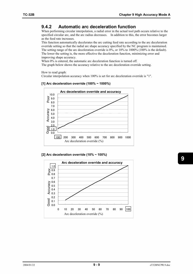
TC-32B Chapter 9 High Accuracy Mode A
2004/01/22 9 - 9 eT32BNCPR.9.doc
9
9.4.2 Automatic arc deceleration functionWhen performing circular interpolation, a radial error in the actual tool path occurs relative to thespecified circular arc, and the arc radius decreases. In addition to this, the error becomes largeras the feed rate increases.This function automatically decelerates the arc cutting feed rate according to the arc decelerationoverride setting so that the radial arc shape accuracy specified by the NC program is maintained.The setting range of the arc deceleration override is 0%, or 10% to 1000% (100% is the default).The lower the setting is, the more effective the deceleration function, minimizing error andimproving shape accuracy.When 0% is entered, the automatic arc deceleration function is turned off.The graph below shows the accuracy relative to the arc deceleration override setting.
How to read graph:Circular interpolation accuracy when 100% is set for arc deceleration override is "1".
[1] Arc deceleration override (100% ~ 1000%)
[2] Arc deceleration override (10% ~ 100%)
Arc deceleration override and accuracy
0.01.0
2.0
3.0
4.0
5.0
6.0
7.0
8.0
9.0
10.0
100 200 300 400 500 600 700 800 900 1000
Arc deceleration override and accuracy
0.0
0.1
0.2
0.3
0.40.5
0.6
0.7
0.8
0.9
1.0
0 10 20 30 40 50 60 70 80 90 100
Arc deceleration override (%)
Arc deceleration override (%)
Goo
dAc
cura
cyPo
orG
ood
Accu
racy
Poor

Chapter 9 High Accuracy Mode A TC-32B
2004/1/22 9 - 10 eT32BNCPR.9.doc
9
9.4.3 Automatic curve approximation decelerationThis function automatically decelerates the curve approximation block feed rate according to thecurve approximation deceleration override setting so that the shape accuracy for the curveapproximation block (curve composed of minute blocks) specified by the NC program ismaintained.The setting range of the curve approximation deceleration override is 0%, or 10% to 1000%(100% is the default).The lower the setting is, the more effective the deceleration function, minimizing error andimproving shape accuracy.When 0% is entered, the automatic curve approximation deceleration function is turned off.The graph below shows the accuracy relative to the curve approximation deceleration overridesetting.
How to read graph:An error for curve approximation block when 100% is set for curve approximation decelerationoverride is "1".
[1] Curve approximation deceleration override (100% ~ 1000%)
[2] Curve approximation deceleration override (10% ~ 100%)
Curve approximation deceleration override andaccuracy
0.0
1.0
2.0
3.0
4.0
5.0
6.0
7.0
100 200 300 400 500 600 700 800 900 1000
Curve approximation deceleration override (%)
Curve approximation deceleration override andaccuracy
0.0
0.1
0.2
0.3
0.4
0.5
0.6
0.7
0.8
0.9
1.0
0 10 20 30 40 50 60 70 80 90 100
Curve approximation deceleration override(%)
Goo
dAc
cura
cyPo
orG
ood
Accu
racy
Poor
TC-32B Chapter10 Subprogram function
2004/01/16 10 - 1 eTCOMNCPR10-1.doc
10
CHAPTER 10
SUBPROGRAM FUNCTION
10.1 Making Subprogram10.2 Simple Call10.3 Return No. Designation from Sub Program

Chapter10 Subprogram function TC-32B
2004/01/16 10 - 2 eTCOMNCPR10-1.doc
10
10 Function of SubprogramWhen a program contains fixed sequences or frequently repeated patterns, these sequences orpatterns may be entered into the memory as a subprogram.The subprogram can be called out in the memory operation mode.A subprogram called by the main program can also call another subprograms.Max 8 fold nesting is available.
eNCPR11.01.ai
One calling command can call a subprogram repeatedly.
10.1 Making SubprogramGenerally, a subprogram is made by the following format.
(Note 1) Specify M99 at the last block of subprogram.(Note 2) If another G or M code is commanded in the M99 block, an alarm is
generated.The axis movement is not available even by commanding X, Y or Zaddress.
main program sub program A sub program
sub program A sub program B calling calling
M99; M99
M99 ;
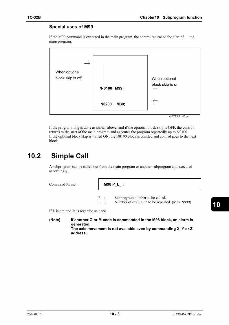
TC-32B Chapter10 Subprogram function
2004/01/16 10 - 3 eTCOMNCPR10-1.doc
10
Special uses of M99
If the M99 command is executed in the main program, the control returns to the start of themain program.
eNCPR11.02.ai
If the programming is done as shown above, and if the optional block skip is OFF, the controlreturns to the start of the main program and executes the program repeatedly up to N0100.If the optional block skip is turned ON, the N0100 block is omitted and control goes to the nextblock.
10.2 Simple CallA subprogram can be called out from the main program or another subprogram and executedaccordingly.
Command format M98 P_L_ ;
P : Subprogram number to be called.L : Number of execution to be repeated. (Max. 9999)
If L is omitted, it is regarded as once.
(Note) If another G or M code is commanded in the M98 block, an alarm isgenerated.The axis movement is not available even by commanding X, Y or Zaddress.
/N0100 M99;
N0200 M30;
When optionalblock skip is off; When optional
block skip is on

Chapter10 Subprogram function TC-32B
2004/01/16 10 - 4 eTCOMNCPR10-1.doc
10
10.3 Return No. Designation from Program
Command format M99 P_ ;
10.3.1 Command by sub program(Program execution sequence )When the command is executed, the program returns the commanded sequence No.of theparent program. The sequence No is serched from the top of the program,and the programreturns to the block initially found.An alarm will occur when the commanded sequence No.is not present.
eNCPR11.03.ai
(Note) An alarm will occur unless the number of repeats commanded by M98 is “1”.
10.3.2 Command by main programWhen the command is executed the program to the sequence No. commanded within the mainprogram. The sequence No.is searched from the top of the program ,and the program jump to theblock initially found.An alarm will occur when the commanded sequence No. is not present.
(Program execution sequence )
eNCPR11.04.ai
M98 P_ ;
N0001 ;
M99 P0001 ;
G01 Z_ ;
N0001 ;
M99 P0001 ;
TC-32B Chapter11 Feed function
2004/01/22 11 - 1 eTCOMNCPR11-1.doc
11
CHAPTER 11
FEED FUNCTION
Chapter11 Feed function TC-32B
2004/01/22 11 - 2 eTCOMNCPR11-1.doc
11
11 Feed FunctionFeedrate is specified by the number following address F.
(1) Command rangeMetric system : 1~999999 mm/min
1~999999゜/minInch system : 0.1~99999.9 inch/min
0.1~99999.9゜/min
(2) ClampIf the axis movement at a higher feedrate than the values specified by the machine parameter, analarm is generated.

TC-32B Chapter12 S,T,M function
2004/01/22 12 - 1 eTCOMNCPR12.doc
12
CHAPTER 12
S,T,M FUNCTION
12. 1 S Function12. 2 T Function12. 3 M Function

Chapter12 S,T,M function TC-32B
2004/01/22 12 - 2 eTCOMNCPR12.doc
12
12 S,T,M FunctionBy commanding the following functions, machine motions other than the axismovements are available.S : Spindle speed commandT : Tool magazine number commandM : ON/OFF command of various solenoids of the machine
12.1 S FunctionThe S code is used for specifying the spindle speed.The spindle speed is specified by the address S and a following within 5-digit number.
(Note 1)The S command is not cancelled by the NC reset function, but it becomes zerowhen the power is turned ON.(Note 2)The S command should be always given before commanding the spindle rotation(M03,M04)(Note 3)When the S command is in the same block as that of axis movement, the Scommand becomes effective at the same time the axis movement starts.
12.2 T FunctionWhen commanded, the magazine rotates to the corresponding pot.
Three commanded forms are provided as below.
12.2.1 Commanded by tool No.Command format T_ _ _;
Commanded by tool No. after “T” (T1-T99), and the pot with the corresponding tool attached isIndexed.
12.2.2 Commanding by pot No.(magazine No.)Commanding by pot No.Commanded the pot number (magazine number) using the two digit numerical values after “T1”,and the pot with the corresponding tool attached is indexed. (T101-T 1nn , “nn” indicates themaximum numbers of the attached pots.)
12.2.3 Commanded by group No.Commanded the group number using the two digit numerical value after “T9”( T901-T930), and the pot with the corresponding tool attached is indexed.
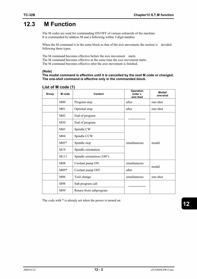
TC-32B Chapter12 S,T,M function
2004/01/22 12 - 3 eTCOMNCPR12.doc
12
12.3 M FunctionThe M codes are used for commanding ON/OFF of various solenoids of the machine.It is commanded by address M and a following within 3-digit number. When the M command is in the same block as that of the axis movement, the motion is devidedfollowing three types.
The M command becomes effective before the axis movement starts.The M command becomes effective at the same time the axis movement starts.The M command becomes effective after the axis movement is finished.
(Note)The modal command is effective until it is cancelled by the next M code or changed.The one-shot command is effective only in the commanded block.
List of M code (1)Group M code Content
Operationorder v.
axis feedModal/
one-shot
M00 Program stop after one-shot
M01 Optional stop after one-shot
M02 End of program
M30 End of program
M03 Spindle CW
M04 Spindle CCW
M05* Spindle stop
M19 Spindle orientation
M111 Spindle orientation (180°)
simultaneous modal
M08 Coolant pump ON simultaneous
M09* Coolant pump OFF aftermodal
M06 Tool change simultaneous one-shot
M98 Sub program call
M99 Return from subprogram
The code with * is already set when the power is turned on.
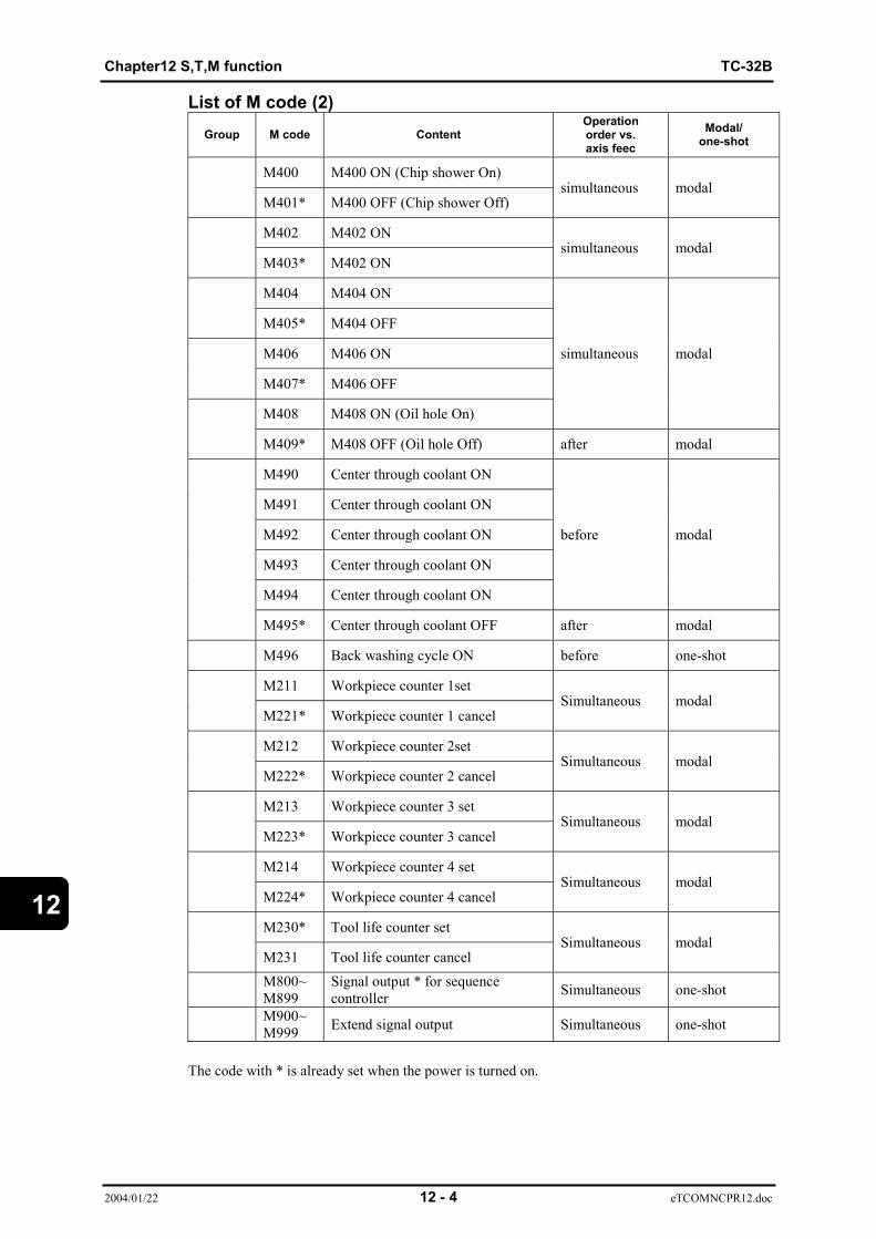
Chapter12 S,T,M function TC-32B
2004/01/22 12 - 4 eTCOMNCPR12.doc
12
List of M code (2)Group M code Content
Operationorder vs.axis feec
Modal/one-shot
M400 M400 ON (Chip shower On)
M401* M400 OFF (Chip shower Off)simultaneous modal
M402 M402 ON
M403* M402 ONsimultaneous modal
M404 M404 ON
M405* M404 OFF
M406 M406 ON
M407* M406 OFF
M408 M408 ON (Oil hole On)
simultaneous modal
M409* M408 OFF (Oil hole Off) after modal
M490 Center through coolant ON
M491 Center through coolant ON
M492 Center through coolant ON
M493 Center through coolant ON
M494 Center through coolant ON
before modal
M495* Center through coolant OFF after modal
M496 Back washing cycle ON before one-shot
M211 Workpiece counter 1set
M221* Workpiece counter 1 cancelSimultaneous modal
M212 Workpiece counter 2set
M222* Workpiece counter 2 cancelSimultaneous modal
M213 Workpiece counter 3 set
M223* Workpiece counter 3 cancelSimultaneous modal
M214 Workpiece counter 4 set
M224* Workpiece counter 4 cancelSimultaneous modal
M230* Tool life counter set
M231 Tool life counter cancelSimultaneous modal
M800~M899
Signal output * for sequencecontroller Simultaneous one-shot
M900~M999 Extend signal output Simultaneous one-shot
The code with * is already set when the power is turned on.

TC-32B Chapter12 S,T,M function
2004/01/22 12 - 5 eTCOMNCPR12.doc
12
List of M code (3)Group M code Content
Operationorder vs.axis feed
Modal/one-shot
M120 TOUCH signal check after one-shot
M121 TOUCH signal check after one-shot
M200 Tool breakage detection(with return motion) after one-shot
M201 Tool breakage detection after one-shot
M320 Measurement device sensor ONconfirmation one-shot
M321 Measurement device sensor OFFconfirmation one-shot
M350 Thermal displacementcompensation (X) before one-shot
M351 Thermal displacementcompensation (Y) before one-shot
M352 Thermal displacementcompensation (Z) before one-shot
M353 Thermal displacementcompensation (XYZ) before one-shot
M438 Magazine cover open
M439 Magazine cover closesimultaneous one-shot
M251 Tap time constant control
M252* Tap acceleration constant controlsimultaneous modal
M260 High precision mode A ON(Level 1)
M261 High precision mode A ON(Level 2)
M262 High precision mode A ON(Level 3)
M269* High precision mode A OFF
simultaneous modal
M270 Positioning finish check distancesetting off
M271~M279
Positioning finish check distancesetting
simultaneous modal
M410 Index of the pallet 2 to the outside
M411 Index of the pallet 1 to the outsideone-shot
M430 Pallet (C axis) unclamp
M431* Pallet (C axis) clampmodal
M435* Magazine rotation maximum speed
M436 Magazine rotation speed 1
M437 Magazine rotation speed 2
simultaneous modal
M501~M599
Magazine rotation for tool settingposition simultaneous one-shot
The code with * is already set when the power is turned on.
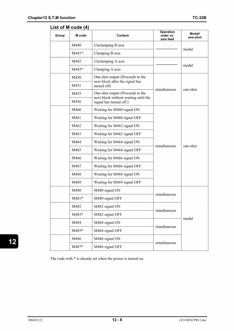
Chapter12 S,T,M function TC-32B
2004/01/22 12 - 6 eTCOMNCPR12.doc
12
List of M code (4)Group M code Content
Operationorder vs.axis feed
Modal/one-shot
M440 Unclamping B axis
M441* Clamping B axismodal
M442 Unclamping A axis
M443* Clamping A axismodal
M450
M451
One-shot output (Proceeds to thenext block after the signal hasturned off)
M455
M456
One-shot output (Proceeds to thenext block without waiting until thesignal has turned off.)
simultaneous one-shot
M460 Waiting for M460 signal ON
M461 Waiting for M460 signal OFF
M462 Waiting for M462 signal ON
M463 Waiting for M462 signal OFF
M464 Waiting for M464 signal ON
M465 Waiting for M464 signal OFF
M466 Waiting for M466 signal ON
M467 Waiting for M466 signal OFF
M468 Waiting for M468 signal ON
M469 Waiting for M469 signal OFF
simultaneous one-shot
M480 M480 signal ON
M481* M480 signal OFFsimultaneous
M482 M482 signal ON
M483* M482 signal OFFsimultaneous
M484 M484 signal ON
M485* M484 signal OFFsimultaneous
M486 M486 signal ON
M487* M486 signal OFFsimultaneous
modal
The code with * is already set when the power is turned on.
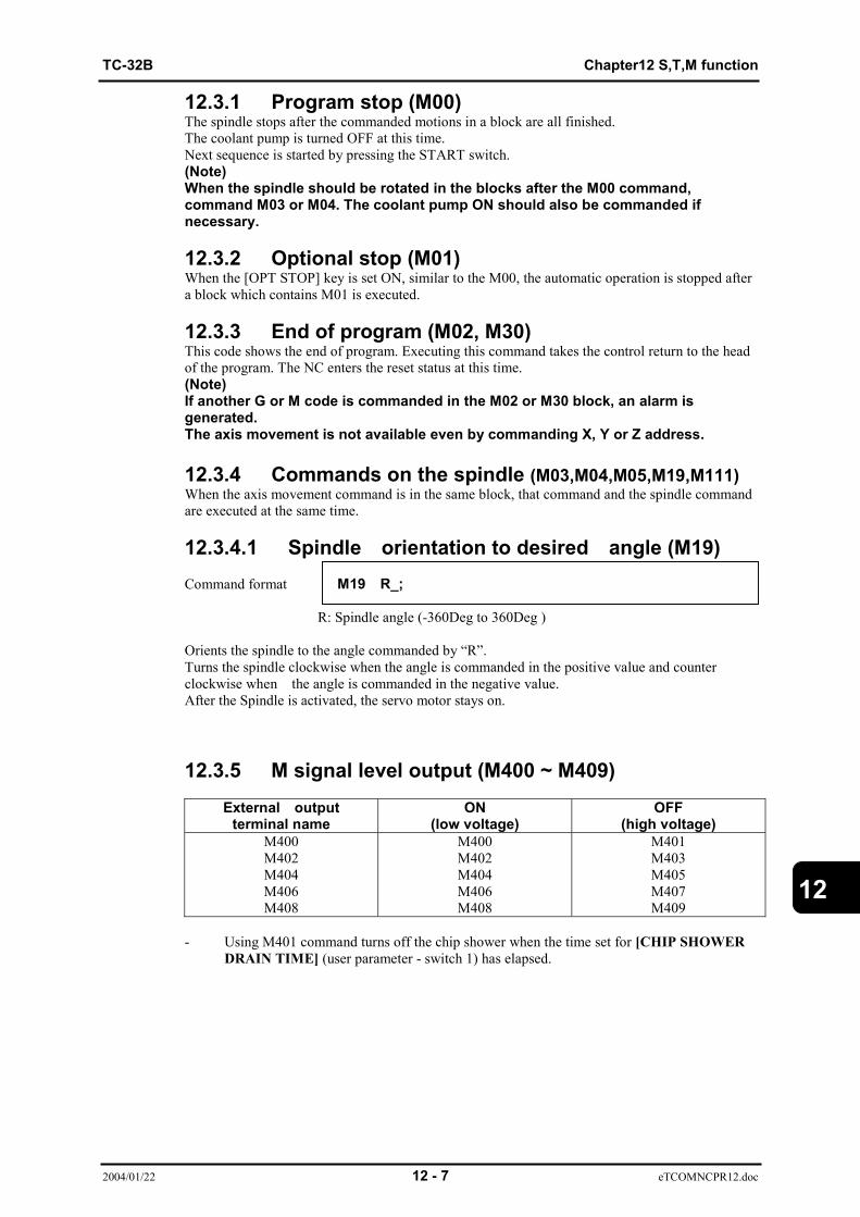
TC-32B Chapter12 S,T,M function
2004/01/22 12 - 7 eTCOMNCPR12.doc
12
12.3.1 Program stop (M00)The spindle stops after the commanded motions in a block are all finished.The coolant pump is turned OFF at this time.Next sequence is started by pressing the START switch.(Note)When the spindle should be rotated in the blocks after the M00 command,command M03 or M04. The coolant pump ON should also be commanded if necessary.
12.3.2 Optional stop (M01)When the [OPT STOP] key is set ON, similar to the M00, the automatic operation is stopped aftera block which contains M01 is executed.
12.3.3 End of program (M02, M30)This code shows the end of program. Executing this command takes the control return to the headof the program. The NC enters the reset status at this time.(Note)If another G or M code is commanded in the M02 or M30 block, an alarm isgenerated.The axis movement is not available even by commanding X, Y or Z address.
12.3.4 Commands on the spindle (M03,M04,M05,M19,M111)When the axis movement command is in the same block, that command and the spindle commandare executed at the same time.
12.3.4.1 Spindle orientation to desired angle (M19)Command format M19 R_;
R: Spindle angle (-360Deg to 360Deg )
Orients the spindle to the angle commanded by “R”.Turns the spindle clockwise when the angle is commanded in the positive value and counterclockwise when the angle is commanded in the negative value.After the Spindle is activated, the servo motor stays on.
12.3.5 M signal level output (M400 ~ M409)External output
terminal nameON
(low voltage)OFF
(high voltage)M400M402M404M406M408
M400M402M404M406M408
M401M403M405M407M409
- Using M401 command turns off the chip shower when the time set for [CHIP SHOWERDRAIN TIME] (user parameter - switch 1) has elapsed.
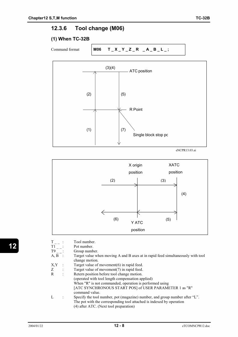
Chapter12 S,T,M function TC-32B
2004/01/22 12 - 8 eTCOMNCPR12.doc
12
Y ATC
position
12.3.6 Tool change (M06)
(1) When TC-32B
Command format M06 T _ X _ Y _ Z _ R _ A _ B _ L _ ;
eNCPR13.03.ai
T _ _ : Tool number.T1 _ _ : Pot number.T9 _ _ : Group number.A, B : Target value when moving A and B axes at in rapid feed simultaneously with tool
change motion.X,Y : Target value of movement(6) in rapid feed.Z : Target value of movement(7) in rapid feed.R : Retern position before tool change motion.
(operated with tool length compensation applied)When "R" is not commanded, operation is performed using[ATC SYNCHRONOUS START POS] of USER PARAMETER 1 as "R" command value.
L : Specify the tool number, pot (magazine) number, and group number after “L”.The pot with the corresponding tool attached is indexed by operation(4) after ATC. (Next tool preparation)
ATC position
R Point
Single block stop po(1)
(2)
(3)(4)
(5)
(7)
X origin
position
XATC
position
(2)
(6)
(3)
(5)
(4)

TC-32B Chapter12 S,T,M function
2004/01/22 12 - 9 eTCOMNCPR12.doc
12
Operations(1) Tool moves to the Z-axis point "R" while performing 0-degree spindle
orientation. When "T" is commanded, magazine swivels.(2) Tool movement to theZ-axis ATC origin, to the X axis origin point and to Y axis
ATC position, A, B axes movement to the the commanded value and also maga zine cover opening occur simultaneously.
(3) Tool moves to theX-axis ATC position.(4) Arm swivels to change tool.
Tool change motion differs depending on setting on [MAGAZINE TOOL] screen. Refer tothe "Tool Change Motion" for detailes.
(5) Tool movement to the X axis orgin point and Z axis point "R" and magazine coverclosing occurs stimultaneously.
(6) XY axes moves to the commanded value.(7) Tool moves to Z-axis commanded position.
Caution- When performing cycle operation, tool moves in cutting mode
between operations (1)and (6). And tool moves in position checkmode.For XY positioning at operation (2) and (3) ( from X:origin Y: ATC toX axis positioning (ATC position)) ,tool moves in cutting mode when Yaxis positions at the ATC position before X axis does.
- When [RESET] key or [STOP SWITCH] key is pressed at operations(2), machine stops after Z axis movement to ATC origin point.For X, Y, A, and B axes movement, machine stops immediately.
- When [RESET] key or [STOP SWITCH] key is pressed betweenoperations (3) and (5) , machine stops after motion (5) is completed.For the operation (2), A, and B axes movement, machine stopsimmediately.
- Machine does not stop if single block occurs between operations (2) and (6) .- For operation (5), machine goes to the next opeation after closing the
magazine cover witho6ut checking if the magazine cover is closed.- Modes can not be switched between operation (1) and (6).- All data other than M06 can be omitted. However, code "T" must be
commanded once by operator before M06 is commanded.- Tool offset is canceled when M06 is commanded. Further, tool
length compensation is canceled from operation (2).- When tool offset (G41 or G42) and X and Y axes movement are commanded to
block M06, tool offset begins when X and Y axes movement (6 commences.Start-up is performed in format 1, regardless of6 parameters.
- When tool offset is commanded to block M06, tool offset becomes valid fromoperation (5) .
- When M06 is commanded while tool length compensation (G49) iscanceled, operation (1) is performed subject to [ATC REFERENCETOOL LENGTH] selection for user parameter.When tool offset is not commanded to block M06, operations (5) areperformed subject to [ATC REFERENCE TOOL LENGTH] selection foruser parameter.
- Alarm appears when code M other than spindle command iscommanded to block M06.Alarm appears when axis A or B is commanded while optional A andB axes are not in use.
- When point "R" command position (5) is lower than Z axis commandposition (7), tool moves to Z-axis commanded position, and operation(7) is not performed.

Chapter12 S,T,M function TC-32B
2004/01/22 12 - 10 eTCOMNCPR12.doc
12
Tool change motionTool change motion differs depending on tool type set on [MAGAZINE TOOL] screen.(When large tool is not set on [MAGAZINE TOOL])The following sequence is performed:(1) Pot raises.(2) Magazine swivels.(3) Pot lowers.(4) Arm swivels at high speed.
(When large tool is set on [MAGAZINE TOOL])Tool change from standard tool to standard tool, and large tool to large tool.The following sequence is performed:(1) Pot raises.(2) Magazine swivels.(3) Pot lowers.(4) Arm swivels.(5) Pot raises.When pot is already at upper limit before tool change motion commences, sequence starts from(2).
When ((4) arm swivels) changing from large tool to large tool, arm swivels at low speed.When ((4) arm swivels) changing from standard tool to standard tool, arm swivels at high speed.
Tool change from large tool to standard tool or vice versa.
The following sequence is performed:(1) Pot raises.(2) Magazine swivels. (Empty pot is indexed.)(3) Pot lowers.(4) Arm swivels.(5) Pot raises.(6) Magazine swivels. (Specified pot is indexed.)(7) Pot lowers.(8) Arm swivels.(9) Pot raises.When pot is already at upper or lower limit before tool change motion commences, sequence startsfrom (3) or (4), respectively.
For operation (2), empty pot is indexed appropriately for large tool and standard tool.
Arm swivels ((4) or (8)) at low speed when large tool is to be changed, and at high speed whenstandard tool is to be changed.
Notes1) If empty pot for large tool is not available when change from large tool to
standard tool is attempted, [*NO EMPTY POT] alarm appears.2) If empty pot for standard tool is not available when change from standard tool
to large tool is attempted, [*NO EMPTY POT] alarm appears.

TC-32B Chapter12 S,T,M function
2004/01/22 12 - 11 eTCOMNCPR12.doc
12
Next tool preparation
Next tool preparation is performed after the arm has swiveled or the pot has risen afterthe arm swivels in the ATC sequence.When ATC is not performed, only next tool preparation is performed.Next tool preparation is not performed when the next tool is already indexed.
The next tool preparation sequence differs depending on the type of tool set on themagazine tool screen.
When large tool is not set on [MAGAZINE TOOL].(1) Pot rises(2) Magazine swivels(3) Pot lowersNext tool preparation ends when the above sequence is completed.The sequence starts from (2) when the pot is already at the upper limit before next toolpreparation commences.
When large tool is set on [MAGAZINE TOOL].Both spindle tool and next tool are standard or large(1) Pot rises(2) Magazine swivels(3) Pot lowersNext tool preparation ends when the above sequence is completed.The sequence starts from (2) when the pot is already at the upper limit before next toolpreparation commences.
Spindle tool is standard and next tool is large or vice versa(1) Pot rises(2) Magazine swivels (empty pot is indexed)(3) Pot lowersNext tool preparation ends when the above sequence is completed.The sequence starts from (2) when the pot is already at the upper limit before next toolpreparation commences.
Note 1) When the next tool is changed from a large tool to a standard tool andthere is no empty pot for a large tool, the [NO EMPTY POT] error occurs.
Note 2) When the next tool is changed from a standard tool to a large tool andthere is no empty pot for a standard tool, the [NO EMPTY POT] erroroccurs.
Chapter12 S,T,M function TC-32B
2004/01/22 12 - 12 eTCOMNCPR12.doc
12
12.3.7 Workpiece counter specification (M211~M214)When M211~M214 are specified to the counter 1~4 respectively, and M211 ~ M214are commanded in the memory operation, the commanded counter counts up byspecified step at the execution of M02 or M30.The counter specification is cancelled when the power is turned ON, the [RESET]key is pressed, M02 or M30 is executed, the operation is reset or M221~M224(counter cancel) is commanded.(Ex.) When the counter 1 counts 1 and the counter 2 counts 2, execution of M211and M212 by the operation program makes the counter 1 count up 1, the counter 2count up 2.(Note) M211~ M214 can be commanded during MDI operation.
12.3.8 Workpiece counter cancel (M221~M224)M221~M224 command cancellation of the counter 1~ 4 respectively.When M221~M224 are commanded in the memory operation or MDI operation,relative counter specificaton is cancelled.
12.3.8.1 Tool life counterExecute command M231 to interrupt counting the service life of the tool attached to the spindle.Execute command M230 to resume counting.
12.3.9 Automatic corner deceleration (M232, M233)- This function is valid for commands that perform continuous XY-axes cutting movement.- Automatic corner deceleration does not apply during tool compensation.
12.3.10 Tool breakage detection (M120 and M121)When the M120 command is given, the input signal TOUCH (touch sensor) is checked.If this is ON, operation is ended. If this is OFF, a tool breakage error is generated and the TOOL(tool error) signal is output.M121 command, if this is OFF for finishing the check. If this is ON, a tool breakage error isgenerated.
12.3.11 Tool breakage detection (M200 and M201)Operation procedures are described in Option, Tool Breakage Detection Unit in theInstruction Manual.

TC-32B Chapter12 S,T,M function
2004/01/22 12 - 13 eTCOMNCPR12.doc
12
12.3.12 Tap time constant selection (M241 to 250)- When the M251 command is given, tap time stay constant when tapping of Z-axis speed .- When the M251 command is given, tap acceleration stay constant when tapping of Z-axis
speed.
12.3.13 Pallet related M codes(M410, M411, M430, and M431)
This function is available for QT mounted machine.- When command M410 is executed, the Z-axis is returned to its origin and then the C-axis is
indexed to -180° (pallet 2 is positioned outside).- When command M411 is executed, the Z-axis is returned to its origin and then the C-axis is
indexed to 0° (pallet 1 is positioned outside).- When command M430 is executed, the C-axis unclamped by override.- When command M431 is executed, the C-axis clamped by override.
12.3.14 Unclamping and clamping C axis(M430 and M431)
This function is available for QT mounted machine.- When M430 is commanded, the C axis is unclamped. Unclamping and clamping C axis is
not automatically controlled afterward.- When M431 is commanded, the C axis is clamped. Unclamping and clamping C axis is
automatically controlled afterward.
This command is valid when C is set to operate using the mashine paramater and the clampmerchanism is set to [1:Type2]or[2:Type3].An alarm will occur in other cases.
12.3.15 Unclamping and clamping B axis (M440 and M441)- When M440 is commanded, the B axis is unclamped. Unclamping and clamping B axis
is not automatically controlled afterward.- When M441 is commanded, the B axis is clamped. Unclamping and clamping B axis is
automatically controlled afterward.This command is valid when B is set to operate using the mashine paramater and theclamp merchanism is set to [1:Type2]or[2:Type3].An alarm will occur in other cases.
12.3.16 Unclamping and clamping A axis (M442 and M443)- When M442 is commanded, the A axis is unclamped. Unclamping and clamping A axis is
not automatically controlled afterward.- When M443 is commanded, the A axis is clamped. Unclamping and clamping A
axis is automatically controlled afterward.
This command is valid when A is set to operate using the mashine paramater and theclamp merchanism is set to [1:Type2]or[2:Type3].An alarm will occur in other cases.
12.3.17 One-shot output (M450, M451, M455, and M456)- M450 and M451 commands proceed to the next block after output time has passed and the
signal has turned off.- M455 and M456 commands proceed to the next block without waiting until the signal turns
off.- The signal output time is set by user parameter 1.

Chapter12 S,T,M function TC-32B
2004/01/22 12 - 14 eTCOMNCPR12.doc
12
12.3.18 Waiting until response is given (M460 to M469)For example- M460 command waits until M460 signal turns on.- M461 command waits until M460 signal turns off- M462 command waits until M462 signal turns on.- M463 command waits until M462 signal turns off.- M464 command waits until M464 signal turns on.- M465 command waits until M464 signal turns off.- M466 command waits until M466 signal turns on.- M467 command waits until M466 signal turns off.- M468 command waits until M468 signal turns on.- M469 command waits until M468 signal turns off.
The maximum waiting time is set by MAXIMUM TIME OF EXT SIGNAL of userparameter 1.If the actual time has exceeded the preset time, an alarm occurs.
12.3.19 Magazine rotate speed (M435 to M437)Arm style of ATC machine is changeable the program for magazine rotate speed.- M435 : Magazine rotate maximum speed.- M436 : Magazine rotate speed 1.- M437 : Magazine rotate speed 2.Return to the maximum speed to follow the operation below. Command M435.
Finish the program.Reset the driving.Tool changing.
M436, M437 rotate speed:Set “Magazine rotate speed 1(M436).” “Magazine rotate speed 2 (M437).” in the user parameter.
12.3.20 Magazine rotate to tool setting position (M501 to M599)
- M5** : Rotate the magazine to set pot position that ** specified the tool number ofsetting position
12.3.21 Positioning finished check distance
(M270 to M279)- M270 : Positioning finished check distance, positioning finished angle non-specific.- M271 : User parameter of “M271Positioning finished check distance” and “M271
Positioning finished angle” value to be the imposition width for positioning.X, Y, Z axes use the value of “Positioning finished check distance”.A, B, C axes use the value of “Positioning finished angle”.
- M272~M279 : As same as M271.Return to the “Positioning finished check distance”, “Positioning finished angle non-specific” tofollow the operation below. Command M270.
Finish the program.Reset the driving.

TC-32B Chapter13 Option
2004/01/22 13 - 1 eTCOMNCPR13-1.doc
13
CHAPTER 13
OPTION
13.1 Programming Precautions When Using Rotation Axis (index table)

Chapter13 Option TC-32B
2004/01/22 13 - 2 eTCOMNCPR13-1.doc
13
13.1 Programming Precautions When UsingRotation Axis (index table)When using the QT table on the TC-31A, 32A, and R2A with the rotation axis installed, be sure toplace the rotation axis positioning command before the cutting command in the program file.

eT32BNCPROKU

eT32BNCPROKU
6A34680010401(1)