Embed Size (px)
DESCRIPTION
Nepal NBC code
Citation preview

N E P A L N A T I O N A L B U I L D I N G C O D E
DRAFT FINAL NBC 205: 2012
READY TO USE GUIDELINE FOR DETAILINGS OF LOW RISE REINFORCED CONCRETE BUILDINGS
WITHOUT MASONRY INFILL
Government of NepalMinistry of Urban Development
Department of Urban Development and Building ConstructionBabar Mahal, Kathmandu, NEPAL
2070

N E P A L N A T I O N A L B U I L D I N G C O D E
DRAFT FINAL NBC 205 : 2012
READY TO USE GUIDELINE FOR DETAILINGS OF LOW RISE REINFORCED CONCRETE
BUILDINGS WITHOUT MASONRY INFILL
Gf]kfn ;/sf/ -dlGqkl/ifb\_ sf] ldlt sf] lg0f{ofg';f/ :jLs[t
Government of NepalMinistry of Urban Development
Department of Urban Development and Building ConstructionBabar Mahal, Kathmandu, NEPAL
This publication represents a standard of good practice and thereforetakes the form of recommendations. Compliance with it does not conferimmunity from relevant legal requirements, including bylaws

NBC205, 2013 March, 2013
i
Preface to the first edition
This Nepal Standard was prepared during 1993 as part of a project to prepare a draft NationalBuilding Code for Nepal.
In 1988 the Ministry of Housing and Physical Planning (MHPP), conscious of the growingneeds of Nepal's urban and shelter sectors, requested technical assistance from the UnitedNations Development Programme and their executing agency, United Nations Centre forHuman Settlements (UNCHS).
A programme of Policy and Technical Support was set up within the Ministry (UNDP ProjectNEP/88/054) and a number of activities have been undertaken within this framework.
The 1988 earthquake in Nepal, and the resulting deaths and damage to both housing andschools, again drew attention to the need for changes and improvement in current buildingconstruction and design methods.
Until now, Nepal has not had any regulations or documents of its own setting out eitherrequirements or good practice for achieving satisfactory strength in buildings.
In late 1991 the MHPP and UNCHS requested proposals for the development of suchregulations and documents from international organizations in response to terms of referenceprepared by a panel of experts.
This document has been prepared by the subcontractor's team working within the Departmentof Building, the team including members of the Department and the MHPP. As part of theproposed management and implementation strategy, it has been prepared so as to conformwith the general presentation requirements of the Nepal Bureau of Standards and Metrology.
The subproject has been undertaken under the aegis of an Advisory Panel to the MHPP.
The Advisory Panel consisted of :
Mr. UB Malla, Joint Secretary, MHPPChairma
n Director General, Department of Building(Mr. LR Upadhyay) Member
Mr. AR Pant, Under Secretary, MHPPMembe
r Director General, Department of Mines & Geology(Mr. PL Shrestha) Member
Director General, Nepal Bureau of Standards & Metrology(Mr. PB Manandhar) Member
Dean, Institute of Engineering, Tribhuvan University(Dr. SB Mathe) Member
Project Chief, Earthquake Areas Rehabilitation &Reconstruction Project MemberPresident, Nepal Engineers Association MemberLaw Officer, MHPP (Mr. RB Dange) MemberRepresentative, Society of Consulting Architectural &

NBC205, 2013 March, 2013
ii
Engineering Firms (SCAEF) MemberRepresentative, Society of Nepalese Architects (SONA) MemberDeputy Director General, Department of Building,
(Mr. JP Pradhan) Member-Secretary
The Subcontractor was BECA WORLEY INTERNATIONAL CONSULTANTS LTD. of NewZealand in conjunction with subconsultants who included:
Golder Associates Ltd., CanadaSILT Consultants P. Ltd., NepalTAEC Consult (P.) Ltd., NepalUrban Regional Research, USA
Principal inputs to this standard came from :
Dr. AS Arya, University of Roorkee Mr.JK Bothara, TAECMr. YK Parajuli, TAECMr. AM Dixit, SILTMr. AM Tuladhar, DoB, HMGNDr. RD Sharpe, BECA (Team Leader)
Revisions and Updated to this code came from:
Mr. Purna P. Kadariya, DG, DUDBCMr. Kishore Thapa, DDG, DUDBCMr. Mani Ratna Tuladhar, Sr. Div. Engineer, DUDBCMr. Jyoti Prasad Pradhan, Ex. DG, DOBMr. Bhubaneswor Lal Shrestha, Ex. DDG, DOBMr. Uttam Shrestha, Architect, Architects' Module Pvt. Ltd.Mr. Manohar Lal Rajbhandrai, Sr. Structural Engineer, MR Associates Mr.Amrit Man Tuladhar, Civil Engineer, DUDBC

NBC205, 2013 March, 2013
iii
Preface to the second edition
……………………………………………………………………………..………………………………………………………………………………..
Should be written by DUDBC

NBC205, 2013 March, 2013
iv
TABLE OF CONTENTS
0. Foreword........................................................................................................................................ 60..1 Introduction ....................................................................................................................... 60..2 Objective ........................................................................................................................... 60..3 Limitations ........................................................................................................................ 6
1 Scope.............................................................................................................................................. 11.1 General .............................................................................................................................. 11.2 Related Standards.............................................................................................................. 1
2 Interpretation.................................................................................................................................. 22.1 General .............................................................................................................................. 22.2 Terminology...................................................................................................................... 22.3 Symbols............................................................................................................................. 4
3 Selection and Investigation of Site................................................................................................ 53.1 General .............................................................................................................................. 53.2 Use of Local Knowledge .................................................................................................. 53.3 Site Investigation Requirements ....................................................................................... 53.4 Allowable Bearing Pressure.............................................................................................. 5
4 The Building Structure .................................................................................................................. 74.1 Description ........................................................................................................................ 74.2 Restrictions on the Structural Layout ............................................................................... 7
5 Construction Materials .................................................................................................................. 95.1 Concrete ............................................................................................................................ 95.2 Brickwork.......................................................................................................................... 95.3 Reinforcing Steel Bars .................................................................................................... 10
6 Design Procedure......................................................................................................................... 116.1 Procedure Outline ........................................................................................................... 116.2 Total Horizontal Seismic Base Shear ............................................................................. 11
6.2.1 Design Seismic Coefficient............................................................................... 126.3 Distributing Total Horizontal Seismic Base Shear......................................................... 12
7 Design of the Frames................................................................................................................... 137.1 Frames ............................................................................................................................. 137.3 Frame Design .................................................................................................................. 13
7.3.1 Basis of Recommendations .............................................................................. 137.3.2 Recommended Members Sizes and Minimum Reinforcement ................... 14

NBC205, 2013 March, 2013
v
8 Reinforcing Non-load Bearing Walls.......................................................................................... 388.1 Between Framing Columns.......................................................................................... 38
8.1.1 Solid Walls......................................................................................................... 388.1.2 Walls with Openings ........................................................................................ 38
8.2 Outside Framing Columns.............................................................................................. 38
9 Parapets........................................................................................................................................ 449.1 General ........................................................................................................................... 449.2 Flower Pots...................................................................................................................... 44

NBC205, 2013 March, 2013
vi
0. Foreword
0. 1 Introduction
For the last 30 to 35 years there has been a proliferation of reinforced concrete(RC) framed buildings constructed in the urban and semi-urban areas of Nepal.Most of these buildings have been built on the advice of mid-level techniciansand masons without any professional structural design input. These buildingshave been found to be significantly vulnerable to a level of earthquake shakingthat has a reasonable chance of happening in Nepal. Hence, these buildings,even though built with modern materials, could be a major cause of loss of lifein future earthquakes. Upgrading the structural quality of future buildings ofthis type is essential in order to minimise the possible loss of life due to theirstructural failure.
0. 2 Objective
The main objective of these Ready to Use Detailing Guideline (RUD) is toprovide ready-to-use dimensions and details for various structural and non-structural elements for up to three-storey reinforced concrete (RC), framed,ordinary residential buildings commonly being built by owner-builders inNepal.
This RUD is intended to cater primarily to the requirements of mid-leveltechnicians (overseers and draughtspersons) who are not trained to undertakeindependently the structural design of buildings. However Engineers can alsouse it for reference and cross check their design output.
0.3 Limitations
The requirements set forth in this guideline shall be applicable for ordinarybuildings as per clause 4.0. The intention is to achieve a minimum acceptablestructural safety, even though it is always preferable to undertake specificinvestigations and design.Owners and builders must use the services of competent professionaldesigners for buildings not covered by these guidelines.
1
NBC201V2.RV7 April 201230 October 1994
1 Scope
1.1 General
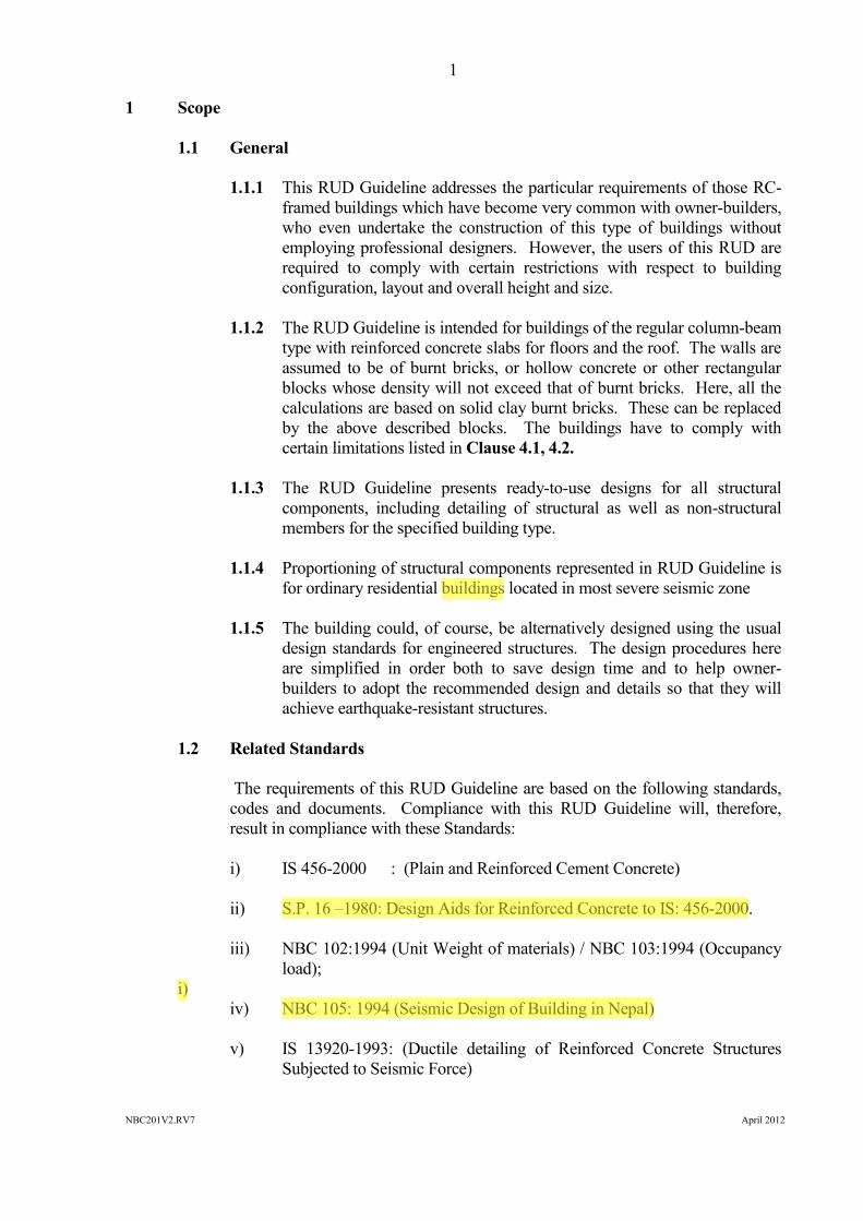
1.1.1 This RUD Guideline addresses the particular requirements of those RC-framed buildings which have become very common with owner-builders,who even undertake the construction of this type of buildings withoutemploying professional designers. However, the users of this RUD arerequired to comply with certain restrictions with respect to buildingconfiguration, layout and overall height and size.
1.1.2 The RUD Guideline is intended for buildings of the regular column-beamtype with reinforced concrete slabs for floors and the roof. The walls areassumed to be of burnt bricks, or hollow concrete or other rectangularblocks whose density will not exceed that of burnt bricks. Here, all thecalculations are based on solid clay burnt bricks. These can be replacedby the above described blocks. The buildings have to comply withcertain limitations listed in Clause 4.1, 4.2.
1.1.3 The RUD Guideline presents ready-to-use designs for all structuralcomponents, including detailing of structural as well as non-structuralmembers for the specified building type.
1.1.4 Proportioning of structural components represented in RUD Guideline isfor ordinary residential buildings located in most severe seismic zone
1.1.5 The building could, of course, be alternatively designed using the usualdesign standards for engineered structures. The design procedures hereare simplified in order both to save design time and to help owner-builders to adopt the recommended design and details so that they willachieve earthquake-resistant structures.
1.2 Related Standards
The requirements of this RUD Guideline are based on the following standards,codes and documents. Compliance with this RUD Guideline will, therefore,result in compliance with these Standards:
i) IS 456-2000 : (Plain and Reinforced Cement Concrete)
ii) S.P. 16 –1980: Design Aids for Reinforced Concrete to IS: 456-2000.
iii) NBC 102:1994 (Unit Weight of materials) / NBC 103:1994 (Occupancyload);
i)iv) NBC 105: 1994 (Seismic Design of Building in Nepal)
v) IS 13920-1993: (Ductile detailing of Reinforced Concrete StructuresSubjected to Seismic Force)
2
NBC201V2.RV7 April 201230 October 1994
2 Interpretation
2.1 General
2.1.1 In this RUD Guideline, the word `shall' indicates a requirement that is tobe adopted in order to comply with the provision of this guideline, whilethe word `should' indicates recommended practice.
2.1.2 References to `Code' indicate Seismic Design of Buildings in Nepal(NBC 105:1994, ,NBC110:1994).
2.1.3 Words implying the singular only also include the plural and vice versawhere the context requires this.
2.2 Terminology
2.2.0. In this Standard, unless inconsistent with the context, the followingdefinitions shall apply:
2.2.1. THROUGH BARS means the bars that shall run continually parallel tothe walls of a beam to form a cage. The minimum number of through bars in abeam shall not be less than 4.0.
2.2.2. EXTRA BARS means the longitudinal bars that shall be provided inaddition to through bars at supports as top bars and bottom bars and at mid-span asbottom bars of a beam.
2.2.3. CHAIR means an element made of steel bar which is used to maintainthe vertical distances between top and bottom bars in slabs.
2.2.4. DEAD LOAD means the weight of all permanent components of abuilding including walls, partitions, columns, beams, floors, roofs, finishes andfixed plant and fittings that are an integral part of the structure.
2.2.5. DESIGN means use of rational computational or experimental methodsin accordance with the established principles of structural mechanics.
2.2.6. FRAME means a system composed of interconnected beams andcolumn members functioning as a complete self-contained unit with or without theaid of horizontal diaphragms or floor-bracing systems.
2.2.7. IMPORTANT BUILDINGS means those buildings which either housefacilities essential before and after a disaster (eg., hospitals, fire and police stations,communication centres, etc.), or which by their very purpose have to house largenumbers of people at one time (eg., cinema halls, schools, convention centres, etc.),or which have special national and international importance (eg., palaces, etc.), orwhich house hazardous facilities (eg., toxic or explosive facilities, etc.).

3
NBC201V2.RV7 April 201230 October 1994
2.2.8. LANDSLIDE means the downward and outward movement of slope-forming materials.
2.2.9. LIQUEFACTION means the phenomenon in which relatively loose,saturated sandy soils lose a large proportion of their strength under seismic shaking.
2.2.10. LEVEL OF LOCAL RESTRAINT means the level at which theground motion of the earthquake is transmitted to the structure by interactionbetween the foundation materials and the foundation elements by friction andbearing.
2.2.11. LIVE LOAD means the load assumed or known to result from theoccupancy or use of a building and includes the loads on floors, loads on roofsother than wind, loads on balustrades and loads from movable goods, machinery,and plant that are not an integral part of the structure and may be changed duringthe life of the building with a resultant change in floor or roof loading.
2.2.12. LUMPED MASS means the theoretical concentration of the mass ofadjacent upper and lower half storeys at any floor level.
2.2.13. MASONRY INFILL WALL means any structural wall constructed inbrick with cement sand mortar inside the frame and intended to carry horizontalload by equivalent compression strut action.
2.2.14. NON-LOAD BEARING WALL means any wall which is not intendedto carry any significant external loads and which functions just as a cladding,partition wall or filler wall.
2.2.15. ORDINARY BUILDING means any building which does not lie on animportant building category as per clause 2.2.7 (eg., residential, generalcommercial, ordinary offices, etc.).
2.2.16.
2.2.17. STOREY means the space between two adjacent floors or platforms.

4
NBC201V2.RV7 April 201230 October 1994
2.3 Symbols
A Maximum horizontal length of building
As Area of steel bar
B Maximum horizontal width of building
Cd Design seismic coefficient
D Lateral stiffness of column
fck Characteristic compressive strength of concrete
Fi Horizontal seismic force applied at level i
fy Characteristic strength of steel
hi Height of the level i above the lateral restraint imposed by ground
K1, K2 Plan length of structural wings
K Steel grade Fe500 (high-strength, TMT)
Kc Stiffness ratio of column (moment of inertial divided by itslength)
l Centre-to-centre span of beam
M Steel grade Fe250 (mild steel)
RC Reinforced cement concrete
te Thickness at the edge of the pad foundation
tm Maximum thickness of the pad foundation
T Steel grade Fe415 (high-strength, cold-worked)
V Total horizontal seismic base shear
Vij Horizontal load carried by a column line j at level i
Wi Proportion of the Wt at a particular level i
Wt Total of the vertical dead loads and appropriate live loads abovethe level of lateral restraint provided by the ground
Diameter of steel bar

5
NBC201V2.RV7 April 201230 October 1994
3 Selection and Investigation of Site
3.1 General
This section sets out some of the requirements to be considered during siteselection for the construction of buildings in order to minimise the risks to thebuildings from primary geological as well as secondary seismic hazards such asfault rupture, landslides and liquefaction. A building shall not be constructed asper this guidelines if the proposed site is:
- Water-logged- A rock-falling area- A landslide-prone area- A subsidence and/or fill area- A river bed or swamp area
3.2 Use of Local Knowledge
It is a good practice during the construction of a building to examine the existinglocal knowledge and the history of the performance of existing buildings. Thiswill assist in identifying whether there is any danger from inherent naturalsusceptibilities of the land to the processes of sliding, erosion, land subsidenceand liquefaction during the past earthquakes or any other natural/geologicalprocesses likely to threaten the integrity of the building. The local practice ofmanaging such hazards, if any, should be judged against the required level ofacceptable risk (life safety).
3.3 Site Investigation Requirements
Site exploration shall be carried out by digging test pits, two as a minimum, andmore if the subsurface soil condition shows a significant variation in soil type.
Generally, the minimum depth of exploration for a building covered by this RUDshall be 2 m. In hilly areas, exploration up to the depth of sound bed-rock, if itlies shallower than 2 m, should suffice.
No exploration shall be required if the site is located on rock or on fluvialterraces (Tar) with boulder beds.
The soils encountered in the test pits should be classified as per Table 3.1.
3.4 Allowable Bearing Pressure
The allowable bearing pressure that can be used is given in Table 3.1 inconjunction with the visual classification of the subsurface soil type.

6
NBC201V2.RV7 April 201230 October 1994
TABLE 3.1 : FOUNDATION SOIL CLASSIFICATION AND SAFE BEARINGCAPACITY
Type of Foundation MaterialsFoundationClassification
Presumed SafeBearingCapacity, kN/m2
1. Rocks in different state ofweathering, boulder bed,gravel, sandy gravel and sand-gravel mixture, dense or loosecoarse to medium sandoffering high resistance topenetration when excavated bytools, stiff to medium claywhich is readily indented witha thumb nail.
Hard 200
2. Fine sand and silt (dry lumpseasily pulverised by thefinger), moist clay and sand-clay mixture which can beindented with strong thumbpressure
Medium 150 and< 200
3. Fine sand, loose and dry; softclay indented with moderatethumb pressure
Soft 100 and< 150
4. Very soft clay which can bepenetrated several centimetreswith the thumb, wet clays
Weak 50 and< 100

7
NBC201V2.RV7 April 201230 October 1994
4 The Building Structure
4.1 Description
The structure is a reinforced concrete frame without any contribution of masonryinfill walls in resisting the vertical or seismic loads. The frame shall comply withClause 4.1, 4.2 and be designed to resist earthquake forces as a bare frame.
4.2 Restrictions on the Structural Layout
For a structure to be built using this RUD Guideline, it shall comply with therestrictions set out below. If the structure does not comply, it must be designedin accordance with the Standards referred to in Clause 1.2 or latest appropriatestandard.
[Note: 1. A is longer side of Building and B is shorter side of building2. Openings can be provided as per functional/architectural requirements.
3. Foundation is not shown.]
Figure 4.1: Restrictions in Reinforced Concrete Frame
CONDITIONS FOR DETAILED DIMENSIONSA and B ≤ 25.0 mA ≤ 3 x Ba x b ≤ 13.5 sq. m.a, b ≤ 4.5 ma, b ≥ 2.1 mA or B ≤ 6 bays
8
NBC201V2.RV7 April 201230 October 1994
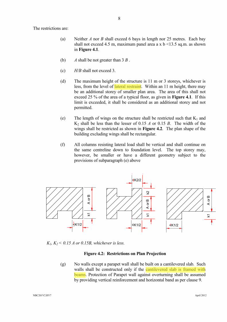
The restrictions are:
(a) Neither A nor B shall exceed 6 bays in length nor 25 metres. Each bayshall not exceed 4.5 m, maximum panel area a x b <13.5 sq.m. as shownin Figure 4.1.
(b) A shall be not greater than 3 B .
(c) H/B shall not exceed 3.
(d) The maximum height of the structure is 11 m or 3 storeys, whichever isless, from the level of lateral restraint. Within an 11 m height, there maybe an additional storey of smaller plan area. The area of this shall notexceed 25 % of the area of a typical floor, as given in Figure 4.1. If thislimit is exceeded, it shall be considered as an additional storey and notpermitted.
(e) The length of wings on the structure shall be restricted such that K1 andK2 shall be less than the lesser of 0.15 A or 0.15 B. The width of thewings shall be restricted as shown in Figure 4.2. The plan shape of thebuilding excluding wings shall be rectangular.
(f) All columns resisting lateral load shall be vertical and shall continue onthe same centreline down to foundation level. The top storey may,however, be smaller or have a different geometry subject to theprovisions of subparagraph (e) above
K1, K2 < 0.15 A or 0.15B, whichever is less.
Figure 4.2: Restrictions on Plan Projection
(g) No walls except a parapet wall shall be built on a cantilevered slab. Suchwalls shall be constructed only if the cantilevered slab is framed withbeams. Protection of Parapet wall against overturning shall be assumedby providing vertical reinforcement and horizontal band as per clause 9.
a1
a2
a3
a4
a5
b3b2
b1
A
B
h1h2
h3h4
H
REINFORCED CONCRETE FRAME
POSSIBLE SINGLESTOREY PENTHOUSE
Figure 4.1 : Reinforced Concrete Frame
Figure 4.2 : Restrictions on Plan Projections
<K1/2
k1A
or B
<K1/2
k1A
or B
k2
<K2/2
k1A
or B
<K1/2
CONDITIONS FOR DETAILED DIMENSIONSA and B > 25.0 mB/3 < A < 3 x Ba x b > 13.5 sq. m.a b > 4.5 mA or B > 6 bays
Note : 1. Opening in structural infill walls restricted, in other as per functional / architectural requirements. 2. Foundation is not shown.
K1, K2 < 0.25 A or 0.25 B, whichever is less.

9
NBC201V2.RV7 April 201230 October 1994
(h) The foundation shall be at a uniform level.
(i) Buildings shall not have a soft storey.
(j) The size of cantilever projection should not exceed 1 metre.
5 Construction Materials
5.1 Concrete
The concrete to be used in footings, columns, beams and slabs, etc., shall have aminimum crushing strength of 20 N/mm² (Nominal mix, 1:1.5:3) at 28 days for a150 mm cube.
Cement: Cement shall be as fresh as possible. Any cement stored for more thantwo months from the date of receipt from the factory should either be avoided ortested and used only if the test results are found to be satisfactory. Any cementwhich has deteriorated or hardened shall not be used. All cement used shall beOrdinary Portland Cement meeting the requirements of NS: 049-2041 orPozzolona Portland Cement (PPC) meeing the requirement of NS: 385-2054. Itis advisable to use cement which has obtained the NS mark if independent testsare not carried out.
Coarse Aggregates: Coarse aggregates shall consist of crushed or broken stoneand shall be hard, strong, dense, durable, clean, of proper grading and free fromany coating likely to prevent the adhesion of mortar. The aggregate shall begenerally angular in shape. As far as possible, flaky, elongated pieces shall beavoided. The aggregate shall conform to the requirements of NS: 305-2050 andNS: 297-2050.
The coarse aggregates shall be of following sizes:
(a) Normal cement concrete with a thickness of 100 mm and above - gradedfrom 20 mm downwards
(b) Cement concrete from 40 mm to 100 mm thick - graded from 12 mmdownwards
Sand: Sand shall consist of a siliceous material having hard strong, durable,uncoated particles. It shall be free from undesirable amounts of dust lumps, softor flaky particles, shale, salts, organic matter, loam, mica or other deleterioussubstances. In no case shall the total of all the undesirable substances exceedfive percent by weight. The sand shall confirm to the requirements of NS: 51-204.
5.2 Brickwork
The brick masonry shall be built with the usually specified care regarding pre-soaking of bricks in water, level bedding of planes fully covered with mortar,vertical joints broken from course to course and their filling with mortar fully.

10
NBC201V2.RV7 April 201230 October 1994
Bricks: The bricks shall be of a standard rectangular shape, burnt red, hand-formed or machine-made, and of crushing strength not less than 3.5 N/mm². Thehigher the density and the strength, the better they will be. The standard bricksize of 230 x 115 x 57 mm with 10 mm thick horizontal and vertical mortar jointsis preferable. Tolerances of -10 mm on length, -5 mm on width and ±3 mm onthickness shall be acceptable for the purpose of thick walls in this RUD. Thebrick shall confirm to the requirements of NS: 01-2035.
Wall Thickness: A minimum thickness of one half-brick and a maximumthickness of one brick shall be used.
Mortar: Cement-sand mixes of 1:6 and 1:4 shall be adopted for one-brick andhalf-brick thick walls, respectively. The addition to the mortars of smallquantities of freshly hydrated lime in a ratio of ¼ to ½ of the cement will greatlyincrease their plasticity without reducing their strength. Hence, the addition oflime within these limits is encouraged.
Plaster: All plasters should have a cement-sand mix not leaner than 1:6. Theyshall have a minimum 28 days cube crushing strength of 3 N/mm².
5.3 Reinforcing Steel Bars
Reinforcing steel shall be clean and free of loose mill-scale, dust, loose rust andcoats of paints, oil, grease or other coatings, which may impair or reduce bond.It shall conform to the following NS standards.
High-strength deformed bars conforming to NS: 191-2046 with fy = 415 N/mm²shall be used for reinforcing all masonry and concrete.
However, high strength deformed steel bars, produced by the thermo-mechanical treatment process, of grades Fe 500 , having elongation more than14.5 percent and conforming to other requirements of IS 1786:2008 / NS: 191-2046 may also be used for the reinforcement. (Ref. IS 13920; Cl 5.3)
[Note: 1. in the presentation of this RUD Guidelines, fy = 415 N/mm², 500 N/mm²steel is assumed for main bars in beams and columns. For using anyother steel with lower values of fy, the steel area shall becorrespondingly increased.

11
NBC201V2.RV7 April 201230 October 1994
6 Design Procedure Adopted
6.1 Procedure Outline
The simplified design procedure comprises the following stages:
a) Conforming that the building plan meets the structural layout restrictions (Clause 4.1,4.2).
b) Calculation of total horizontal seismic base shear on the building using 500 yearsreturn period response spectrum
c) Preparations of 3D numerical model of the building
d) Distribution of total horizontal seismic base shear up the height of the building (Clause6.3).
e) Developing Envelop force diagram of beam and design of beam as per NBC: 110-1994f) Design of Column for outputs of critical load combinationsg) Check for strong column weak beam actionsh) Check for joint shear force
i) Detailing of the structural elements :
i. The frame, beam and column (Clauses 7.1 – 7.3)ii. Recommendation for minimum Sizes and reinforcement (Clause 7.3.2)
j) Reinforcing of non-load-bearing walls (Section 8)
k) Reinforcing of parapets (Section 9)l) Reinforcing of foundations
6.2 Total Horizontal Seismic Base Shear
The sample building structure was designed to withstand a total horizontalseismic base shear, V, calculated in accordance with the formula:
V = Cd x Wt (6.1)Where,
Wt is the combination of the total vertical dead load and 25 % of the liveloads above the level of lateral restraint provided by the ground.

12
NBC201V2.RV7 April 201230 October 1994
6.2.1 Design Seismic Coefficient1
The design seismic coefficients, Cd, for the design of frames withoutmasonry in-fills in the various zones are:
Zone A = 0.09 Zone B = 0.08, Zone C = 0.072
Where a building location lies close to a zone boundary so that itsparticular zone is uncertain, then the building was assumed to fall in thezone requiring the higher value of basic seismic coefficient.
The detailing presented in this building code is based upon the Cd =0.09 and generalised for all other zone also.
6.3 Distributing Total Horizontal Seismic Base Shear
The total horizontal base shear, V, shall be distributed up the height of thebuilding in accordance with the formula (refer to Figure 6.1):
i it
itt hW
hWVF (6-2)
Where,
Fi is the load applied at the level designated as i.
Wi is the proportion of Wt at ith level.
hi is the height of level i above of level of lateral restraint imposed by theground.
Figure 6.1: Floor Level Lateral Forces
1 Seismic coefficients are in accordance with NBC 105with modified Responsespectra from 300 year Return period to 500 year return period, for ductile framesof ordinary building on a soft grade of soil.
F3
F2
F4
F1
i th FLOOR
h1
Figure 6.1 : Floor Level Lateral Forces

13
NBC201V2.RV7 April 201230 October 1994
6.4 Preparation of Numerical Model of Building
3Dimennsional Numerical bare frame model was prepared; The Seismic loadevaluated in 6.3 applied at C.G. of each storey with additional eccentricitydefined in NBC105.
7 Design of the Frames
7.1 Frames
All frames are designed:
(a) To support the applied vertical gravity loads (including the weight of thewalls) without assistance from the walls, and
(b) For seismic condition using forces as per Clause 6.1.(c) Design Load combinations for dead load, live load and earthquake load
should be considered as per NBC 105:1994 and NBC110:1994
7.2 Frame Design
The members and joints were then designed in accordance with NBC 110:1994 /IS 456:2000 and IS13920 and detailed to achieve ductile deformations undersevere earthquakes.
The recommendations for member sizes and minimum reinforcement in allcomponents are shown in Figures 7.1 to 7.4. The reinforcement shall alsocomply with the applicable sections.
7.2.1 Basis of Recommendations
The recommended sizes of members and the reinforcement are based onanalysis and calculations of representative models using the followingdata:
Building Occupancy : Ordinary Building
Column Plan Bay Dimension : 3m x 3m to 4.5m x 3.0mBay Nos. : 2 x 2 to 6 x 6
Number of Storeys : up to three plus stair cover
Storey Height
For terai region preferred storey height = 3.35 mFor other region preferred storey height = 2.75 m
Based up on the climate condition any of the option can be usedWall Thicknesses : up to 115 mm thick brick wall
or equivalent for all internal

14
NBC201V2.RV7 April 201230 October 1994
walls and up to 230 mm thickbrick wall or equivalent for allexternal walls
Cantilever Floor Projection : 1.0 m (from centre-line ofbeam)
Concrete mix : M20 (20 N/mm² cubecrushing strength at 28 days)minimum
Reinforcement : Fe415 (minimum yieldstrength = 415 N/mm²),Fe500 (minimum yieldstrength = 500 N/mm²)
Mortar : Minimum 1:4 cement-sandmortar for half-brick thickwall and 1:6 cement-sandmortar for one-brick thick
Bricks : Minimum crushing strength3.5 N/mm²
7.2.2 Recommended Members Sizes and Minimum Reinforcement
SlabRoof and FloorsThickness : 125 mmSteel : 8ϕ (Fe 415) or 8ϕ (Fe 500) bars as shown in
Figure 7.1.
BeamsRoof and floors (both directions)Width : 230 or 2501 mmDepth : 355 mm overall depth including slab
Plinth Tie beam (both directions)Width : 230 mmDepth : 230 mm overall depth
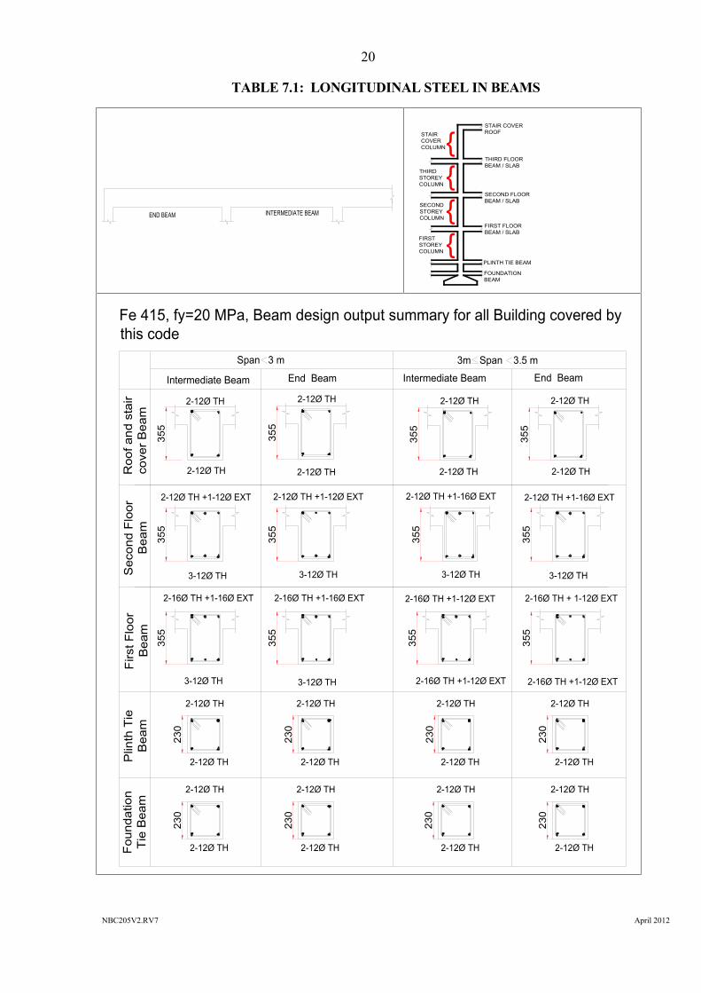
Longitudinal Steel:The top and bottom steel reinforcement bars are given in Table 7.1 for differentspans. The placing of steel shall meet the requirements specified in Figure 7.2.
_____________________________1 Width of beam should be adopted depending on the thickness of wall i.e. as per the
availability of brick sizes.

15
NBC205V2.RV7 April 2012
Figure 7.1 : Slab Reinforcement Details
SLAB PLAN
8Ø (Fe415)- 150
Slab Bottom Continuous/Cranked bars Details along X- and Y-directions
8Ø (Fe415)- 150
staircasevoid
staircasevoid
{0.25b3, Ld}max
{0.15b3, Ld}max
{0.25b2, Ld}max
{0.25b1, Ld}max
{0.25b1, Ld}max
{0.25b2, Ld}max
{0.15a2, Ld}max
{0.25a2, Ld}max {0.25a2, Ld}max8Ø (Fe415)- 150
xx
Y
Y
a1 a2 a3
b3b2
b190
0
B
8Ø (Fe415)- 150
{0.25b1, Ld}max
8Ø (Fe415)- 150{0.15b3, Ld}max
A

16
NBC205V2.RV7 April 2012
Figure 7.1 : Slab Reinforcement Details Continued…….
SLAB PLANTop Extra reinforcement Detail in x-x direction
8Ø (Fe415)- 150
8Ø (Fe415)- 150
8Ø (Fe415)- 150
8Ø (Fe415)- 1508Ø (Fe415)- 150
8Ø (F
e415
)- 15
0
8Ø (Fe415)- 150 8Ø (Fe415)- 1508Ø (Fe415)- 150
8Ø (Fe415)- 300
8Ø (Fe415)- 300 8Ø (Fe415)- 300 8Ø (Fe415)- 300
8Ø (Fe415)- 3008Ø (Fe415)- 300
8Ø (Fe415)- 300 8Ø (Fe415)- 300
8Ø (F
e415
)- 15
0
8Ø (F
e415
)- 15
0
staircasevoid
staircasevoid
{0.15a1, Ld} max {0.3a1, Ld} max {0.3a2, Ld} max
{0.3a3, Ld} max
{0.15a2, Ld} max
{0.3a3, Ld} max{0.3a2, Ld} max{0.15a1, Ld} max{0.15b3,Ld}max
{0.3b3,Ld}max
{0.3b2,Ld}max
{0.3b2,Ld}max
{0.3b1,Ld}max
{0.3b1,Ld}max
x
{0.15b3,Ld}max
{0.15b3,Ld}max
{0.15b1,Ld}max
{0.15b1,Ld}max
x
Y
Y
{0.3a2, Ld} max
{0.3a2, Ld} max
a1 a2 a3
b3b2
b190
0
B
A

17
NBC205V2.RV7 April 2012
Figure 7.1 : Slab Reinforcement Details Continued…….
SLAB PLAN
8Ø (Fe415)- 300 8Ø (Fe415)- 300
Top Extra reinforcement Detail in Y-Y direction
8Ø (Fe415)- 150
8Ø (Fe415)- 150
8Ø (Fe415)- 150
8Ø (Fe415)- 300
8Ø (Fe415)- 150
8Ø (Fe415)- 150
8Ø (Fe415)- 150
8Ø (Fe415)- 150
8Ø (Fe415)- 150
8Ø (Fe415)- 150
8Ø (Fe415)- 300
8Ø (Fe415)- 300
staircasevoid
staircasevoid
{0.3a2,Ld}max {0.3a3,Ld}max{0.3a3,Ld}max
{0.3a1,Ld}max{0.15a1,Ld}max {0.3a2,Ld}max
8Ø (Fe415)- 300
8Ø (Fe415)- 300
{0.3b1,Ld}max
{0.3b2,Ld}max
{0.15,Ld}max
{0.15b1,Ld}max
8Ø (Fe415)- 300 {0.15b3,Ld}max
Y
Y
xx{0.3b1,Ld}max
{0.3,Ld}max
a1 a2 a3
b3b2
b190
0
B
A

18
NBC205V2.RV7 April 2012
Figure 7.1 : Slab Reinforcement Details Continued…….
8Ø (Fe415)- 150A
8Ø (Fe415)- 150
B
{0.3 a2, Ld} max{0.3 a1, Ld} max {0.3 a3, Ld} max{0.3 a2, Ld} max{0.15 a1, Ld} max
{0.25 a2, Ld} max {0.25 a3, Ld} max{0.25 a1, Ld} max {0.25 a2, Ld} max
8Ø (Fe415)-300
Top Extra bar
8Ø (Fe415)- 3008Ø (Fe415)- 300
8Ø (Fe415)- 300Extra top bars
8Ø (Fe415)- 300Extra top bars
8Ø (Fe415)- 300Extra top bars
8Ø (Fe415)- 300 8Ø (Fe415)- 300
{0.15 a1, Ld} max8Ø (Fe415)- 300
8Ø (Fe415)- 300Extra top bars
a1 a2 a3
8Ø (Fe415)- 150 8Ø (Fe415)- 1508Ø (Fe415)- 150 8Ø (Fe415)- 150
8Ø (Fe415)- 1508Ø (Fe415)- 150
8Ø (Fe415)- 150
L- SECTION OF SLAB ALONG X-X DIRECTION
C INTERMEDIATE SLABEND SLAB
8Ø (Fe415)- 150
8Ø (Fe415)- 150
L- SECTION OF SLAB ALONG Y-Y DIRECTION
{0.3 b2, Ld} max{0.3 b1, Ld} max {0.3 b3, Ld} max{0.3 b2, Ld} max {0.15 b3, Ld} max{0.3 b1, Ld} max
{0.15 b3, Ld} max{0.25 b2, Ld} max {0.25 b3, Ld} max{0.25 b1, Ld} max {0.25 b2, Ld} max
8Ø (Fe415)- 150Top Extra bar
8Ø (Fe415)- 3008Ø (Fe415)- 300
8Ø (Fe415)- 300Extra top bars
8Ø (Fe415)- 300Extra top bars
8Ø (Fe415)- 3008Ø (Fe415)- 300 8Ø (Fe415)- 300
{0.25 b1, Ld} max
8Ø (Fe415)- 300Extra top bars
b1 b28Ø (Fe415)- 150
8Ø (Fe415)- 300
8Ø (Fe415)- 150
b3
8Ø (Fe415)- 150 8Ø (Fe415)- 150 8Ø (Fe415)- 150 8Ø (Fe415)- 1508Ø (Fe415)- 150
8Ø (Fe415)- 150 8Ø (Fe415)- 1508Ø (Fe415)- 150
125
8Ø (Fe415)- 1508Ø (Fe415)- 300
INTERMEDIATE SLAB INTERMEDIATE SLAB END SLAB
8Ø (Fe415)- 150
EDGE SLAB DETAIL - A
{0.15 a1, Ld}max
200
200
180
355
{0.15 a1, Ld}max
8Ø (Fe415)- 300 Extra bars
8Ø (Fe415)- 1508Ø (Fe415)- 300 Clear Cover15 mm
230180
125

19
NBC205V2.RV7 April 2012
c/c spacingGrade of Steel
8Ø (Fe415) -150
Diameter of bar
Figure 7.1 : Slab Reinforcement Details Continued…….
Notes: For slab, steel grade Fe 500 can also be used without changing bar diameter
8 mm dia Chair resting on Bottom barsOption-I
8 mm dia Chair resting on Slab formworkOption-II
Chair bar for slab
DETAIL AT - B
8Ø (Fe415)- 150
125
{0.3 a2, Ld}max
{0.25 a2, Ld}max
8Ø (Fe415)- 300 Extra bars8Ø (Fe415)- 150
125
{0.3 a1, Ld}max
{0.25 a1, Ld}max
8Ø (Fe415)- 300 Extra bars
8Ø (Fe415)- 1508Ø (Fe415)- 3008Ø (Fe415)- 3008Ø (Fe415)- 150
230
180
Clear Cover15 mm
Clear Cover15 mm
Clear Cover15 mm
c/c spacingGrade of Steel
8Ø (Fe415) -500
Diameter of bar
20
NBC205V2.RV7 April 2012
Span 3 m 3m Span 3.5 m
2-12Ø TH
2-12Ø TH
2-12Ø TH +1-12Ø EXT
3-12Ø TH
2-16Ø TH +1-16Ø EXT
3-12Ø TH
Intermediate Beam End Beam Intermediate Beam End Beam
2-16Ø TH +1-12Ø EXT
2-16Ø TH +1-12Ø EXT
2-16Ø TH + 1-12Ø EXT
2-16Ø TH +1-12Ø EXT
Se
co
nd
Flo
or
Be
am
Ro
of
an
d s
tair
co
ve
r B
ea
mF
irst
Flo
or
Be
am
2-12Ø TH +1-12Ø EXT
3-12Ø TH
2-12Ø TH +1-16Ø EXT
3-12Ø TH
2-12Ø TH +1-16Ø EXT
3-12Ø TH
2-12Ø TH 2-12Ø TH
2-12Ø TH
2-12Ø TH
2-12Ø TH
Plin
th T
ieB
ea
m
2-12Ø TH
2-12Ø TH
2-12Ø TH
2-12Ø TH
2-12Ø TH
2-12Ø TH
2-12Ø TH
2-12Ø TH
2-16Ø TH +1-16Ø EXT
3-12Ø TH
Fe 415, fy=20 MPa, Beam design output summary for all Building covered bythis code
2-12Ø TH
35
5
35
5
35
5
35
5
35
5
35
5
35
5
35
5
35
5
35
5
35
5
35
5
Fo
un
da
tion
Tie
Be
am
2-12Ø TH
2-12Ø TH
2-12Ø TH
2-12Ø TH
2-12Ø TH
2-12Ø TH
2-12Ø TH
2-12Ø TH
END BEAM INTERMEDIATE BEAM
TABLE 7.1: LONGITUDINAL STEEL IN BEAMS
PLINTH TIE BEAM
FIRSTSTOREYCOLUMN
SECONDSTOREYCOLUMN
THIRDSTOREYCOLUMN
FIRST FLOORBEAM / SLAB
SECOND FLOORBEAM / SLAB
THIRD FLOORBEAM / SLAB
STAIR COVERROOFSTAIR
COVERCOLUMN
FOUNDATIONBEAM
{{
{{
355
355
355
355
355
355
Foun
datio
nTi
e B
eam
2-12Ø TH
2-12Ø TH
2-12Ø TH
2-12Ø TH
2-12Ø TH
2-12Ø TH
2-12Ø TH
2-12Ø TH
Span 3 m 3m Span 3.5 m
2-12Ø TH
2-12Ø TH
2-12Ø TH +1-12Ø EXT
3-12Ø TH
2-16Ø TH +1-16Ø EXT
3-12Ø TH
Intermediate Beam End Beam Intermediate Beam End Beam
2-16Ø TH +1-12Ø EXT
2-16Ø TH +1-12Ø EXT
2-16Ø TH + 1-12Ø EXT
2-16Ø TH +1-12Ø EXT
Sec
ond
Floo
rB
eam
Roo
f and
sta
irco
ver B
eam
Firs
t Flo
orB
eam
2-12Ø TH +1-12Ø EXT
3-12Ø TH
2-12Ø TH +1-16Ø EXT
3-12Ø TH
2-12Ø TH +1-16Ø EXT
3-12Ø TH
2-12Ø TH 2-12Ø TH
2-12Ø TH
2-12Ø TH
2-12Ø TH
Plin
th T
ieB
eam
2-12Ø TH
2-12Ø TH
2-12Ø TH
2-12Ø TH
2-12Ø TH
2-12Ø TH
2-12Ø TH
2-12Ø TH
2-16Ø TH +1-16Ø EXT
3-12Ø TH
Fe 415, fy=20 MPa, Beam design output summary for all Building covered bythis code
2-12Ø TH
355
355
355
355
355
355
230
230
230
230
230
230
230
230

21
NBC205V2.RV7 April 2012
TABLE 7.1: LONGITUDINAL STEEL IN BEAMS CONTINUED……….
[Note: 1. 2-16 TH stands for 2 number of 16 mm diameter of steel grade Fe415 bar throughoutthe beam. 2-16 EXT stands for 2 number of Extra (Additional) 16 mm diameter of steelgrade Fe415 bar at beam end near junction.
2. Extra top bars coming from adjacent span shall not be curtailed if the span underconsideration is equal to minimum span of 2.1 m.
3. In case of two adjacent beams of different span, top bars for longer span shall govern.
4. For Beam detailing with Fe 500 grade steel simply convert area with equation:415*{area corresponding to Fe 415 Steel} = 500*{area corresponding to Fe 500 Steel}]
5. Beam Width, B=230 mm [for corresponding brick wall thickness ≤ 230mm]=250 mm [for corresponding brick wall thickness = 250mm]
Fe 415, fy=20 MPa, Beam design output summary for all Building covered bythis code
2-12Ø TH 2-12Ø TH 2-12Ø TH 2-12Ø TH
355
355
355
355
355
355
355
355
355
355
355
355
Sec
ond
Floo
rB
eam
Roo
f and
sta
irco
ver B
eam
Firs
t Flo
orB
eam
Plin
th T
ieB
eam
2-16Ø TH + 1-16Ø EXT
2-16Ø TH +1-12Ø EXT
Intermediate Beam End Beam Intermediate Beam End Beam
3.5 m Span 4 m 4.0 m Span 4.5 m
2-16Ø TH +1-16Ø EXT
2-16Ø TH +1-12Ø EXT
2-16Ø TH +1-16Ø EXT
2-16Ø TH +1-12Ø EXT
2-16Ø TH +1-16Ø EXT
2-12Ø TH +1-16Ø EXT
3-12Ø TH
2-12Ø TH +1-16Ø EXT
2-12Ø TH +1-16Ø EXT
2-12Ø TH +3-12Ø EXT
3-12Ø TH
2-12Ø TH +3-12Ø EXT
2-12Ø TH +1-16Ø EXT
2-12Ø TH 2-12Ø TH 2-12Ø TH +1-12Ø EXT 2-12Ø TH +1-12Ø EXT
2-16Ø TH +1-12Ø EXT
2-12Ø TH
2-12Ø TH
230
2-12Ø TH
2-12Ø TH
230
2-12Ø TH
2-12Ø TH
230
2-12Ø TH
2-12Ø TH
230
Foun
datio
nTi
e B
eam
2-12Ø TH
2-12Ø TH
2-12Ø TH
2-12Ø TH
2-12Ø TH
2-12Ø TH
2-12Ø TH
2-12Ø TH
230
230
230
230

22
NBC205V2.RV7 April 2012
Transverse Stirrups:The transverse stirrups are calculated and presented in Table 7.2 for different spans. Theplacing of transverse stirrups shall meet the requirements set out in Figure 7.2. Thedepth of the foundation shall not be less than 1.2 m.
TABLE 7.2: TRANSVERSE STIRRUPS IN BEAMS(All stirrups are 2-legged)
Note:{Ref IS13920; Cl 5.3}Steel reinforcements of grade Fe 415 (see IS 1786: 1985) or less, shall be used.However, high strength deformed steel bars, produced by the thermo-mechanical treatment process, ofgrade Fe 500, having elongation more than 14.5 percent and conforming to other requirements of IS 1786: 1985 may also be used for the reinforcement.
End Zone,Special Confining Reinforcement(up to 2d from face of column )
Roo
f and
stai
r cov
erB
eam
Leve
l
Remaining Mid Zone,(remaining mid part)
Fe 415 Fe 500 Fe 415 Fe 500
8 mm Ø @ 100 mm c/c 7 mm Ø @ 100 mm c/c 8 mm Ø @ 150 mm c/c 7 mm Ø @ 150 mm c/c
Sec
ond
Floo
r Bea
m
8 mm Ø @ 100 mm c/c 7 mm Ø @ 100 mm c/c 8 mm Ø @ 150 mm c/c 7 mm Ø @ 150 mm c/c
Firs
t Flo
orB
eam
8 mm Ø @ 100 mm c/c 7 mm Ø @ 100 mm c/c 8 mm Ø @ 150 mm c/c 7 mm Ø @ 150 mm c/c
8 mm Ø @ 150 mm c/c 7 mm Ø @ 150 mm c/c 8 mm Ø @ 150 mm c/c 7 mm Ø @ 150 mm c/c
8 mm Ø @ 150 mm c/c 7 mm Ø @ 150 mm c/c 8 mm Ø @ 150 mm c/c 7 mm Ø @ 150 mm c/c
Plin
th T
ieB
eam
Foun
datio
nTi
e B
eam

23
NBC205V2.RV7 April 2012
Figure 7.2: Beam Details
Roof Typical Beam Details { Third Floor}
Second Floor Typical Beam Details
8Ø (Fe415)(2L)-100
c/c spacingNos of LegsGrade of SteelDiameter of bar
2-12Ø TH +1-12Ø EXT
2-12Ø TH
325
Section at 1-1
2-12Ø TH
2-12Ø TH
325
Section at 2-2
300
1 2
300 X 300300 X 300300 X 300
500
8Ø (Fe415)(2L)-100
0.25 L
Zone for Bottom bar lapping
Middle 1/3 Zone fortop bar lapping
0.25L700
1
24.000
700Zone for Bottom
bar lapping
24.000
8Ø (Fe415)(2L)-100 8Ø (Fe415)(2L)-100
24.000
700300
24.000
8Ø (Fe415)(2L)-100
122.800
8Ø (Fe415)(2L)-1508Ø (Fe415)(2L)-150
1 2 1 1700300
7000.25L
122.800 24.000
0.25L
4.0 m<L< 4.5 m 4.0 m<L< 4.5 m
325
(End Beam) (Intermadiate Beam)
355
3 4
300 X 300300 X 300300 X 300
500
8Ø (Fe415)(2L)-100
0.25 L
Zone for Bottom bar lapping
Middle 1/3 Zone fortop bar lapping
0.25L700
5
700Zone for Bottom
bar lapping
8Ø (Fe415)(2L)-100 8Ø (Fe415)(2L)-100
700
300
8Ø (Fe415)(2L)-1008Ø (Fe415)(2L)-1508Ø (Fe415)(2L)-150
5 4 5 5700300
7000.25L0.25L
300
500
4.0 m<L< 4.5 m 4.0 m<L< 4.5 m(End Beam) (Intermadiate Beam)

24
NBC205V2.RV7 April 2012
Figure 7.2: Beam Details Continued……..
First Floor Typical Beam Details
8Ø (Fe415)(2L)-100
c/c spacingNos of LegsGrade of SteelDiameter of bar
355
6 7
300 X 300300 X 300300 X 300
500
8Ø (Fe415)(2L)-100
0.25 L
Zone for Bottom bar lapping
Middle 1/3 Zone fortop bar lapping
0.25L
700
8
700Zone for Bottom
bar lapping
8Ø (Fe415)(2L)-100 8Ø (Fe415)(2L)-100
700
300
8Ø (Fe415)(2L)-1008Ø (Fe415)(2L)-1508Ø (Fe415)(2L)-150
8 7 8 8700300
7000.25L0.25L
300
500
4.0 m<L< 4.5 m 4.0 m<L< 4.5 m(End Beam) (Intermadiate Beam)
Section 6-6 Section 8-8
2-16Ø TH
2-16Ø TH
355
Section 7-7
2-16Ø TH +1-16Ø EXT
2-16Ø TH +1-12Ø EXT
355
2-16Ø TH +1-16Ø EXT
2-16Ø TH +1-12Ø EXT
355
8Ø (Fe415)(2L)-100
c/c spacingNos of LegsGrade of SteelDiameter of bar
Section at 5-5Section at 3-3
2-12Ø TH
3-12Ø TH
355
Section at 4-4
2-12Ø TH +3-12Ø EXT
3-12Ø TH
355
2-12Ø TH +3-12Ø EXT
2-12Ø TH +1-16Ø EXT
355

25
NBC205V2.RV7 April 2012
Figure 7.2: Beam Details Continued……..
Foundation Level and Plinth Level Tie Beam DetailsNote:
The foundation level tie beam is required only in the case when the foundation lies in soft soil.
230
9 9
300 X 300300 X 300300 X 3008Ø (Fe415)(2L)-150
Zone for Bottom bar lapping
Middle 1/3 Zone fortop bar lapping600
9
Zone for Bottom bar lapping
8Ø (Fe415)(2L)-150 8Ø (Fe415)(2L)-150
300
8Ø (Fe415)(2L)-1508Ø (Fe415)(2L)-1508Ø (Fe415)(2L)-150
9 9 9 9300
300
4.0 m<L< 4.5 m 4.0 m<L< 4.5 m
60040
040
0
8Ø (Fe415)(2L)-100
c/c spacingNos of LegsGrade of SteelDiameter of bar
355
25025 200 25
2530
525
25
75
125
Beam Typical Details, 250X350; for Tarai Region
355
23025 180 25
2530
525
25
75
125
Beam Typical Details, 230X355
2-12Ø TH
2-12Ø TH
230
Section at 9-9
2-12Ø TH
2-12Ø TH
250or
Selection of tie beam depth can be donebased up on available size of formwork

26
NBC205V2.RV7 April 2012
General Notes:Lapping of top and bottom bar is allowed only in the zone shown in Fig 7.3( typical beam detail) .Not more than 50% of the bars should be spliced at a section.If longer and smaller apans exists adjacent, top and bottom additional bars of the longer span shall govern.All Concrete grades are of M20 {1:1.5:3( Cement:Sand:Aggregate)}.Curtail extra top and bottom bars 0.3L away from support.The bars extending through adjacent spans to any span equal to 2.1 m shall not be curtailed and stirups be provided same as the ends of theadjacent beam.The exposed surfaces of concrete shall be kept continuously water damp for at least one week.In normal circumstances formwork of slab and beam can be removed after 3 weeks of concreting.In normal circumstances formwork of column can be removed after 48 hours of concreting.Lapping of bars should not be less than development length (Ld) and Ld is given as in table below.
TABLE 7.3: Development length of bars for M20 grade of concreteDiameters of bars, Ø, mm For Fe 415, Ld = 47Ø, mm For Fe 500, Ld = 57Ø, mm
6 280 3408 375 45510 470 57012 565 68516 750 910

27
NBC205V2.RV7 April 2012
ColumnsSize and Longitudinal Steel:
Gross sections of column and longitudinal steel are calculated and presented in Table 7.4.
TABLE 7.4: COLUMN SIZES AND LONGITUDINAL STEEL
*The Stair Cover columns detailing are same as that of Third Storey.
Corner Column Face ColumnSe
cond
Sto
rey
Third
Sto
rey
Firs
t Sto
rey
Internal Column
300
300
4-16Ø +4-12Ø4-16Ø +4-12Ø
300
300
300
300
30030
0300
300
30030
0
Fe 415, fy=20 MPa,Column design output for All buildings covered bythis code
8-12Ø
300
300
300
300
8-12Ø8-12Ø
4-16Ø +4-12Ø 8-12Ø4-16Ø +4-12Ø
30030
0
4-16Ø +4-12Ø
8-12Ø
300
300
300
300
8-12Ø8-12Ø
8-12Ø
300
300
4-16Ø +4-12Ø4-16Ø +4-12Ø
8-12Ø
4-16Ø +4-12Ø
8-12Ø
Fe 500, fy=20 MPa,Column design output for All buildings covered bythis code
Corner Column Face Column
Seco
nd S
tore
yTh
ird S
tore
yFi
rst S
tore
y
Internal Column
300
300
300
300
300
300
300
300
300
300
300
300

28
NBC205V2.RV7 April 2012
[Note:
1. Fe500 TMT bars can only be used if elongation of steel bar is above 14.5%2. 8-12ø stands for 8 numbers of 12 mm steel bars3. Clear cover for longitudinal bars should be 40 mm]
Transverse Stirrups:The transverse stirrup ties in all columns shall be:
For Fe415 SteelEnds of columns for 600 mm length - 08mm ø @ 100 mm c/c{Special Confining Reinforcement}Remaining height - 08mm ø @ 150mm c/c
For Fe500 SteelEnds of columns for 600 mm length - 07mm ø @ 100mm c/cSpecial Confining Reinforcement}Remaining height - 07mm ø @ 150mm c/c
[Note: 1. Continue the column stirrups as specified as special confiningreinforcements, if column stands adjacent to a window or such openingto take care of the short-column effect.
2. All stirrups are of a closed type.
3. 135o Hook should be used with 75mm hook length]
Details of columns shall be as specified in Figure 7.3.

29
NBC205V2.RV7 April 2012
Figure 7.3: Column Details
600
700
355
600
600
700 700
H/4
600
h/4
600
600
G. L.
230
600
355
SECTION THROUGH INTERIOR FRAME
A300 X 300
300 X 300
300 X 300
H/2
ZON
E O
F M
AIN
BAR
OVE
R L
APPI
NG
h/4
H/4
H/2
ZON
E O
F M
AIN
BAR
OVE
R L
APPI
NG
300 X 300
700 700
300 X 300
300 X 300300 X 300
300 X 300
H/4
H/4
H/2
ZON
E O
F M
AIN
BAR
OVE
R L
APPI
NG
300 X 300
12
23
33
76
54
56
8Ø(C
T) (F
e415
)-100
8Ø(C
T) (F
e415
)-150
8Ø(C
T) (F
e415
)-100
8Ø(C
T) (F
e415
)-100
8Ø(C
T) (F
e415
)-150
8Ø(C
T) (F
e415
)-100
8Ø(C
T) (F
e415
)-150
8Ø(C
T) (F
e415
)-100
8Ø(C
T) (F
e415
)-150
8Ø(C
T) (F
e415
)-100
8Ø(C
T) (F
e415
)-100
8Ø(C
T) (F
e415
)-150
8Ø(C
T) (F
e415
)-100
8Ø(C
T) (F
e415
)-150
8Ø(C
T) (F
e415
)-150 8Ø
(CT)
(Fe4
15)-1
008Ø
(CT)
(Fe4
15)-1
508Ø
(CT)
(Fe4
15)-1
008Ø
(CT)
(Fe4
15)-1
008Ø
(CT)
(Fe4
15)-1
508Ø
(CT)
(Fe4
15)-1
008Ø
(CT)
(Fe4
15)-1
50

30
NBC205V2.RV7 April 2012
4-16Ø (Fe415)
Grade of SteelDiameter of barNos of bars
Figure 7.3: Column Details Continued…..
BAR LAPPING DETAIL- (A)
H/2
ZON
E O
F M
AIN
BA
R O
VE
R L
AP
PIN
G
300
300
40
40
220
40
22040
Typical Column Section
300
300
40
40
220
40
22040
Typical Column Section Near Lapping Zone
300
300
40
40
220
40
22040
75
75
300
40Size of STRPS of dia 8 mm
75
75
175
175
236
236
8Ø(CT) (Fe415)-100
c /c spacing
Closed TieGrade of Steel
Diameter of bar
4-16Ø+4-12Ø
8-12Ø
4-16Ø+4-12Ø
4-16Ø+4-12Ø 8-12Ø
300
300
Section at 1-1
300
300
Section at 2-2
300
300
8T-12Ø
Section at 3-3
300
300
Section at 4-4
300
300
Section at 5-5
300
300
Section at 6-6

31
NBC205V2.RV7 April 2012
Pad Foundations
Sizes and reinforcement in pad foundations for different soil types and loadings are presentedin Tables 7.5A to 7.5D. All foundations are individual tapering-type pads. Details offoundations shall be as given in Figure 7.4.
Figure 7.4: Pad Foundations
Foundation Dimensions Option 1All dimensions are in mm
Foundation Dimensions Option 2All dimensions are in mm
Side cover for foundation = 50 mmCover from bottom face = 50 mm
75
200tm
1500
Compaction Earth
FOOTING SECTION OPTION 1
L/B
GROUND LVL.
PCC (1:3:6)200 mm Stone SandCompaction/ 3" flat brick soling
tmtm
GROUND LVL.
See Table
75300
Ld
75
200tm
+150
1500
Compaction Earth
FOOTING SECTION OPTION 2
L/B
GROUND LVL. GROUND LVL.
100100
PCC (1:3:6)200 mm Stone SandCompaction/ 3" flat brick soling
See Table
75300
Ld

32
NBC205V2.RV7 April 2012
TABLE 7.5A: PAD FOUNDATION SIZE FOR WEAK SOILS(Safe bearing capacity = 50 kN/m²)
ColumnType
FoundationPlan
L x B (m)
Maximumthicknesstm (mm)
Reinforcementeach way
As
Corner 2.2 x 2.2 300 11 - 12ϕ
Face 2.4 x 2.4 300 10 - 12ϕ
Interior 3.0 x 3.0 400 14 - 12ϕ[Note: 1.11- 12ϕ Stands for eleven no of 12 mm diameter Fe415 or Fe 500 bars.
Use same dia. bar and same spacing for Fe415 and Fe500 grade steel.]
TABLE 7.5B: PAD FOUNDATION SIZE FOR SOFT SOILS(Safe bearing capacity = 100 kN/m²)
ColumnType
FoundationPlan
L x B (m)
MaximumThicknesstm (mm)
Reinf.Each Way
As
Corner 1.5 x 1.5 300 7- 12ϕ
Face 1.65 x 1.65 300 8- 12ϕ
Interior 2.1 x 2.1 400 10- 12ϕ
TABLE 7.5C: PAD FOUNDATION SIZE FOR MEDIUM SOILS(Safe Bearing Capacity = 150 kN/m²)
ColumnType
FoundationPlanL x B(m)
MaximumThickness
tm(mm)
ReinforcementEach Way
As
Corner 1.25 x 1.25 300 6- 12ϕ
Face 1.4 x 1.4 300 7- 12ϕ
Interior 1.7 x 1.7 400 8- 12ϕ

33
NBC205V2.RV7 April 2012
TABLE 7.5D: PAD FOUNDATION SIZE FOR HARD SOILS(Safe bearing capacity = 200 kN/m²)
ColumnType
FoundationPlan
L x B (m)
MaximumThicknesstm (mm)
Reinf. each wayAs
Corner 1.1 x 1.1 300 5- 12ϕ
Face 1.2 x 1.2 300 6- 12ϕ
Interior 1.5 x 1.5 400 7- 12ϕ
Toe Wall: All plinth beams shall be constructed on a toe wall [as, fig. 7.5(a),7.5(b)], or on plinth wall supported by foundation tie beam [as fig. 7.5(c), 7.5(d), 7.5(e)].
Figure 7.5(a) OPTION-I: Brick Masonry Toe Wall
Toe wall for Hard and Medium type foundation sub grade as defined in Table 3.1
Figure 7.5(b) OPTION-II: Stone Masonry Toe Wall
Toe wall for Hard and Medium type foundation sub grade as defined in Table 3.1
Figure 7.5 : Toe Wall Detail
450
5515
015
025
023
0
230
5555 230 5555
GROUND LEVEL
4 -12Ø( Fe415 or Fe 500)
Flat Brick Soling with compactionLeveling PCC(1:3:6)
Earth Compaction
1 Br
ick
heig
ht50
0
500
600
4 -12Ø( Fe415 or Fe 500)
250
GROUND LEVEL
Stone Soling with compactionLeveling PCC(1:3:6)
Earth Compaction
230
112
375
230
300
55

34
NBC205V2.RV7 April 2012
Plinth and Foundation tie beam
8Ø (Fe415)(2L)-150Through out the length
230
Figure 7.5 (d)
2-12Ø TH
2-12Ø TH
230
PCC (1:3:6)
SECTION at X-X75
230
Compacted Earth
Plinth tie beam
Foundation tie beam 50mm.
230
200mm thk. stone soling 200
450
GL
Figure 7.5 (e)
Figure 7.5(c) View of foundation, plinth tie beam, foundation tie beam and toe wall
Plinth wall, lower and upper tie beam option is for Soft and weak soil type as defined in Table 3.1
Figure 7.5(d) Typical Details of figure 7.5 (c)
Stair Case:Staircase should be detailed as in Figure 7.6 given below
Figure 7.6(a)Staircase Plan
7520
0
Compaction Earth
FOOTING SECTION
L/B
Lower tie beam
PCC (1:3:6)200 mm Stone SandCompaction/ 3" flat brick soling
See Table
75
PLINTH LVL.
7520
0
1500
Compaction Earth
FOOTING SECTION
L/B
GROUND LVL.
PCC (1:3:6)200 mm Stone Sand
Compaction/ 3" flat brick soling
See Table
75
PLINTH LVL.
Upper tie beam
2-12Ø TH
2-12Ø TH
230
600
Plin
th h
eigh
t
Compaction Earth
230 mm Thk Plinth Wall(1:6 C/S Mortar)
Upper and Lower tie beam
ELEVATION SHOWING FOOTING , LOWER TIE BEAM , UPPERTIE BEAM AND PLINTH WALL
X
X
Toilet6'-4"x 5'-3"
D3
up
Toilet5'-0"x 5'-3"
Toilet6'-4"x 5'-3"
D3
up
Toilet5'-0"x 5'-3"
Solid wall
25mm Gap between landingbeam and column
Solid wall
landing beam
Secondary beam
TYPICAL STAIR CASE PLAN OPTION 1 TYPICAL STAIR CASE PLAN OPTION 2
25mm Gap between landingbeam and column
25mm Gap between landingbeam and column

35
NBC205V2.RV7 April 2012
Figure 7.6(b)Typical Detailing for Connection between Main and Secondary Beams
355
PLAN
SECTION AT X-X
Y
Y
230
Secondary Beam
300
Mai
n Be
am
230
600
SECTION AT Y-Y
230X
X4-12Ø
700
Secondary Beam
355
Main Beam
Ld Ld
Ld Ld
Secondary Beam
700
8Ø-(2L) -100
8Ø(2L)-100
2-12Ø TH
2-12Ø TH
300
230
SECONDARY BEAM X/S
600
8Ø (2L)-100
8Ø (2
L)-1
008Ø
(2L)
-100
8Ø (2L)-150
L-2*600
Main Beam
700
700

36
NBC205V2.RV7 April 2012
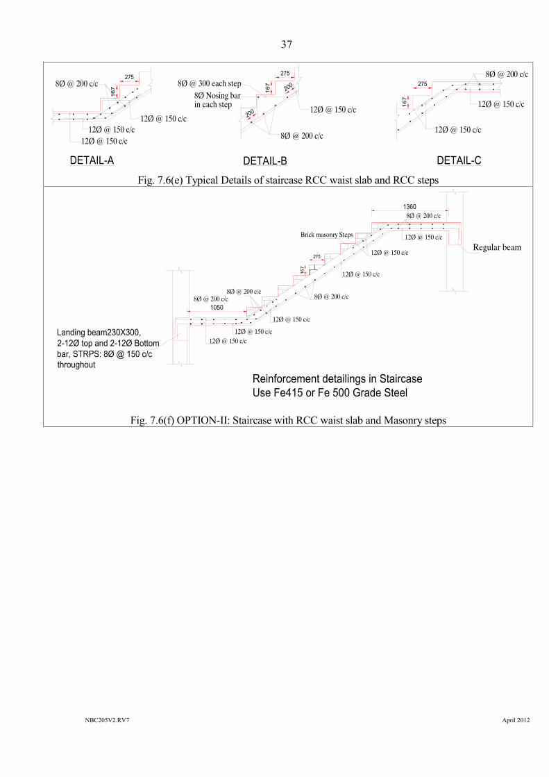
i) Staircase incline slab depth = 125 mmii) Trade and raise size : As per building planiii) Width of the staircase flight : 1050 mm
Fig. 7.6(c) Staircase Elevation
Fig. 7.6(d) OPTION-I:Staircase with RCC waist slab and RCC steps
Regular beam
Tie beam
Landing beam
Regular beam
Landing beam
Tie beam
Note: Landing beam should be supported on wall only. Do not use column near by to support this beam
Wall supporting Landing beam
Wall supporting Landing beam
To Foundation To Foundation
STO
RY
HEI
GH
T
1050
Regular beam
1360
275
Landing beam230X300,2-12Ø top and 2-12Ø Bottombar, STRPS: 8Ø @ 150 c/cthroughout
8Ø @ 200 c/c
12Ø @ 150 c/c
8Ø @ each step
12Ø @ 150 c/c
12Ø @ 150 c/c
12Ø @ 150 c/c
12Ø @ 150 c/c
12Ø @ 150 c/c
8Ø @ 200 c/c
8Ø @ 200 c/c8Ø @ 200 c/c
Reinforcement detailings in StaircaseUse Fe415 or Fe 500 Grade Steel
X-Section OF Landing Beam
230
300 8mmØ @150mmc/c
2-12Ø bars.
2-12Ø bars. B
A
167
C
Option-I: Staircase of RCC Slab and RCC Steps
37
NBC205V2.RV7 April 2012
Fig. 7.6(e) Typical Details of staircase RCC waist slab and RCC steps
Fig. 7.6(f) OPTION-II: Staircase with RCC waist slab and Masonry steps
12Ø @ 150 c/c12Ø @ 150 c/c
8Ø @ 200 c/c275
167
12Ø @ 150 c/c
8Ø @ 300 each step
DETAIL-A DETAIL-B
275
8Ø @ 200 c/c
12Ø @ 150 c/c
275
12Ø @ 150 c/c
12Ø @ 150 c/c167
8Ø @ 200 c/c
DETAIL-C
167
in each step
200
200
8Ø Nosing bar
Typical Flight Details
1050
Regular beam
1360
275
Landing beam230X300,2-12Ø top and 2-12Ø Bottombar, STRPS: 8Ø @ 150 c/cthroughout
8Ø @ 200 c/c
12Ø @ 150 c/c
12Ø @ 150 c/c
12Ø @ 150 c/c
12Ø @ 150 c/c
12Ø @ 150 c/c
12Ø @ 150 c/c
8Ø @ 200 c/c
8Ø @ 200 c/c8Ø @ 200 c/c
Reinforcement detailings in StaircaseUse Fe415 or Fe 500 Grade Steel
167
Option-II: Staircase of RCC Slab and Brick Masonry Steps
Brick masonry Steps
38
NBC205V2.RV7 April 2012
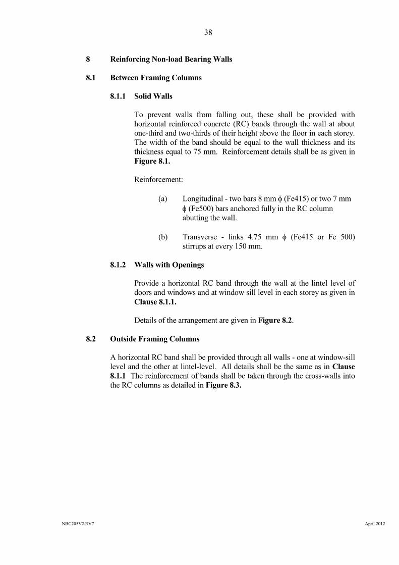
8 Reinforcing Non-load Bearing Walls
8.1 Between Framing Columns
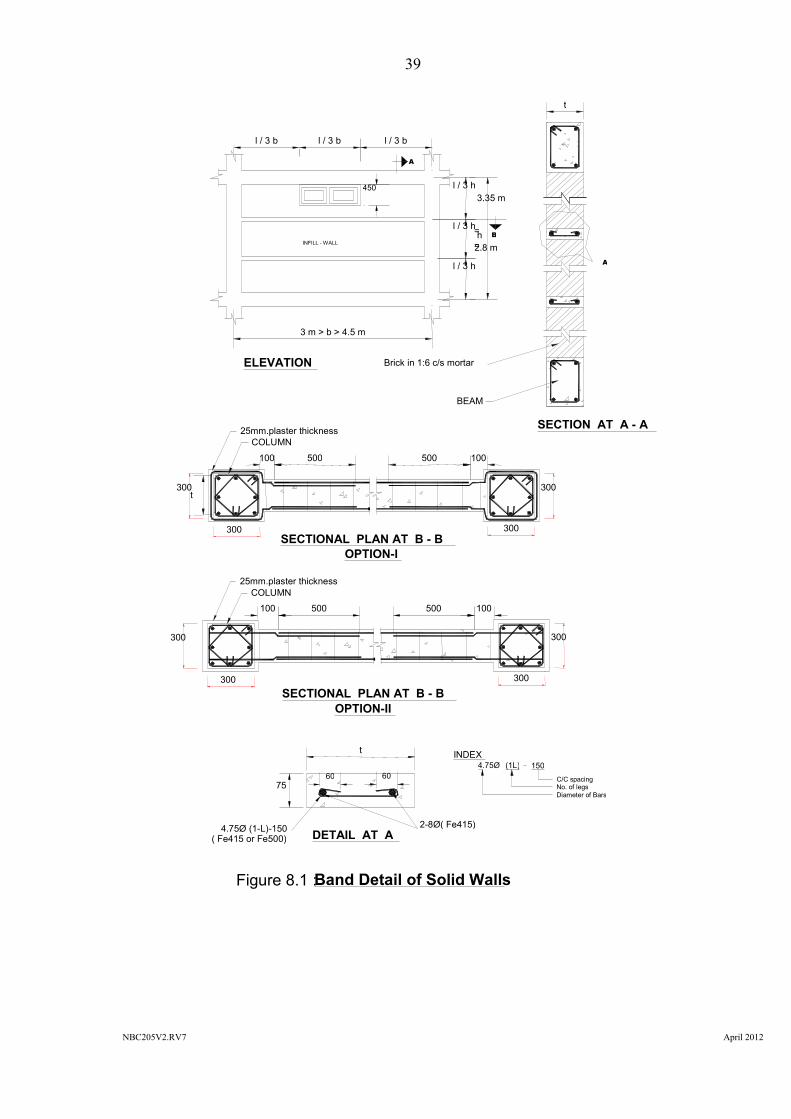
8.1.1 Solid Walls
To prevent walls from falling out, these shall be provided withhorizontal reinforced concrete (RC) bands through the wall at aboutone-third and two-thirds of their height above the floor in each storey.The width of the band should be equal to the wall thickness and itsthickness equal to 75 mm. Reinforcement details shall be as given inFigure 8.1.
Reinforcement:
(a) Longitudinal - two bars 8 mm (Fe415) or two 7 mm (Fe500) bars anchored fully in the RC columnabutting the wall.
(b) Transverse - links 4.75 mm (Fe415 or Fe 500)stirrups at every 150 mm.
8.1.2 Walls with Openings
Provide a horizontal RC band through the wall at the lintel level ofdoors and windows and at window sill level in each storey as given inClause 8.1.1.
Details of the arrangement are given in Figure 8.2.
8.2 Outside Framing Columns
A horizontal RC band shall be provided through all walls - one at window-silllevel and the other at lintel-level. All details shall be the same as in Clause8.1.1 The reinforcement of bands shall be taken through the cross-walls intothe RC columns as detailed in Figure 8.3.
39
NBC205V2.RV7 April 2012
300
300 300
300
( Fe415 or Fe500)2-8Ø( Fe415)
INDEX4.75Ø (1L) 150
C/C spacingNo. of legsDiameter of Bars
300
OPTION-I
l / 3 b l / 3 b l / 3 b
450
l / 3 h
l / 3 h
l / 3 h
2.8 m=h=
3.35 m
OPTION-IISECTIONAL PLAN AT B - B
100 500 100500
COLUMN25mm.plaster thickness
300 300
300
25mm.plaster thickness
t
3 m > b > 4.5 m
Figure 8.1 :Band Detail of Solid Walls
ELEVATION
SECTION AT A - A
SECTIONAL PLAN AT B - B
DETAIL AT A
COLUMN
100 500 100500
t
BEAM
Brick in 1:6 c/s mortar
t
7560 60
4.75Ø (1-L)-150
INFILL - WALL
A
B
A

40
NBC205V2.RV7 April 2012
BEAM
Wall below Sill level
Sill band
T12 Ø Single verticalbar through mortar
Door frame
DETAIL AT Y
450
450
Y
300
300 300
300
OPTION-I
Figure 8.2 :Band Detail of Solid Walls
SECTIONAL PLAN AT B - B
DETAIL AT X
COLUMN100 500 100500
t
7560 60
4.75Ø (1-L)-150( Fe415 or Fe500)
2-8Ø( Fe415)
INDEX4.75Ø (1L) 150
C/C spacingNo. of legsDiameter of Bars
300
300 300
300
25mm.plaster thickness
t
OPTION-IISECTIONAL PLAN AT B - B
100 500 100500
COLUMN25mm.plaster thickness
>300
2.8 m=h=
3.35 m
3 m > b > 4.5 m
ELEVATION
SECTION AT A - A
t
BEAM
X
B
A
B
A
230

41
NBC205V2.RV7 April 2012
X- SECTION OF TIE BEAM
t
75
60 60
2 T 08K 4.75 (I-L)-150
500
500
300
WALL OUTSIDE COLUMN LINE
INSIDE
OUTSIDE
WALL ABUTTING COLUMN
COLUMN
ELEVATION
LINTEL BAND
SILL BAND
SECTION AT B - B
325
500
500
DETAIL AT B
DETAIL AT A
300
DETAIL AT C
300
B
t
t
t
t
B
4.75ϕ (1-L)-150 2-8 ϕ (Fe475)
A
BC
X- SECTION OF TIE BEAM
t
75
60 60
2 T 08K 4.75 (I-L)-150
500
500
300
WALL OUTSIDE COLUMN LINE
INSIDE
OUTSIDE
WALL ABUTTING COLUMN
COLUMN
ELEVATION
LINTEL BAND
SILL BAND
SECTION AT B - B
325
500
500
DETAIL AT B
DETAIL AT A
300
DETAIL AT C
300
B
t
t
t
t
B
4.75ϕ (1-L)-150 2-8 ϕ (Fe475)

42
NBC205V2.RV7 April 2012
300
150 mm lapHalf thk Brick Wall
12.5
mm
Pla
ster
450 mm Wide GI Chickenwire mesh
Half Brick thk PartitionWall
Z1 Z1
Z2
Z2
2 mm GI Anchors @ 300 c/cStaggered at each alternatebrick course
2 mm GI Anchors @ 300 c/cStaggered at each alternatebrick course
12.5 mm Plaster
ELEVATION
SECTIONAL PLAN AT Z1 - Z1
SECTION AT Z2 - Z2
Figure 8.4 :BAND Detail of Solid Partition Walls
Mortar joint
450 mm Wide GI Chickenwire mesh

43
NBC205V2.RV7 April 2012
2.75
m=
h=
3.35
m
3 m > b > 4.5 m
ELEVATION
230
300
Half thk Brick Wall12.5
mm
Pla
ster
Horizontal band450 mm Wide GIChicken wire meshZ2
Z2
Half Brick thkWall with door
12.5
mm
Pla
ster
150 mm lap
Y
Vertical band450 mm Wide GIChicken wire mesh
Z
Vertical band450 mm Wide GI Chicken wire mesh
Vertical band450 mm Wide GIChicken wire mesh
2 mm GI Anchors@ 300 c/c Staggered at eachalternate brick course
2 mm GI Anchors@ 300 c/c Staggered ateach alternate brick course
Detail Z
RC Beam
5 Nos of 75 mm nailwith washer
Vertical band450 mm Wide GI Chickenwire mesh
100
Detail Y
Z3 Z3
230
SECTIONAL PLAN AT Z3 - Z3
Figure 8.5 :BAND Detail of Solid Partition Walls
2 mm GI Anchors @ 300 c/cStaggered at each alternatebrick course
12.5 mm Plaster
SECTION AT Z2 - Z2
Mortar joint
450 mm Wide GI Chickenwire mesh

44
NBC205V2.RV7 April 2012
9 Parapets
9.1 General
Parapets above roofs and at the edges of the balconies shall not be taller thanone metre. They should either be constructed in reinforced concrete or bereinforced with vertical RC elements spaced not more than 1.5 m apart. Thesection of the vertical RC post may be kept to b x 75 mm, where b is thethickness of the parapet. Such RC elements should be reinforced with twovertical bars of 8 mm diameter steel (grade Fe415)/7 mm Fe 500 withtransverse links 4.75 mm diameter steel (grade Fe415/Fe 500) @ 150 mmcentres. The vertical reinforcement shall be tied in the steel of the slab orbeam below with a minimum embedment of 300 mm. Also, a handrailshould be provided at the top with a section size and reinforcing as explainedin Clause 8.1.1. For details, refer to Figure 9.1.
9.2 Flower Pots
Flower pots should not normally be placed on parapets. However, if it isdesired that they be placed there, they shall be adequately wired and held tothe parapet through pre-fixed steel hooks/anchors so that they will not bedislodged in severe earthquake shaking.
HAND RAIL
SECTION AT A - A
Wal
l thi
ckne
ss
75
5050
2 T 08
K 4.75 (I-L)-150
Figure 9.1 : Parapet Wall Tie-up Details
300
300
300
A
4.75ϕ (1-L)-150
2-8 ϕ (Fe415)