Embed Size (px)
Citation preview
AD-A243 115
NAVAL 'roSTGRADUATE SCHOOLMonterey, California D T I C
S ELECTF 0DEC 7 1991
C
THESISARMY JTIDS: A C3 CASE STUDY
by
Richard E. Volz, Jr
March, 1991
Thesis Advisor: Donald A. Lacer
Approved for public release; distribution is unlimited
91-17183
91 1? 5 lID
UnclassifiedSECURITY CLASSIFICATION OF THIS PAGE
REPORT DOCUMENTATION PAGEI a- REPORT SECURITY CLASSIFICATION 1 b. RESTRICTIVE MARKINGSUNCLASSIFIED
2a. SECURITY CLASSIFICATION AUTHORITY 3. DISTRIBUTION/AVAILABILITY OF REPORT
2 Approved for public release; distribution is unlimited.2b. DECLASSIFICATION/DOWNGRADING SCHEDULE
4. PERFORMING ORGANIZATION REPORT NUMBER(S) 5. MONITORING ORGANIZATION REPORT NUMBER(S)
6a NAME OF PERFORMING ORGANIZATION 16b. OFFICE SYMBOL 7a. NAME OF MONITORING ORGANIZATIONNaval Postgraduate School (If applicable) Naval Postgraduate School
6c. ADDRESS (City, State, and ZIP Code) 7b. ADDRESS (City, State, and ZIP Code)Monterey, CA 93943-5000 Monterey, CA 93943-5000
8a. NAME OF FUNDING/SPONSORING 8b. OFFICE SYMBOL 9. PROCUREMENT INSTRUMENT IDENTIFICATION NUMBERORGANIZATION (If applicable)
8c. ADDRESS (City, State, andZIP Code) 10. SOURCE OF FUNDING NUMBERSProgram Element No. Project NO Task No. Work Unit Accesawon
Number
11. TITLE (Include Security Classification)
ARMY JTIDS: A C3 CASE STUDY, UNCLASSIFIED
12. PERSONAL AUTHOR(S) Voiz, Richard E. Jr.
13a TYPE OF REPORT 13b TIME COVERED 14. DATE OF REPORT (year, month, day) 15. PAGE COUNTMaster's Thesis From To March, 1991 142
16. SUPPLEMENTARY NOTATIONThe views expressed in this thesis are those of the author and do not reflect the official policy or position of the Department of Defense or the U.S.Government.17 COSATI CODES 18. SUBJECT TERMS (continue on reverse if necessary and identify by block number)
FIELD GROUP SUBGROUP JTIDS, Command, Control, Communications, ATCCS, JSTARS
19 ABSTRACT (continue on reverse if necessary and identify by block number)
The author examines the Army command, control, and communications aspects of the Joint TacticalInformation Distribution System (JTIDS). The developmental history of JTIDS as a secure, jam-resistant, datadistribution system is discussed with emphasis placed on the acquisition process. An overview of the system,highlighting the key components, is also presented. Particular emphasis is placed on management of thenetwork and the currentjoint concept of operations. The potential of JTIDS to pass other forms of surveillanceinformation is examined. In particular, the Joint Surveillance Target Attack Radar System (JSTARS) producesa wealth of information for all Army C2 elements. JTIDS can provide the means to transmit JSTARS groundsurveillance data to the Army Tactical Command and Control System (ATCCS), making this informationavailable to users that would not ordinarily receive it. Total Battlefield Automated System integration is thekey component for full exploitation of this information.
20 DISTRIBUTION/AVAILABILITY OF ABSTRACT 21. ABSTRACT SECURITY CLASSIFICATIONUNCLASSIFIEOUNLIMIT 3SEo AME AS REPORT 13OTIC USERS Unclassified
22a. NAME OF RESPONSIBLE INDIVIDUAL 22b. TELEPHONE (Include Area code) 22c. OFFICE SYMBOLProfessor Donald A Lacer (408) 646-2772 CC
DD FORM 1473,84 MAR 83 APR edition may be used until exhausted SECURITY CLASSIFICATION OF THIS PAGEAll other editions are obsolete Unclassified
i

Approved for public release; distribution is unlimited.
Army JTIDS: A C3 Case Study
by
Richard E. Volz, Jr.Captain, United States Army
B.S., Siena College, 1983
Submitted in partial fulfillmentof the requirements for the degree of
MASTER OF SCIENCE IN SYSTEMS TECHNOLOGY(JOINT COMMAND, CONTROL, AND COMMUNICATIONS)
from the
NAVAL POSTGRADUATE SCHOOL
March 1991
Author: all.
Richard E. Volz, Jr.(J -
Approved by: 4 C> /Donald A. Lacer, Thesis Advisor,
Michael G. Sovereign, Second Redder
Carl R Jgnes, Cl~rman
Joint Command, Control, an unications Academic Group
ii
ABSTRACT
The author examines Army command, control, and
communications aspects of the Joint Tactical Information
Distribution System (JTIDS). The developmental history of
JTIDS as a secure, jam-resistant, data distribution system is
discussed with emphasis placed on the acquisition process. An
overview of the system, highlighting the key components, is
also presented. Particular emphasis is placed on management
of the network and the current joint concept of operations.
The potential of JTIDS to pass other forms of surveillance
information is examined. In particular, the Joint
Surveillance Target Attack Radar System (JSTARS) produces a
wealth of information for all Army C2 elements. JTIDS can
provide the means to transmit JSTARS ground surveillance data
to the Army Tactical Command and Control System (ATCCS),
making this information available to users that would not
ordinarily receive it. Total Battlefield Automated System
integration is the key component to full exploitation of this
information.
MC TAhbAe o'g .d Lio
T~1 psd/S_Di st b . /
TABIZ OF CONTENTS
CHAPTER I. HISTORICAL EVOLUTION ............ 1
A. INTRODUCTION ......... ................. 1
1. Purpose .......... .................. 1
2. Definition ......... ................. 1
3. Scope ........... ................... 1
4. Background ......... ................. 2
5. Joint Concept of Operations .... ........ 5
B. PROGRAM HISTORY ....... .. ................ 6
1. Phase Development ....... ............. 6
a. Phase I ...... ... ................ 7
b. Phase II ....... .. ................ 9
2. Congressional Review ... ............ 10
3. Multifunctional Information Distribution
System (MIDS) ..... ............... 11
C. SYSTEM EVALUATION ...... ............... 13
1. Technology Risk ..... .............. 13
2. Program Cost ...... ................ 15
3. Schedule/Milestones .... ............ 18
4. JTIDS and NATO ...... ............... 20
5,.,Test and Evaluation .... ............ 21
CHAPTER II. SYSTEM OVERVIEW ..... .............. 25
iv
A. SYSTEM'DESCRIPTION ..... .............. 25
B. SYSTEM TECHNOLOGY ...... ............... 26
C. MESSAGE STRUCTURE ...... ............... 29
D. INFORMATION DISTRIBUTION ... ........... 31
E. RELAY FUNCTION ...... ................ 33
1. Paired Slot Relay .... ............. 33
2. Repromulgation Relay .... ............ 34
F. ACCESS MODES ......... ................. 34
1. Dedicated Access ..... .............. 34
2. Contention Access .... ............. 35
3. Distributed Reservation Access ........ .. 35
G. VOICE ......... ..................... 36
H. POSITION LOCATION ...... ............... 37
I. IDENTIFICATION ...... ................ 38
J. CLASSES OF TERMINALS .... ............. 38
1. Class 1 Terminal ..... .............. 39
2. Class 2 Full Scale Development Terminal . 39
3. Class 2M Terminal .... ............. 41
4. Class 2H Terminal ............. 43
5. Class LV Terminal ............. 43
CHAPTER III. NETWORK MANAGEMENT .... ............ 46
A. DEFINITION ....... .................. 46
B. NETWORK MANAGEMENT OVERVIEW ... .......... 46
1. Class 1 Terminal Network ... .......... 47
2. Class 1 and 2 Terminal Networks . ...... 51
v
C. NETWORK DESIGN FOR JTIDS JTAO .. ......... . 58
D. ARMY NET MANAGEMENT .... .............. .. 60
1. Means of Employment ... ............ 60
2. Army JTIDS Network Employment . ....... .. 63
CHAPTER IV. CONCEPT OF OPERATIONS ... ........... . 66
A. JCS JOINT CONCEPT OF OPERATIONS .. ........ .. 66
1. Current Joint Tactical Air Operations . . 66
2. Information Exchange (Non-JTIDS) ....... . 69
a. Track and Track Management ........ .. 70
b. C2 Unit Status .... ............. .. 71
c. C2 Coordination ... ............ 71
d. Special Information Transfer ....... .. 72
e. Summary ..... ................ 73
3. JTIDS Equipped Joint Tactical Air Operations 73
a. Position and Status Reporting ..... 78
b. Surveillance .... .............. .. 78
c. Target Selection and Coordination . . 79
d. Navigation ..... ............... .. 79
e. Digital Voice .... ............. .. 79
B. ARMY CONCEPT OF OPERATIONS .. .......... . 80
1. Introduction ..... ................ .. 80
2. Airland Battle Doctrine .. .......... . 80
3. Army Command and Control Systems ....... .. 82
4. Three Pillared Architecture . ........ . 83
a. Area Common User System . ........ .. 84
vi
b. Combat Net Radio .... ............ 85
c. Army Data Distribution System ..... 86
5. Army JTIDS/EPLRS Employment .. ........ 88
CHAPTER V. PROPOSED APPLICATIONS FOR JTIDS INFORMATION
DISTRIBUTION ........ ................... 91
A. INTRODUCTION ...... ................. 91
B. AIRLAND BATTLE - FUTURE .... ............ 91
1. Projected Doctrine .... ............. 91
2. Communications Support ... ........... 94
C. JTIDS - A VITAL LINK FOR ALB-F . ........ 95
1. Joint Surveillance Target Attack Radar
System ....... ................... 95
2. JTIDS - A Gateway to the Sigma Star . . .. 98
D. A PROPOSED JTIDS ALTERNATIVE ... .......... 99
1. Maneuver Control ..... ............. 101
2. Air Defense Artillery ... ........... 103
3. Fire Support ...... ................ 104
4. Intelligence/Electronic Warfare . ...... 105
5. Combat Service Support ... ........... . 106
E. HURDLES TO OVERCOME . .... .............. 109
1. Data Fusion ...... ................ 109
2. Decision Support Algorithms .. ........ 110
3. Multilevel Security ..... ............ 111
4. Doctrine ....... .................. 112
5. Summary ....... .................. 114
vii
CHAPTER VI. CONCLUSIONS AND RECOMMENDATIONS ..... 115
A. SUMMARY ........ .................... 115
B. CONCLUSIONS ....... .................. 115
C. RECOMMENDATIONS ...... ................ 116
1. Timely Fielding ..... .............. 116
2. Continued JTIDS Development .. ........ 116
3. NCS-J - The Joint Management Tool ..... 117
4. JTIDS Transmission of JSTARS Information 117
LIST OF REFERENCES ....... .................. 119
INITIAL DISTRIBUTION LIST ...... ............... 123
viii
LIST OF TABLES
TABLE 1 System Requirements for Each Phase ... ...... 8
TABLE 2 JTIDS Family of Terminals .. .......... 12
TABLE 3 Projected JTIDS Program Development Costs 18
TABLE 4 Projected Milestones .... ............. 20
TABLE 5 JTIDS Class 2 Cost Estimates as of February
1990 ......... ..................... 24
TABLE 6 JTIDS Operational Requirements ......... 25
TABLE 7 JTIDS Terminal Capabilities .. ......... 45
ix
LIST OF FIGURES
Figure 1 Planned JTIDS Users ....... ............. 7
Figure 2 JTIDS System Technology ... ........... . 11
Figure 3 JTIDS Signal Structure ... ........... . 26
Figure 4 JTIDS Time Slot rtructures .. ......... . 28
Figure 5 IJMS Message Structure ... ........... . 31
Figure 6 TADIL J Message Structure ... .......... . 32
Figure 7 JTIDS Voice ...... ................. .. 37
Figure 8 JTIDS Multi-Purpose Color Display ....... .. 42
Figure 9 JTIDS Single Net Operations .. ......... . 48
Figure 10 JTIDS Multinet Operations .. ......... . 54
Figure 11 Terminal Initialization Load Generation . 57
Figure 12 Army JTIDS Communication System ...... .. 62
Figure 13 Division JTIDS Network Management ..... 65
Figure 14 Current Joint Air Operations .. ........ .. 67
Figure 15 JTIDS Concept of Operations . ........ .. 75
Figure 16 The Army Command and Control System . . .. 83
Figure 17 The Three Pillared Communication
Architecture ..... ................ .. 84
Figure 18 Deployment of Army Communication Systems 88
Figure 19 The PLRS/JTIDS Hybrid System .. ........ .. 89
Figure 20 Airland Battle - Future Concept ...... .. 93
Figure 21 Communications on the Non-Linear Battlefield 96
Figure 22 The JSTARS Radar Platform .. ......... . 98
x

Figure 23 The JTIDS Alternative ... ........... 100
Figure 24 Integrated Information Flow .. ........ 108
Figure 25 Potential ATCCS Management .. ......... 113
xi
TABLE OF ABBREVIATIONS
ABMOC Air Battle Management Operations Center
ACCS Army Command and Control System
ACUS Area Common User System
ADA Air Defense Artillery
ADDS Army Data Distribution System
ADSO Assistant Division Signal Officer
AFATDS Advanced Field Artillery Tactical Data
System
AFP Assault Fire Platoon
ALB Airland Battle
ALB-F Airland Battle-Future
ASAS All Source Analysis System
ASIT Adaptable Surface Interface Terminal
ATCCS Army Tactical Command and Control System
ATDL-l Army Tactical Data Link-i
AWACS Airborne Warning And Control System
BAS Battlefield Automated System
BDEFDC Brigade Fire Direction Center
BIT Built-in-Test
BFA Battlefield Functional Area
BNFDC Battalion Fire Direction Center
CAC Combined Arms Center
C2 Command and Control
CCSK Cyclic Code Shift Keying
xii
CIP Communication Improvement Program
CNR Combat Net Radio
CONOPS Concept of Operations
CONUS Continental United States
CPSM Continuous Phase Shift Modulation
CRC Control and Reporting Center
CRP Control and Reporting Post
CSS Combat Service Support
CSSCS Combat Service Support Control System
CVSD Continuous Variable Slope Delta
DAB Defense Acquisition Board
DCA Defensive Counterair
DJRU Dedicated JTIDS Relay Unit
DME Distance Measuring Equipment
DTDMA Distributed Time Division Multiple Access
DTI Data Transfer Module
EAC Echelons Above Corps
ECM Electronic Counter Measures
EPLRS Enhanced Position Reporting Location
System
EPUU EPLRS User Unit
EW Electronic Warfare
FAAD Forward Area Air Defense
FACP Forward Area Control Post
FAADC2I FAAD Command, Control, and Intelligence
FM Field Manual
xiii
FS Fire Support
FSD Full Scale Development
GAO Government Accounting Office
GSM Ground Station Module
HF High Frequency
HIC High Intensity Conflict
HIMAD High to Medium Air Defense
HIU Host Interface Unit
ICP Interface Control Panel
IEW Intelligence/Electronic Warfare
IHFR Improved High Frequency Radio
IJMS Interim JTIDS Message Specification
ITNS Integrated Tactical Navigation System
JCS Joint Chiefs of Staff
JINTACCS Joint Interoperability Program for
Tactical Command and Control Systems
JMSWG JTIDS Message Standards Working Group
JOPM JTIDS Operational Performance Model
JOR Joint Operating Requirement
JPO Joint Program Office
JSTARS Joint Surveillance Target Attack Radar
System
JTAO Joint Tactical Air Operations
JTIDS Joint Tactical Information Distribution
System
Kbs Kilobits per Second
xiv

LIC Low Intensity Conflict
LNO Liaison Officer
LRIP Low Rate Initial Production
MCS Maneuver Control System
MIC Medium Intensity Conflict
MIDS Multinational Information Distribution
System
MLS Multilevel Security
MPC Message Processing Center
MPCD Multi-Purpose Color Display
MSE Mobile Subscriber Equipment
MSRT Mobile Subscriber Radio Telephone
NATO North Atlantic Treaty Organization
NCS Net Control Station
NCS-J Net Control Station-JTIDS
O&C Operations and Control
OSD Office of the Secretary Of Defense
PCDP Pilot Control and Display Panel
PJHI PLRS-JTIDS Hybrid Interface
PLRS Position Location Reporting System
PPLI Precise Position Location Identification
PT Enhanced PLRS Terminal
RATT Radio Teletype
RL Rapid Load
RSC Radio Set Control
SACP Stand Alone Control Panel
xv
SAM Surface to Air Missile
SDS Software Development Station
SINCGARS Single Channel Ground and Airborne Radio
System
SYSCON System Control
TACAN Tactical Air Navigation
TACS Tactical Air Control System
TADIL Tactical Data Information Link
TADIL J Tactical Data Information Link JTIDS
TCT Tactical Computer Terminal
TDMA Time Division Multiple Access
TRADOC Training and Doctrine Command
TRI-TAC Tri-service Tactical Communications
URO User Readout
WAN Wide Area Network
xvi

ACKNOWLZDGMZNTS
The author wishes to express his appreciation to Colonel
William Guerra, Director of Combat Developments, United States
Army Signal Center, Fort Gordon for his sponsorship.
Professor Donald A. Lacer and Professor Michael G. Sovereign
provided invaluable support and advise throughout the
development of this thesis. Special thanks are provided to
Captain James Kohlman, Captain David S. Velasquez, and Captain
David J. Sacha for their invaluable assistance in researching
this thesis.
xvii
CHAPTER I. HISTORICAL EVOLUTION
A. INTRODUCTION
1. Purpose
This chapter presents an introduction to the Joint
Tactical Information Distribution System (JTIDS). It will
examine JTIDS's mission requirements and its history of
development to meet those needs. The system's procurement
history and current procurement status will be discussed.
2. Definition
JTIDS is a secure, jam-resistent data and voice
communications system. The system enables the exchange of
real-time tactical information between joint forces concerning
friend and foe alike. The information exchange includes force
identification, location, and command and control data. [Ref.
l:p 11]
3. Scope
This thesis will present JTIDS under its command and
control aspects. An examination of JTIDS potential
applications for information distribution on future
battlefields will also be performed. Chapter I examins the
history of JTIDS development as a data distribution system for
joint air operations. Chapter II presents an overview of
JTIDS and highlights key components in the system. The
1
components will include the major terminals and their
interfaces with various platforms. Chapter III reviews
current concepts to plan and manage a JTIDS network. Chapter
IV discusses the current Joint CONOPS for JTIDS employment.
The communication architecture planned by the U.S. Army will
also be presented. Chapter V presents potential JTIDS
interfaces into the ATCCS. A number of proposals are
developed for use of JTIDS provided information. Primary
among the information sources is the U.S. Air Force JSTARS
ground surveillance aircraft. The last portion of the chapter
is devoted to the problems inherent in the integration of
automation devices on the battlefield.
4. Background
The war in Vietnam, particularly the air war,
demonstrated U.S. forces' inability to effectively employ
combat power. Much of this ineffectiveness was due to
inadequate command and control (C2) capabilities. Aircraft
and weapon systems have dramatically increased both their
capabilities and lethality, while C2 has lagged behind. The
air war over North Vietnam is a case in point. [Ref. 2:p 25]
In 1972 the U.S. was withdrawing it's land forces from
the Asian land mass. The North Vietnamese viewed this as an
opportunity to capture South Vietnam with limited U.S.
opposition. It was decided by then-President Richard Nixon to
commit U.S. air power over North Vietnam to stem the flow of
2
arms to the South. The ensuing air war over North Vietnam
clearly displayed our command and control weaknesses.
North Vietnam was divided into geographical areas of
responsibility that were under the control of only one
service, namely the Navy or Air Force. This was done to
eliminate confusion due to incompatible C2 systems. Each
service had its own surveillance capability and intelligence
reports. Lack of interoperability of the command and control
systems prevented information sharing and all source
information processing. Invaluable information was not
shared, though both services could have benefitted from it.
In addition, aircraft from different services could not
communicate with each other. Frequencies, call signs and
radio procedures differed for each service. Navigation and
position reporting were also extremely difficult and differed
between the services. Hanoi was often used as a central
reference point. Each pilot had to be aware of his location
with reference to Hanoi. Any hostile aircraft detected were
referenced in the same manner. In a combat situation, the
pilots often became confused and misoriented. It became clear
that some form of data distribution system would be required
to fuse this data. The requirement to share information
throughout the theater of operation, as a joint network was
self-evident. [Ref. 2:p 13]
The 1973 Mideast War between Israel and Egypt pointed
out, in a rather dramatic manner, a major weakness in U.S.
3
communication systems. Israeli intelligence reported that
Egyptian forces used Soviet-developed jammers during the
conflict that virtually blocked all inter-aircraft
communications. This threat was viewed in it's implications
for a land war in Central Europe, and a need for jam-resistent
communications was given a greater priority. [Ref. 3:p 25]
In 1974, the Joint Chiefs of Staff issued a service-
wide directive that outlined the potential threat to U.S.
forces. It also directed that a new command and control
system be developed. This system was to be jam resistant with
a method for the distribution of shared data to all
participants. [Ref. 4:p 3]
The Air Force and Navy were both directly affected by
the JCS directive. Fortunately, both had previously begun
development of tactical information distribution systems. The
Navy was developing the Integrated Tactical Navigation System
(ITNS) that was a distributed form of Time Division Multiple
Access (DTDMA). The Air Force was concurrently working on a
position, location, reporting and control system, known as
PLRACTA. This system later evolved into the SEEK BUS system.
The SEEK BUS placed it's emphasis on incorporating many
subscribers into a single network. Both developmental efforts
were pursued in order to evaluate technical requirements and
potential concepts of operation.
The Office of the Secretary of Defense (OSD) combined
both efforts in 1974 by selecting the Air Force as the lead
4
service. DTDMA and TDMA technologies were each viewed as
having potential. The Navy was to continue its efforts under
DTDMA technology with new requirements for security and jam-
resistance. Their system was designed for use over existing
Tactical Data Information Links (TADIL) links. The Air Force
continued its development of the already proven potential of
TDMA. [Ref. 4:p 3]
In 1976, a Joint Operating Requirement (JOR) was
published. It further outlined the development of a secure,
anti-jam, digital data distribution system. It also separated
further development into two phases, with different
requirements. The phases, as determined by the Under
Secretary of Defense for Research and Engineering, differed
under the criteria of system capacity, multiple netting, and
the number of voice channels per net. [Ref. 4:p 4]
5. Joint Concept of Operations
Joint operations are the norm today rather than the
exception. An integrated data distribution system is vital to
command and control of air, ground, and sea assets in the
Airland Battle. The JTIDS system incorporates all air and
ground sensor information into a coherent picture that can
then be filtered to meet unique user requirements.
Sensors, such as the Air Force E-3A AWACS and the Navy
E-2C Hawkeye,. with other air and ground sensors, can create an
integrated air picture. This snapshot of the air battle is
5
sent to all the net participants in near real-time. One of
the primary recipients is the Air Force Control and Reporting
Center (CRC). The CRC is responsible for the conduct of air
defense and air space control over the area designated by the
Joint Force Commander. The CRC will perform a management
function over subordinate Control and Reporting Posts (CRPs)
and U.S. and NATO E-3As. When Army surface-to-air missiles
(SAMs) are assigned to operate in a joint air defense
environment, the CRC provides operational control over the SAM
employment. The CRC establishes an air picture of its area of
responsibility. This is accomplished through local radar and
the cross telling of track information among all the elements
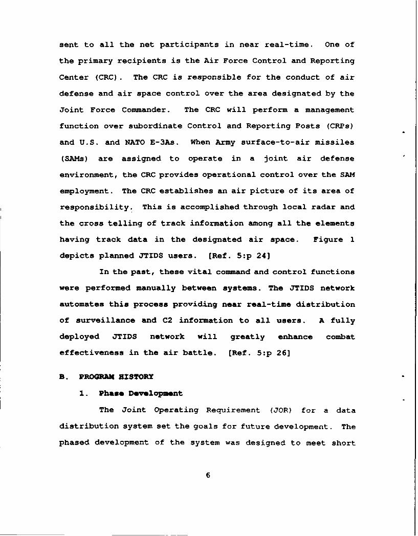
having track data in the designated air space. Figure 1
depicts planned JTIDS users. [Ref. 5:p 24]
In the past, these vital command and control functions
were performed manually between systems. The JTIDS network
automates this process providing near real-time distribution
of surveillance and C2 information to all users. A fully
deployed JTIDS network will greatly enhance combat
effectiveness in the air battle. [Ref. 5:p 26]
B. PROGRAM HISTORX
1. Phase Development
The Joint Operating Requirement (JOR) for a data
distribution system set the goals for future development. The
phased development of the system was designed to meet short
6

US N AVYYUV
US E-3A AC _
US NAVY CV U N'D-
USAF CRC
' . , US ARMY
USAF "TSO-?3MPC . -. ASIT USMCIUSAF
TAOC-IIMCE
Figure 1 Planned JTIDS Users
and long term goals. Phase I established minimum essential
requirements to meet the Air Force's desperate need for a data
link between the E-3A AWACS and ground C2 centers. Phase II
-was to produce a terminal with a greatly enhanced data
capacity and netting capability. Table 1 depicts the specific
digital requirements for each phase.
a. Phase I
The first priority for the Air Force was to develop
a data distribution terminal for the E-3A AWACS and NATO E-
3As. The Hughes Aircraft CO., under a $20 million contract,
7
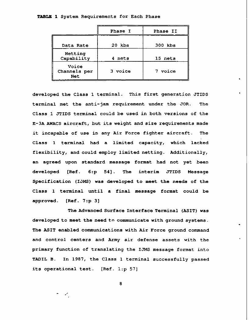
TABLI 1 System Requirements for Each Phase
I - Phase I Phase II
Data Rate 20 kbs 300 kbs
NettingCapability 4 nets 15 nets
VoiceChannels per 3 voice 7 voice
Net 1_ _ _
developed the Class 1 terminal. This first generation JTIDS
terminal met the anti-jam requirement under the JOR. The
Class 1 JTIDS terminal could be used in both versions of the
E-3A AWACS aircraft, but its weight and size requirements made
it incapable of use in any Air Force fighter aircraft. The
Class 1 terminal had a limited capacity, which lacked
flexibility, and could employ limited netting. Additionally,
an agreed upon standard message format had not yet been
developed [Ref. 6:p 54]. The interim JTIDS Message
Specification (IOMS) was developed to meet the needs of the
Class 1 terminal until a final message format could be
approved. [Ref. 7:p 3]
The Advanced Surface Interface Terminal (ASIT) was
developed to meet the need to communicate with ground systems.
The ASIT enabled communications with Air Force ground command
and control centers and Army air defense assets with the
primary function of translating the IJMS message format into
TADIL B. In 1987, the Class 1 terminal successfully passed
its operational test. [Ref. l:p 57]
8
b. Phase II
The development of the first generation JTIDS
terminal (Class 1) established the operational capability of
the TDMA technology. The Class 1 terminal was too large and
heavy and had limited capabilities to be used in tactical
aircraft. Phase II development began well before Phase I
requirements were met. It focused on reduction in terminal
size, weight, and greatly enhanced data capability. The Air
Force and Army continued with development of TDMA technology.
The Navy was allowed to continue development of DTDMA
technology providing it was compatible with the Air Force
program. With the understanding that TADIL J was to be the
joint message format standard, both technologies were funded
for Full Scale Development (FSD)in 1981. [Ref. 8:p 7]
The Class 2 terminal was developed through TDMA
technological advances. The terminal developed was smaller,
had a much greater data capability, and an improved capacity
for netting; however, it also had its share of problems. The
Class 2 terminal was still too large to fit into smaller
tactical aircraft such as the Air Force F-16. The Army had
difficulty interfacing the Class 2 terminal with its Position,
Location, and Reporting System (PLRS). A single type of
terminal would not be able to perform all the assigned
missions; therefore, several different versions were developed
9
to meet specific requirements of individual services. [Ref.
l:p 87]
One version was the Army's Class 2M terminal. This
terminal was designed to meet the needs of the Army Air
Defense community. The Class 2M terminal differed in that it
had a data-only capability. Voice capability was determined
to be unnecessary and its elimination would reduce the
terminal's size. The Army opted for the trade-off of
capability for size. [Ref 9:p 7]
A high power version of the Class 2 terminal, the
2H is under development to meet a system requirement for
greater range. This new requirement was established to meet
the needs of:
e The Marine Corps Tactical Air Operations Module.
e Air Force Modular Control Equipment.
o Navy E-2C surveillance aircraft.
* Class 1 terminal upgrades for E-3A AWACS. [Ref. 4:p 19]
2. Congressional Review
The JTIDS program came under Congressional review in
August of 1985. A joint meeting of both the Senate and House
Armed Services Committees directed then-Secretary of Defense
Casper Weinberger to select one system that would meet the
needs of all services. The evaluation by OSD determined that
the Naval development of DTDMA technology was yielding a
product that was too complex and required costly unique micro-
10
circuitry. The Secretary of the Navy, John Lehman, canceled
all DTDMA development in October 1985. He directed that all
future naval fighters were to use the Class 2 terminals.
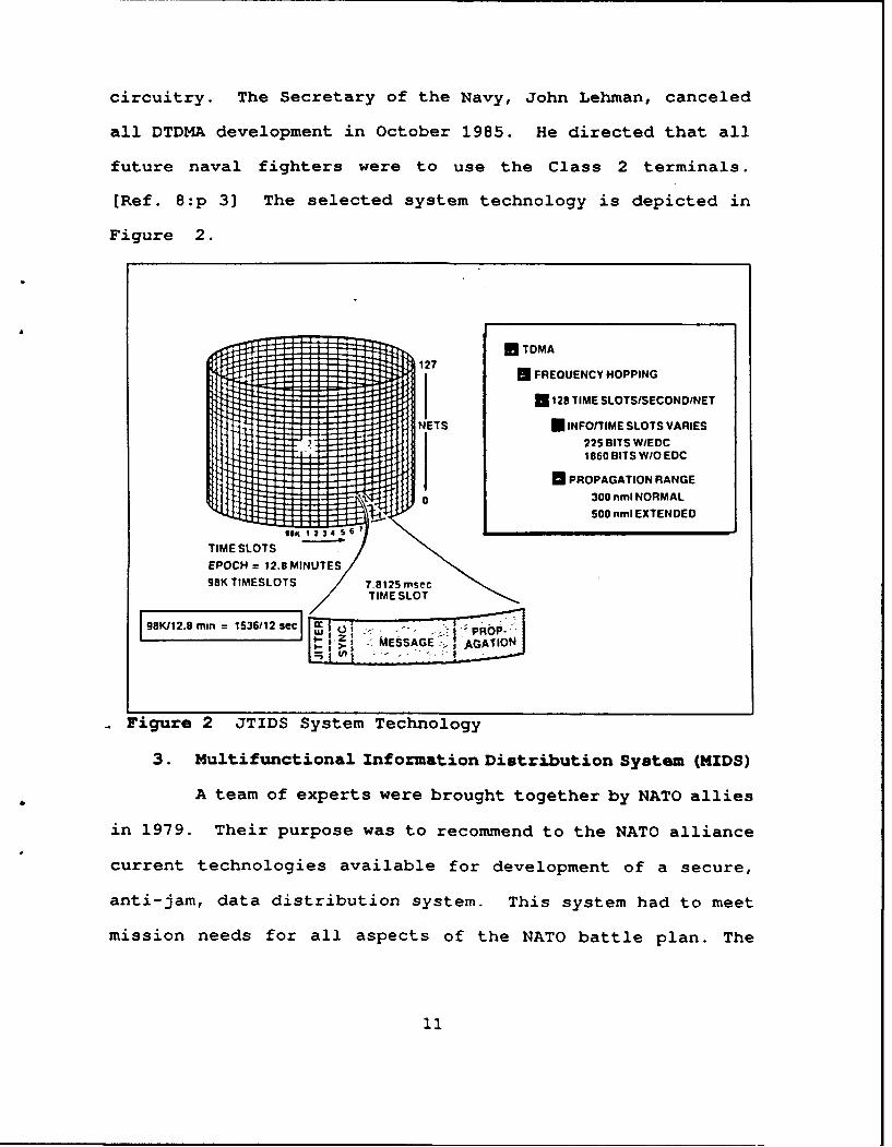
[Ref. 8:p 3] The selected system technology is depicted in
Figure 2.
U TDMA127
* FREQUENCY HOPPING
*128 TIME SLOTSISECOND/NET
NETS INFO/TIME SLOTS VARIES
225 BITS WIEDC1860 BITS W/O EDC
[ PROPAGATION RANGE- -300 nml NORMAL
500 nml EXTENDED28lK 1 23 4 $
TIME SLOTS S
EPOCH = 12.8 MINUTE98K TIMESLOTS 7.8125 msec
TIME SLOT9K812.8 rmin = 153612sec [P:R
- Figure 2 JTIDS System Technology
3. Multifunctional Information Distribution System (MIDS)
A team of experts were brought together by NATO allies
in 1979. Their purpose was to recommend to the NATO alliance
current technologies available for development of a secure,
anti-jam, data distribution system. This system had to meet
mission needs for all aspects of the NATO battle plan. The
11
team recommended that TDMA technology developed under the
JTIDS program had the greatest potential to meet those mission
needs; hence the MIDS program was established.
The MIDS program is currently in the concept
development phase. U.S. services are working concurrently
with their NATO counterparts to develop JTIDS-type terminals
that would be adaptable to a variety of NATO aircraft. The Air
Force hopes to develop a terminal that will fit into the
cockpit of their smaller tactical aircraft (i.e., F-16 and F-
18). The Navy as the lead service represents the United
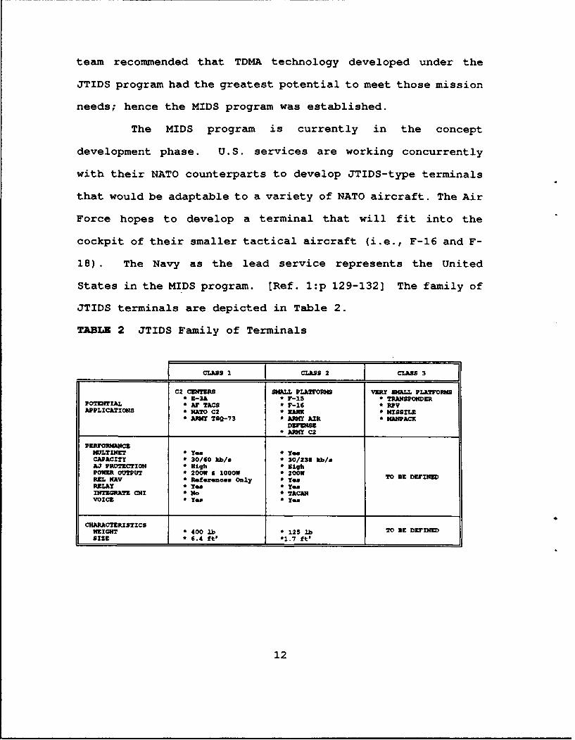
States in the MIDS program. [Ref. 1:p 129-132] The family of
JTIDS terminals are depicted in Table 2.
TABLZ 2 JTIDS Family of Terminals
CLASS I CLASS 2 CLABS 3
C2 CITERB SMALL PLATMORMS VERY SMALL PLATFORM* E-3A * F-15 * TRANSPONDER
POTENTIAL * AF TACO * r-16 * RPVAPPLICATIONS * NATO C2 * EALK * MISSILE
* AMY TSQ-73 * AR4Y AIR 'HANPACKDEFENSE
* AMY C2
PERFONWLCEMWLTINET *O * TeCAPACITY * 30/60 kb/ * 30/23S kbeAJ PROTECTION * igh * HighPOWER OUTPUT * 20OW 1000 W * 200WREL NAV * Referenae Only * yes TO BE DErINZDRELAY *Ye * YesINTEGRATE CHI * No * TACANVOICE * e *
CHARACTERISTICSWEIGHT * 400 lb * 125 lb TO 9E DEFINEDSIZE * 6.4 ft' *1.7 ft'
12
C. SYSTEM EVALUATION
1. Technology Risk
The development of a JTIDS system to meet the mission
requirements for a secure, anti-jam, data distribution system
made large assumptions about available and potential
technologies. A comprehensive assessment of the risks to the
program with a common baseline for the level of technology was
never performed. The technological risk was compounded due to
the number of new technologies required to implement the JTIDS
program.
The need for a data distribution system was the
driving force behind JTIDS development. In the early stages
of the program, the Air Force and Navy had developed two
different technologies to meet the data distribution
requirement. The Air Force was developing TDMA and the Navy
was developing DTDMA. The development of these two
technologies created two levels of risk for the program. There
was a great deal of duplication in the research and
development involved with the two approaches. Congressional
review of the program resulted in the cancellation of DTDMA
development. Naval development of DTDMA only lasted as long
as it did because of the potential savings in the long term
goal of using existing TADIL B links. [Ref. 10:p 36]
The JCS requirement for an anti-jam capability added
technical risk to the program. In 1974 this technology was in
13

its infancy. Two methods under development to overcome
potential Soviet jamming were frequency hopping and spread
spectrum technology. Frequency hopping involves signal
transmission on a randomly selected frequency within a
predetermined frequency band. Spread spectrum technology
entails spreading the message signal over a broad frequency
band. This would ensure that enough of the message signal is
received at the receiver to be accurately reproduced.
Additionally, both anti-jamming technologies added greater
risk to the program. The frequency hopping technique was
selected for incorporation into the Class 1 and Class 2
terminals. [Ref. 5:p 44]
The final technical risk is one that was never
adequately assessed. Software development for the JTIDS
terminals has continually lagged behind hardware. Over one
million lines of code have been written for eight versions of
the terminal. A standard message format for the system was
still undecided during initial testing of the Class 1
terminal. The Air Force directed the development of an
interim message format known as Interim JTIDS Message
Specification (IJMS). This format evolved in order to
continue development of the JTIDS system. IJMS was incapable
of directly interfacing with existing service command and
control centers that currently use TADIL B data links (i.e.
Air Force CRCs and MPCs). The development of the Adaptable
Surface Interface Terminal (ASIT) was driven by the IJMS,
14
enabling ground users to translate message formats. [Ref. l:p
21]
The TADIL J message format was developed by the JTIDS
Message Standards Working Group (JMSWG) of the Joint
Interoperability Program for Tactical Command and Control
Systems (JINTACCS). This message format has been accepted by
each service for employment in the JTIDS systems. The TADIL
J format was employed in all JTIDS terminals in the late
1980s. JTIDS message formats will be described in detail in
Chapter II. (Ref 7:p 6]
2. Program Cost
Program cost estimates have continually risen since
JTIDS's conceptional development. Initial life cycle cost
estimates in 1974 varied between $3 billion and $4 billion to
meet data distribution needs for the U.S. in NATO. The Joint
Program Office (JPO) increased this estimate in 1979 to $7
billion. This new life cycle cost estimate had defects. The
JPO did not perform a separate cost estimate based upon the
entire joint program; rather, it totalled all the services'
individual cost estimates to determine the joint program
figure. Further investigation reveals that the Air Force
based their estimate on current and anticipated TDMA
technology. The Air Force also included a cost escalation
factor to account for anticipated inflation rates. The Navy
based it's cost estimate on DTDMA technology under their
15
development. Naval program managers also didn't include an
inflation factor, basing their estimate solely on 1978
dollars. The Army's estimate was based on fielding the Class
2 terminal with their PLRS system in command posts only. This
estimate did not include any figure for advanced third
generation terminals to be employed with ground units. It is
also important to note here that as of 1979 the Army still
lacked approval of a mission need for JTIDS within their
service. [Ref 8:p 7]
No common baseline upon which to determine system
costs was established. In 1979, the JTIDS program was joint
in name only. Each service was maintaining its own program and
cost estimates were based on vastly different sets of
criteria. Thus, there was no basis for an accurate estimate
of the cost of the program from cradle to grave. Current
estimates call for the procurement of 1700 terminals through
the year 1997. The cost of production of these terminals is
approximately $1.7 billion. [Ref. 8:p 5]
The lead-follow contract method was employed in low
rate initial production of the Class 2 terminal. It was hoped
that this method of contracting would enhance competition and
help drive down unit cost. The lead contractor for Air Force
procurement of the Class 2 terminal is Plessey Electronics
System Corporation. The Plessey Corporation was awarded a
LR:P contract worth $90 million dollars for 47 Class 2
terminals. The first 20 terminals were designated for
16
installation in Air Force F-15 tactical fighters. The
additional 27 Class 2 terminals will be installed into Navy F-
14s and several command and control vessels. The follow
contract for low rate initial production was awarded to
Rockwell Collins, Inc. at $42 million dollars. The Class 2
terminals produced under this contract will be installed
solely on Air Force F-15s. [Ref. 9:p 10]
Current cost figures for each Class 2 terminal is
approximately $800,000 to $1 million. This estimate includes
the cost of production and initial logistical support.
Contractors, in conjunction with the JPO estimate the per unit
cost could possibly be reduced by as much as one half. A cost
reduction to $400,000 per terminal could be achieved through
experience gained on the production line and competition
between Plessey and Rockwell Collins. The cost of investment
in test equipment and tooling may be recouped by the
contractor by 1992. Unit cost reductions should then follow.
The JPO has a number of product improvement programs to aid in
life cycle cost reduction. These are as follows:
1. State of the art off-the-shelf mini processors.
2. Increase reliability of the system.
3. Bulk purchase of replacement parts.
In summary, the original developmental estimate of $3
to $4 billion was highly optimistic. Software development was
not estimated nor was the cost of having to develop two
message formats included. JTIDS software development
17

dramatically contributed to the already exceeded developmental
cost, currently over $2 billion. [Ref. 3:p 47] Recent budget
information is found in Table 3.
TABLZ 3 Projected JTIDS Program Development Costs
BUDGTPam TOT
(000) ry 1988 ry 1989 ry 1990 ry 1991 ry 1992 (TOI I I II I OWL)
MAJOR 78,603 61,120 87,130 87,806 72,317 TBDCONTRACT j _ _ _ _ _ _ _ _ _ _ _ _
3. Schedule/Milestones
Program managers are required to submit an acquisition
strategy within ninety days of appointment in accordance with
the Defense Management Review. This was never done for JTIDS
acquisition. The Air Force, as the lead service, established
few milestones, which were regularly pushed back due to a lack
of results in technological development.
Forces outside the JPO also contributed to delays in
the developmental process. The Class 1 terminal experienced
delays for several reasons. Congressional review of the JTIDS
program discovered the services were developing systems that
were not frequency compatible nor did they incorporate TACAN
frequencies. Congress then mandated that the JTIDS system
must be interoperable and TACAN frequency compatible before
further development. Additionally, the developmental phase
was extended two years, based on the Hughes Aircraft Co.'s
recommendation that added development time would enable them
18
to substantially reduce unit cost of first generation
terminals. [Ref. 8:p 5]
Development of the Class 2 terminal also suffered from
delays. Singer Kearfott and Rockwell Collins had developed
newer micro computer chips that would process data at a much
higher rate. Incorporation of these chips into the Class 2
terminal design would greatly reduce the size of the terminal.
Based on the inherent advantage in size reduction and
increased capability, OSD approved a 14 month delay in
awarding a production contract. [Ref. 8:p 15]
Development of the third generation of JTIDS terminals
has been repeatedly delayed. The Class 3 terminals were to be
designed to meet the needs of Army air defense units and
smaller fighter aircraft. This generation of terminals has
experienced many delays due to repeated lowering of its
priority through the Defense budgeting process. There has
been continued lack of service support, due to the large cost
involved, for JTIDS development and no clear definition of
mission requirements. At this time, the future of the Class
3 terminal is uncertain. Current schedule information is found
in the Table 4.
Current estimates show that the first low rate initial
production Class 2 terminals will be delivered to the Navy in
December 1991. Delivery of low rate initial production
terminals to the Air Force will occur in April 1992. The
Army's Class 2M terminal is still in the developmental stage,
19

TABLZ 4 Projected Milestones
Sahedule j1988 1999 [ 1990 J1991 1992 T
Program 111A XIlA 2/91 IOC 10C Army/HS9 9/89 Navy CL32 T-i3 Navy
F-15___________ CL92 _____________________
Engr Pal. 'entf Army NavyNo Termkinal Terminal
___________ _______ _______Intagr. ______ Intagr.
T&E DT-11 Pro DAB OT OYT-Zi DT/OTHS F-15 Test r-iS Navy 9/91 _____ vl
contract 9LX I RLK 11 F-15 Prod.N8 Navy Navy Prod Unit Unit
______________ ____________________ _________ Army/Navy
due to an Army-unique data only requirement. The Class 2M
terminal is expected to undergo Defense Acquisition Board
(DAB) Milestone IIIA review in October 1991. [Ref. 9:p 45]
4. JTIDS and NATO
The NATO MIDS program selected JTIDS technology for
its development in Europe. Cooperative agreements with the
United States, the United Kingdom, and France are planned to
purchase JTIDS terminals for each countries' own E-3A AWACS
aircraft. The terminals will be bilingual and fully
interoperable with existing Class 1 terminals. Memorandums of
Understanding with the U.K. and France were signed by the Air
Force in 1989. The Plessey Corp. will deliver 20 Class 2H,
high power terminals to the U.K. and ten Class 2H terminals
to France in 1990. Plessey is the lead contractor of all NATO
contractors involved in MIDS development. Other NATO member
nations involved in the program are Germany, Spain, and Italy.
[Ref. ll:p 89]
20

5. Teat and Evaluation
Testing and evaluation of the JTIDS system has been
on-going throughout the developmental phases of the program.
The Air Force conducted the first operational test on the
Class 1 terminal in April 1973 on board an E-3A AWACS
aircraft. The operational test concluded that the Class 1
terminal did not meet defined requirements. As late as 1978,
the Class 1 terminal still fell short of established
requirements. At this time, the Class 1 terminal is the only
terminal undergoing operational tests. The Air Force's
assessment of the terminal's operational capability is that
some requirements are being met by the system, (anti-jam and
data rate), and others were not (multi-netting). The criteria
used by the Air Force are outlined in the Joint Operating
Requirement (JOR) for JTIDS published by the JCS in March
1976, under Phase 1 developmental requirements. The first
full scale development model test of the Class 2 terminal took
place in 1979. This test was to include an operational
assessment of the terminal's ability to enhance command and
control functions between the E-3A aircraft and ground support
C2 centers. At the time of the evaluation, the ASIT was the
only ground terminal uscd in the test. A true ground
environmental test of the system, including C2 elements, was
delayed until the mid 1980s. [Ref. 9 :p 20-21]
In 1980, two reviews of JTIDS procurement were
conducted. The first of these reviews was the Welsh Study,
21
conducted by the JCS. The second review was known as the
Critical Evaluation Study under the direction of the Air
Force. Both studies concluded that employment of the JTIDS
system would significantly increase the combat effectiveness
of both tactical fighter and surveillance aircraft. In 1983,
Boeing Aerospace was awarded a contract to upgrade command,
control and communication elements of the E-3A AWACS,
including the Class 1 terminal in the upgrade. [Ref. 4:p 46]
A Class 2 terminal installed in a F-15 tactical
fighter was tested in 1985. The test included three
communication terminals: two ground and one airborne. The
test was conducted by the Air Force Electronics Systems
Division. A second test was conducted in 1986. This test
evaluated the JTIDS system within a combat scenario. Five F-
15s with Class 2 terminals, 1 E-3A AWACS with a Class 1
terminal, and Army Air Defense Artillery (ADA) units, also
with Class 2 terminals, were involved in the test. Both tests
were viewed as highly successful by all services involved.
[Ref. 6:p 62-63]
Independent evaluations of the system were conducted
by McDonnell-Douglas Astronautic Co. in 1979 and 1986. Both
studies concluded that combat effectiveness was increased for
both fighter and surveillance aircraft. The Plessey Corp.
conducted a reliability verification demonstration in August
1988. Five hundred fifty sorties were flown with JTIDS
equipped aircraft under a variety of climatic conditions. The
22
mean time between failure of the terminals tested was 316
hours. The report stressed that none of the failures effected
the combat mission. [Ref. 9:p 51]
Computer simulations have also been used to determine
combat effectiveness. The JTIDS Operational Performance Model
(JOPM) was developed to assess the operational performance in
the F-15 theater defensive counterair mission (DCA). The
assessment was performed by the DOD JOPM Supervisory Working
Group and Teledyne Brown Engineering. The report, published
in November 1988, concluded that one JTIDS-equipped F-15 is
worth 1.35 non-JTIDS F-15s in the DCA role. The report
further stated that JTIDS dramatically enhances F-15 defensive
counterair combat effectiveness against a hostile force
heavily superior in numbers. [Ref. 12:p 4-11]
A GAO report to Congress in February 1990 stated that
although the Class 2 terminal is currently below its
laboratory and field reliability requirements, it has achieved
at least the threshold values for other performance
requirements established by the 1981 Secretary of Defense
Decision Memorandum. Nevertheless, in October 1989 the Under
Secretary of Defense for Acquisition approved low rate initial
production (LRIP) for the Class 2 and 2H terminals. Approval
of low rate initial production for the Army Class 2M terminal
is scheduled for Defense Acquisition Board (DAB) review in
October 1991. The Under Secretary had segmented Class 2 and
2H LRIP into three consecutive annual production lots.
23

However, the Under Secretary has identified specific criteria,
such as reliability improvements that must be satisfied before
the final two production contracts are awarded. (Ref. 9:p 55]
The GAO report also stated that the services and DOD
will continue to share the $2 billion cost of developing the
Class 2 terminal. The JPO estimates that development will
continue through 1995. The services will purchase production
terminals with their own funds. As of February 1990, total
program costs through production are estimated at $3.9
billion. [Ref. 9:p 56] A breakdown of JTIDS Class 2 cost
estimates from the 1990 GAO report are listed in Table 5.
TABLE 5 JTIDS Class 2 Cost Estimates as of February 1990Escalated Dollars in Millions
Funding Category Cost
Development $2,032.1
Procurement $1,861.6
Total $3,893.7
24
CHAPTER II. SYSTEM OVERVIEW
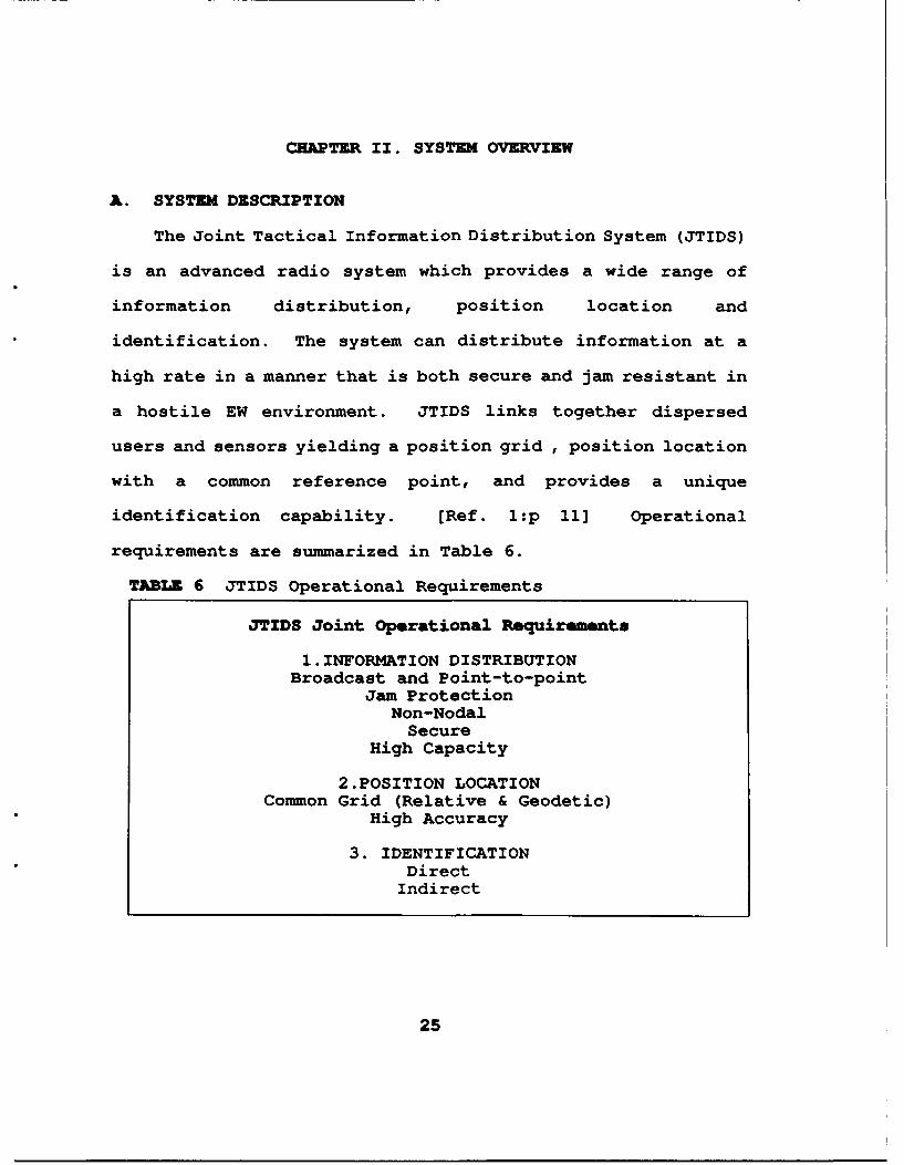
A. SYSTEM DESCRIPTION
The Joint Tactical Information Distribution System (JTIDS)
is an advanced radio system which provides a wide range of
information distribution, position location and
identification. The system can distribute information at a
high rate in a manner that is both secure and jam resistant in
a hostile EW environment. JTIDS links together dispersed
users and sensors yielding a position grid , position location
with a common reference point, and provides a unique
identification capability. [Ref. 1:p 11] Operational
requirements are summarized in Table 6.
TABLE 6 JTIDS Operational Requirements
JTIDS Joint Operational Requirements
1.INFORMATION DISTRIBUTIONBroadcast and Point-to-point
Jam ProtectionNon-NodalSecure
High Capacity
2.POSITION LOCATIONCommon Grid (Relative & Geodetic)
High Accuracy
3. IDENTIFICATIONDirect
Indirect
25

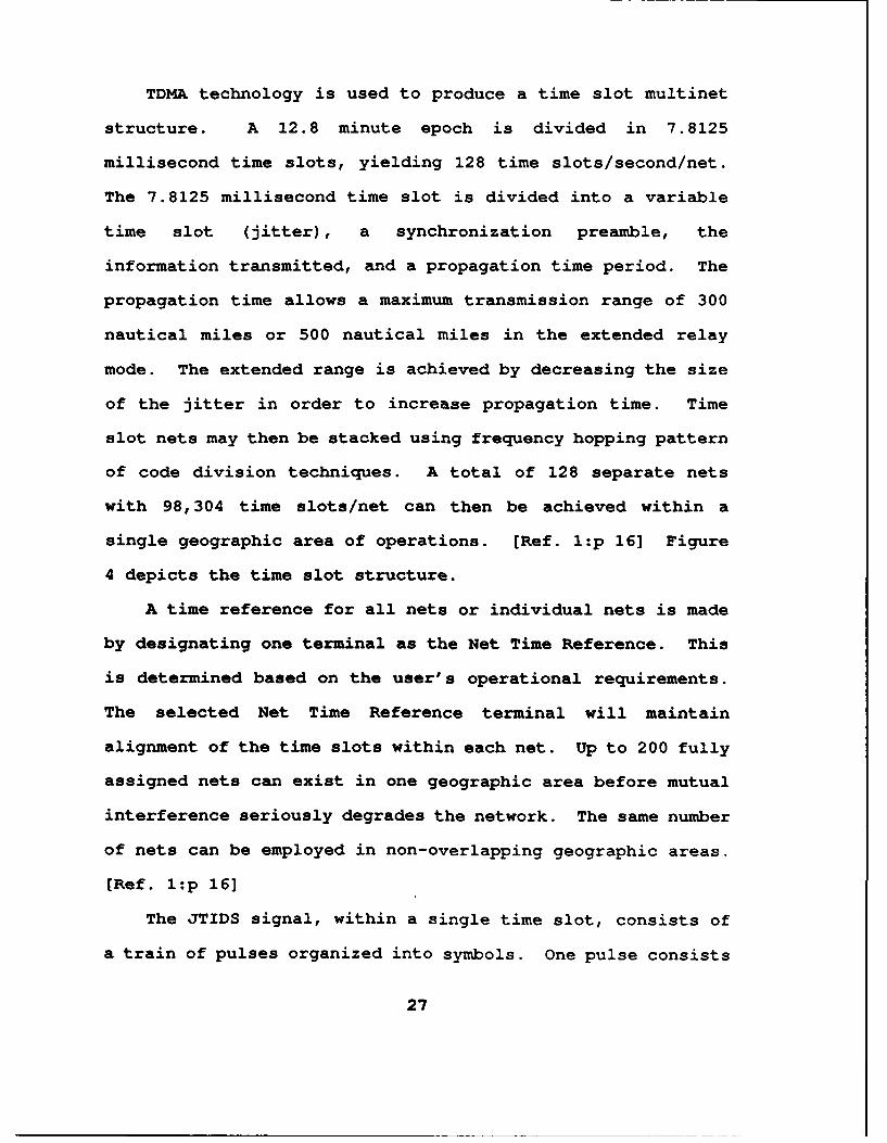
B. SYSTEM TECHNOLOGY
JTIDS utilizes a bit oriented message form of information
which enables the use of extremely efficient digital message
structure as in TADIL J, digital voice, or character oriented
messages. The system operates within the 960 to 1215 MHz
radio frequency band. This insures compatibility with civil
Distance Measuring Equipment (DME), Military Tactical Air
Navigation equipment (TACAN). JTIDS uses Time Division
Multiple Access (TDMA) technology to meet integrated
operational requirements. [Ref. l:p 11] The structure of
TDMA design is depicted in Figure 3.
cc MESSAGE
/ DOUBI F PUSE/ SYMOUL SINGLEI PULSE SYMBOL - 13 siec
'. DOUDLE PULSE SYMBOL . 21 sec
/ 64 66 64 66 sa
32 CHIPS SYMBOL CAN BE SINGLE OR DOUBLE PULSE
JTIDS flI !PULSE 0 * PULSES FEOUENCY HOPPED
0 32PNCHIPS -MHzlRATE
* ENCODES S BITS OF DATACCSKSBITS . 32 CHIPS32CHIPSARECPSM
CHIP
200 nsec
Figure 3 JTIDS Signal Structure
26
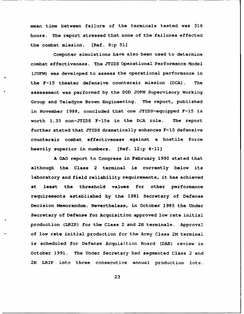
TDMA technology is used to produce a time slot multinet
structure. A 12.8 minute epoch is divided in 7.8125
millisecond time slots, yielding 128 time slots/second/net.
The 7.8125 millisecond time slot is divided into a variable
time slot (jitter), a synchronization preamble, the
information transmitted, and a propagation time period. The
propagation time allows a maximum transmission range of 300
nautical miles or 500 nautical miles in the extended relay
mode. The extended range is achieved by decreasing the size
of the jitter in order to increase propagation time. Time
slot nets may then be stacked using frequency hopping pattern
of code division techniques. A total of 128 separate nets
with 98,304 time slots/net can then be achieved within a
single geographic area of operations. [Ref. l:p 16] Figure
4 depicts the time slot structure.
A time reference for all nets or individual nets is made
by designating one terminal as the Net Time Reference. This
is determined based on the user's operational requirements.
The selected Net Time Reference terminal will maintain
alignment of the time slots within each net. Up to 200 fully
assigned nets can exist in one geographic area before mutual
interference seriously degrades the network. The same number
of nets can be employed in non-overlapping geographic areas.
[Ref. l:p 16]
The JTIDS signal, within a single time slot, consists of
a train of pulses organized into symbols. One pulse consists
27
INFORMATION BITS PER SLOTI7 ERMINAL CAPACITY = Kb/Sl
WITHEDC W/O EDC
STANDARD i ISrr,11 D P 22 46DOUBLEPULSE .J 81 159.51
PACKED 2 I r ~ ri, l450 930SINGLE PULSE J S11 D 7 157.61 11 9.01
PACKED 2 iiD ~450 930DOUBLE PULSE S H D D " 157.61 1119.01
PACKED4 llT900 1860SINGLE PULSE S H D D ) D P i 1115.21 1238.0
S: SYNC J a JITTERH = HEADER P a PROPAGATION0a DATA EDC - ERROR DETECTION ANOCORRECTION
Figure 4 JTIDS Time Slot Structures
of 5 bits of data in one 6.4 microsecond unit of time in a 13
microsecond symbol or 2 pulses in each 26 microsecond symbol.
The latter method still contains 5 bits of data within the two
pulses. Each pulse containing the 5 bits are represented by
a 32-chip Cyclic Code Shift Keying (CCSK) pattern. The
resulting pulse is then Continuous Phase Shift Modulated
(CPSM) at a rate of 5MHz. The resultant signal symbols are
then interleaved on transmission. Employment of the frequency
hopping mode (Mode 1) dictates that each successive pulse is
randomly transmitted using one of the 51 available
frequencies. In the non-frequency hopping mode (Modes 2, 3
and 4) all pulses are transmitted on 969 MHz. [Ref. 13:p 6]
28
C. MESSAGE STRUCTURE
Different information capacities are obtained through the
use of differing mezsage structures. The differing
information capacities can then be matched to the type of
information desired for transmission. The standard is the
double pulse structure which is the most rugged for
operational performance. Some structures enable the time slot
to be packed with two or four messages through the use of the
single pulse structure or deletion of the jitter or both.
Error detection and correction is accomplished through use of
the Reed-Solomon method. The error and correction portion of
the transmission may be deleted if considered unnecessary,
thereby T-roviding additional bits for operational information.
[Ref. l:p 17]
JTIDS currently uses two message formats. The Interim
JTIDS Message Specification (IJMS) and TADIL J message were
developed by the JTIDS Message Standards Working Group (JMSWG)
of the Joint Interoperability Program for Tactical Command and
Control Systems (JINTACCS). Both message formats provide
fixed format and free text messages. Additionally, TADIL J
provides a variable message format structure. Reed-Solomon
data code words are used to embed information for both message
specifications. A shortened Reed-Solomon code word is
incorporated into the header yielding a 35 bit information
header. The header includes the type of message, the source
29
address of the originator, and security information to decode
the transmission. [Ref. 7:p 3]
The LJMS message contains 225 bits within a standard time
slot. Message labelling provides 128 possible message
formats, only 36 of which have been defined. These messages
include position reports, track reports, strobes, special
reports and command and control messages. There are a limited
number of net management messages available. The entire menu
of messages available are based on the JCS Publication 10 set
of messages. The data field portion of the message
corresponds directly to the JCS Publication 10 data fields,
but have been expanded to allow future use. There are only
two major exceptions here. The first is the position
reference which uses longitude and latitude rather than the
rectanglinear coordinate system. The second exception is the
basic reference number which is 5 octal digits rather than 4.
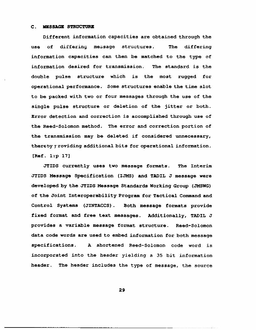
(Ref. 13:p 8] Figure 5 contains a breakdown of the IJMS
Structure.
TADIL J messages consist of one or more 75 bit message
words. Four error detection bits, 70 information bits and 1
spare bit are contained in one word. This composition
provides a modular message structure allowing single or
multiple messages to be transmitted in one time slot.
Messages include position reports, track reports, special
reports, strobes, weapons control and command and control
messages. Message labelling permits 256 message types
30
TIME SLOT
S 11 / I I I, \S SYNCNM4 HEADER0. DATA
//
//
~ DEFINESCONTENT OF MESSAGE
COTE T I? CA T1 DATA FIELDS PARITY
0 ISFED 4 13 206 12
I 225
Figure 5 IJMS Message Structure
including a full set of net management messages. The JCS
Publication 10 is also the model for TADIL J messages. There
is also a variable message format which allows the user to
compose messages of varied content and format. [Ref. 7 :p 8]
Figure 6 contains a breakdown of the TADIL J message format.
Interoperability of the two message formats is achieved
through a bilingual capability for all Class 2 terminals.
D. INFOR~MATION DISTRIBUTION
JTIDS' unique architecture and signal structure provide a
large number of information distribution techniques which can
be designed to meet specific user requirements. Participation
groups are formed by pooling time slots. Nets are created by
assigning these groups various net access and relay modes.
31
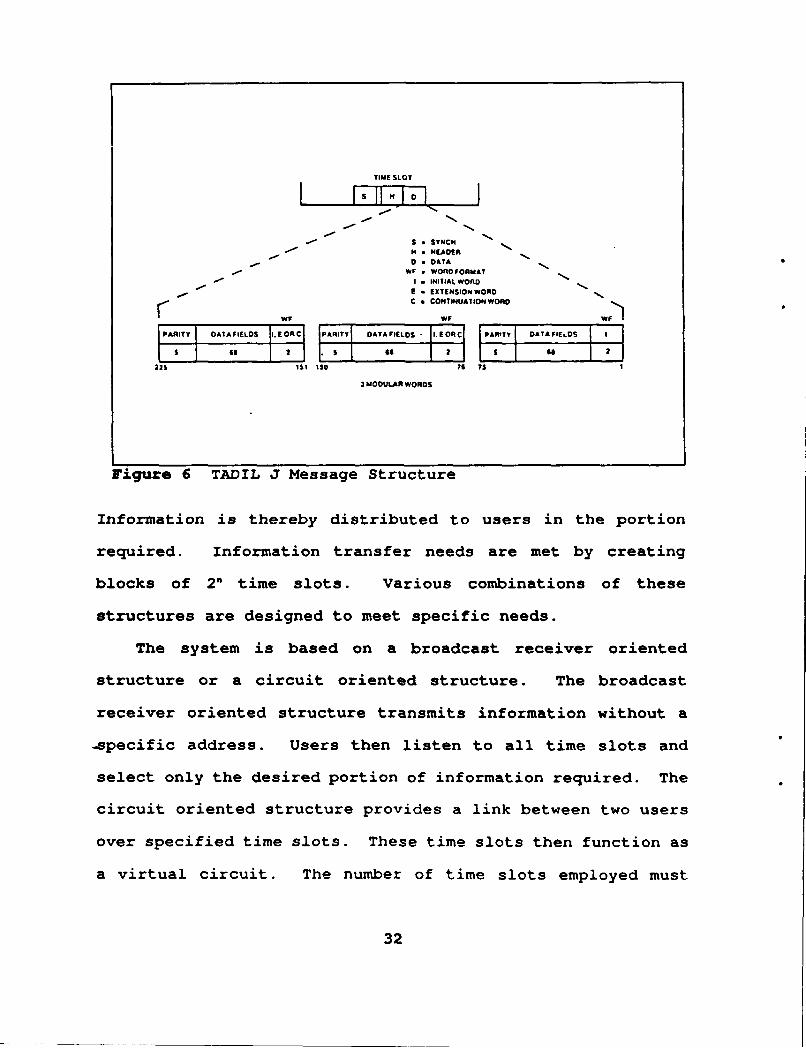
TIME SLOT
S SNCH' H •HU.DfR
- O DATAWF * WOROFOAMAT
- * I - INITIALWOAO- -U E ET:NSIONWORD~C •CONTINUAT ION WORD F
WF WIC W)
PARITY ATAFIELDSI.EORC 1TY DATAFIELOS I.EOAC IpAYy DATAFIELDS I
is GI2 e- S 2e
22s ist ISO i1 s 1
3 MODULAR WORDS
Figure 6 TADIL J Message Structure
Information is thereby distributed to users in the portion
required. Information transfer needs are met by creating
blocks of 20 time slots. Various combinations of these
structures are designed to meet specific needs.
The system is based on a broadcast receiver oriented
structure or a circuit oriented structure. The broadcast
receiver oriented structure transmits information without a
-.specific address. Users then listen to all time slots and
select only the desired portion of information required. The
circuit oriented structure provides a link between two users
over specified time slots. These time slots then function as
a virtual circuit. The number of time slots employed must
32
match the desired bit rate of the virtual circuit. [Ref. 1:p
24]
Z. RELAY FUNCTION
Basic coverage of the JTIDS network can be extended from
300 nautical miles to a maximum range of 500 nautical miles by
retransmitting the message content of the time slots. This is
accomplished by retransmitting messages received in one time
slot into another specific time slot. This function, when
selected, is automatic and is transparent to the user. Two
relay techniques may be employed to extend the range of the
network. The two methods are paired slot relay and
repromulgation relay. [Ref. 1:p 25]
1. Paired Slot Relay
In this relay method one or more sets of timz slots
are designated as blocks. These blocks are then paired with
other blocks of the same size for retransmission. Additional
blocks can be linked together when more than one relay hop is
desired. Each terminal so assigned can then relay on a
conditional or unconditional basis. In the unconditional
mode, the designated terminal relays continuously in the
designated time slots. In the conditional mode, the terminal
relays messages received in the slots designated to be relayed
only if that terminal has the best coverage. If there is
another terminal with better net coverage, it will serve as
the relay terminal. [Ref. 13:p 12]
33
2. Repromulgation Relay
The originator of the message determines how often the
particular message will be relayed and the pattern of time
slots that will be used in the repromulgation method. All
other designated receivers will be assigned % listen to the
pool of slots designated for transmission. The number of
successive relay hops is then determined by the receiver. If
the designated number of hops has not been reached, the
receiving terminal will retransmit the message in the
appropriate time slot. If the last hop has been attained, the
receiving terminal stops transmission. Within three time
slots, the originator can transmit over the same sequence of
time slots. Messages transmitted over a given sequence of
time slots may be stacked one immediately following another.
[Ref. 13:p 13]
F. ACCESS MODES
A variety of access modes are provided for the JTIDS
system. These modes define which terminal can transmit in a
given time slot. Access modes are designed to match
predetermined information distribution needs. There are three
access modes available to network planners.
1. Dedicated Access
In this access mode, specific users are assigned
specific time slots for transmission of messages. The time
slot remains vacant when the designated user is not
34
transmitting. The number of slots assigned to a given user
will depend upon that user's particular needs. These
designated time slots may only be reused in a different
geographical area.
2. Contention Access
A block of time slots is designated, in this method,
to be shared by a number of users. Each user randomly selects
a time slot from the block for transmission. All users within
the group listen to the entire block of time slots when not
transmitting. The amount of information to be transmitted or
the rate at which the information is to be transmitted will
determine the number of time slots utilized.
3. Distributed Reservation Access
The final access mode again determines a block of time
slots to be shared by a group of users. Sequentially, the
users determine how many time slots they will need in the
future. Reservation messages are used to identify each user's
future requirements. These messages are transmitted in the
dedicated access mode. The previous reservation is used to
determine the number of time slots remaining for use within
the block. In turn, the remaining users transmit their
reservation message to the reservation group. This is a
cyclic, ongoing process and provides the opportunity for all
users to adjust reservations based on changing needs. [Ref.
l:p 27]
35
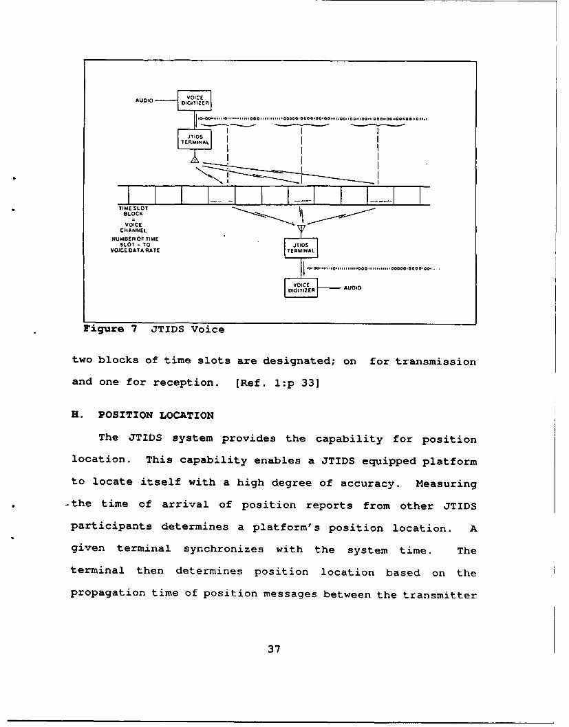
G. VOICE
Digitized voice data transmisbion is incorporated as a
function of the JTIDS system. The audio signal is digitized
into a bit stream which is then divided into time intervals
which correspond to time slot lengths. Transmission then
occurs in periodic time slots. The periodic time slots are
received at the designated receivers and are recombined into
the digitized voice bit stream. A voice digitizer in the
terminal returns the audio signal. The use of JTIDS error
detection and correction will depend upon the error correction
function that is present in the voice digitizer.
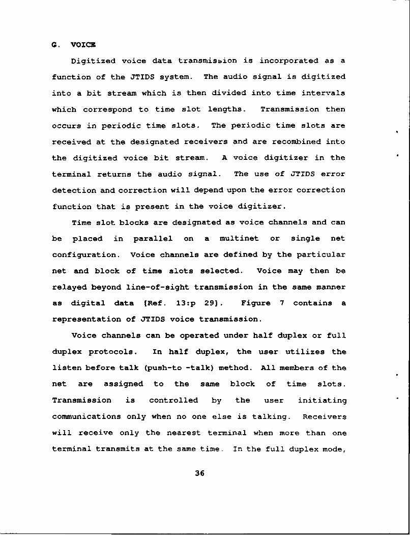
Time slot blocks are designated as voice channels and can
be placed in parallel on a multinet or single net
configuration. Voice channels are defined by the particular
net and block of time slots selected. Voice may then be
relayed beyond line-of-sight transmission in the same manner
as digital data [Ref. 13:p 291. Figure 7 contains a
representation of JTIDS voice transmission.
Voice channels can be operated under half duplex or full
duplex protocols. In half duplex, the user utilizes the
listen before talk (push-to -talk) method. All members of the
net are assigned to the same block of time slots.
Transmission is controlled by the user initiating
communications only when no one else is talking. Receivers
will receive only the nearest terminal when more than one
terminal transmits at the same time. In the full duplex mode,
36
AUDIO VOICEDIGITIZER
I ITRINAL
I 1* I
* TIME SLOTBLOCKVOICE
CHANNEL
NUMBER OF TIMESLOT - TO JTIOS
VOICEDATARATE TERMINAL
[ E AUDIO
Figure 7 JTIDS Voice
two blocks of time slots are designated; on for transmission
and one for reception. [Ref. l:p 33]
H. POSITION LOCATION
The JTIDS system provides the capability for position
location. This capability enables a JTIDS equipped platform
to locate itself with a high degree of accuracy. Measuring
-the time of arrival of position reports from other JTIDS
participants determines a platform's position location. A
given terminal synchronizes with the system time. The
terminal then determines position location based on the
propagation time of position messages between the transmitter
37
and itself. The propagation time and the transmitter's
reported position permits the terminal to determine its range
from the transmitter. Similar measurements are taken from
other transmitters or subsequent transmissions from the first
transmitter. These measurements are used to triangulate the
terminal's position. Once the terminal's position location
has been accurately determined, it will periodically transmit
position reports for other platforms to use. [Ref. l:p 35]
I. IDENTIFICATION
Periodic secure position and identification messages are
transmitted to* provide direct identification among all
platforms equipped with JTIDS. Position location and command
and control functions are also supported with these messages.
JTIDS position and identification messages that are received
can be verified against radar tracks and/or intelligence
information. The periodicity of reporting can be varied to
coincide with the needs of the platform. An aircraft will be
required to broadcast its identification and position much
more often than a ground station. [Ref. 1:p 37]
J. CLASSES OF TERMINALS
There are three classes of terminals that are each
designed to meet the requirements of a general grouping of
users:
38
" Command and Control Users. The Class 1 Terminal isdesigned for use in large airborne and ground basedcommand and control elements.
" Small Platform Users. The Class 2 Terminal is designedfor use in small command and control elements and sometactical aircraft.
* Missile and Manpack Users. The Class 3 Terminal is beingdesigned for use with very small units including manpacks,missiles and voice-only uses. [Ref. l:p 41]
1. Class 1 Terminal
The Class 1 command and control terminal is designed
for use in U.S. and NATO E-3As, NATO air defense C2 systems
and in the JTIDS Adaptable Surface Interface Terminal (ASIT).
The terminal can operate in all four JTIDS modes. It
processes only the standard JTIDS message format. Both the
normal and extended range modes may be employed. The Class 1
terminal can operate as a Net Time Reference station, but does
not have a position location function. It may function as a
position reference station with an external position data
source. The terminal can transmit in only one net and can
receive on a maximum of three different nets. The message
format used is the Interim JTIDS Message Standard (IJMS) . The
unit weighs 400 pounds and occupies 6.5 cubic feet of space.
It is rack mounted to enable employment with the various users
it supports. (Ref. 14]
2. Class 2 Full Scale Development Terminal
The Class 2 (FSD) terminal is designed for small
platform users. The terminal contains an Interface Unit (IU)
39
which allows integration with a large number of diversified
platforms. Versions are currently available for the F-14 and
F-15 tactical aircraft and some Army elements.
The Class 2 terminal can operate in TDMA modes 1,2
and 4. Mode 3 is not operationally required for the terminal.
It processes the TADIL J message structure and can process
either the single or double pulse waveforms. Normal and
extended range modes can be employed. The terminal can
transmit and receive on any JTIDS net. The terminal also has
a position location capability and a Continuous Variable Slope
Delta (CVSD) voice capability. An analog-digital conversion
may be employed outside the terminal to accommodate other
voice rates. Incorporation of a TACAN function into the Class
2 terminal eliminates the need for separate aircraft TACAN
equipment.
A bilingual capability allows the Class 2 terminal to
communicate with all Class 1 terminals which employ the IJMS
message standard. All IJMS messages that are sent by existing
IJMS terminals can be received and transmitted by the Class 2
terminal. Software in the Subscriber Interface Computer
Program translates IJMS messages into TADIL J message for use
by the Class 2 user. It also translates TADIL J into IJMS for
transmission into the net. Users of Class 2 terminals can
determine which messages that are received will be translated
and whether IJMS, TADIL J or both message standards will be
used for transmission. (Ref. 14]
40
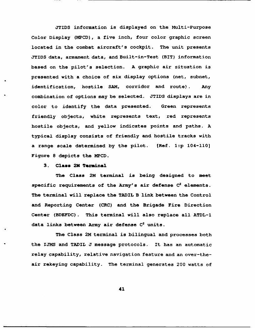
JTIDS information is displayed on the Multi-Purpose
Color Display (MPCD), a five inch, four color graphic screen
located in the combat aircraft's cockpit. The unit presents
JTIDS data, armament data, and Built-in-Test (BIT) information
based on the pilot's selection. A graphic air situation is
presented with a choice of six display options (net, subnet,
identification, hostile SAM, corridor and route). Any
combination of options may be selected. JTIDS displays are in
color to identify the data presented. Green represents
friendly objects, white represents text, red represents
hostile objects, and yellow indicates points and paths. A
typical display consists of friendly and hostile tracks with
a range scale determined by the pilot. [Ref. l:p 104-110]
Figure 8 depicts the MPCD.
3. Class 2M Terminal
The Class 2M terminal is being designed to meet
specific requirements of the Army's air defense C2 elements.
The terminal will replace the TADIL B link between the Control
and Reporting Center (CRC) and the Brigade Fire Direction
Center (BDEFDC). This terminal will also replace all ATDL-1
data links between Army air defense C2 units.
The Class 2M terminal is bilingual and processes both
the IJMS and TADIL J message protocols. It has an automatic
relay capability, relative navigation feature and an over-the-
air rekeying capability. The terminal generates 200 watts of
41
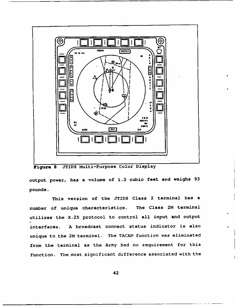
OWU, no
Figure 8 JTIDS Multi-Purpose Color Display
output power, has a volume of 1.3 cubic feet and weighs 93
pounds.
This version of the JTIDS Class 2 terminal has a
number of unique characteristics. The Class 2M terminal
utilizes the X.25 protocol to control all input and output
interfaces. A broadcast connect status indicator is also
unique to the 2M terminal. The TACAN function was eliminated
from the terminal as the Army had no requirement for this
function. The most significant difference associated with the
42
Class 2M terminal is its lack of the digital voice capability.
The terminal has no ability to participate on the digital
voice channel of the JTIDS net to which it is assigned. [Ref.
15]
4. Class 2H Terminal
The Class 2H terminal is under development to meet the
needs of the Navy E-2C and C2 elements. It will also replace
replace Class 1 terminals previously fielded to Air Force E-3A
AWACS aircraft. The terminal was approved to meet
requirements for extended transmission range.
The 2H terminal has a transmission output power of
1000 watts. This increased power capability greatly extends
the terminal's range of transmission. The terminal processes
both message protocols. It has an automatic relay capability
and relative navigation feature. The navigation feature
provides a new capability to the E-3A AWACS. The terminal has
a TACAN capability and over-the-air rekey function. It's
volume is 5.2 cubic feet and weighs 340 pounds. [Ref. 15]
5. Class LV Terminal
The Low Volume terminal is currently in the concept
development stage. It is being designed to meet requirements
under the third phase of JTIDS development. This terminal is
to be employed with manpacks, missiles and very small C2
elements.
43
The LV terminal has the same basic capabilities as the
Class 2 series of terminals. These capabilities include 200
watts of output power, bilingual message protocal processing,
automatic relaying, digital voice, TACAN and over-the-air
rekeying. The major difference in this terminal is its size.
The LV terminal's volume is 0.6 cubic feet and weighs 64
pounds. It also has a lower data processing capability.
[Ref. 15] Table 7 contains a summary of terminal
capabilities.
44
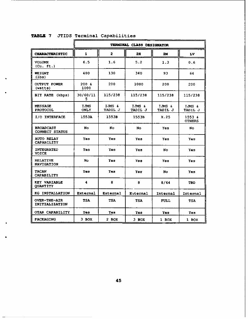
TABLE 7 JTIDS Terminal Capabilities
TERMINAL CLRSS DESIGNATOR
VOLUME 6.5 1.6 5.2 1.3 0.6(Cu. ft.)
WEIGHT 400 130 340 93 64(ibs)
OUTPUT POWER 200 & 200 1000 200 200(watts) 1000
BIT RATE (kbps) 30/60/11 115/238 115/238 115/238 115/2385
MESSAGE IJMS IJMS & IJMS & IJMS & IJMS &PROTOCOL ONLY TADIL J TADIL J TADIL J TADIL J
I/O INTERFACE 1553A 1553B 1553B X.25 1553 &OTHERS
BROADCAST No No No Yes NoCONNECT STATUS
AUTO RELAY Yes Yes Yes Yes YesCAPABILITY
INTEGRATED Yes Yes Yes No YesVOICE
RELATIVE No Yes Yes Yes YesNAVIGATION
TACAN Yes Yes Yes No YesCAPABILITY
KEY VARIABLE 4 8 8 8/64 TBDQUANTITY
KG INSTALLATION External External E:-ternal Internal Internal
OVER-THE-AIR TSA TSA TSA FULL TSAINITIALIZATION
OTAR CAPABILITY Yes Yes Yes Yes Yes
PACKAGING 3 BOX 2 BOX 3 BOX 1 BOX 1 BOX
45
a3APTZR III. NZTWORK INAGflNT
A. DZFINITION
Network management of JTIDS is the process of directing
the use of specific terminal capabilities and net
configurations to meet mission requirements. Appropriate
terminal parameters are selected for each member terminal.
Transmission requirements for each platform are met through
assignment of appropriate time slots. Compatible
initialization parameters are determined to ensure terminal
communications. In addition, network support functions must
be assigned (i.e. Terminals designated to serve as Net Time
References). This broad scope of activities is referred to as
Network Management. [Ref. l:p 33]
B. NETWORK MAmAGINTOVERVIEW
The required exchange of information among network
participants is met through the development of network
designs, by the JTIDS system manager. These network designs
can range from simple Class 1 terminal networks to more
complex networks containing both Class 1 and 2 terminals. A
network involving only Class 1 terminals is described,
followed by a description of network management of a more
complex system incorporating both terminal types.
46
1. Class 1 Terminal Network
Current implementation of Class 1 JTIDS networks
involve E-3A AWACS and Control and Reporting Centers (CRCs).
The operation of a JTIDS network can be conceptualized as a
"data bus in the sky." This analogy represents the technology
of Time Division Multiple Access (TDMA). Under TDMA, each
user is assigned specific time slots in which to transmit.
Computers, internal to each terminal, receive their time slot
assignments through the loading of software parameters. The
software directs time slots that will be used for transmission
by the terminal. Every time slot contains a series of pulses,
each of which can encode 225 bits of formatted data or 465
bits of free text information. 128 time slots are available
every second to users in a JTIDS net. All terminals listen to
the net when they are not transmitting. This reception occurs
automatically and is the default condition of the Class 1
terminal. The JTIDS Class 1 network is a receiver oriented
communications system. Each terminal receives all transmitted
information on the network. The individual user then filter
the information as necessary to meet their requirements.
[Ref. l:p 16]
A Class 1 terminal only network contains a single net.
It is not capable of participating in networks where multiple
nets are operating simultaneously. Multiple nets are
developed through the use of frequency division multiplexing.
All members of a Class 1 network operate on a single
47
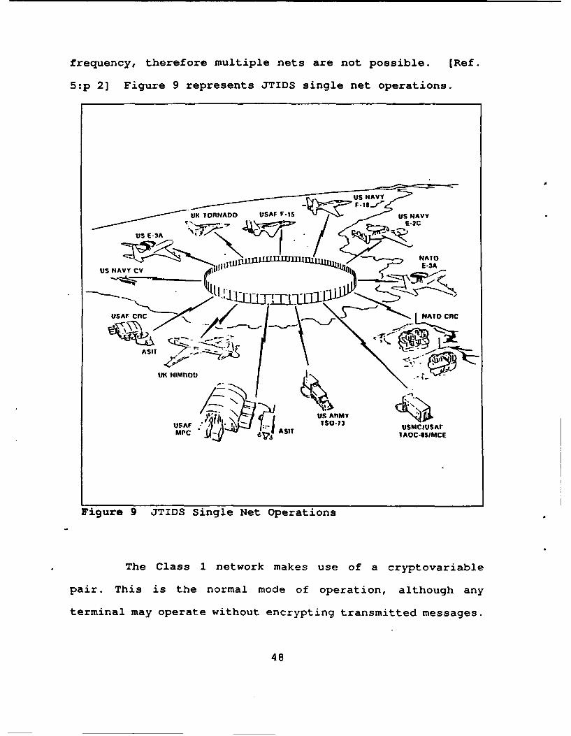
frequency, therefore multiple nets are not possible. [Ref.
5:p 2] Figure 9 represents JTIDS single net operations.
UK ionNAD USAF.--I US NAVY
US E-3A
LM TNAil)
' ;IAUS NAVY CV IIIllh.IL l. t] u1 1 E*S .
USAF ecfl / AIO cnc
ASIT
UK NIMPIOU -
USAF- USMCIUSArMPC SIT AOC-USIMCE
Figure 9 JTIDS Single Net Operations
The Class 1 network makes use of a cryptovariable
pair. This is the normal mode of operation, although any
terminal may operate without encrypting transmitted messages.
48
All messages are encrypted for transmission and decrypted for
reception through use of the current cryptovariable. The
transmission frequency appears to be a random series of pulses
to any receiver not possessing the cryptovariable. Class 1
terminals are loaded with only two cryptovariables. The first
cryptovariable is used for the first day of operation. At the
end of the 24 hour period, the first variable is destroyed by
the terminal and the second variable is selected for the next
day's use. The terminal is loaded with a new pair of
cryptovariables upon completion of the second day. There is
no confusion on the Class 1 net as to which variable is in use
during any given time period. [Ref. 5:p 3]
Messages are segregated by the transmitting Class 1
terminal. Only three classes of messages exist for this
purpose. The message classes are P messages which carry the
transmitter's identity, status and position, all other data
messages, and voice messages. Each class of message is
designated for transmission in specific time slots. Any
receiver in the net can select a specific class of mes.ages
and ignore the rest. The terminal must listen to all incoming
messages and then screen them for the desired information.
[Ref. 13:p 12]
Time slots are assigned to a specific Class 1 terminal
in groups called time slot blocks. The number of time slots
contained in a time slot block must be an integral power of
two. A terminal can be alloted a time slot block which may
49
contain one time slot, two slots, four slots, eight slots,
etc. For example, if a terminal requires 24 time slots per 12
second JTIDS frame for data transmissions it would be assigned
one time slot block of 16 time slots and one block of 8 time
slots. A terminal may be assigned a total number of time
slots not equal to a power of two by assigning several time
blocks whose sum of time slots is greater than or equal to the
desired number of slots. Terminals requiring 22 time slots
per frame, which is not a power of two, would be assigned the
same blocks of time slots as above. This would result in two
extra slots per frame. Class 1 terminals may be assigned a
total of four time slot blocks, one is for P messages and the
remaining three for data transmission. Additionally, the
terminal can be assigned one block for digital voice and as
many as six pairs of smaller blocks for transmission relay.
Each time slot block requires only four initialization
parameters. The first three parameters identify a specific
time slot block. The final parameter identifies the class of
message that will be transmitted in that block. [Ref. l:p 43]
Class 1 terminals have relatively few features which
need to be enabled or disabled during initialization.
Selection of normal or extended range mode is an example of
one of these features. The net manager may select the
extended range mode which would reduce that terminal's anti-
jam capability due to a reduction in the anti-jam provision of
the transmitted signal. This assignment of terminal
50
capabilities requires that choices be made by the network
manager of initialization parameters that will result in the
desired JTIDS network. The default condition of the Class 1
terminal is "receive only." This condition reduces the
workload for the metwork manager because each time slot not
specifically assigned will automatically default to the
receive conditions. There are only 15-20 parameters that must
be selected to implement this network. [Ref. 5:p 13]
In summary, the network manager's tasks to implement
a Class 1 network are as follows:
" Allocation of time slots to terminals.
" Selection of implemented features.
" Assignment of initialization parameters.
The network manager must ensure that all parameters
are distributed to terminal operators, that they are properly
loaded and validated, and that the network performs properly
during operation. Any changes are made on the ground by the
network manager and are loaded into individual terminals as
the users return to base or are couriered to other ground
units. These responsibilities will remain consistent for
multiple nets involving Class 1 and 2 terminals.
2. Class 1 and 2 Terminal Networks
A Class 1 terminal only network provides increased
capabilities to air battle participants over non-JTIDS
equipped participants. The network is receiver oriented and
51
is therefore highly flexible. This network configuration
allows significantly reduced preplanning regarding design of
a JTIDS network. Data distribution requirements at the
theater level have dramatically increased the demand for JTIDS
communication capabilities. Numerous capabilities have been
incorporated into the Class 2 series of terminals to meet
these increased requirements. The complexity of network
design has increased with each new capability. [Ref. 5:p 5]
Employment of Class 2 terminals in a JTIDS network
meets the required increase in network capacity. A JTIDS
terminal is assigned specific time slots in which to transmit.
Narrow band jamming is defeated by pseudo-randomly selecting
a new frequency for each pulse transmitted. The process of
selecting frequencies is part of the encryption process,
preventing the enemy from ascertaining the pattern of
frequency hopping. Selection of different frequency hopping
patterns allows the simultaneous operation of multiple JTIDS
nets. [Ref. 1:p 16]
Multiple nets are produced by assigning unique time
slots to each terminal with a unique frequency hopping
pattern. A terminal transmits data pulses during its assigned
time slots under its frequency hopping pattern. A second
terminal transmits its data pulses over a second frequency
hopping pattern. Any terminals desiring receipt of the first
terminal's transmission are set to the first terminal's
frequency hopping pattern. The same requirement exists for
52
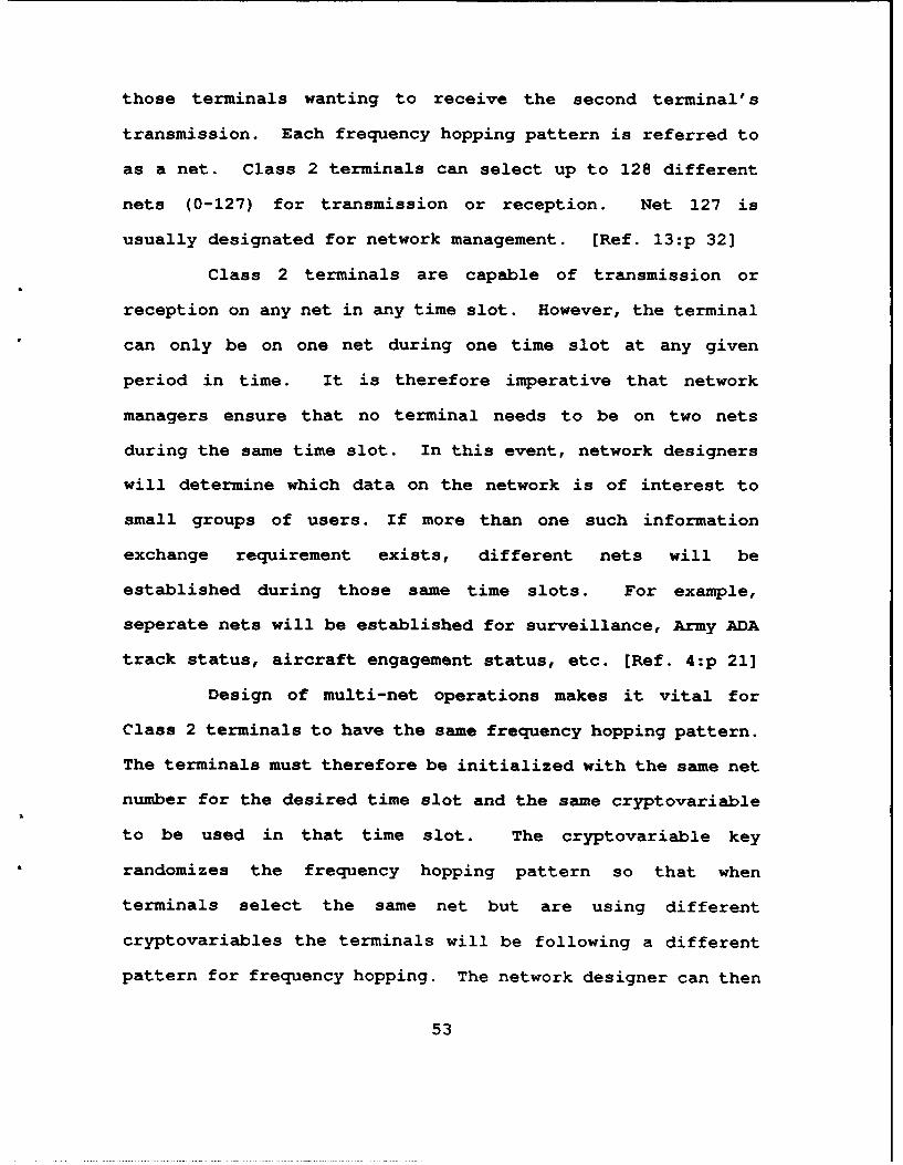
those terminals wanting to receive the second terminal's
transmission. Each frequency hopping pattern is referred to
as a net. Class 2 terminals can select up to 128 different
nets (0-127) for transmission or reception. Net 127 is
usually designated for network management. [Ref. 13:p 32]
Class 2 terminals are capable of transmission or
reception on any net in any time slot. However, the terminal
can only be on one net during one time slot at any given
period in time. It is therefore imperative that network
managers ensure that no terminal needs to be on two nets
during the same time slot. In this event, network designers
will determine which data on the network is of interest to
small groups of users. If more than one such information
exchange requirement exists, different nets will be
established during those same time slots. For example,
seperate nets will be established for surveillance, Army ADA
track status, aircraft engagement status, etc. [Ref. 4:p 21]
Design of multi-net operations makes it vital for
Class 2 terminals to have the same frequency hopping pattern.
The terminals must therefore be initialized with the same net
number for the desired time slot and the same cryptovariable
to be used in that time slot. The cryptovariable key
randomizes the frequency hopping pattern so that when
terminals select the same net but are using different
cryptovariables the terminals will be following a different
pattern for frequency hopping. The network designer can then
53
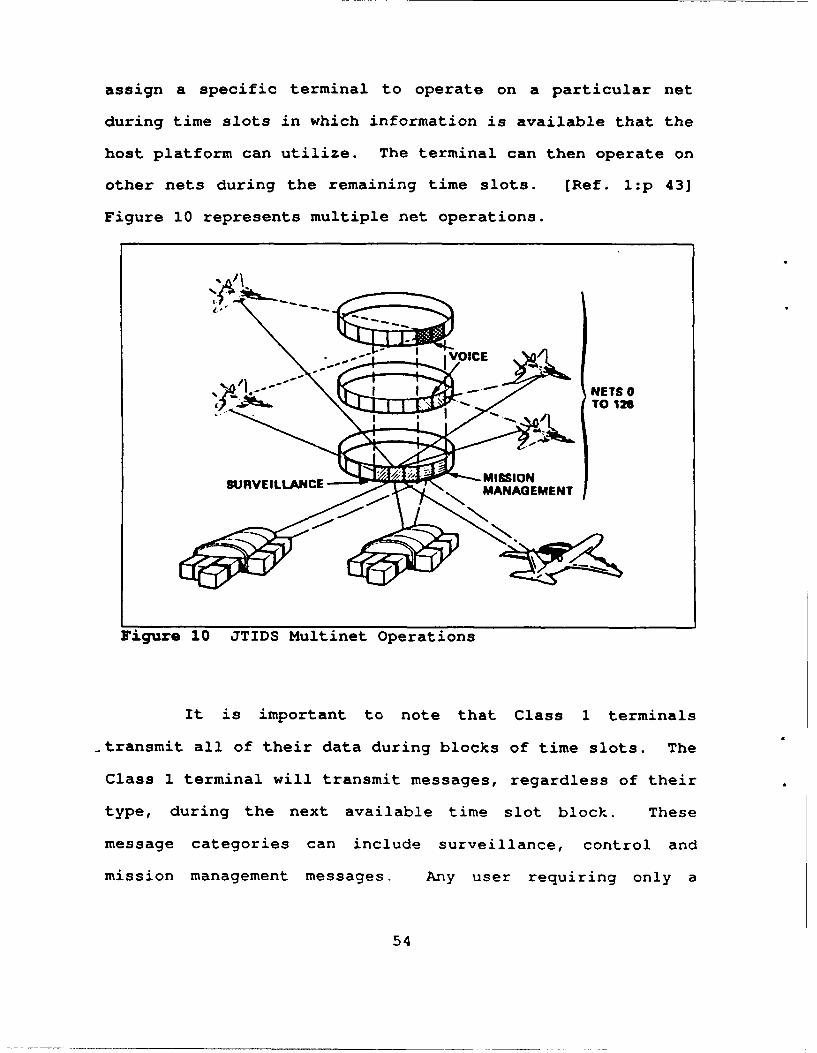
assign a specific terminal to operate on a particular net
during time slots in which information is available that the
host platform can utilize. The terminal can then operate on
other nets during the remaining time slots. [Ref. l:p 43]
Figure 10 represents multiple net operations.
NETS 0T 126
SURVEILLACE MISSION
Figure 10 JTIDS Multinet Operations
It is important to note that Class 1 terminals
-transmit all of their data during blocks of time slots. The
Class 1 terminal will transmit messages, regardless of their
type, during the next available time slot block. These
message categories can include surveillance, control and
mission management messages. Any user requiring only a
54
specific category of messages would have to listen to all
Class 1 transmissions to ensure reception of the desired
information. This limitation was eliminated in the Class 2
series terminal design by having each message category
assigned to a specific time slot. [Ref. 5:p 6]
Eighteen different subject categories were designed
into the Class 2 terminal to overcome Class 1 limitations.
The subject categories are referred to as Network
Participation Groups. There are also 480 categories of
potential message distributions, known as Needline
Participation Groups. The Class 2 terminal initialization
process directs time slots to be selected specifically for
each category of messages to be transmitted. For example,
surveillance information is directed to be transmitted in
specific time slots on net 0 and control messages are to be
transmitted on net 5 during a different set of time slots.
Any terminal requiring receipt of this surveillance
information must be directed to listen to net 0 during the
appropriate set of time slots. All terminals that are
required to transmit surveillance information are assigned
time slots on net 0 for this purpose. All JTIDS members that
require surveillance information will be assigned to listen to
all time slots on net 0 which contains surveillance
information. These time slots will coincide with the set of
time slots assigned for surveillance transmission.
55
Transmitting terminals will also be directed to listen to all
other surveillance transmissions on net 0. [Ref. 5:p 7]
This design process continues for the development of
subsequent nets. It is the network designer's responsibility
to ensure that each JTIDS participant is able to transmit and
receive all assigned information in time slots that are
mutually exclusive. This higher level network is no longer
receiver oriented. Each terminal must know when it is to
transmit and on which net. The terminal must also be told
when and where it is to listen. [Ref. 13:p 29]
The Class 1 terminal is of a simpler design and only
uses one cryptovariable pair for transmission. Multiple
cryptovariables are available on the Class 2 terminal during
any given time slot. Therefore the Class 2 terminal must know
which cryptovariable is to be used in which time slot. In
addition, the Class 2 terminal has a great many more features
than the Class 1 terminal. The Class 1 terminal's default
condition has widespread utilization in a Class 1 terminal
only network. The Class 2 terminal's default condition has
very limited utilization in the mixed terminal network. (Ref.
13:p 55]
The increased number of features on the Class 2
terminal facilitates more initialization parameters. The
parameters enable the terminal to determine which function is
to be performed in any given time slot. Initialization
parameters will assign appropriate time slots for
56
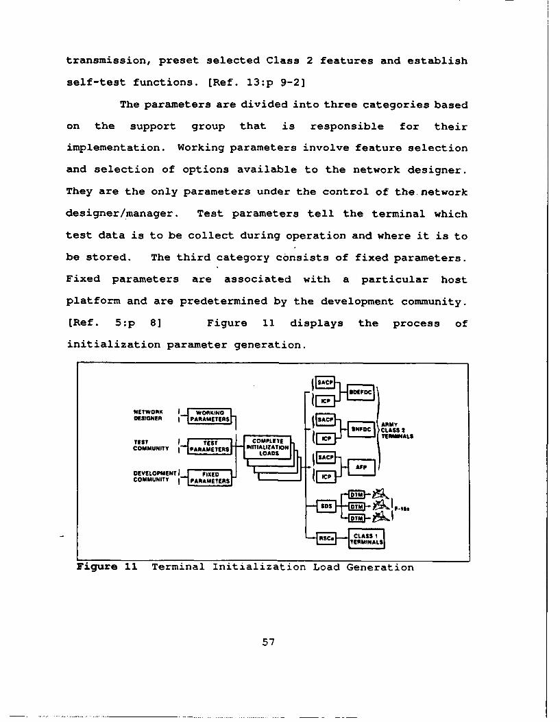
transmission, preset selected Class 2 features and establish
self-test functions. [Ref. 13:p 9-2]
The parameters are divided into three categories based
on the support group that is responsible for their
implementation. Working parameters involve feature selection
and selection of options available to the network designer.
They are the only parameters under the control of the. network
designer/manager. Test parameters tell the terminal which
test data is to be collect during operation and where it is to
be stored. The third category consists of fixed parameters.
Fixed parameters are associated with a particular host
platform and are predetermined by the development community.
(Ref. 5:p 8] Figure 11 displays the process of
initialization parameter generation.
NETWORK TJW-nKINOLDESIGNER 1PARAMETERSn 1ARMY
nlAURMATLNTES I ~J~IS "FCDC CAMYTESTT COMPLETE CTEMNL
COMMUNITY I PARAMETERS ITIALIZATION
DEVELOPMENT I FIXEDCOMMUNITY I PARAMETERS
Figure 11 Terminal Initialization Load Generation
57
Numerous devices are used to load initialization
parameters into each of the terminals. The Stand Alone
Control Panel (SACP) and the Interface Control Panel (ICP) are
used to load the Army's Class 2M terminal. The Software
Development Station (SDS) is used to set initialization
parameters which are loaded into a number of Data Transfer
Modules (DTMs). The DTMs have battery powered memories which
store the designated parameters. Tactical aircraft pilots
carry the DTM to their aircraft and load the parameters into
the aircraft's control panel. The Class 1 terminal is loaded
through operator entries on the Radio Set Control (RSC) panel.
[Ref. 5:p 8-9]
Multiple net operations are now possible with the
introduction of the Class 2 terminal. A great deal of
flexibility in network design has also been achieved, but this
has been accomplished at the cost of greatly increased
complexity of design. The network designer must understand
the information requirements of the users he is supporting.
The designer must also know who must communicate with whom and
what type of information is to be exchanged. Correct network
design choices will ensure all appropriate communication
channels are established.
C. NETWORK DESIGN FOR JTIDS JTAO
A J.'Tn network is designed to support the tactical
communication requirements of the joint air defense system,
58
known as the Joint Tactical Air Operations (JTAO) system. Air
Force command and control elements receive JTIDS service
through Class 1 terminals located in Adaptable Surface
Interface Terminals (ASITs). The ASIT can be deployed
directly to a Command and Reporting Center (CRC) or to a
Message Processing Center (MPC) which services the CRC via a
TADIL B data link. The E-3A AWACS also contains a Class 1
terminal, but the ASIT is not required. The Army C2 portion
of the JTAO is the HAWK Brigade Fire Direction Center
(BDEFDC). These C2 elements employ the Class 2M terminal to
direct accomplishment of the defensive counterair (DCA)
mission. The Air Force CRC is the primary player in joint
tactical air operations. The CRC generates and receives
surveillance data, assigns engagement missions to organic
aircraft, and coordinates with Army HAWK missile elements.
The E-3A aircraft provides surveillance -iiformation and may
act as the CRC when the situation warrants. The BDEFDC
assigns engagement missions to its Assault Fire Platoons
(AFPs) via the Battalion Fire Direction Center (BNFDC) (This
will be discussed in detail in Chapter IV). [Ref. 14]
The JTIDS Main Net, designated as net 0, is the medium for
exchange of surveillance information. Since Air Force C2
elements are equipped with Class 1 terminals, IJMS is the
message format used on the Main Net. Tactical aircraft
monitor the Main Net to establish an air situation picture.
All JTIDS members transmit P messages into the Main Net.
59
Control messages, status reports and assignment
acknowledgements are also exchanged on the Main Net. A subnet
is established for tactical aircraft to exchange organic data
track data and to provide digital voice. [Ref. 13:p 11-2]
Information exchange can occur between tactical aircraft
and Army air defense elements. The TADIL J message format can
now be used because a subnet can be established without Class
1 terminal participants. Use of TADIL J permits the expansion
of multinet operations. [Ref. 13:p 11-7]
D. ARMY NET M2NAGMZINT
1. Means 6f Zuployment
Army development of JTIDS surfaced a unique deployment
difficulty that was not encountered by other services. JTIDS
communication means require line of sight transmission. This
factor was not a significant problem to airborne platforms.
However, ground army air defense units often encounter terrain
that requires precise engineering to ensure a proper signal to
noise ratio (i.e. Europe and Korea). The Army has developed
two automated tools to meet engineering requirements. These
tools will enable network managers to surpass anti-jam
margins, site relays for maximum effectiveness and manage
cryptovariable keys. [Ref. 15]
The Net Control Station JTIDS (NCS-J) was designed to
provide automated net management and technical control. The
NCS-J generates initialization data and cryptovariables for
60
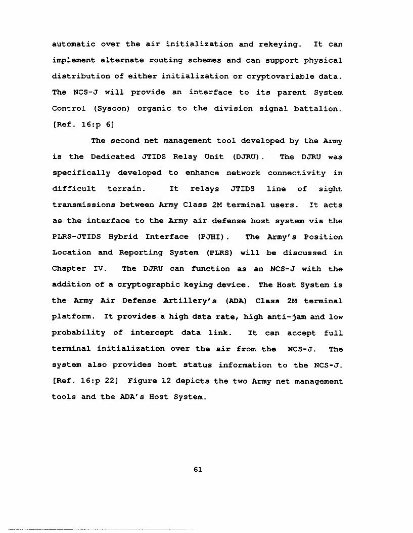
automatic over the air initialization and rekeying. It can
implement alternate routing schemes and can support physical
distribution of either initialization or cryptovariable data.
The NCS-J will provide an interface to its parent System
Control (Syscon) organic to the division signal battalion.
[Ref. 16:p 6]
The second net management tool developed by the Army
is the Dedicated JTIDS Relay Unit (DJRU). The DJRU was
specifically developed to enhance network connectivity in
difficult terrain. It relays JTIDS line of sight
transmissions between Army Class 2M terminal users. It acts
as the interface to the Army air defense host system via the
PLRS-JTIDS Hybrid Interface (PJHI). The Army's Position
Location and Reporting System (PLRS) will be discussed in
Chapter IV. The DJRU can function as an NCS-J with the
addition of a cryptographic keying device. The Host System is
the Army Air Defense Artillery's (ADA) Class 2M terminal
platform. It provides a high data rate, high anti-jam and low
probability of intercept data link. It can accept full
terminal initialization over the air from the NCS-J. The
system also provides host status information to the NCS-J.
[Ref. 16:p 22] Figure 12 depicts the two Army net management
tools and the ADA's Host System.
61
MAJOR COMPONENTS CAPABILIllES
10 ANOINIJA Net Control Staii,,ii J I |LS(NCSI)* Overall sy-oonr control .did
KOnI , itot,.,J of lise JtI1I15comminicatloui system
Nu Provides over-the -air rekeyNCSJ ol cryptovariables0 Provides over-tihe-air•
ACCSl S M " - initialization ol all ii1.1w u k:- ... members
.......... " Verifes receive sig, al
strength on all netwutk trcks" Can assume control over
existing net10 AMlltIA
Dedicated JT IDS Relay Uni IDJRU (OJRU)
0 Enhances networkconnectivity in rugged terrain
CESIvSOM% 1 - a provides remote interlace(up to I kin) to Host Systemvia Pt IIf (X2S)
10 APtIMIIt4A
flost System 41111D$IjjOASYTE Conintrication Portion Only)
tOST SYSTEM - 6 Provides high data rate. high(FAAD) anti-jam and low probability
rruu of intercept data link= Accepts lull initialization
AC - over the nir from NCSI orCs1IDS IM ~locally from ACCS CIIS0 Provides host status
inlormalion 1o the NCSJ
ACRONYMS
Army Command and Control System (ACCS CHISJ
Enhanced PILRS User Unit (EPUU)
Figure 12 Army JTIDS Communication System
62
2. Army JTIDS Network Employment
All of the Army's network design and management of
JTIDS is centered around the NCS-J. The NCS-J develops the
initial network design off line; either while it is in
garrison or prior to its establishment within the net. The
station makes use of preplanned Rapid Load (RL) files to
create an overall mission file. The RL files are organized
under a menu driven database. This database contains a
standard set of initialization parameters for all JTIDS users,
tailored to specific units (i.e. Heavy, Light, Airborne, HIMAD
(HAWK or PATRIOT), etc.). The stored parameters include all
64 initialization blocks which can be updated over the air by
the NCS-J. The NCS-J then validates the employment plan and
resolves any conflicts. Mission unique RL files are generated
and distributed to all network members. [Ref. 13:p 11-9]
The NCS-J's next task is to plan for an area grid
system deployment. A terrain analysis is performed for the
unit's area of operation. Line-of-sight signal path profiles
are made to ensure network connectivity. Precise path
engineering is necessary to guarantee that the anti-jam margin
is met. Once initial locations are determined, the terminals
are deployed throughout the area of operations. [Ref. 13:p
11-10]
Once deployment is accomplished, the NCS-J transmits
initialization parameters to all Class 2M terminals in the
net. It performs link anti-jam margin verifications and
evaluates the results. Links that are determined to be
susceptible to jamming are corrected. The NCS-J continues to
monitor and maintain the network. The station repeatedly
performs network design tasks to redeploy network assets due
to significant changes in the air battle. [Ref. 13:p 11-11]
All NCS-J functions are controlled by the Division
Signal Battalion System Control (Syscon). The Syscon
coordinates with the Air Battle Management Operations Center
(ABMOC) of the Forward Area Air Defense (FAAD) Battalion S-3.
The Division G-3 staff plans the battle based on the
Division Commander's concept of the operation. The Division
G-3 tasks subordinate units as required. The air defense
portion of the battle is tasked through the ADA Liaison
Officer (LNO) to the ABMOC. Communication requirements are
tasked through the Assistant Division Signal Officer (ADSO) to
the Division Signal Battalion. At Corps level and above the
NCS-J and DJRUs are organic assets of the air defense
community and are controlled directly by the ADA. [Ref. 16:p
31] Figure 13 depicts Division JTIDS network management.
64
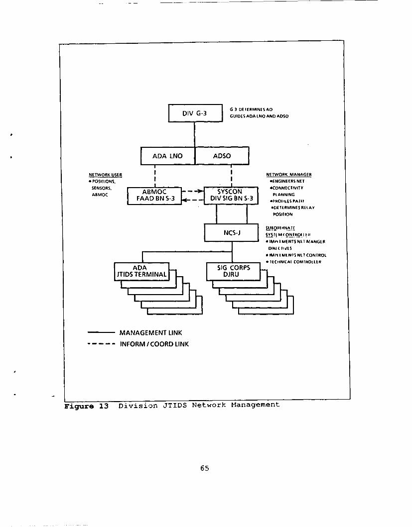
G.3 DEIERMINES AODIV G-3 GUIDES ADA LNO AND ADSO
SADA LNO ADSO
NETWORK USER NETWORK MANAGER
o POSITIONS. I ENGINEERS NET
SENSORS, n|eCONNECTIVITY
ABMOC ABOSSO PLANNINGFAAD BN S-3 DIV SIG BN S-3 014401 ILES PAIII
ODE I ERMINES REL AY
POSIT ION
NCS-J Sy InM( ONjItOI I I"
0 IMPl I MENIS NE I MANGE R
DINI1( IfVL S
* IMII I MINIS NE I CONTROLFI ItCJNIAI CONII4OLtE
MANAGEMENT LINK
INFORM / COORD LINK
Figure 13 Division JTIDS Network Management
65
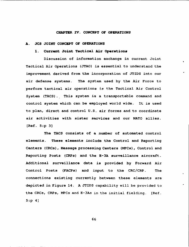
CHAPTER IV. CONCEPT OF OPERATIONS
A. JCS JOINT CONCEPT OF OPERATIONS
1. Current Joint Tactical Air Operations
Discussion of information exchange in current Joint
Tactical Air Operations (JTAO) is essential to understand the
improvement derived from the incorporation of JTIDS into our
air defense systems. The system used by the Air Force to
perform tactical air operations is the Tactical Air Control
System (TACS). This system is a transportable command and
control system which can be employed world wide. It is used
to plan, direct and control U.S. air forces and to coordinate
air activities with sister services and our NATO allies.
[Ref. 5:p 3]
The TACS consists of a number of automated control
elements. These elements include the Control and Reporting
Centers (CRCs), Message processing Centers (MPCs), Control and
Reporting Posts (CRPs) and the E-3A surveillance aircraft.
Additional surveillance data is provided by Forward Air
Control Posts (FACPs) and input to the CRC/CRP. The
connections existing currently between these elements are
depicted in Figure 14. A JTIDS capability will be provided to
the CRCs, CRPs, MPCs and E-3As in the initial fielding. (Ref.
5:p 4]
66
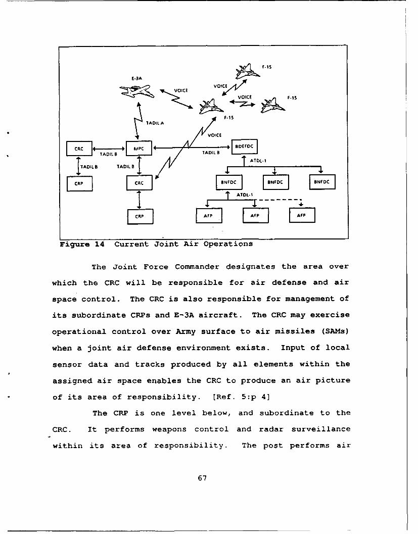
F .15E-3A
' ICE rVOiCE _ F
* FVOICE
* WI ADIL F6 TADI 8 .i1TADIL TADIL B 1.
.AT L ..1
IC" 1 I" IBF-I
Figure 14 Current Joint Air Operations
The Joint Force Commander designates the area over
which the CRC will be responsible for air defense and air
space control. The CRC is also responsible for management of
its subordinate CRPs and E-3A aircraft. The CRC may exercise
operational control over Army surface to air missiles (SAMs)
when a joint air defense environment exists. Input of local
sensor data and tracks produced by all elements within the
assigned air space enables the CRC to produce an air picture
of its area of responsibility. [Ref. 5:p 4]
The CRP is one level below, and subordinate to the
CRC. It performs weapons control and radar surveillance
within its area of responsibility. The post performs air
67
defense and airspace control under the direction of the CRC.
The CRP has the same information processing capability as the
CRC and can assume the responsibilities of the CRC in the
event the CRC is unable to function. [Ref. 4:p 22]
Interface control functions are performed by the MPCs
for all elements within the TACS, Army air defense centers,
intelligence assets and any other elements which require
access to the TACS network. Information exchange between C2
elements is coordinated by the MPC. Data forwarding schemes
are used to direct routing of information among elements which
interface with the TACS. Filters are employed to match the
information flow with the communication capacities of the C2
centers. The MPC can be directed to support Air Force TACC
operations. [Ref. 5:p 4]
The U.S. Air Force E-3A is an airborne C2 platform.
It is subordinate to the CRC. The aircraft provides radar
surveillance and weapons control over a large geographic area,
although its primary delegated control function is
surveillance. It may also perform weapons control as
designated by the CRC. The E-3A can assume the role of the
CRC in the event of its loss. [Ref. 5:p 5]
Army High to Medium Air Defense (HIMAD) consists of
HAWK and Patriot missile systems with their associated
surveillance and command and control elements. The Brigade
Fire Direction Center (BDEFDC), the Battalion Fire Direction
Center (BNFDC) and Assault Fire Platoons (AFPs) are the C2
68
elements for the HAWK system. Track information is exchanged
over Army Tactical Data Links-1 (ATDL-1) between internal
elements. Information is exchanged between HAWK and Air Force
elements, via the BDEFDC, over a TADIL B link to an Air Force
CRC through the appropriate MPC. Patriot brigades utilize
similar command, control and coordination channels. [Ref.
17:p 3]
Actual direction of the air defense battle occurs in
the BNFDC. Functions inherent in the BNFDC are target
detection, target tracking and command and control of firing
units. A BNFDC may function as the BDEFDC in the event that
the BDEFDC is inoperable. Responsibilities assumed by the
BNFDC will include coordination with the Air Force if a joint
operation is in progress. [Ref. 17:p 27]
HAWK AFPs provide radar surveillance and C2 functions
for their organic launch platforms. Maintenance of
communications with its higher headquarters, the BNFDC, is
essential for command and control and track information
exchange. The AFPs also process information from surveillance
data and IFF equipment. [Ref. 17 :p 28]
2. Information Exchange (Non-JTIDS)
The TADIL B digital data link is the primary
communication means between ground C2 elements. Point-to-
point communications are provided for the TADIL B link. An
information processor is located at each C2 element. Each
69
processor contains a number of data ports, with each port
associated with a particular source and destination. Host
processors are capable of forwarding data between elements
lacking a direct TADIL B link. The host is provided with a
list of users that are directly connected to the host via a
particular port. Those units to which data may be passed
indirectly through a forwarding unit are also identified with
a particular port. This routing list is provided to the host
processor during the initialization procedure. [Ref. 5:p 5]
TADIL B data links were developed to exchange
information over point-to-point channels. Tropospheric
scatter radio is a common example of the communications means
utilized to pass this information. The data passed over the
network may be described within the scope of four categories:
a. Track and Track Management
Exchange of surveillance information among C2
elements is the primary function of track management. Track
messages provide location, identification and other pertinent
information on possible airborne targets. A protocol has been
developed that ensures that the best track on any given target
is reported only by that unit having that track. Other units
on the TADIL B network with inferior tracks on the same target
will not transmit their track information. The other units
may determine, at a later period in time, that their track has
become superior. In that event, the unit with the superior
70
track will transmit its information. The superior track
report must propagate through the network link by link because
TADIL B is a point-to-point communications network. Each host
processor compares its local track with the track report
received over its TADIL B links. The best track is selected
and then broadcast over all of the host's TADIL B links except
the one on which the superior track was received. All other
host processors then stop transmitting track reports on the
same target upon receipt of the superior track. Dual track
numbers are assigned by different C2 units to resolve
discrepancies. Track management messages and link protocols
ensure consistent track numbering, reporting unit
identification and position referencing. [Ref. 5:p 6]
b. & Unit Status
All C2 units regularly broadcast unit status
information over the link. Status reports contain information
on the unit's assets (i.e. aircraft), the status of targets
those assets are assigned to engage. Status reports may
contain other information that is relevant to the combat
effectiveness of the unit. [Ref. 5:p 6]
c. C Coordination
Coordination between C2 units is accomplished
through transmission of formatted TADIL B messages. These
messages are designed to enable one C2 unit to direct another
to assign assets against a particular target. These messages
71
can also be used to transfer control of assets between Air
Force C2 units. [Ref. 5:p 6]
d. Special Information Transfer
Message formats are available within the TADIL B
system to provide information to another C2 element regarding
special points of interest or in the event of an emergency.
Intelligence information is also passed in this manner.
The E-3A is not directly involved in the TADIL B
network. It participates in the network via a TADIL A link to
the MPC. The MPC is the interface between the TADIL A and
TADIL B links. The E-3A is thereby able to participate in the
exchange of information across the network. [Ref. 5:p 6]
The BDEFDC participates in the network over a
direct TADIL B link. Subordinate HAWK units communicate with
the BDEFDC via the ATDL-1 link. Information exchange over the
ATDL-1 link is similar to TADIL B. Track handling, multiple
track deconfliction and engagement status are processed in a
manner very similar to TADIL B. The major difference between
the data links is that ATDL-1 is strictly hierarchical. There
is no lateral crosstelling of tracks, handover of assets, or
asset status reporting. There is also no facility to forward
messages because each host processor port is designated for a
single data port. [Ref. 17:p 29]
72
e. SummaZy
It is important to note that currently there is no
digital data link between Air Force fighter aircraft and the
network. The only information exchange that takes place is
accomplished over a voice channel. Voice channels are
established between the pilot and his CRC and/or an E-3A. The
fighter pilot has no need for the majority of information
available over the digital network. A filtered portion of
this information, tailored to the pilot's needs, would greatly
enhance the pilot's air situation picture. Currently,
information on incoming hostiles that have previously been
targeted by friendly SAMs or other fighter formations is not
available. This information could influence the flight
leader's target assignments.
The fighter control function is accomplished solely
by voice communications. Mission assignment, engagement
status, mission results and aircraft status are all
communicated over a voice channel. Handovers between C2 units
in which fighters participate and surveillance information
passed to the pilot are also accomplished over a voice link.
Critical information may not be available to the fighter pilot
when it is needed. [Ref. 5:p 7]
3. JTIDS Equipped Joint Tactical Air Operations
JTIDS can be incorporated into the JTAO environment as
a one for one replacement for existing digital data links.
73
This concept is extremely limited and does not utilize the
full potential of a JTIDS communications network. JTIDS is
capable of much more than copying a simple point-to-point data
communications network. A fundamental principle of JTIDS is
that any terminal is capable of communicating with any other
terminal or group of terminals.
Some restrictions are inherently embeded in the system
such as terminal capacity and limitations due to line-of-sight
requirements. The line-of- sight limitation can be overcome
by placement of relays at proper positions throughout the
network. Figure 15 contains a representation of the JTIDS
Concept of Operations. [Ref. 18:p 13]
JTIDS service is provided to the CRC by connecting an
Adaptable Surface Interface Terminal (ASIT), with a Class 1
terminal, to the CRC. A translator processor within the ASIT
provides the interface between the Class 1 terminal and the
CRC. This interface appears to the CRC as a TADIL B link.
JTIDS is therefore transparent to the CRC which continues to
process TADIL B information. The Class 1 terminal transmits
CRC messages into a Main Net which includes all Class 1
terminals. The CRC messages may then be received by all JTIDS
terminals in the net, to include tactical aircraft.
Surveillance information can then be exchanged in a common
pool. Additionally, each JTIDS terminal will broadcast to the
net P messages which provide position, identification and
sta.us of the host platform. The ASIT converts the P messages
74
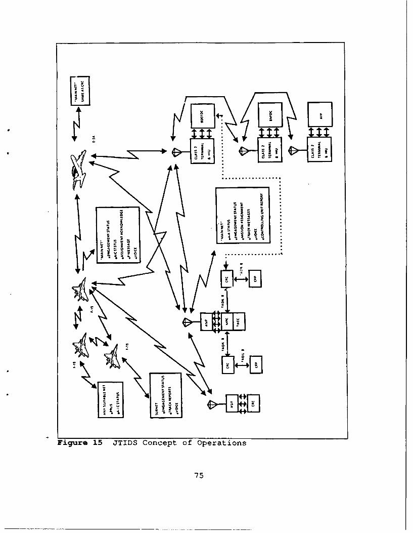
LI M
FI
Fiur 15 J D Cocp o prain
- 4 -p.-
into TADIL B track reports for use by the CRC. Status, C2
coordination and other categories of TADIL B information are
broadcast on the Class 1 Main Net. Class 2 terminals can
translate IJMS messages available on the Class 1 Main Net
since they are bilingual. A direct digital data link between
the CRC and E-3A over the Main Net replaces the TADIL A link
via the MPC. Finally, CRC command instructions can be made,
through the cockpit display, to tactical aircraft. [Ref. l:p
87-132]
The interservice connection between the CRC and the
BDEFDC is also replaced by JTIDS. The BDEFDC, using a Class
2M terminal, is a full participant in the Main Net. It must
therefore listen to all potential track sources as each source
will transmit only superior tracks. This will result in an
air situation picture that contains only superior tracks.
Links between the BDEFDC, BNFDC and AFPs will also be over
JTIDS. ATDL-l messages are embedded in JTIDS message
transmissions. The Host Interface Unit (HIU), which acts in
the same manner as the ASIT, makes JTIDS transparent to Army
air defense host processors. [Ref. 5:p 7]
There are two new features which are added under the
JTIDS network. First, high quality position, status and
identification information, formatted as Precise Position
Location Identification (PPLI) messages, can be directly
received from tactical aircraft by the BDEFDC and Master
BNFDCs. Autonomous AFPs are also capable of receiving this
76
information directly when they are not receiving data from
their parent BNFDC. These PPLI messages transmitted by
tactical aircraft will be in addition to the standard IJMS P
messages the aircraft regularly transmit into the Main Net.
Both message types will add tc the air situation picture.
This view of the air battle is filtered to meet individual
requirements of Army air defense units. [Ref. 13:p 5-13]
The second feature JTIDS adds to the HIMAD mission is
that all tactical aircraft in the net will directly receive
AFP engagement status. Pilots will immediately be aware of
hostile tracks that have been previously targeted by friendly
ground air defense assets. The flight leader can then assign
his aircraft to targets not previously engaged. [Ref. 18:p
22]
The role the E-3A plays in the air battle is
essentially unchanged, with one notable exception. The E-3A
directly communicates with all net members. It no longer
transmits and receives information via the MPC. Tactical
aircraft position, status and identification information is
directly available to the E-3A. The E-3A can also directly
transmit mission assignments to the aircraft under its
control. Mission assignments are presented on the tactical
aircraft cockpit display. Acknowledgement of receipt will
then be transmitted directly to the E-3A. Due to line of
sight communications limitations, the E-3A's unique position
77
allows it to function as a communication relay for all JTIDS
participants. [Ref. l:p 89]
JTIDS provides tactical aircraft with a number of
greatly enhanced capabilities:
a. Position and Status Reporting
Tactical aircraft will transmit their position and
status under both the IJMS and TADIL J message format. The
Main Net contains those platforms which are equipped with
Class 1 terminals (i.e. CRC and E-3A). Tactical aircraft
transmit IJMS P messages once every 12 seconds to update the
Main Net. Airborne radar track data are exchanged among
tactical aircraft, as well as position, status and
identification. TADIL J PPLI reports are therefore transmitted
once every 3 seconds to aircraft in the net equipped with
Class 2 terminals. [Ref. ':p 55]
b. Surveillance
Currently, tactical aircraft have only their
onboard radar as a source of tracks. All other track
information that is available from ground C2 units can only be
transmitted over a voice channel. Equipped with the JTIDS
Class 2 terminal, the pilot can select track information from
the Main Net, the air group's subnet or a combination of the
two nets. The number of potential targets can be limited by
the pilot selecting a specific set of criteria. These
78
criteria may include track source or target range divided by
range rate. [Ref. 5 :p 7]
c. Target Selection and Coordination
C2 elements transmit mission assignments to
assigned aircraft. This information will be represented on
the pilot's cockpit display. The pilot WILCOs the assignment
and the target is displayed as engaged. An engagement status
report is then transmitted into both the Main Net and the air
group's subnet. The situation may warrant the flight leader
assigning targets to aircraft without the direction of C2
elements. In this event, engagement status is transmitted
over both the IJMS Main Net and the TADIL J air group subnet.
Radar lock-on by individual tactical aircraft is also
transmitted in both message formats and presented on the
cockpit displays of all JTIDS participants. [Ref. 5:p 7]
d. Navigation
Tactical aircraft that are equipped with JTIDS may
update their inertial navigation system. The terminal
performs this update based on ranging to ground stations whose
position are precisely known. (Ref. 5:p 7]
o. Digital Voice
One final capability available to most JTIDS users
is digital voice. Only the Army's Class 2M terminal lacks
this capability. JTIDS provided digital voice will serve as
a backup to current voice communications means. Digital voice
79

will be implemented on the Class 1 Main Net. Tactical
aircraft pilots will have the option to select digital voice
on a subnet unique to that pilots air group. Use of digital
voice on a subnet eliminates participation on the voice
portion of the Main Net. [Ref. 13:p 8-21]
B. ARMY CONCEPT OF OPERATIONS
1. Introduction
Technical innovations have drastically altered the
conduct of war. Today's weapon systems are increasingly more
sophisticated and lethal. The tactics employed by the various
military services have been forcibly changed due to technical
advances. Tactics that are designed to complement these
weapon systems ensure a reasonable chance of success on the
modern battlefield. Effective command, control, and
communications (C3) is essential to efficiently employ modern
tactics. The United States Army develcped FM 100-5, the
Operations Field Manual, to establish doctrine based on
current tactics.
FM 100-5 is the cornerstone of Airland Battle doctrinalliterature on how the Army forces plan to conductwarfighting operations. It furnishes the authoritativefoundation for subordinate doctrine, force design,material acquisition, professional education, andindividual and unit training. [Ref. 19:p i]
2. Airland Battle Doctrine
Airland battle doctrine states that a qualitatively
superior force can defeat a quantitatively superior force.
80
This doctrine, first published in 1982, incorporated many
intangibles of war such as leadership, training, and surprise.
Airland battle doctrine returns to more offensive operations
and incorporates new views.
The first doctrinal concept is the deep battle which
implies that fighting in the enemy's rear area will slow his
forces and disrupt follow-on echelon forces. The second
concept focuses on the importance of individual initiative in
battle. The third concept highlights decentralization of C3,
which enables combat commanders to seize and maintain the
initiative. The fourth concept emphasizes maneuver to
increase effective firepower. The fifth concept is the
addition of the operational level of combat between the
tactical and strategic levels. Finally, The last major
concept places a much greater emphasis on combined and joint
operations. (Ref. 19:p 179]
FM 100-5 was updated in 1986 to place a lesser
emphasis on NATO and provide a more general view of combat
around the world. The goal of the 1986 version is to prepare
U.S. forces to fight in a full spectrum of scenarios. Central
to this version are the four Airland battle tenants.
The basic tenants of Airland Battle doctrine - initiative,agility, depth and synchronization are reemphasized.Initiative means to set or change the terms of battle byaction. Agility is the ability of friendly forces to actfaster than the enemy. Depth is the extension ofoperations in space, time, and resources. Synchronizationis the arrangement of battlefield activities in time,space, and purpose to produce maximum relative combatpower at the decisive point. [Ref. 19 :p 14-18]
81
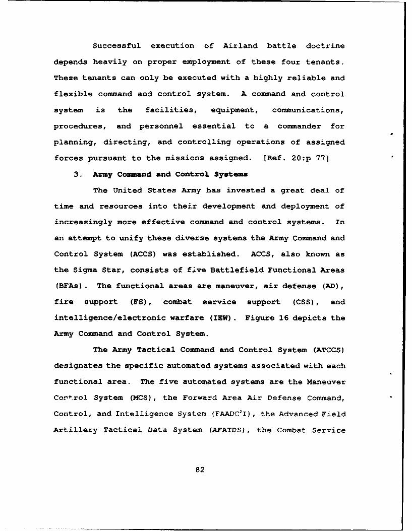
Successful execution of Airland battle doctrine
depends heavily on proper employment of these four tenants.
These tenants can only be executed with a highly reliable and
flexible command and control system. A command and control
system is the facilities, equipment, communications,
procedures, and personnel essential to a commander for
planning, directing, and controlling operations of assigned
forces pursuant to the missions assigned. [Ref. 20:p 77]
3. Army Command and Control Systems
The United States Army has invested a great deal of
time and resources into their development and deployment of
increasingly more effective command and control systems. In
an attempt to unify these diverse systems the Army Command and
Control System (ACCS) was established. ACCS, also known as
the Sigma Star, consists of five Battlefield Functional Areas
(BFAs). The functional areas are maneuver, air defense (AD),
fire support (FS), combat service support (CSS), and
intelligence/electronic warfare (IEW). Figure 16 depicts the
Army Command and Control System.
The Army Tactical Command and Control System (ATCCS)
designates the specific automated systems associated with each
functional area. The five automated systems are the Maneuver
Control System (MCS), the Forward Area Air Defense Command,
Control, and Intelligence System (FAADC2I), the Advanced Field
Artillery Tactical Data System (AFATDS), the Combat Service
82
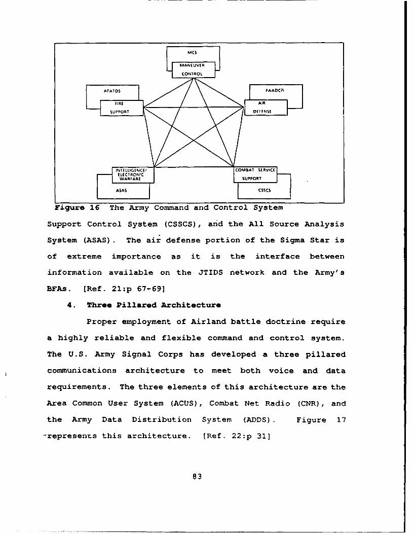
MC$
MANEUVER
CONIROL
SUPPORT D~rFNSF
WARFARE SUPPORT
ASAS -1L CS$C$
Figure 16 The Army Command and Control System
Support Control System (CSSCS), and the All Source Analysis
System (ASAS). The air defense portion of the Sigma Star is
of extreme importance as it is the interface between
information available on the JTIDS network and the Army's
BFAs. [Ref. 21:p 67-69]
4. Three Pillared Architecture
Proper employment of Airland battle doctrine require
a highly reliable and flexible command and control system.
The U.S. Army Signal Corps has developed a three pillared
communications architecture to meet both voice and data
requirements. The three elements of this architecture are the
Area Common User System (ACUS), Combat Net Radio (CNR), and
the Army Data Distribution System (ADDS). Figure 17
-represents this architecture. [Ref. 22:p 31]
83
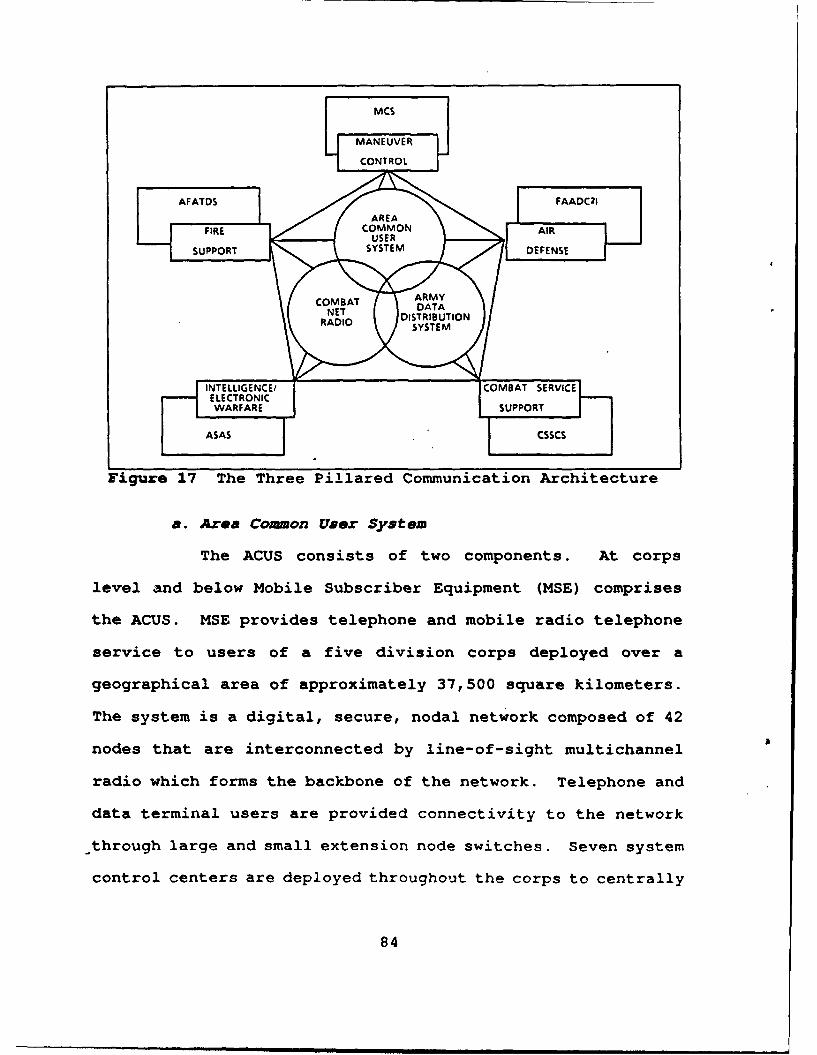
IMCS
MANEUVER
CONTROL
FIRE COM M O N AIR- -SUPPORT SYSTEM DEFENSE
COMBAT ARMYDISTRIBUTION
RADIO SYSTEM
INTELLIGENCE/
COMBAT SERVaICEELECTRONIC
ASAS CSSCS
Figure 17 The Three Pillared Communication Architecture
a. Area Common User System
The ACUS consists of two components. At corps
level and below Mobile Subscriber Equipment (MSE) comprises
the ACUS. MSE provides telephone and mobile radio telephone
service to users of a five division corps deployed over a
geographical area of approximately 37,500 square kilometers.
The system is a digital, secure, nodal network composed of 42
nodes that are interconnected by line-of-sight multichannel
radio which forms the backbone of the network. Telephone and
data terminal users are provided connectivity to the network
through large and small extension node switches. Seven system
control centers are deployed throughout the corps to centrally
84
manage the network. [Ref. 23:p 8-14] A recent technical
insertion program has upgraded the system to a packet
switched network following X.25 protocol. MSE is
interoperable with combat net radios such as SINCGARS through
its radio net interface. It is also interoperab~e with
satellite terminals and can be linked with NAoTO analog,
digital, and facsimile equipment. [Ref. 24:p 42]
The Echelons Above Corps Communications Improvement
Program (EAC CIP) is the second component of the ACUS. The
EAC CIP provides both voice and data communications to Army
echelons above the corps level. The system provides an
integrated theater area communications system by overlapping
mobile subscriber capabilities on the existing EAC common user
digital network. The system was originally designed according
to the tri-service tactical communications (TRI-TAC) Block II
architecture. The EAC CIP provides expanded service via an
increased number of circuit switching nodes. Communications
support to theater army command headquarters has been
streamlined. Designated EAC users will receive mobile
subscriber service. [Ref. 25:p 17]
b. Combat Net Radio
CNR consists of the Single Channel Ground and
Airborne Radio System (SINCGARS) and the Improved High
Frequency Radio (IHER). SINCGARS is a frequency hopping radio
system designed to provide secure voice and data
85
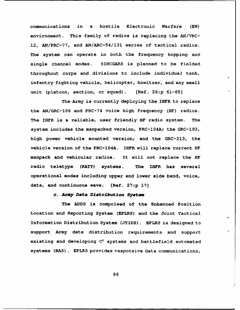
communications in a hostile Electronic Warfare (EW)
environment. This family of radios is replacing the AN/VRC-
12, AN/PRC-77, and AN/ARC-54/131 series of tactical radios.
The system can operate in both the frequency hopping and
single channel modes. SINCGARS is planned to be fielded
throughout corps and divisions to include individual tank,
infantry fighting vehicle, helicopter, howitzer, and any small
unit (platoon, section, or squad). [Ref. 2 6:p 61-65]
The Army is currently deploying the IHFR to replace
the AN/GRC-106 and PRC-74 voice high frequency (HF) radios.
The IHFR is a reliable, user friendly HF radio system. The
system includes the manpacked version, PRC-104A; the GRC-193,
high power vehicle mounted version; and the GRC-213, the
vehicle version of the PRC-104A. IHFR will replace current HF
manpack and vehicular radios. It will not replace the HF
radio teletype (RATT) systems. The IHFR has several
operational modes including upper and lower side band, voice,
data, and continuous wave. [Ref. 27:p 17]
c. Army Data Diatribution System
The ADDS is comprised of the Enhanced Position
Location and Reporting System (EPLRS) and the Joint Tactical
Information Distribution System (JTIDS). EPLRS is designed to
support Army data distribution requirements and support
existing and developing C2 systems and battlefield automated
systems (BAS). EPLRS provides responsive data communications,
86
accurate position, navigation, and identification on the
Airland battlefield.
The principal components of the system are the
Enhanced PLRS Terminal (PT) and the Net Control Station (NCS).
The PT consists of an Enhanced PLRS User Unit (EPUU), a User
Readout (URO) device or a Pilot Control and Display Panel
(PCDP). The EPUU can support host systems via an X.25
interface or by a Frequency Shift Keying Interface. The
terminal can support a data rate of 1200 bps. The URO device
is for handheld use with the manpack, vehicular, or ground
relay PT. Requests are manually entered on the URO for
position and identification purposes and to send free text
messages. The PCDP, airborne configuration, is designed for
remote operation of the EPUU by the pilot. It is connected to
the aircraft instrument system providing bearing and altitude
information. (Ref. 28:p 1-0]
Under the control of the NCS, the PT provides a
position and navigation service and a limited free text
capability. Interface configurations permit data exchange with
many BASs. The system can be configured in either a manpack,
vehicular, or airborne version. Each NCS controls 150-250
PTs, or approximately a brigade size deployment. Four NCSs
are assigned to a division and fall under the control of the
Division Signal Battalion Syscon. [Ref. 2 9 :p 30] Figure 18
depicts the projected deployment of Army communication
systems.
87
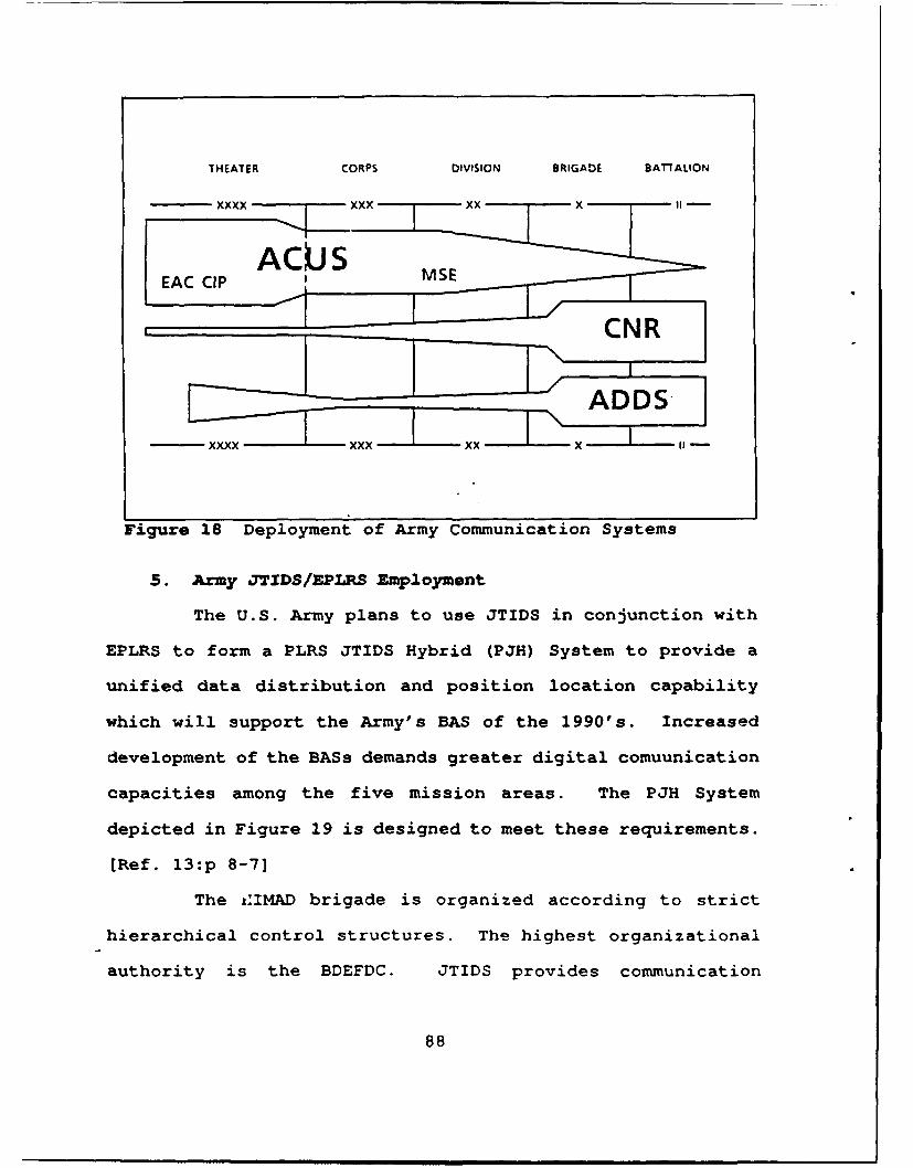
THEATER CORPS DIVISION BRIGADE BATTALION
xxxx - xxx xx "
ACUS
CNR
xxxx xxx xxx
Figure 18 Deployment of Army Communication Systems
5. Army JTIDS/EPLRS Employment
The U.S. Army plans to use JTIDS in conjunction with
EPLRS to form a PLRS JTIDS Hybrid (PJH) System to provide a
unified data distribution and position location capability
which will support the Army's BAS of the 1990's. Increased
development of the BASs demands greater digital comuunication
capacities among the five mission areas. The PJH System
depicted in Figure 19 is designed to meet these requirements.
(Ref. 13 :p 8-7]
The t1IMAD brigade is organized according to strict
hierarchical control structures. The highest organizational
authority is the BDEFDC. JTIDS provides communication
88
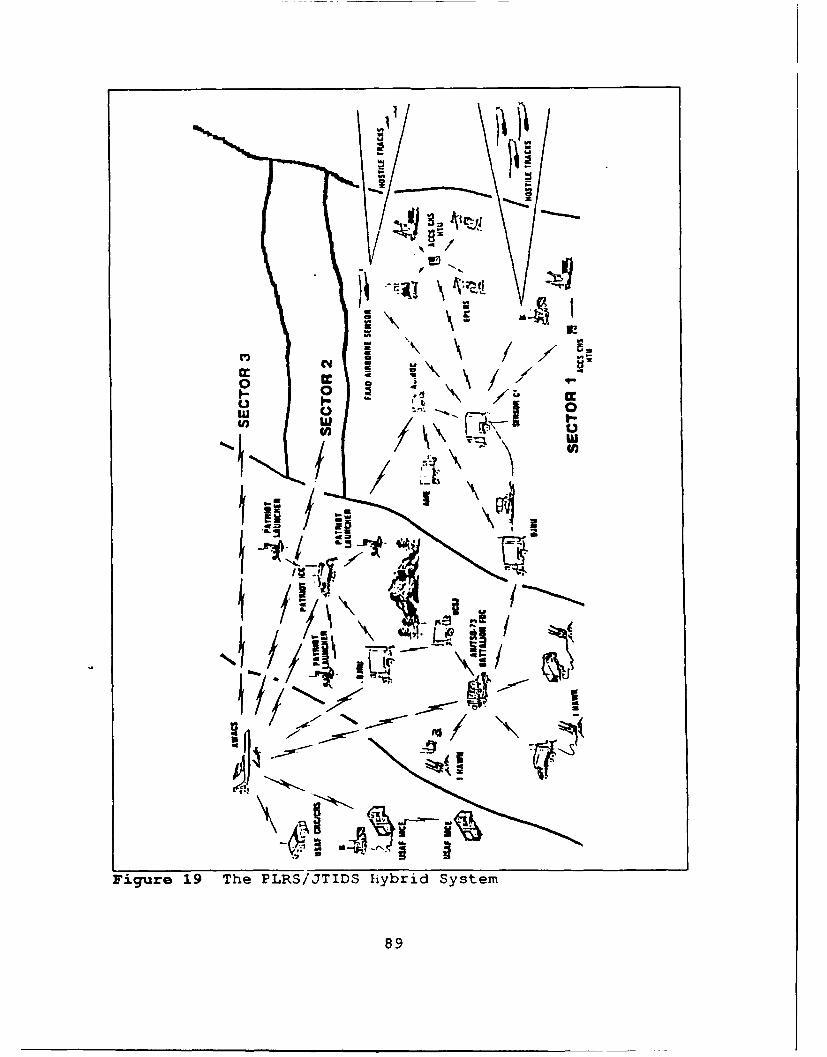
10 .. 9 cc- \ {
11/: yo.,Is
, ]-....Id
IU 0
Uw 4
Figure 19 The PLRS/JTIDS ybrid System
89
circ t , between the HIMAD units and between tne BDEFDC and
the C2 elements of other services.
The Army Class 2M terminal and the Host Interface Unit
(HIU) is the primary JTIDS interface to the HIMAD units. The
HIU communicates with a host terminal via TADIL B or ATDL-1.
The AN/TSQ-73 Missile Minder is the host system at the BDEFDC
and the BNFDC. The HAWK Missile System is the host system at
the AFP. The HIU has the capability to translate fixed format
TADIL J messages into TADIL B and vice versa. The data that
is provide passes to the host system via a single TADIL B
channel. The HIU can also embed ATDL-I messages into TADIL J
Variable Message Format (VMF) messages and extract ATDL-1
messages from TADIL J VMF messages. Precise Participant
Location and Identification (PPLI) messages form JTIDS
equipped airborne platforms are translated into ATDL-l
messages for Army air defense elements. The HAWK HIU will
translate PPLI messages only when operating autonomously;
normally translation is performed at the controlling BNFDC.
Embedding ATDL-l messages into TADIL J VMF messages allows
Class 2M equipped platforms to communicate beyond line-of-
sight through a Class 1 terminal acting as a relay. [Ref. 5:p
38]
90

CHAPTER V. PROPOSED APPLICATIONS FOR JTIDS INFORMATION
DISTRIBUTION
A. INTRODUCTION
The U.S. Army's view of modern warfare has changed
somewhat since the conceptualization of Airland battle. The
Army recognizes the need for the capacity to respond to a
broad spectrum of conflict. This spectrum ranges from Low
Intensity Conflict (LIC) through Mid and High Intensity
Conflict (MIC/HIC), anywhere in the world. The pace of
warfare has also dramatically increased, requiring commanders
to be able to assess current battlefield information and act
accordingly. This directly implies the introduction and
integration of automated tools into all Battlefield Functional
Areas (BFAs). This chapter will discuss potenetial
applications for distribution of JTIDS provided information.
B. AIRLAND BATTLE - FUTURE
1. Projected Doctrine
The Airland Battle-Future (ALB-F) study was produced
by the Combined Arms Center at Ft. Leavenworth, Kansas under
the direction of the Training and Doctrine (TRADOC) Commander.
The purpose of this study was to transition the 1986 Airland
battle doctrine to better prepare the Army to fight future
wars. The objective was to move the Army towards a more
91
strategic projection orientation. The study focused on the
total Army over the next 5 - 15 years. Joint and combined
operations at the tactical and operational level were reviewed
with a less NATO and more global perspective. The TRADOC
Commander's generic guidance to the CAC was three-fold.
First, combat support and combat service support elements
would be moved from the division level to either maneuver
brigades or the corps level. The division would become a
tactical headquarters only. Second, the Army would fight on
a non-linear battlefield, where traditional unit boundaries
become obscure. The Army will fight with fewer soldiers and
smarter, more lethal weapons. Third, that military power is
to be projected from the Continental United States (CONUS)
contingency based force rather than from a forward deployed
presence. (Ref. 30:p 3]
The CAC study developed the concept of operation for
ALB-F. ALB-F can be summarized into four phases. The first
phase consists of intelligence and battle preparation. The
Army's prediction is that modern surveillance devices will
enable commanders to know, with a high degree of certainty,
the location of significant enemy forces at any point in time.
The second phase is the establishment of conditions for
decisive operations. The purpose of this phase is to attrit
the enemy with long range smart/brilliant weapons. The third
phase is decisive operations. Army units will maneuver with
highly agile and lethal forces to quickly destroy the enemy.
92
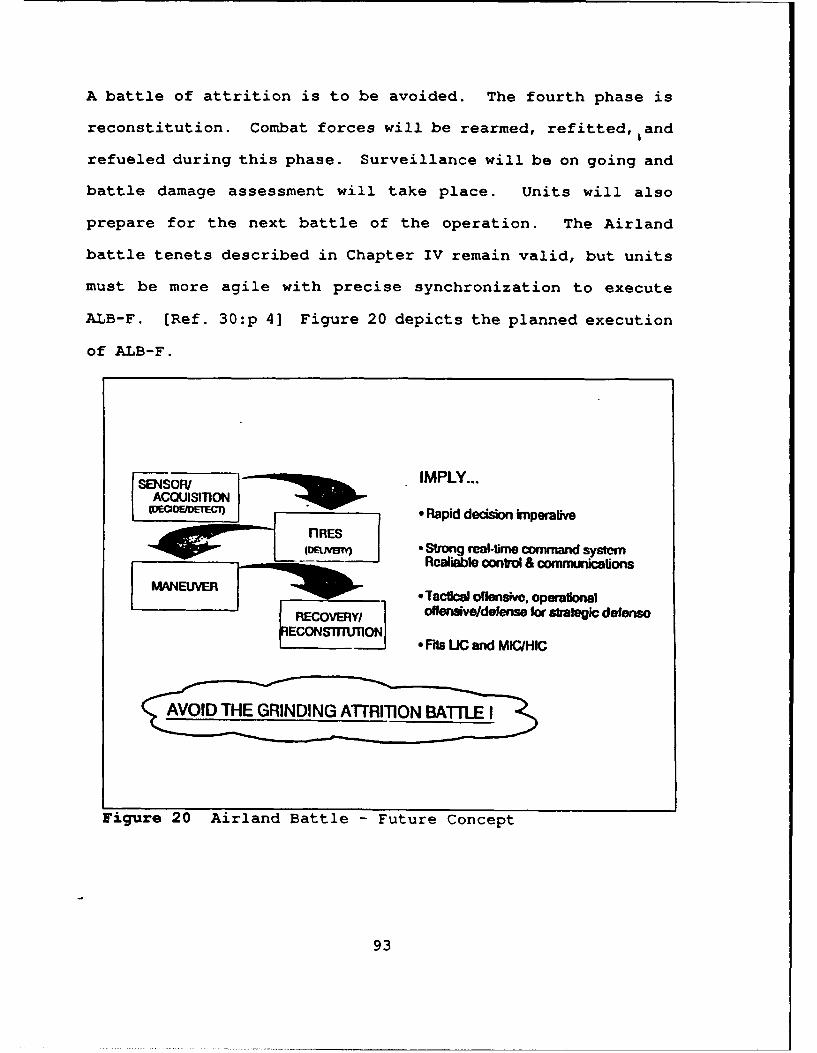
A battle of attrition is to be avoided. The fourth phase is
reconstitution. Combat forces will be rearmed, refitted, iand
refueled during this phase. Surveillance will be on going and
battle damage assessment will take place. Units will also
prepare for the next battle of the operation. The Airland
battle tenets described in Chapter IV remain valid, but units
must be more agile with precise synchronization to execute
ALB-F. [Ref. 30:p 4] Figure 20 depicts the planned execution
of ALB-F.
SMSOR/IMPLY...ACQUISITON -(DOEJIDDETEGJ) * Rapid decision knperaive
nRES
(ONMa~l • Strong real-time command systemRealiable control & commuircations
tM&EUVER 0 Tactica offensive, operationalRCR offensive/defense for strategic defenso
nECONSTmUnON" * Ffis UC and MIC/HIC
Figure 20 Airland Battle - Future Concept
93
2. Communications Support
ALB-F, in order to be successfully accomplished,
implies a number of tasks that must be completed. The U.S.
Army Signal Corps is tasked to integrate sensors, weapons,
commanders, forces, sustainment, and transportation elements.
The Signal Corps must provide and manage a network which will
tie these elements together and be transparent to the user.
Effective command and control is essential to ALB-F.
Integrated, automated systems must be provided to commanders
and staffs to produce a common picture of the battle. The
non-linear battlefield, where unit boundaries are blurred,
will require dispersed communication networks. The range of
communications must be extended to link these dispersed
elements on the battlefield. Under the Airland battle
concept, communicators support users on a linear battlefield.
This system was adequate in its support of heavy forces in
central Europe providing grid-area coverage on a mobile
battlefield. The system's enhanced C2 capabilities offer a
redundant, robust, and survivable network with an increased
data capacity. Communications support on the non-linear
battlefield must support low to high intensity conflicts over
a dispersed battlefield. Extension of the range of
communications will increase the systems flexibility.
Strategic and tactical communication assets will be relied
upon to help increase range. The focus of the communicator
94
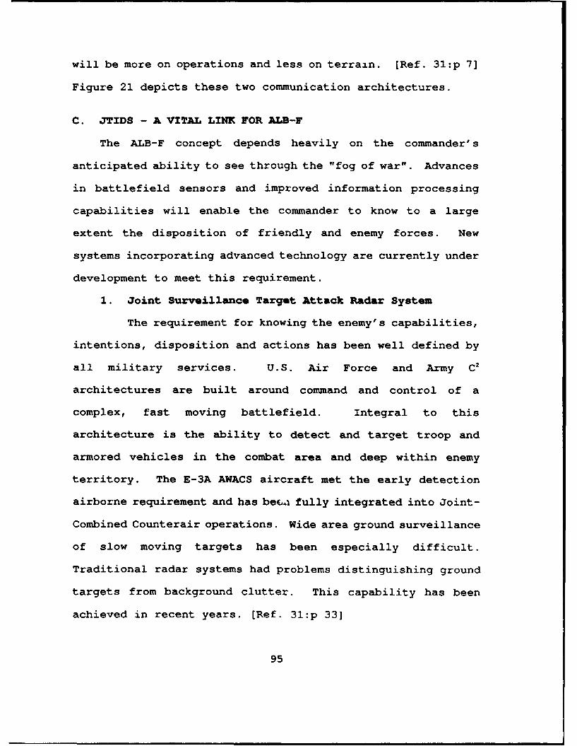
will be more on operations and less on terrain. [Ref. 31:p 7]
Figure 21 depicts these two communication architectures.
C. JTIDS - A VITAL LINK FOR ALB-F
The ALB-F concept depends heavily on the commander's
anticipated ability to see through the "fog of war". Advances
in battlefield sensors and improved information processing
capabilities will enable the commander to know to a large
extent the disposition of friendly and enemy forces. New
systems incorporating advanced technology are currently under
development to meet this requirement.
1. Joint Surveillance Target Attack Radar System
The requirement for knowing the enemy's capabilities,
intentions, disposition and actions has been well defined by
all military services. U.S. Air Force and Army C2
architectures are built around command and control of a
complex, fast moving battlefield. Integral to this
architecture is the ability to detect and target troop and
armored vehicles in the combat area and deep within enemy
territory. The E-3A AWACS aircraft met the early detection
airborne requirement and has beca fully integrated into Joint-
Combined Counterair operations. Wide area ground surveillance
of slow moving targets has been especially difficult.
Traditional radar systems had problems distinguishing ground
targets from background clutter. This capability has been
achieved in recent years. [Ref. 31:p 33]
95
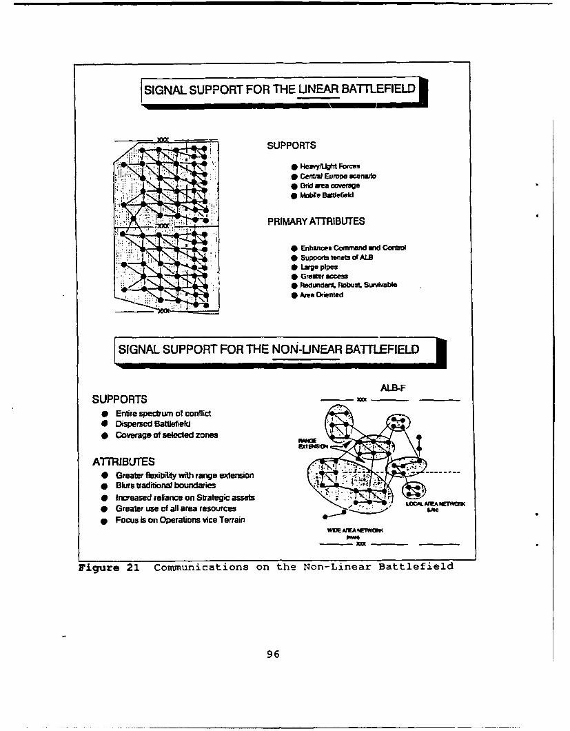
SIGNAL SUPPORT FOR TH-E LINEAR BATLFIEL
:q SUPPORTS
I * Hevyfigtd Forces* Central Europe scenario* Grid area coverage* Mole Bgewid
....... PRIMARY A1TRIBJTES
* Enhances Commnd mid Control* Supportsteesof ALB0 Lage pipes0 Greater acs* Pedundant. PHobust. Survivable* Area Orinted
(SIGNAL SUPPORT FOR THE NON-LINEAR BATLEILE
AL.B-FSUPPORTS __ 3_
0 Entire spectrum of conflict0 Dispersed Battlefield* Coverage of selected zones
ATTRIBL)TES* Greater flexibility with range extension-* Blurs traditional boundaries;0 Increased reian~ce on strategic assets* Greater use of all area resources* Focus is on Operations vice Terrain
WWE MEA NETWORK
Figure 21 Communications on the Non-Linear Battlefield
96
Advances in radar technology and information
processing have made ground battlefield surveillance possible.
The Joint Surveillance Target Attack Radar System (JSTARS) is
an airborne and ground based system with the ability to
identify and track aircraft, missiles, artillery, and maneuver
forces in all weather conditions. JSTARS' primary mission is
to detect non-emitting mobile targets. Priority is given to
those enemy forces in imminent contact with friendly ground
elements. The system simultaneously covers enemy second
echelon forces permitting those elements to be targeted and
destroyed. [Ref. 32:p 33] Figure 22 depicts the JSTARS radar
system.
The U.S. Air Force Electronic Systems Command and the
U.S. Army Communications-Electronics Command are developing a
multinode radar for the E-8A (a modified Boeing 707) aircraft.
Radar surveillance data will be processed on board the
aircraft. Radar display and control capabilities will be
available on board and to ground based C2 elements.
Surveillance data is further processed on board the aircraft
by Operations and Control (O&C) Air Force personnel and by
Ground Station Modules (GSMs). The GSMs communicate to the
radar via a surveillance and control data link. The data is
evaluated by Air Force surveillance operators and weapon
controllers and passed as track data, under the TADIL J
message format, to Air Force C2 elements. GSMs are planned to
be deployed to Army division and corps levels providing input
97
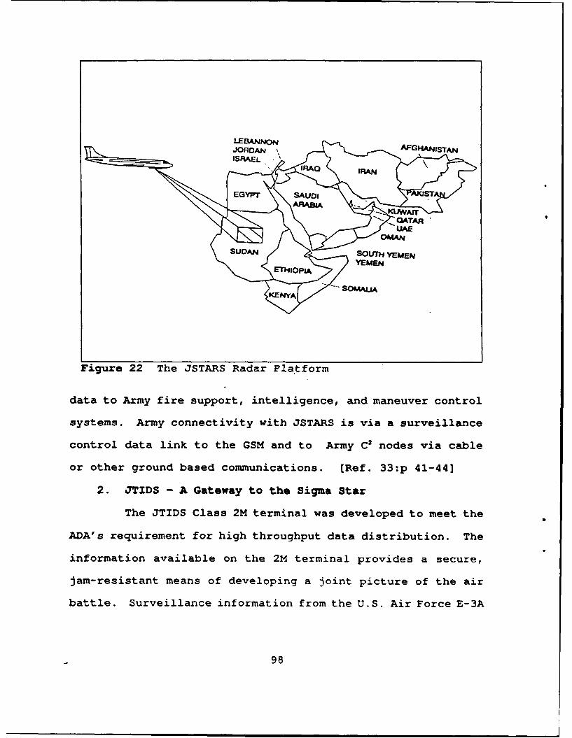
LEBMNN~JORDAN ,AFGHNISTrAN
ISRAEL,
EGYPT SAD
SUDAN SOUT)H YEMEN
YEMENETHIOPIA
Figure 22 The JSTARS Radar Platform
data to Army fire support, intelligence, and maneuver control
systems. Army connectivity with JSTARS is via a surveillance
control data link to the GSM and to Army C2 nodes via cable
or other ground based communications. [Ref. 33:p 41-44]
2. JTIDS - A Gateway to the Sigma Star
The JTIDS Class 2M terminal was developed to meet the
ADA's requirement for high throughput data distribution. The
information available on the 2M terminal provides a secure,
jam-resistant means of developing a joint picture of the air
battle. Surveillance information from the U.S. Air Force E-3A
98
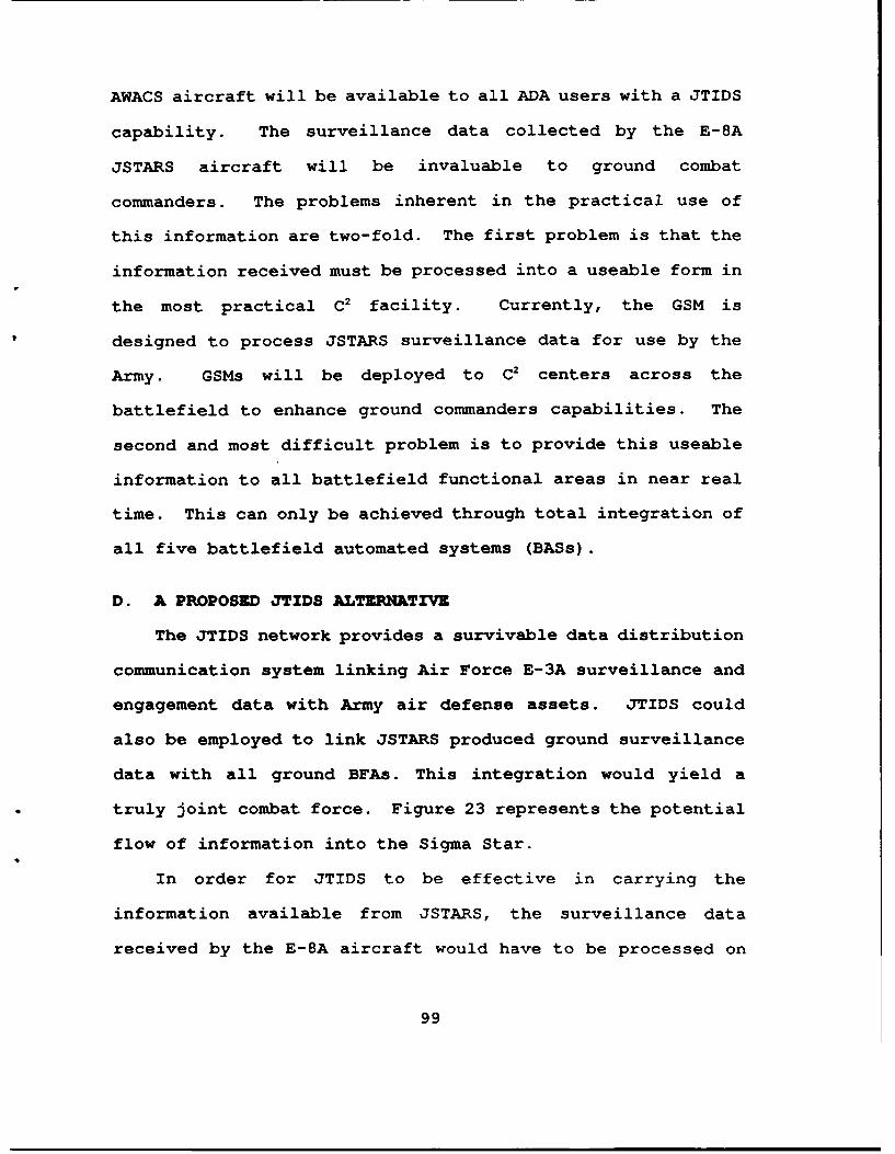
AWACS aircraft will be available to all ADA users with a JTIDS
capability. The surveillance data collected by the E-8A
JSTARS aircraft will be invaluable to ground combat
commanders. The problems inherent in the practical use of
this information are two-fold. The first problem is that the
information received must be processed into a useable form in
the most practical C2 facility. Currently, the GSM is
designed to process JSTARS surveillance data for use by the
Army. GSMs will be deployed to C2 centers across the
battlefield to enhance ground commanders capabilities. The
second and most difficult problem is to provide this useable
information to all battlefield functional areas in near real
time. This can only be achieved through total integration of
all five battlefield automated systems (BASs).
D. A PROPOSED JTIDS ALTERNATIVZ
The JTIDS network provides a survivable data distribution
communication system linking Air Force E-3A surveillance and
engagement data with Army air defense assets. JTIDS could
also be employed to link JSTARS produced ground surveillance
data with all ground BFAs. This integration would yield a
truly joint combat force. Figure 23 represents the potential
flow of information into the Sigma Star.
In order for JTIDS to be effective in carrying the
information available from JSTARS, the surveillance data
received by the E-8A aircraft would have to be processed on
99
JTIDSNE.. WORK
JSTARS AWACS
JTIDS
2M TERMINAL
ADDS
CHS-1TCU
I X.25
MSE OVERLAYOR DDN
OR COMMERCIAL X 25
Figure 23 The JTIDS Alternative
board the aircraft prior to transmission. Army intelligence
analysts would have to be assigned to the JSTARS platform to
insure that the surveillance data is processed in a manner
that is most useful to Army C2 elements. This processed
surveillance information could then be transmitted over a
JTIDS network as the AWACS information is currently
transmitted. Army Class 2M terminals would then act as
gateways to the Area Common User System (ACUS).
100
The Army's product improvement program is providing a
packet switch capability to the MSE portion of the ACUS. It is
anticipated that packet switching will also be provided to EAC
communications. Once this is accomplished, the information
available on JTIDS can be transferred to all functional areas
of the ATCCS. JTIDS furnished information presents a wide
range of potential applications to Army users. [Ref. 25:p 15]
1. Maneuver Control
The near real time picture of enemy ground
dispositions would be invaluable to maneuver commanders. The
Maneuver Control System (MCS) currently enables commanders to
monitor the dispositions of friendly forces in a given theater
of operations. JSTARS surveillance data of enemy positions
would have to be made compatible with the MCS Tactical
Computer Terminal (TCT). The MCS would be able to provide
maneuver commanders with a picture of the battlefield that
accurately depicts the disposition of forces. The "fog of
war" would be lifted to a large extent. [Ref. 21:p 68]
This integrated picture of the battlefield must be
available to commanders at all times, not only in the maneuver
unit's C2 element. The MSE network provides specified users
with a Mobile Subscriber Radio Telephone (MSRT). The MSRT is
capable of secure voice and data transmission. Data
communication is possible due to the incorporation of a 16Kbs
data port in the MSRT. [Ref. 23:p 12]
101
Providing MSRT users with a packet switch capable
laptop computer permits access to an integrated picture of the
battle, anywhere on the battlefield. The limited data rate of
the MSRT would drive the development of software tools which
would free the information available on the MCS yet still
provide a useable picture of the battle. A user's request for
more detailed information could be requested either by secure
voice or by a key stroke operation on the laptop computer
provided. The laotop computer would conform to the Common
Hardware and Software (CHS) program to ensure full
integration. [Ref. 21:p 69]
JSTARS surveillance information transmitted over a
JTIDS network could eventually provide track and targeting
information to maneuver units at the lowest levels.
Individual armored vehicles could be provided with a JTIDS
type visual display terminal similar to that being tested in
Air Force F-15 combat aircraft. A JTIDS network could be
established at the battalion level to pass this traffic. This
network would necessarily have to be tied to the JSTARS
surveillance network. An individual tank crew would have an
accurate picture of the enemy armored vehicles it is facing.
Enemy vehicles could be engaged without visual confirmation by
friendly forces. Terrain would become a less significant
factor in favor of the operation itself.
Lighter units, such as infantry platoons, could employ
EPLRS to a similar purpose. Ground surveillance data
102
available on JTIDS could interface EPLRS through CHS.
Software development would be necessary to format this data
into a package that would be useful on a hand-held device; the
EPUU/URO (See Chapter IV). Engagements could also be reported
back into the system for integration on the MCS.
2. Air Defense Artillery
The use of JTIDS as the method of data distribution
for air defense has been well defined. AWACS surveillance
data transmitted over JTIDS to HIMAD and FAAD units permits
air defense weapon systems tj engage enemy aircraft not
previously targeted by either ground or air assets. The ADAC2
System is a data processor which correlates JTIDS provided
track information with ground based sensors. The processor
will assign fire missions to weapon systems based on a
decision support algorithm. A data link to the MSE network
makes any of this information available to all users of
integrated BASs. [Ref. 13:p 11-9]
Smaller ADA units, such as Stinger teams, receive fire
missions over EPLRS. This information is passed over JTIDS
through CHS. Once the team has fired at the target,
confirmation of the mission could be transmitted back into the
network. The BDEFDC would then be able to track aircraft
kills and missile expenditures.
The ground surveillance data available on the network
would also be invaluable to ADA commanders and staffs for
103
planning purposes. The battlefield could be evaluated to
determine the optimum plan for deployment of air defense
assets. Updates to the ground surveillance picture would
enable planners to determine which locations are in potential
jeopardy and relocate assets accordingly.
3. Fire Support
The Advanced Field Artillery Tactical Data System
(AFATDS) is under development by the U.S. Army Field
Artillery. It is designed to efficiently manage the use of
indirect fire support on the battlefield. Indirect fire
support can be divided into two categories. Prepatory fire is
used to prepare a geographic area with artillery f Ire in
concurrence with a planned operation. Call for fire is
artillery support provided on request by supported units on
targets of opportunity. Targets of opportunity are identified
and fire support is requested over tactical combat net
radio/EPLRS by forward observers or maneuver units. [Ref.
21:p 68]
The JTIDS link could again provide specific ground
surveillance data to AFATDS. This view of potential targets
would allow field artillery C2 elements to better prioritize
fire missions as part of an overall battle plan. The call for
fire mission only identifies targets visible to forward units
and may not provide an accurate assessment of the greater
portion of the threat. Potential targets would be identified
104
at the AFATDS. Automated tools would select artillery
batteries best able to meet specific fire missions. Firing
I .teries could also be provided EPLRS' EPUUs down to
individual gun emplacements for interface to their BFA.
Automated fire missions could be designated at the AFATDS,
assets selected to meet those missions, and the target
destroyed in a matter of seconds. Status of ammunition, fuel,
and spare parts could then be reported automatically back up
the chain of command.
4. Intolligence/Zloctronic Warfare
The IEW functional area of the Sigma Star is
responsible to evaluate battlefield information from all
sources and develop an intelligence estimate of the
battlefield and advise the commander accordingly. Elements in
this functional area also develop plans for Electronic Counter
Measures (ECM) to support the commander's battle plan. [Ref.
34:p 1-1]
Real time ground surveillance data received through
JTIDS provides the same picture of enemy dispositions to all
elements. The All Source Analysis System (ASAS), under
development, would then be used to make more accurate
assessments of probable enemy actions based on the much more
complete picture of the battlefield. These intelligence
products would be broadcast back into the ATCCS for use by all
participants. [Ref. 35:p 25-30]
105
The potential increase in the detection of enemy
emitters would add greatly to existing EW operations.
Battlefield sensors that have confirmed the location of either
ground or airborne enemy EW emitters could pass this
information back into the system. AFATDS would then have
targeting information on the location of these emitters and be
able to respond to the threat with indirect artillery fire
within seconds.
5. Combat Service Support
Combat Service Support (CSS) is vital to any combat
operation. Food, ammunition, fuel, medical supplies, and
maintenance support must be produced in the Continental United
States (CONUS) and transported to the theater of operations
where it is needed. The Combat Service Support Control System
(CSSCS) is under development to manage the vast quantity of
supplies required by an army in combat. The CSSCS will
provide an automated tool to logistical managers to accomplish
this mission. The fielding of JTIDS/EPLRS could greatly
enhance resupply. [Ref. 22:p 31]
JTIDS/EPLRS users could use the terminals to report
status of food, fuel, ammunition, etc. back to higher
headquarters. A sensor on the vehicle could monitor the
status of these crucial supplies and automatically transmit a
status report up the chain of command. This information could
be stored in computer memory of any BAS at the brigade or
106
battalion level. Once resupply requests reach a predetermined
level, a requisition would be automatically generated and
transmitted over the communications network to be received at
a logistical supply point. Software packages available to the
CSSCS would make supply decisions concerning where the
requisition must go and what assets are available to transport
then to the requesting unit. The time required to resupply a
unit would be dramatically reduced. Network connectivity to
CONUS would allow logistical managers to pass requests for
resupply back to CONUS for any items not available within the
theater of operations. This automated system of resupply
would permit CSS commanders to provide an "intelligent push"
of supplies to the forward areas of the battle where they are
needed.
Modern warfare dictates that combat service support
elements must be prepared to fight the rear battle. The
information available due to a JTIDS interface would be
invaluable. CSS commanders could manage unit deployments and
direct the effort of the rear battle much more efficiently
with the picture of the battlefield potentially resident on
the MCS. Projections of enemy future operations by the IEW
functional area would allow rear area commanders to better
plan locations for future logistical resupply points. Greatly
improved plans could be developed anticipating movements of
supported units in future operations. Figure 24 represents
potential information flow under this proposal.
107
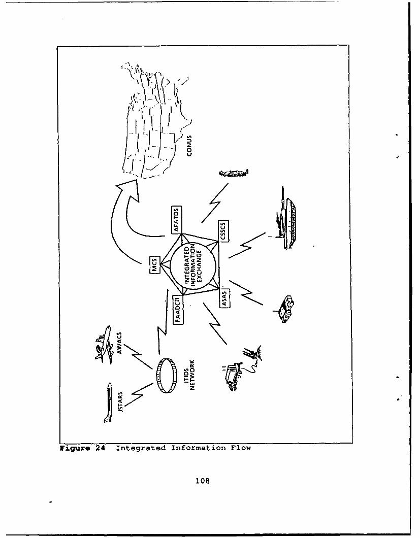
A.- 5
1 z
0
0u
'LA
08
Z. HURDLIS TO OVZRCOMZ
The proper management of information on the battlefield
will enable unit commanders to successfully accomplish the
combat mission. The dramatic increase in the capabilities of
weapon systems and sensors continually drive the need for
better tools to effectively manage these assets. The U.S.
Army has taken the first tentative steps towards this goal in
its development of automated tools for use by the unit
commander. The challenge that faces the Army today is the
integration of these automated systems. The problems
associated with system integration are numerous and must be
tackled one by one.
1. Data Fusion
Modern battlefield sensors produce a vast quantity of
raw data. This data, in its raw form, is of little use to
commanders and their staffs. The data must be processed in
such a way that it becomes manageable information. This
process must be performed for each sensor on the battlefield.
Systems, such as the GSM, are currently under development to
process raw sensor data. The greatest challenge lies in the
incorporation of the data produced by the vast array of
sensors on the battlefield. [Ref. 36:p 41]
System integrators must develop computer software
algorithms that will fuse the data available from all sources
into a coherent picture of the battlefield. The battle
109
picture developed through data fusion must be available to
all users. In order for this to occur the data capacities of
all users must be determined along with user information
requirements. A user with a 16Kbs data capability cannot
process all of the information available on the network. An
automated system would be needed to package the information in
a format readily available to the user which conforms to
predetermined requirements.
2. Decision Support Algorithms
The pace of modern warfare has increased dramatically
over the past two decades. Smarter weapons, with increased
range and lethality, are the norm. Combat commanders can no
longer rely on manual systems to command and control their
forces. Automated tools must be provided for commanders to
employ their forces in a manner that will achieve maximum
results.
ALB-F requires a high degree of agility with precise
synchronization of forces. This can only be achieved with the
development and incorporation of decision support software
tools or algorithms. Military software developers must
remember that processing and displaying combat information is
only one half of the problem. The second half of the problem
is managing the decision making process based on the ever
increasing amount of available information. Commanders are
becoming swamped with information. The commander's ability to
110
assess the situation and determine a course of action is
hindered by the vast amount of information available. The
demand for software across all of DOD is increasing at an
alarming rate. Greater emphasis must be placed on common
software development. Common software must become the
standard if total system integration is to be achieved. A
number of programs have been instituted with this goal in
mind. Selecting Ada as the standard computer language and the
institution of the CHS program are important steps towards
integration. [Ref. 22:p 31]
3. Multilevel Security
A fully integrated automation system does not imply
equal access for all users. The capability to enter and/or
access data must be controlled. Not all users of an Automated
Information System (AIS) possess the required security
clearance for all of the data being processed by the AIS. A
Multilevel Security (MLS) system must be put in place. Access
control to the information available can be accomplished in
many ways that are transparent to the user.
The effective use of Communications Security (COMSEC)
devices will assist in denying data access and analysis during
transmission. The devices will secure the data only while it
is in the network. COMSEC devices will be essential to
protect information traffic passing over the Wide Area Network
(WAN).
ill
A system of passwords must be established for
battlefield system users. Particular passwords will grant
access to particular portions of the information base.
Passwords will define the user's access capability. The
system will know what information the user will be permitted
to read and what information the user may edit. Inherent in
this system is a dependance on trusted software. All
available information must be present in the network, but not
all users should have full access to it.
4. Doctrine
U.S. Army doctrine for the foreseeable future is
stated in ALB-F. This doctrine explains how Army units are to
fight in future conflicts. Other doctrine must be developed
which will tell ATCCS users how the system will be employed.
Management of the network and the information available on it
must be established and procedures determined.
The explosion of information on the battlefield will
require personnel that can manage this information and act as
system integrators. BFA managers will necessarily be required
to manage the information that will continually flow between
C2 elements. The increased use of portable computers by the
military in the field will require soldiers with specialized
skills in system integration on the hardware level. [Ref.
37:p 12] Figure 25 represents future ATCCS management.
112
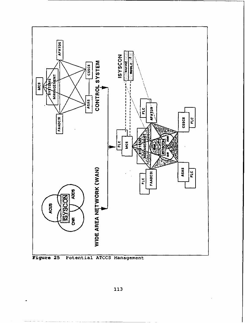
z
UIj
in I
U
IIg
IL d
4zw
Figur~e 25 Potential ATCCS Management
113

5. Summary
This conceptualization of the potential capabilities
of JTIDS provided information is by no means complete.
Further investigation of these proposals is essential to
determine their feasibility. They are the author's proposed
viewed and do not necessarily represent current trends in
system development.
114

CHAPTER VI. CONCLUSIONS AND RECOMMENDATIONS
A. SUMIARY
This thesis has presented JTIDS under its command and
control aspects. An examination of JTIDS potential
applications was also performed. A number of proposals were
developed for the use of JTIDS provided information. The
primary information source examined was the U.S. Air Force
JSTARS ground surveillance aircraft. The use of JSTARS
information, transmitted over JTIDS, on the ATCCS was also
discussed.
B. CONCLUSIONS
The need for a secure , jam-resistant, data distribution
system has been well documented. Numerous communities of all
the services have approved operational requirements for such
a system. JTIDS, in conjunction with EPLRS, will meet this
requirement for the Army. The JSTARS ground surveillance
aircraft can generate a wealth of information pertaining to
enemy mobile targets. This information is invaluable to all
Army commanders. Efforts should be directed towards making
this information available to Army C2 elements at all
echelons. Due to future decreases in resources, the current
Army communication architecture must be adapted to pass this
traffic.
115
Airland Battle-Future doctrine is the future of the U.S.
Army. Successful employment of this doctrine requires the
complete integration of the ATCCS. JTIDS will be an integral
part of the system. JTIDS should be fielded in the near
future, if its full potential is to be realized. There is no
other system in development which will meet the Army's data
distribution needs.
C. MECOfMENDATIONS
1. Timely Fielding
The development of a secure, jam-resistant, data
distribution system has been ongoing since the early 1970's.
The result of this development effort is JTIDS. Studies have
shown that the potential of JTIDS to meet established
requirements is near fruition. JTIDS must be fielded soon if
it is ever to become the joint system it was designed to be.
2. Continued JTIDS Development
Efforts in two areas of JTIDS development must
continue. First, the MIDS program, under its initial
conceptualization, should take advantage of newer technology
to reduce the size of the JTIDS terminals. Complete
integration of the air battle will never occur until the
terminal can be incorporated into the smaller combat aircraft
of the U.S. and our allies. Second, efforts need to continue
on all JTIDS interfaces. All JTIDS terminals should be
adapted to interact with the platforms planned for JTIDS
116

augmentation. Technology development will aid in the
reduction of interface devices and increase the system's
potential uses.
3. NCS-J - The Joint Management Tool
The Army's development of the NCS-J displays the
difficulties encountered in managing an extremely complex
JTIDS network. The NCS-J is a key start point towards reliable
network management. Each service that plans to field JTIDS
should examine its potential to manage the network closely.
JTIDS is far too complex to manage manually and any
reconfiguration of the network would be almost impossible to
handle. The services can adapt the NCS-J to meet their
specific needs, but the basic framework of t~e system should
remain the same for all users.
4. JTIDS Transmission of JSTARS Information
The potential applications for JSTARS provided
information are enormous. JTIDS should be examined as the
means to transmit JSTARS information to all users. Full
exploitation of JSTARS can occur if JTIDS is incorporated into
a fully integrated ATCCS. Once it is available to ATCCS
users, applications of this information can be adapted to
specific BFA users. This facilitates the development of
software which will assist commanders in evaluating all
available information and make the best command decision
117
possible. The complete integration of information systems
will act as a strong force multiplier.
i
118
LIST OF REFZ RmcS
1. Mitre Corporation, Overview Description, TDMAJTIDS, Revision 1, May 1984.
2. Cushman, John H., LtGen USA, "Joint Commandand Control," Military Review, July 1990.
3. Ethell, Jeffrey and Price, Alfred, One Day ina Long War, Random House, Inc., 1989.
4. Air Force System Command, Joint ProgramManagement Plan, Joint Tactical InformationDistribution System, August 1990.
5. Air Force System Command, JTIDS SystemOperations Manual, IOT&E Version, Volume 1,Revision 1, July 1986.
6. Jaszka, Paul R., "JTIDS - A Primary DataLink," Defense Electronics, February 1989.
7. Naval Ocean Systems Center, Support Analysisfor the TADIL J Test System, July 1987.
8. Comptroller General of the United States,"The Joint Tactical Information DistributionSystem - How Important Is It?", Report to theCongress of the United States, PSAD-80-22, 30January 1980.
9. Comptroller General of the United States,"Joint Tactical Information DistributionSystem Class 2 Terminal," Report to theCongress of the United States, PSAD-90-159,10 February 1990.
10. Kirkpatrick, Kenneth A., "Cutting the GordianKnot: The New Air Force Architecture forAnti-Jam Communications," Signal, November1984.
11. "JTIDS Joint Program Planning Office Focuseson Reliability, Lower Unit Cost," AviationWeek and Space Technology, June 1990.
119

12. DOD JOPM Supervisory Working Group, "JointTactical Information Distribution System(JTIDS) Operational Performance in the F-15Theater Defensive Counterair Mission," JTIDSOperational Performance Model (JOPM),November 1988.
13. Mitre Corporation, Army System OperationsTraining Course, October/November 1989.
14. Ellingson, Carl E., System Engineering atMitre: A Case History of JTIDS, Video Tape,Session 2, 1988.
15. Telephone conversation between David S.Velasquez, CPT, USA, JTIDS MaterialManagement, Directorate of CombatDevelopments, U.S. Army Signal Center, Ft.Gordon, GA, and the author 16 January 1991.
16. JTIDS Material Management, Directorate ofCombat Development, What Rides On What?, U.S.Army Signal Center, Ft. Gordon, GA, March1989.
17. Headquarters, Department of the Army, FieldManual 44-1, U.S. Army Air Defense ArtilleryEmployment, Government Printing Office,Washington, DC, 1984.
18. Headquarters, Department of the Army, JTIDSJoint Concept of Operations Manual,Government Printing Office, Washington, DC,1989.
19. Headquarters, Department of the Army, FieldManual 100-5, Operations, Government PrintingOffice, Washington, DC, 1986.
20. Joint Chiefs of Staff, Department of Defense,Dictionary of Military and Associated Terms,Government Printing Office, Washington, DC,1987.
21. Dacunto, Lawrence J., Col (Ret.), USA, "ArmyCommand and Control Initiatives," Signal,November 1988.
22. Wagner, Louis C., Gen, USA, "Modernizing theArmy's C31," Signal, January 1989.
120
23. Headquarters, Department of the Army, FieldManual 11-30, MSE Corps/Division Signal UnitOperations (Coordinating Draft), GovernmentPrinting Office, Washington, DC, 1987.
24. Castro, Christine, "Tactical VoiceCommunications Become User Friendly," DefenseElectronics, June 1990.
25. Whigham, John A., Col, USA, "TacticalCommunications at Echelons Above Corps,"Signal, September 1988.
26. Rawles, James W., "SINCGARS Second Source:Several Suppliers Seek Selection," DefenseElectronics, January 1988.
27. Whigham, John A., Col, USA, "Improved HighFrequency Radio," Signal, September 1988.
28. Hughes Ground Systems Group, EnhancedPosition Location Reporting System (EPLRS)Technical Description, Fullerton, CA, May1988.
29. Hughes Ground Systems Group, EnhancedPosition Location Reporting System,Fullerton, CA, June 1989.
30. Directorate of Combat Developments, AdaptingSignal Support for Airland Battle-Future,Fort Gordon, GA, January 1991.
31. Colligan, John J., Col, USAF, "JSTARS - TheDeep Look," Signal, January, 1988.
32. Haystead, John, "JSTARS - Real Time Warningand Control for Surface Warfare," DefenseElectronics, July 1990.
33. Rawles, James W., "Part II JSTARS: TheGround Stations," Defense Electronics, August1990.
34. Headquarters, Department of the Army, FieldManual 34-1, Intelligence and ElectronicWarfare Operations, Government PrintingOffice, Washington, DC, July 1987.
121

35. Harmon, William E., BGen USA and Webb,Richard B., Col USA, "Evolution and Progress:The All Source Analysis System/ EnemySituation Correlation Element," Signal,December 1987.
36. Desbois, Michel, "Multisensor Tracking,"Signal, November 1988.
37. Directorate of Combat Developments,Multilevel Security (MLS), Fort Gordon, GA,January 1991.
122
INITIAL DISTRIBUTION LIST
1. Defense Technical Information Center 2Cameron StationAlexandria, Virginia 22304-6145
2. Library, Code 52 2Naval Postgraduate SchoolMonterey, California 93943-5000
3. Director for Command, Control andCommunications Systems, Joint StaffWashington, DC 20318-6000
4. C3 Academic Group, Code CC INaval Postgraduate SchoolMonterey, California 93943-5000
5. BG David J. KelleyU.S. Army Signal Center and Fort GordonATTN: ATZH-DCFort Gordon, Georgia 30905
6. Director of Combat Developments 2U.S. Army Signal Center and Fort GordonATTN: ATZH-CD (CPT David S. Velasquez)Fort Gordon, Georgia 30905
7. TRADOC System Manager-ADDSU.S. Army Signal Center and Fort GordonATTN: ATZH-ADFort Gordon, Georgia 30905
8. Professor Donald A. Lacer, Code CC 1Naval Postgraduate SchoolMonterey, California 93943-5000
9. Professor Michael G. Sovereign, Code OR 1Naval Postgraduate SchoolMonterey, California 93943-5000
10. CPT Richard E.Volz, Jr. 12009 Pine Log RoadAiken, South Carolina 29801
123