Embed Size (px)
Citation preview
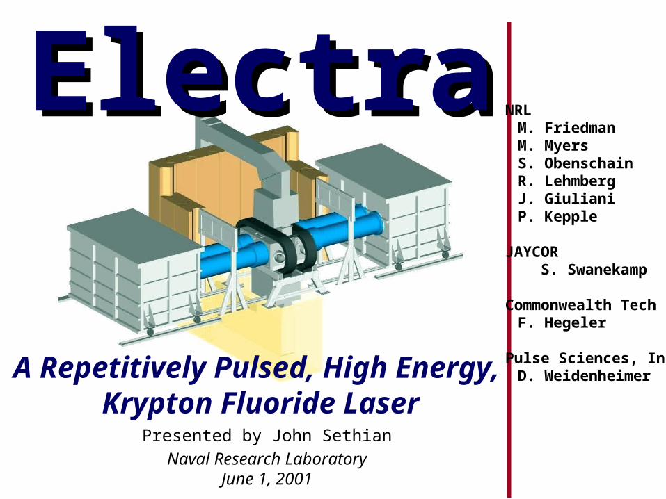
Naval Research LaboratoryJune 1, 2001
Electra title page
A Repetitively Pulsed, High Energy, Krypton Fluoride Laser
ElectraElectra
Presented by John Sethian
NRLM. FriedmanM. MyersS. ObenschainR. LehmbergJ. GiulianiP. Kepple
JAYCOR S. Swanekamp
Commonwealth TechF. Hegeler
Pulse Sciences, IncD. Weidenheimer

Topics this time
Laser GasRecirculator
LaserInput
OutputOptics
Laser Kinetics
Advanced Pulsed Power System (D. Weidenheimer, Titan PSI)
FoilSupport(Hibachi) Amplifier
Window
Cathode

We have looked at 18 types of cathodes/materials
“You have to kiss a lot of frogs to find a prince” Norman Rostoker
Cathode workshop on May 10 at NRL held by F. Hegeler
The bestso far
•Dielectric Fiber-Double Velvet-Other Velvets-Glass
•Carbon-Fiber-Cloth-Foam 100 ppi-Foam 500 ppi-Flock -2% (ESLI)
•Metal/Dielectric-Ceramic/Honeycomb-Metal/ceramic surface flashover-RHEPP-Fine scale RHEPP
•Patched Cathodes-Silicon Carbide-Carbon/Carbon Fiber-Diamond-like Carbon
•CsI Coated Patches-Double Velvet-Carbon/Carbon ESLI-Silicon Carbide
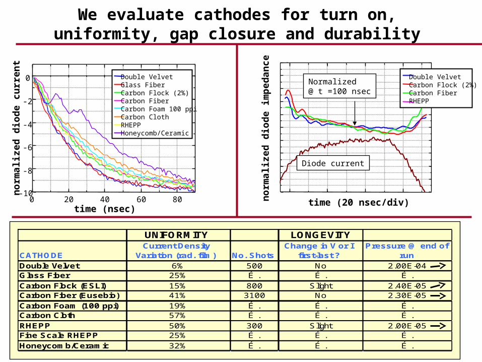
We evaluate cathodes for turn on, uniformity, gap closure and durability
-10
-8
-6
-4
-2
0
0 20 40 60 80
no
rmal
ize
d d
iod
e cu
rre
nt
time (nsec)
Double Velvet Glass FiberCarbon Flock (2%)Carbon FiberCarbon Foam 100 ppiCarbon ClothRHEPPHoneycomb/Ceramic
0.5
0.6
0.7
0.8
0.9
1.0
1.1
1.2
1.3
1.4
1.5
UNIFORMITY LONGEVITY
CATHODECurrent Density
Variation (rad. film) No. ShotsChange in V or I
first-last ?Pressure @ end of
run
Double Velvet 6% 500 No 2.00E-04Glass Fiber 25% É . É . É .
Carbon Flock (ESLI) 15% 800 Slight 2.40E-05Carbon Fiber (Eusebio) 41% 3100 No 2.30E-05
Carbon Foam (100 ppi) 19% É . É . É .Carbon Cloth 57% É . É . É .
RHEPP 50% 300 Slight 2.00E-05Fine Scale RHEPP 25% É . É . É .
Honeycomb/Ceramic 32% É . É . É .
time (20 nsec/div)
no
rmal
ize
d d
iod
e im
ped
an
ce
Diode current
Normalized@ t =100 nsec
Double VelvetCarbon Flock (2%)Carbon FiberRHEPP

0 5 10 15 20 25 300
5
10
15
20
25
30
35
Edeposited
(keV/electron)
X (CM)
We are developing the emitter & hibachi as a single system
Baseline Design: Pattern emitter to miss hibachi ribsFlow water through ribs for cooling
Step 1: 1-D Energy deposition profileshows 78.6%deposited in gas @ 500 keVLaser Gas
Watercooled rib
Laser GasKr + Ar
1.33 atm
Emitter
Vacuum
.01”Ti Foil
Foil loading 0.9 W/cm2
e-beam
1. Transmission
2. Foil cooling
3. Pattern the beam (to miss the ribs)
4. Ribs provide a electrically flat anode
5. Beam uniformly pumps laser gas
84% at 700 keV
e-beam
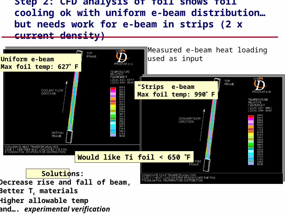
Step 2: CFD analysis of foil shows foil cooling ok with uniform e-beam distribution…but needs work for e-beam in strips (2 x current density)
Solutions:•Decrease rise and fall of beam,•Better Tc materials•Higher allowable temp•and…. experimental verification
Uniform e-beamMax foil temp: 627 F
“Strips” e-beamMax foil temp: 990 F
Measured e-beam heat loadingused as input
Would like Ti foil < 650 F

Step 3: We can pattern the electron beam
Radiachromic Film at anode (5 X Mag)
PATCH CATHODE (3 cm x 3 cm)
STRIP CATHODE(3 cm x 1 cm)
Actual cathode hasfiner spacing andsome sections removed
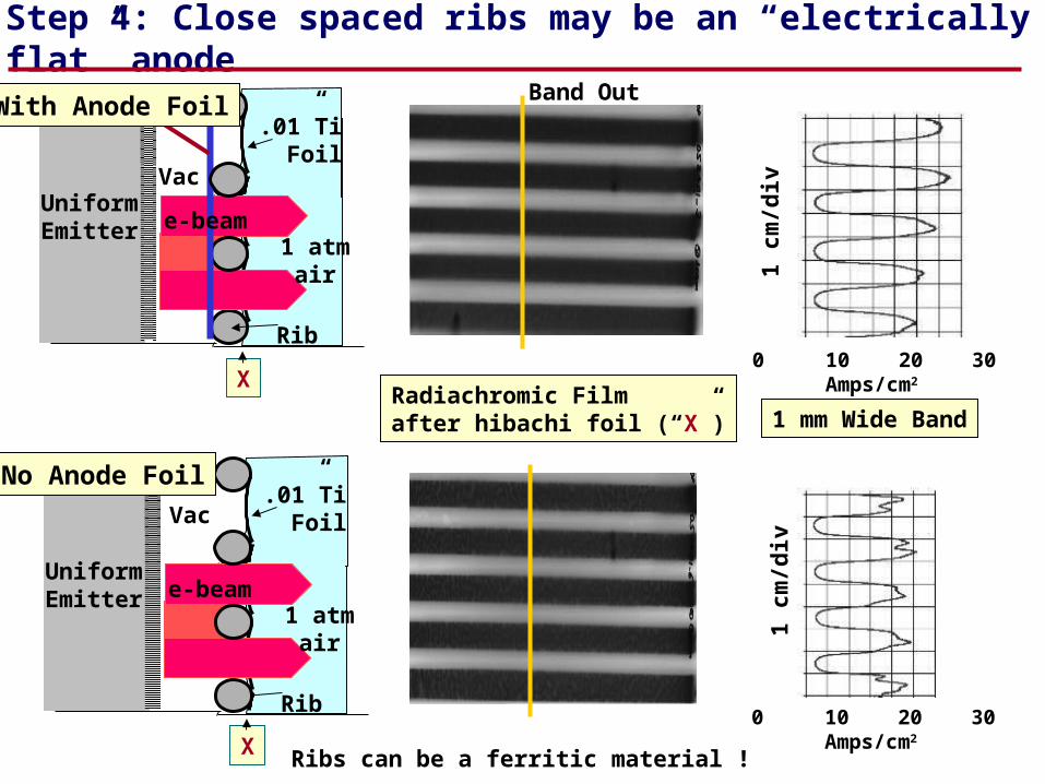
Step 4: Close spaced ribs may be an “electrically flat” anode
Rib
UniformEmitter
Vac.01”Ti Foil
e-beam1 atm
air
No Anode Foil
0 10 20 30 Amps/cm2
Radiachromic Filmafter hibachi foil (“X”)
Rib
UniformEmitter
Vac
.01”Ti Foil
1 atmair
e-beam
X
1 cm
/div
With Anode Foil
1 mm Wide Band
Ribs can be a ferritic material !X0 10 20 30 Amps/cm2
1 cm
/div
Band Out
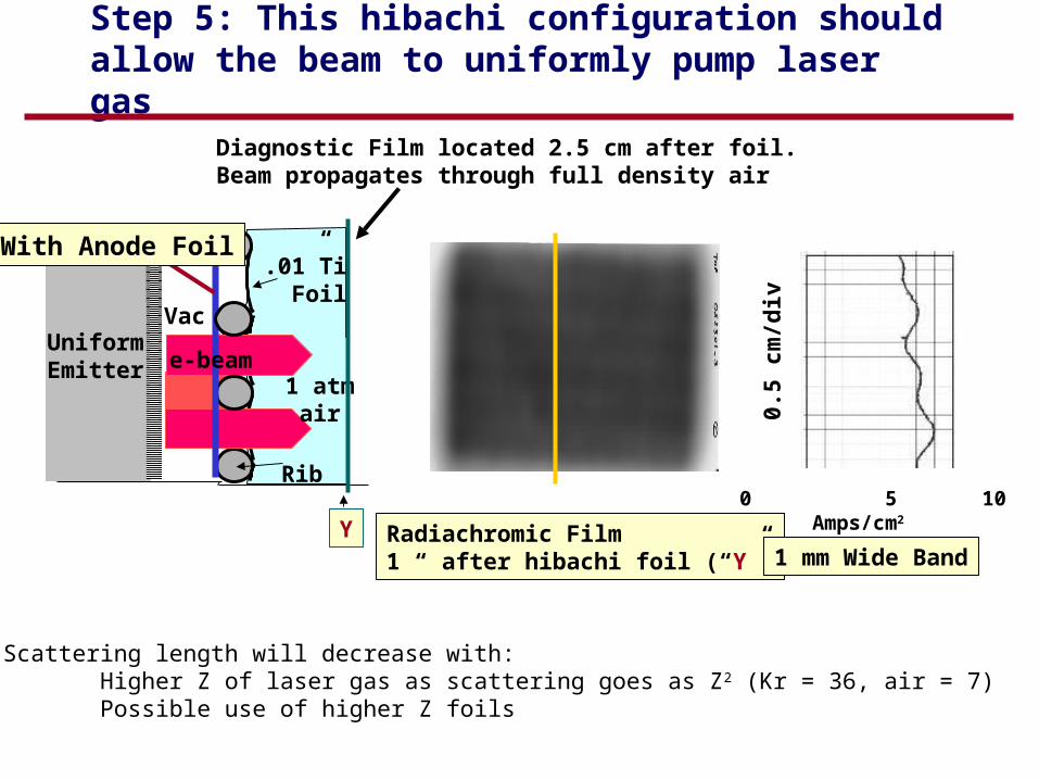
Step 5: This hibachi configuration should allow the beam to uniformly pump laser gas
0 5 10 Amps/cm2
Y Radiachromic Film1 “ after hibachi foil (“Y”)
0.5
cm/d
iv
1 mm Wide Band
Rib
UniformEmitter
Vac
.01”Ti Foil
1 atmair
e-beam
Diagnostic Film located 2.5 cm after foil.Beam propagates through full density air
With Anode Foil
Scattering length will decrease with: Higher Z of laser gas as scattering goes as Z2 (Kr = 36, air = 7) Possible use of higher Z foils
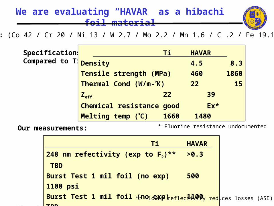
We are evaluating “HAVAR” as a hibachi foil material
HAVAR: (Co 42 / Cr 20 / Ni 13 / W 2.7 / Mo 2.2 / Mn 1.6 / C .2 / Fe 19.1 )
Specifications,Compared to Ti:
Ti HAVAR
Density 4.5 8.3
Tensile strength (MPa) 460 1860
Thermal Cond (W/m-K) 22 15
Zeff 22 39
Chemical resistance good Ex*
Melting temp (C) 1660 1480
248 nm reflectivity @ 80 (angle)- after exposure to F2 (lower reflectivity reduces ASE)
Ti > 0.3 HAVAR: TBD
Burst Strength:
Our measurements: * Fluorine resistance undocumented
Ti HAVAR
248 nm refectivity (exp to F2)** >0.3 TBD
Burst Test 1 mil foil (no exp) 500 1100 psi
Burst Test 1 mil foil (no exp) 1100 TBD
Burst test 2 mil foil (exp to F2) 1100 TBD
** lower reflectivity reduces losses (ASE)

Doug WeidenheimerTitan-PSI
onAdvanced Pulsed Power for Electra

Summary of progress since last meeting
Ultimate cathode is still elusive, but have candidates
New Baseline Hibachi design looks good so far, Needs more testing
Advanced Pulsed Power program developing components
Identified three systems that can meet requirementsStarted component development
Advanced photonically triggered switchesEnd of life testing of existing components