Embed Size (px)
Citation preview
NAVAL POSTGRADUATE SCHOOLMONTEREY, CALIFORNIA o-/
(0
N=
D•TIC
MAR1 ROO4
THESIS
DESIGN OF A COLD-FLOW TEST FACILITYFOR THE HIGH-PRESSURE FUEL TURBOPUMP
TURBINE OF THE SPACE-SHUTTLE MAIN ENGINE
by
Colin C. Studevan
December 1993
Thesis Advisor: Garth V. Hobson
Approved for public release; distribution is unlimited
94-08201
[94 a3

BestAvailable
Copy
Form ApprovedREPORT DOCUMENTATION PAGE OMB No 0704-0188
PuI•Ic retorong bure for thi-. €llegiu of mfoemaon is estimated to average I hour per resOnse. Including the time for reviewing instructions. searching e r•iting data urces.altherig nd maintainng the data nee.ded, ard completigj and reviewi; g the colel 0on of informatiOn Send comments regarding this burden estimate or any other aspect of this
=o.,etion of fnormtlion. inuding suggestions for reducing this burden, to washington HeadQuarters Services. Directorate tor information Operations and Reports. MS JeffersonDavis Highway. Suitt 1204. Arlington. VA 22202-4302. and to the Office of Management and Budget Paperwork Rteduction Protect (0704-01I). Washington. DC 20103
i. AGENCY USE ONLY (Leave blank) 2. REPORT DATE | 3. REPORT TY.IE AND DATES COVERED1993, December I Master's Thesis4. TITLE AND SUBTITLE S. FUNDING NUMBERS
DESIGN OF A COLD-FLOW TEST FACILITY FOR THEHIGH-PRESSURE FUEL TURBOPUMP TURBINE OF THESPACE-SHUTTLE MAIN ENGINE
6. AUTHOR(S)
Colin Charles Studevan
7. PERFORMING ORGANIZATION NAME(S) AND ADDRESS(ES) B. PERFORMING ORGANIZATION
REPORT NUMBER
Naval Postgraduate SchoolMonterey, Ca 93943-5000
g. SPONSORING/MONITORING AGENCY NAME(S) AND ADDRESS(ES) 10. SPONSORING/ MONITORINGAGENCY REPORT NUMBER
11. SUPPLEMENTARY NOTESThe views expressed in this thesis are those of the author and do notreflect the official policy or position of the Department of Defenseor the U.S. Government.
12a. DISTRIBUTION /AVAILABILITY STATEMENT 12b. DISTRIBUTION CODEApproved for public release; distribution isunlimited.
13. ABSTRACT (Maximum 200 words)
The design and installation at the Naval Postgraduate School of acold-flow test facility for the turbine of the high-pressure fuelturbopump of the Space Shuttle Main Engine, is reported. The specificarticle to be tested is the "Alternate Development Model" designedand manufactured by Pratt & Whitney. The design of individualcomponents is documented. The installation of the facility subsystemsis described in detail. A preliminary estimation of turbineperformance is made.
14. SUBJECT TERMS Turbine Test Rig, Alternate Turbopump IS. NUMBER OF PAGES
Development Model, SSME Turbopump Turbine 16. PRICe CODE
17. SECURITY CLASSIFICATION 18. SECURITY CLASSIFICATION 19. SECURITY CLASSIFICATION 20. LIMITATION OF ABSTRACTOF REPORT OF THIS PAGE OF ABSTRACTUnclassified Unclassified Unclassified Unclassified
NSN 7540-01-280-5500 Standard Form 298 (Rev 2-89)NSN 7540.01-280.550 ANSI 'Std Z39-19
i 299-102
Approved for public release; distribution is unlimited.
Design of a Cold-Flow Test Facilityfor the High-Pressure Fuel Turbopump Turbine
of the Space-Shuttle Main Engine
by
Colin C. StudevanLieutenant, United States NavyB.S., U.S. Naval Academy, 1985
Submitted in partial fulfillment
of the requirements for the degree of
MASTER OF SCIENCE IN ASTRONAUTICAL ENGINEERING
from theNAVAL POSTGRADUATE SCHOOL
December 1993
AuthoruoC lin C. Studevan
Approved by:rth V. Hobson, Thesis Advisor
Raf dP Shreeve, Second Reader
Daniel 3.7 C _ns, chairmanDepartment of Aeronautical Engineering
ii
ABSTRACT
The design and installation at the Naval Postgraduate School
of a cold-flow test facility for the turbine of the high
pressure fuel turbopump of the Space Shuttle Main Engine, is
reported. The specific article to be tested is the "Alternate
Development Model" designed and manufactured by Pratt &
Whitney. The design of individual components is documented.
The installation of the facility subsystems is described in
detail. A preliminary estimation of turbine performance is
made.
Accesion For
NTIS CRA&IDFIC IA,
D(•t.'b:,,ioor
Dist
TABLE OF CONTENTS
I. INTRODUCTION ......... . . . ....... 1
II. FACILITY DESIGN AND INSTALLATION . . . . . . . .. 4
A. AIR SUPPLY SYSTEM .. ... ......... 4
B. TURBINE ASSEMBLY . . . . . . ............. 7
C. HYDRAULIC DYNAMOMETER ............. 12
D. LUBRICATION SUBSYSTEM ... .......... 19
E. CONTROL AND INSTRUMENTATION . ........... 19
III. PERFORMANCE ESTIMATION . . . . . .......... . 26
IV. CONCLUSIONS AND RECOMMENDATIONS .... .......... 27
A. CONCLUSIONS ..... ................. . 27
B. RECOMMENDATIONS ..................... 28
APPENDIX I. ENGINEERING DRAWINGS . . . . . . . . . .. 29
APPENDIX II. . . . . . . . . . . . . .......... . 42
LIST OF REFERENCES ............. .................. 44
INITIAL DISTRIBUTION LIST ........ ............... 45
iv
LIST OF FIGURES
Figure 1. Allis-Chalmers Compressor . . . . . . . . 5
Figure 2. Air Supply for the High Speed
Laboratory ...... .............. . . . 6
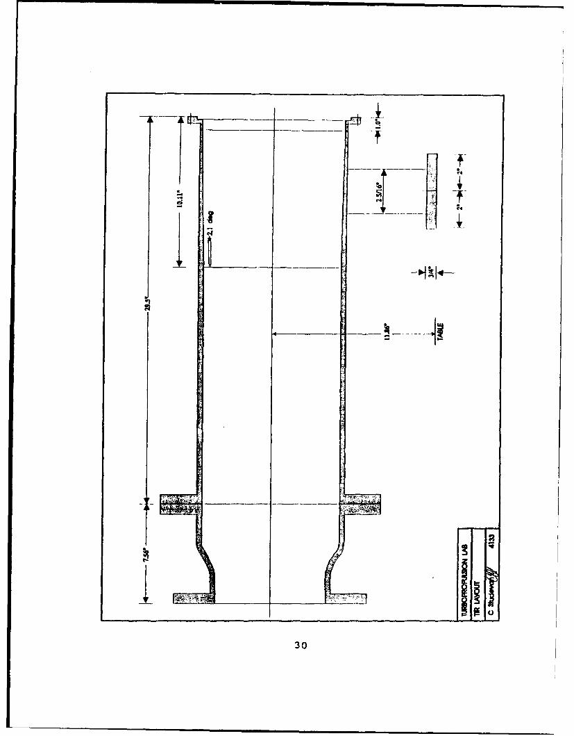
Figure 3. TTR Layout ....................... 8
Figure 4. Test Rotor with Sample Blading .... ....... 10
Figure 5. Bearing Sleeve Assembly . ......... .. 13
Figure 6. Hydraulic Dynamometer . . . ........... 14
Figure 7. Schematic of the Automatic Dynamometer
Load Control System ....... .............. 16
Figure 8. Fifty-Gallon Holding Tank and Pump ..... .. 18
Figure 9. Portable Turbine Lubrication Unit . .... 20
Figure 10. Bearing Lubrication Path . ......... 21
Figure 11. Inlet and Outlet Control Valves ...... .. 23
Figure 12. TTR Control Console . . . . . . . . . . . . 24
v
I. INTRODUCTION
The purpose of this report is to describe the design and
installation at the Naval Postgraduate School's
Turbopropulsion Laboratory (TPL), of a cold-flow test facility
for a high-work turbine. The test turbine, intended to power
the liquid fuel pump on the Space Shuttle Main Engine (SSME),
was designed and manufactured by Pratt & Whitney (P&W) as the
Alternate Turbopump Development (ATD) model. The original
High-Pressure Fuel Turbopump (HPFTP) for the SSME was designed
and manufactured by Rocketdyne. The HPFTP consists of a high
pressure hydrogen pump driven by a two-stage, axial-flow
turbine. The turbine is a low-pressure ratio reaction turbine
driven by a mixture of steam and gaseous hydrogen. The
turbine produces approximately 73,000 hp. At its design
point, the turbine operates with an inlet temperature of about
1,900°R and an inlet pressure of approximately 5,200 psi.
NASA's Marshall Space Flight Center established a "cold-
flow" testing facility to experimentally determine the
performance of the SSME HPFTP. The facility was a short-
duration, blow-down rig, and the turbine was spun up to speed
prior to activating the airflow. Hudson et al (Ref. 1]
performed the first tests on the Rocketdyne HPFTP. Subsequent
testing of the Pratt & Whitney ATD HPFTP was conducted by
1
Gaddis et al (Ref. 2] for "back-to-back" comparisons with the
Rocketdyne HPFTP. The turbine performance and turbine
parameters such as airfoil surface static pressure
distributions, static pressure drop through the turbine, and
exit swirl angle were investigated at the design point, over
its operating range, and at extreme off-design points. In the
present work, following a program of tests using only a single
stage, two-stage performance data will be obtained and
compared with those reported by Gaddis.
The purpose of the present installation was not primarily
for performance measurements. Rather, it was to continue and
extend a program of time-resolved flow measurements in
turbomachines for the purposes of both evaluating advanced
designs and validating viscous flow analysis codes. The
complex turbine test rig (TTR) at TPL, last reported by Kane
(1978) and Eargle (1980), was not suited for this purpose.
The rig was expressly designed not to require interblade
measurements, could not readily allow access for optical
measurements, and the turbine stages available for the rig
were of no current interest. The rig was therefore removed
from the test cell, and the installation described in the
present document was put in its place. Where possible,
components of the old rig were refurbished and reused (air
supply system, hydraulic dynamometer, test table and rotor
support), however the installation was a complete redesign and
required the manufacture, installation and alignment of all
2
components between the flange from the air supply system and
the drive shaft to the dynamometer.
In the present document, the design and installation of
the new turbine test facility are described. Chapter III
gives results of some preliminary performance predictions for
the rig. Chapter IV contains conclusions and recommendations.
Engineering drawings and other system documentation are
contained in the Appendices. It is noted that the present
documentation was completed prior to initial tests to check
out the installation.
3
II. FACILITY DESIGN AND INSTALLATION
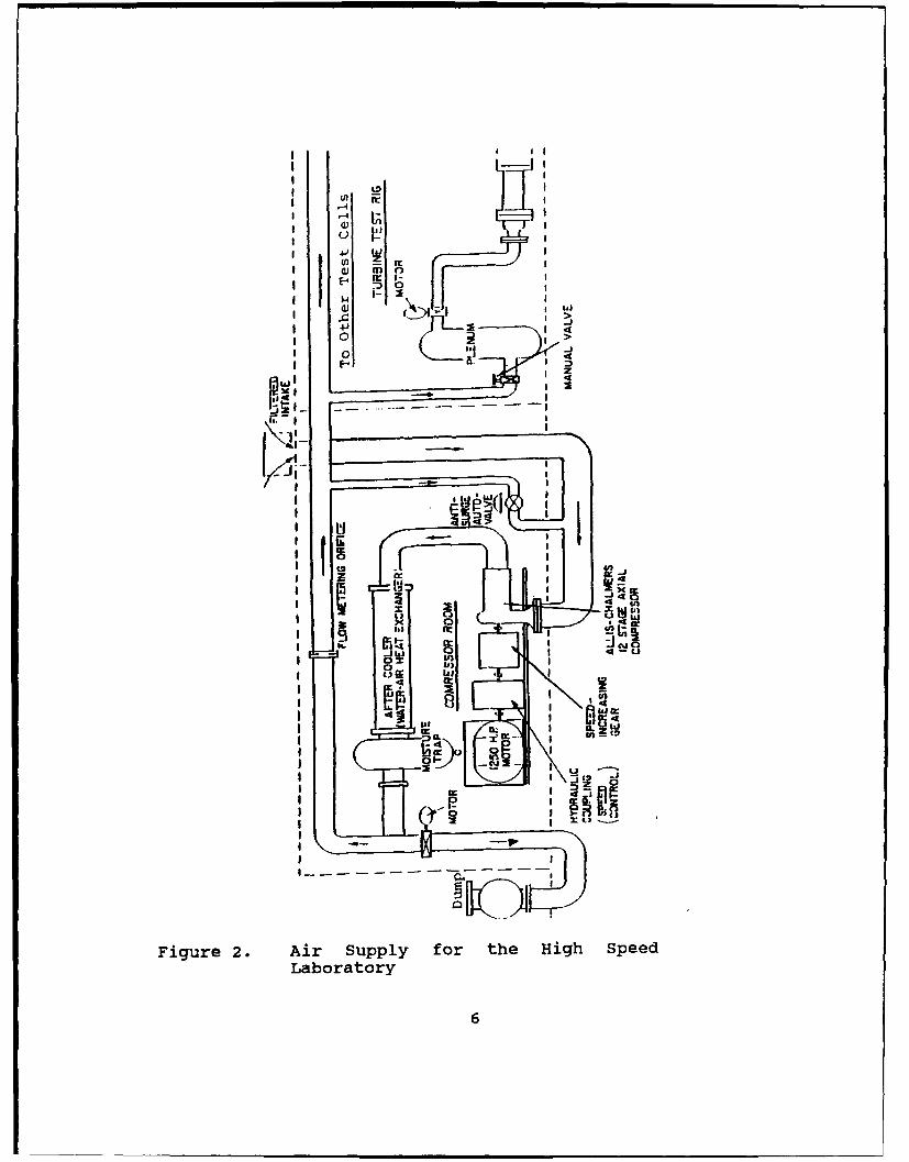
A. AIR SUPPLY SYSTEM
Air to drive the HPFTP turbine was supplied by an Allis-
Chalmers twelve-stage axial compressor. The compressor is
driven by a 1250 horsepower electric motor; at a rotational
speed of 12,000 revolutions per minute, pumping a maximum
volume flow rate of 10,000 cubic feet per minute, to a maximum
pressure ratio of 3 to 1. The Allis-Chalmers compressor is
shown in Figure 1. The air supply system arrangement for the
High Speed Laboratory of the TPL and the test cell is shown in
Figure 2.
During normal operation, air enters the compressor through
a filtered intake open to the atmosphere. The air then passes
through the 12-stage axial compressor, and enters the
aftercooler where the air is cooled to about 110"F. Before
leaving the compressor room, the air flows through a flow
metering orifice in the facility supply line. After entering
the TTR the air flows through a manually-controlled butterfly
valve, before entering the TTR plenum chamber. The air supply
from the plenum chamber is remotely controlled by a motor-
driven butterfly valve. The air exits the plenum chamber
through an eight-inch pipe, passes through an eight-to-ten
4
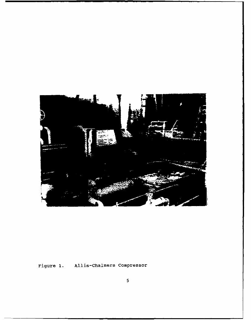
Figure 1. Allis-Chalmers Compressor
5
I I ! ! !
II i
I I
4J4
EI S I3U
t•im an
W- h i
LAS IL IL: t
oi
Fiur 2. Ai..,y o h Hg pe
,I-- I
i I -• I
IIn.-s'
I I n (
Figure 2. Air Supply for the High Speed
Laboratory
6
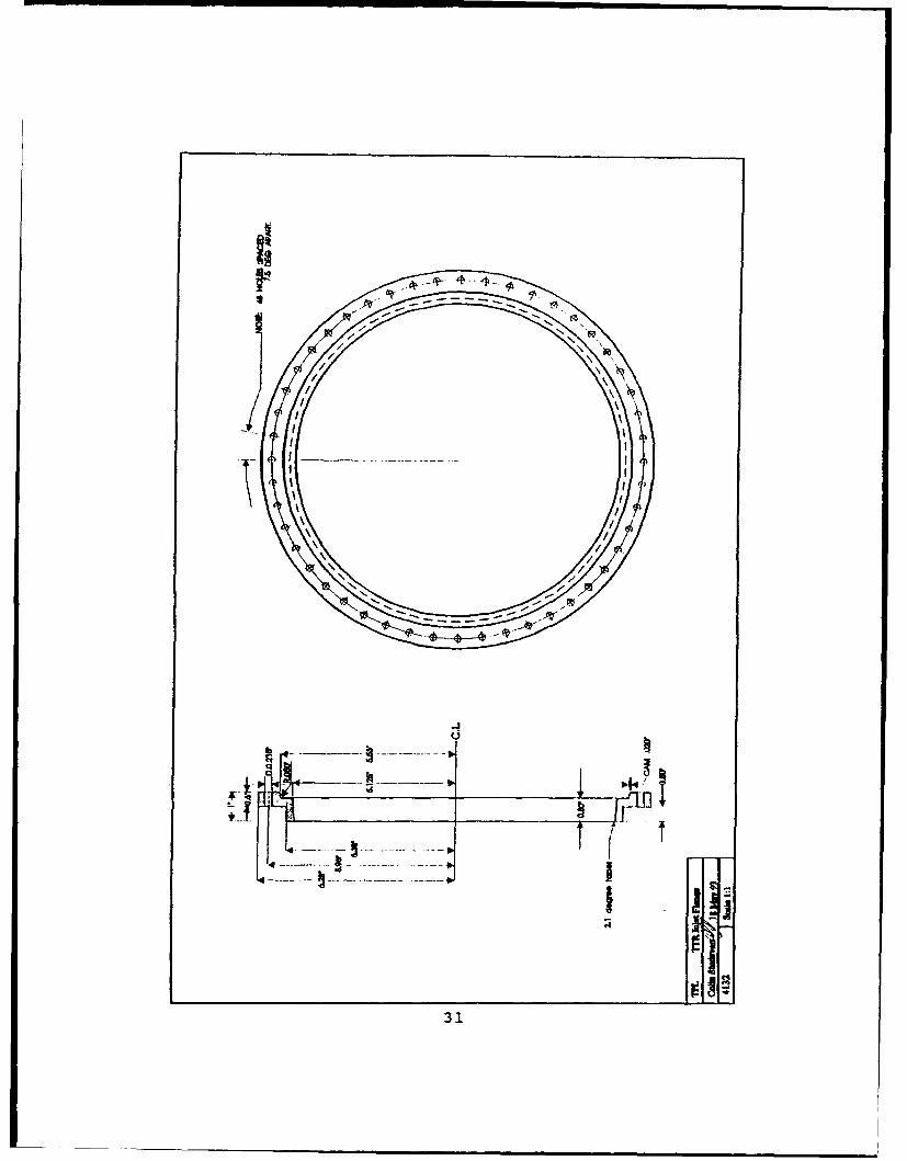
inch pipe expander, and flows into the turbine inlet piping.
A two-degree taper was machined on the inside surface of the
inlet piping which mated flush against the inlet strut housing
of the test turbine. Access holes were drilled at 1200 around
the inlet piping for installing performance instrumentation
such as inlet total pressure and temperature probes.
Engineering drawings of the inlet piping are contained in
Appendix I.
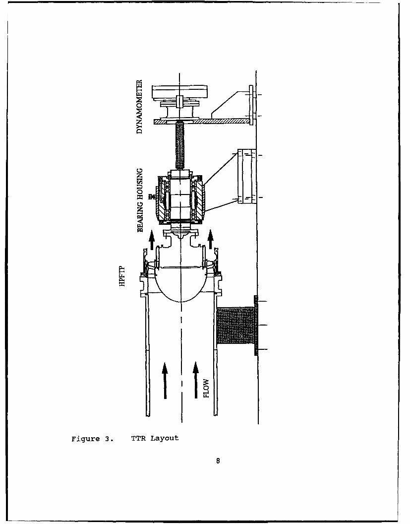
B. TURBINE ASSEMBLY
High pressure air from the inlet piping, flows through the
inlet strut housing into the turbine as shown in Figure 3.
The air then flows axially into the first stage stator which
imparts swirl to the flow. The swirling airflow is turned
through the rotor, which produces shaft power, before
exhausting into the test cell. The shaft power is absorbed by
a water dynamometer, shown schematically in Figure 3.
The HPFTP test specimen was supplied by Pratt and Whitney.
The components which were supplied included the inlet-strut
housing, the test rotor, the first and second stage stator and
rotor blades, the outer casing, and the retainer ring for the
first stage stator.
The remaining components that were needed to complete the
test facility were either designed and machined, or were
purchased from commercial vendors. Drive-shaft components
which were designed included the main bearing shaft, the
7
0-4
0
Figure 3. TTR Layout
8
bearing sleeve, the bearing spacers and retainer rings, and
the oil seals. Component diagrams are contained in Appendix
I.
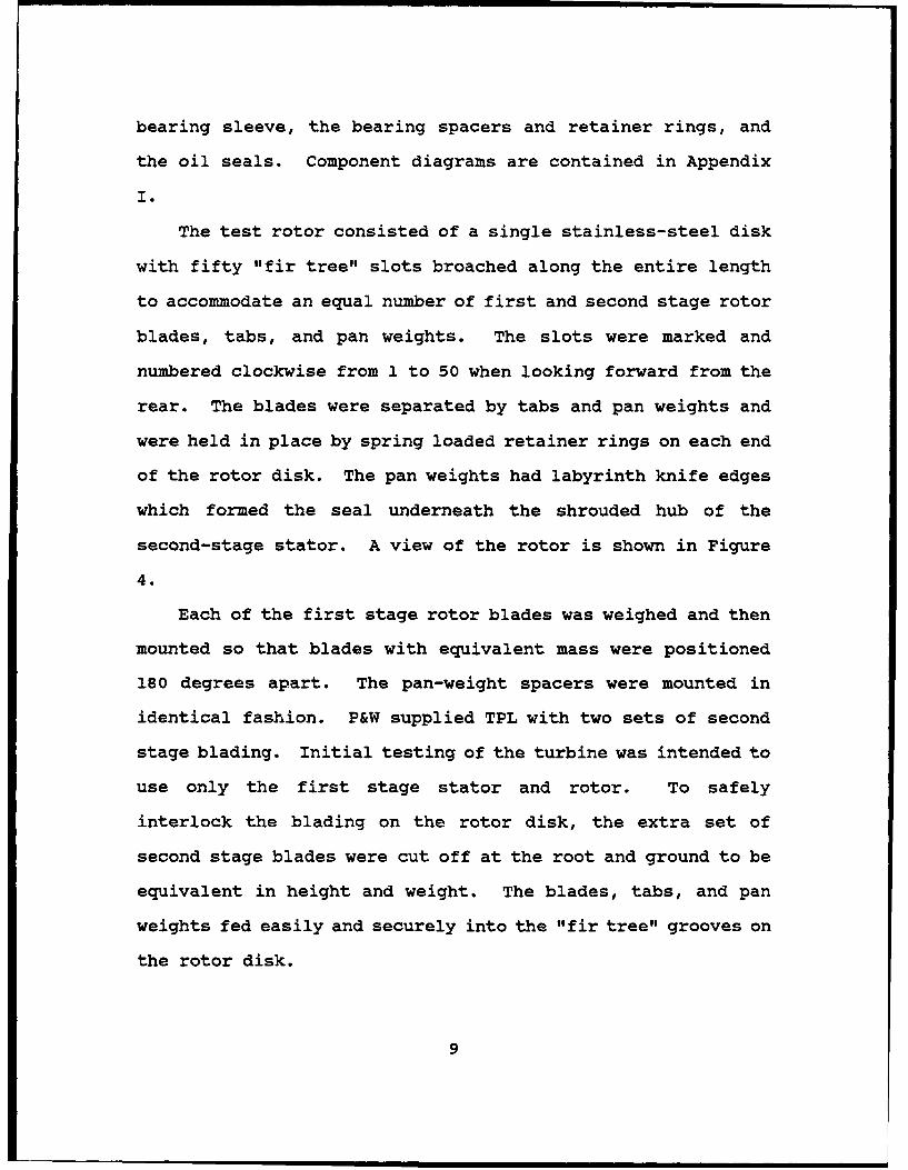
The test rotor consisted of a single stainless-steel disk
with fifty "fir tree" slots broached along the entire length
to accommodate an equal number of first and second stage rotor
blades, tabs, and pan weights. The slots were marked and
numbered clockwise from I to 50 when looking forward from the
rear. The blades were separated by tabs and pan weights and
were held in place by spring loaded retainer rings on each end
of the rotor disk. The pan weights had labyrinth knife edges
which formed the seal underneath the shrouded hub of the
second-stage stator. A view of the rotor is shown in Figure
4.
Each of the first stage rotor blades was weighed and then
mounted so that blades with equivalent mass were positioned
180 degrees apart. The pan-weight spacers were mounted in
identical fashion. P&W supplied TPL with two sets of second
stage blading. Initial testing of the turbine was intended to
use only the first stage stator and rotor. To safely
interlock the blading on the rotor disk, the extra set of
second stage blades were cut off at the root and ground to be
equivalent in height and weight. The blades, tabs, and pan
weights fed easily and securely into the "fir tree" grooves on
the rotor disk.
9
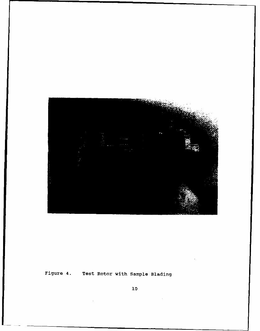
Figure 4. Test Rotor with Sample Blading
10
When mounting these components on the rotor disk, care had
to be taken to ensure a correct fit. The components were
machined to self-lock once in place. To mount correctly,
components were initially slipped into place so that only 1/8"
was inserted into the groove. Then, moving clockwise (looking
forward from the rear), each blade, tab, or pan weight was
slipped into the 1/8" position sequentially until all
components of that row were similarly mounted. Once all
components of that row were inserted 1/8" into the groove,
each blade was slowly moved forward, in sequence, until all
components of that row were in their most forward position
(Fig. 4). An exact listing of individual blade positions is
given in Appendix II.
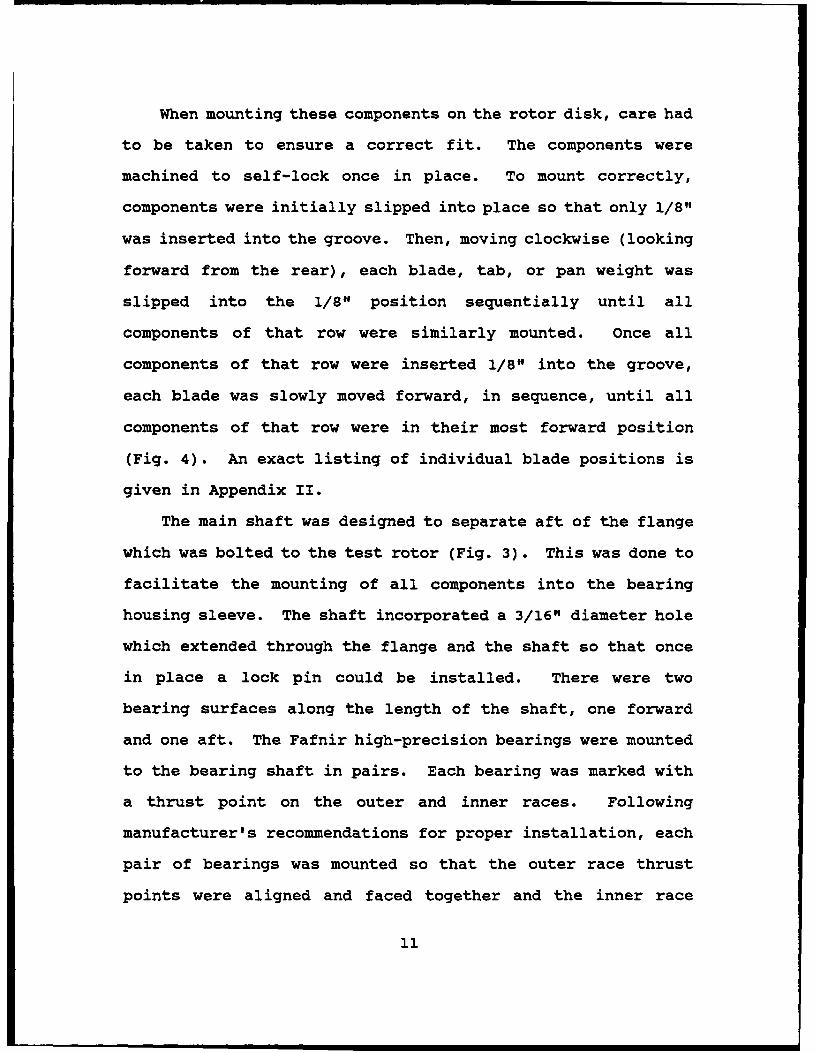
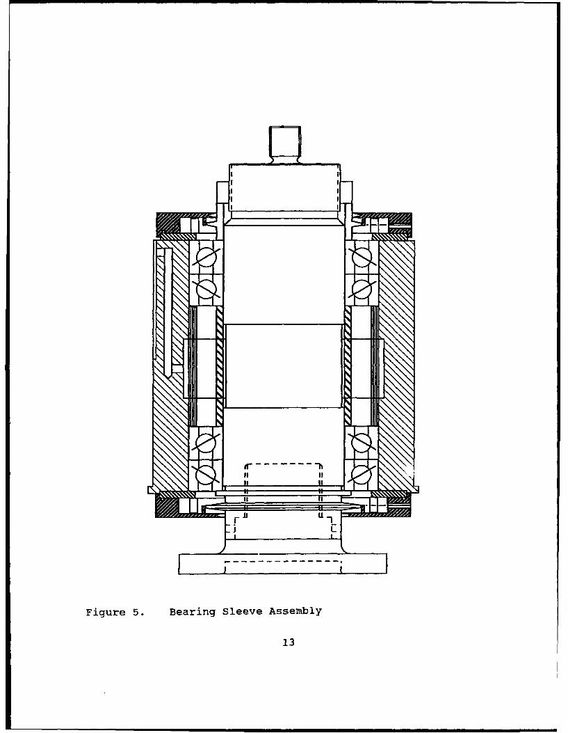
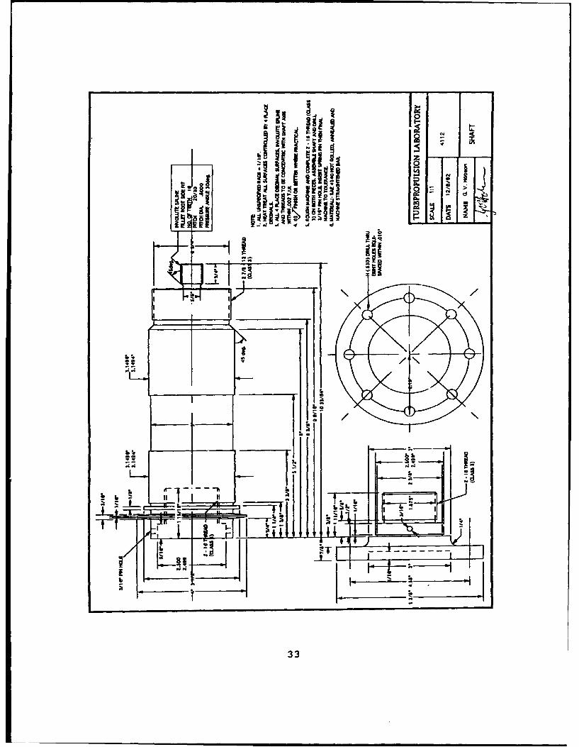
The main shaft was designed to separate aft of the flange
which was bolted to the test rotor (Fig. 3). This was done to
facilitate the mounting of all components into the bearing
housing sleeve. The shaft incorporated a 3/16" diameter hole
which extended through the flange and the shaft so that once
in place a lock pin could be installed. There were two
bearing surfaces along the length of the shaft, one forward
and one aft. The Fafnir high-precision bearings were mounted
to the bearing shaft in pairs. Each bearing was marked with
a thrust point on the outer and inner races. Following
manufacturer's recommendations for proper installation, each
pair of bearings was mounted so that the outer race thrust
points were aligned and faced together and the inner race
11
thrust points were aligned and faced away from each other as
shown in Figure 5.
During assembly, the flange was separated from the main
bearing shaft. The first pair of bearings was inserted onto
the shaft from the aft end and moved forward to rest against
the retainer flange forward of the bearing surface. The
bearing inner spacer was then inserted onto the shaft so that
it rested against the inner race of the first set of bearings.
The bearing outer spacer was inserted over the bearing inner
spacer so that its edges rested against the outer race of the
bearing. The second pair of bearings was then slipped onto
the aft bearing surface of the shaft until the inner race of
the bearing rested against the bearing inner spacer (Fig. 5).
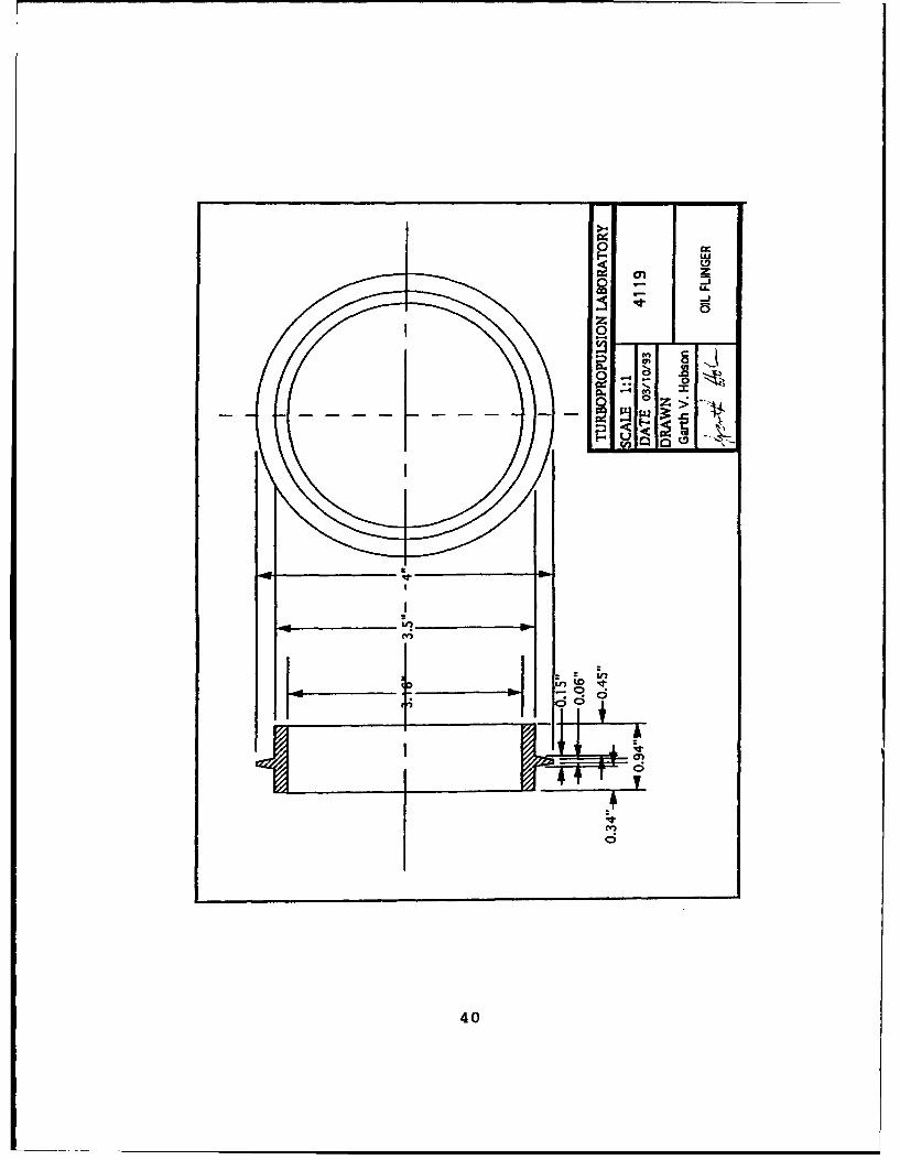
The oil-flinger was mounted onto the shaft against the inner
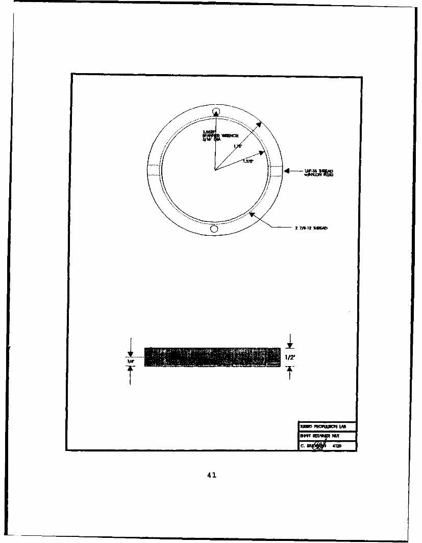
race of the second set of bearings. A circular locking nut
was used at the end of the shaft to secure the components onto
the shaft. The entire assembly was inserted into the main
bearing sleeve. Bearing retainers were then secured to each
end of the sleeve. Installation of the oil-seals over the
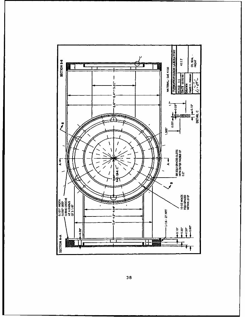
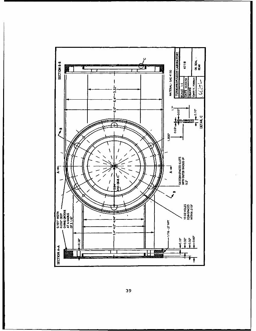
bearing retainers completed the main-bearing sleeve assembly.
C. HYDRAULIC DYNAMOMETER
The energy output of the turbine was designed to be
absorbed by a 250-horsepower Series 061 hydraulic dynamometer
manufactured by Kahn Industries, as shown in Figure 6. A
12
ELL
Figure 5. Bearing Sleeve Assembly
13
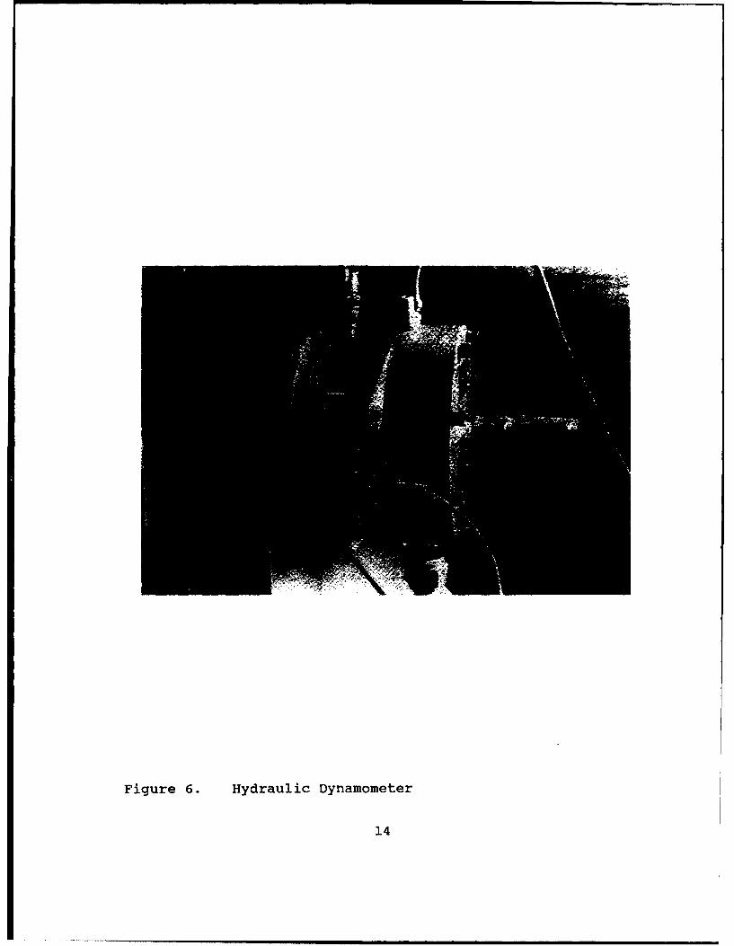
Figure 6. Hydraulic Dynamometer
14
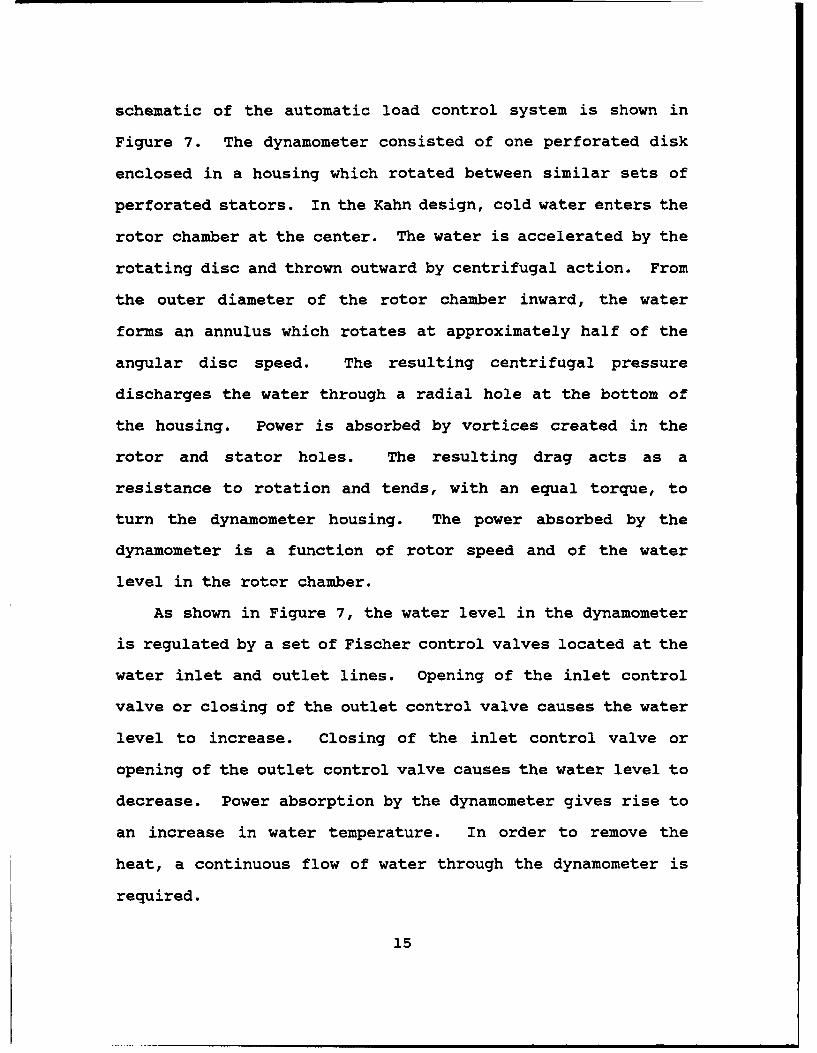
schematic of the automatic load control system is shown in
Figure 7. The dynamometer consisted of one perforated disk
enclosed in a housing which rotated between similar sets of
perforated stators. In the Kahn design, cold water enters the
rotor chamber at the center. The water is accelerated by the
rotating disc and thrown outward by centrifugal action. From
the outer diameter of the rotor chamber inward, the water
forms an annulus which rotates at approximately half of the
angular disc speed. The resulting centrifugal pressure
discharges the water through a radial hole at the bottom of
the housing. Power is absorbed by vortices created in the
rotor and stator holes. The resulting drag acts as a
resistance to rotation and tends, with an equal torque, to
turn the dynamometer housing. The power absorbed by the
dynamometer is a function of rotor speed and of the water
level in the rotor chamber.
As shown in Figure 7, the water level in the dynamometer
is regulated by a set of Fischer control valves located at the
water inlet and outlet lines. Opening of the inlet control
valve or closing of the outlet control valve causes the water
level to increase. Closing of the inlet control valve or
opening of the outlet control valve causes the water level to
decrease. Power absorption by the dynamometer gives rise to
an increase in water temperature. In order to remove the
heat, a continuous flow of water through the dynamometer is
required.
15
tilj
-1~ L
II
110
Figure7. Schematcf teI tm ic
Dam SystIe
16-.
5:--..( >- _"-t i -'-
+-. +,, 1f 4
Figure 7. Schematic of the AutomaticDynamometer Load Control System
16
The present installation was changed from the installation
described in Kane (Ref. 3) because changes had been made in
the water cooling system for the Allis-Chalmers compressor.
Water was supplied to the dynamometer, from the Allis-Chalmers
cooling system, at a constant pressure of 50 psi. It entered
the inlet control valve, flowed through the dynamometer
housing, and exited through the outlet control valve and
dumped into a fifty gallon holding tank at atmospheric
pressure. The water was then pumped back into the
pressurized, closed-loop system by a Gould nine-stage
centrifugal pump located at the base of the holding tank.
The water level in the holding tank was set by the
position of three electronic probes, which were inserted into
the top of the holding tank, as shown in Figure 8. The probes
were connected to a Warrick controller which controlled the
on-off cycle of the Gould 9-stage pump. These probes were set
so that the pump switched to the ON position when the water
level reached the desired high point, and switched OFF when it
reached the desired low point. The low point was chosen to
avoid running the holding tank dry and damaging the pump.
Initial testing of the system revealed that the cyclic
operation of the pump had a adverse effect on the ability of
the system to maintain a constant pressure. Continuous
operation of the pump, by controlling the rate at which the
water was returned to the closed-loop system, corrected the
problem, and enabled the system to maintain a constant
17
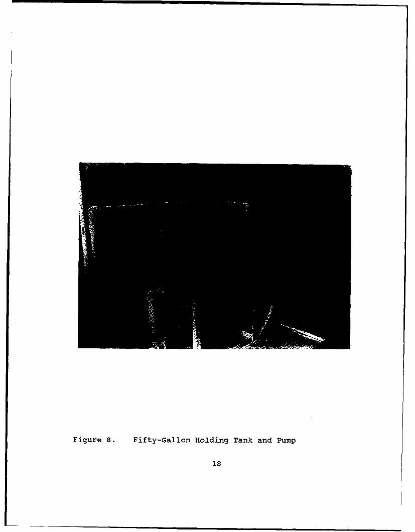
Figure 8. Fifty-Gallon Holding Tank and Pump
18
pressure. To control the rate of water return, a manually-
controlled restriction valve was installed downstream of the
Gould water pump. By maintaining a near constant level in the
holding tank, the system pressure remained constant.
D. LUBRICATION SUBSYSTEM
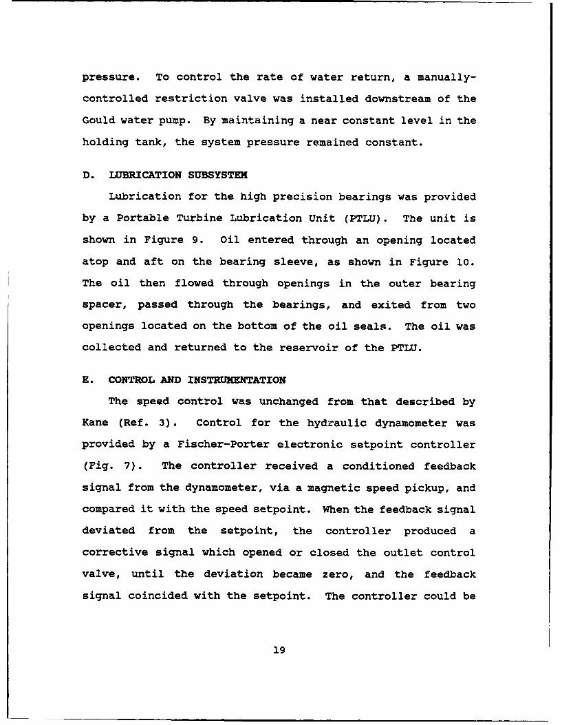
Lubrication for the high precision bearings was provided
by a Portable Turbine Lubrication Unit (PTLU). The unit is
shown in Figure 9. Oil entered through an opening located
atop and aft on the bearing sleeve, as shown in Figure 10.
The oil then flowed through openings in the outer bearing
spacer, passed through the bearings, and exited from two
openings located on the bottom of the oil seals. The oil was
collected and returned to the reservoir of the PTLU.
E. CONTROL AND INSTRUMENTATION
The speed control was unchanged from that described by
Kane (Ref. 3). Control for the hydraulic dynamometer was
provided by a Fischer-Porter electronic setpoint controller
(Fig. 7). The controller received a conditioned feedback
signal from the dynamometer, via a magnetic speed pickup, and
compared it with the speed setpoint. When the feedback signal
deviated from the setpoint, the controller produced a
corrective signal which opened or closed the outlet control
valve, until the deviation became zero, and the feedback
signal coincided with the setpoint. The controller could be
19
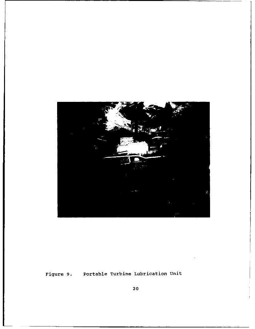
Figure 9. Portable Turbine Lubrication Unit
20
Figure 10. Bearing Lubrication Path
21
set to automatic or operated manually. The inlet-control
valve was used to adjust the water flow rate for a particular
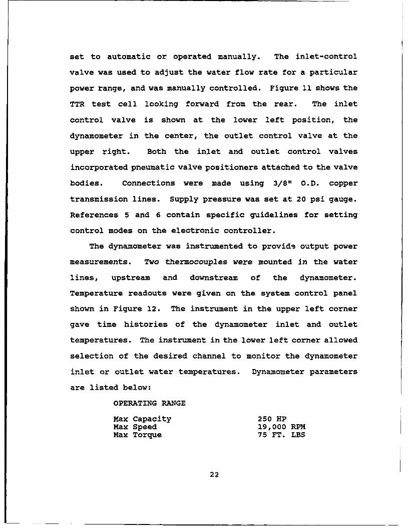
power range, and was manually controlled. Figure 11 shows the
TTR test cell looking forward from the rear. The inlet
control valve is shown at the lower left position, the
dynamometer in the center, the outlet control valve at the
upper right. Both the inlet and outlet control valves
incorporated pneumatic valve positioners attached to the valve
bodies. Connections were made using 3/8" O.D. copper
transmission lines. Supply pressure was set at 20 psi gauge.
References 5 and 6 contain specific guidelines for setting
control modes on the electronic controller.
The dynamometer was instrumented to provids output power
measurements. Two thermocouples were mounted in the water
lines, upstream and downstream of the dynamometer.
Temperature readouts were given on the system control panel
shown in Figure 12. The instrument in the upper left corner
gave time histories of the dynamometer inlet and outlet
temperatures. The instrument in the lower left corner allowed
selection of the desired channel to monitor the dynamometer
inlet or outlet water temperatures. Dynamometer parameters
are listed below:
OPERATING RANGE
Max Capacity 250 HPMax Speed 19,000 RPMMax Torque 75 FT. LBS
22
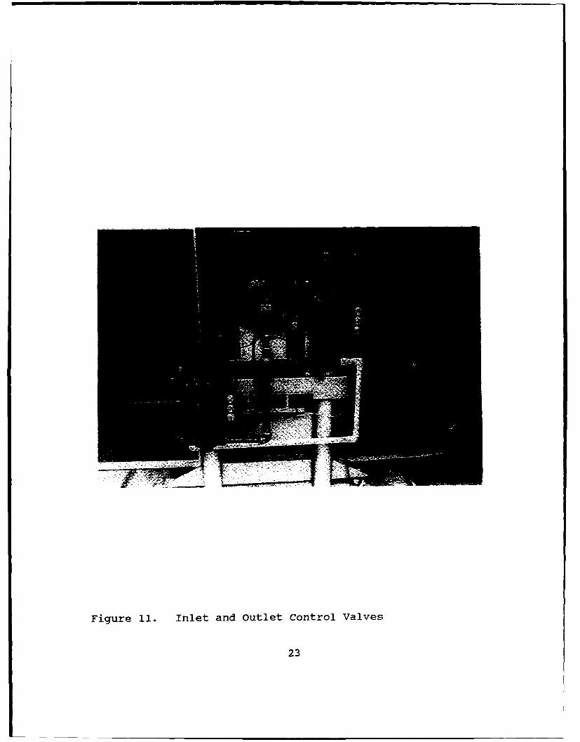
Figure 11. Inlet and Outlet Control Valves
23
- 7! !
Figure 12. TTR Control Console
24
WATER SUPPLY REQUIREMENTS
Water Flow @ Delta T= 76"F 4 GPH/HPSupply Pressure 50 psigMax Inlet Temp 800 FMax Outlet Temp 156° F
A water flowmeter was also installed upstream of the
dynamometer inlet. Power measurements are normally determined
from readouts taken from a Lebow load cell mounted on the
dynamometer housing (which measure torque input) and RPM
measurements taken from the magnetic speed pickup. The
measurement of water flow rate and temperature rise was to
provide a redundant check on the measurement of power.
25
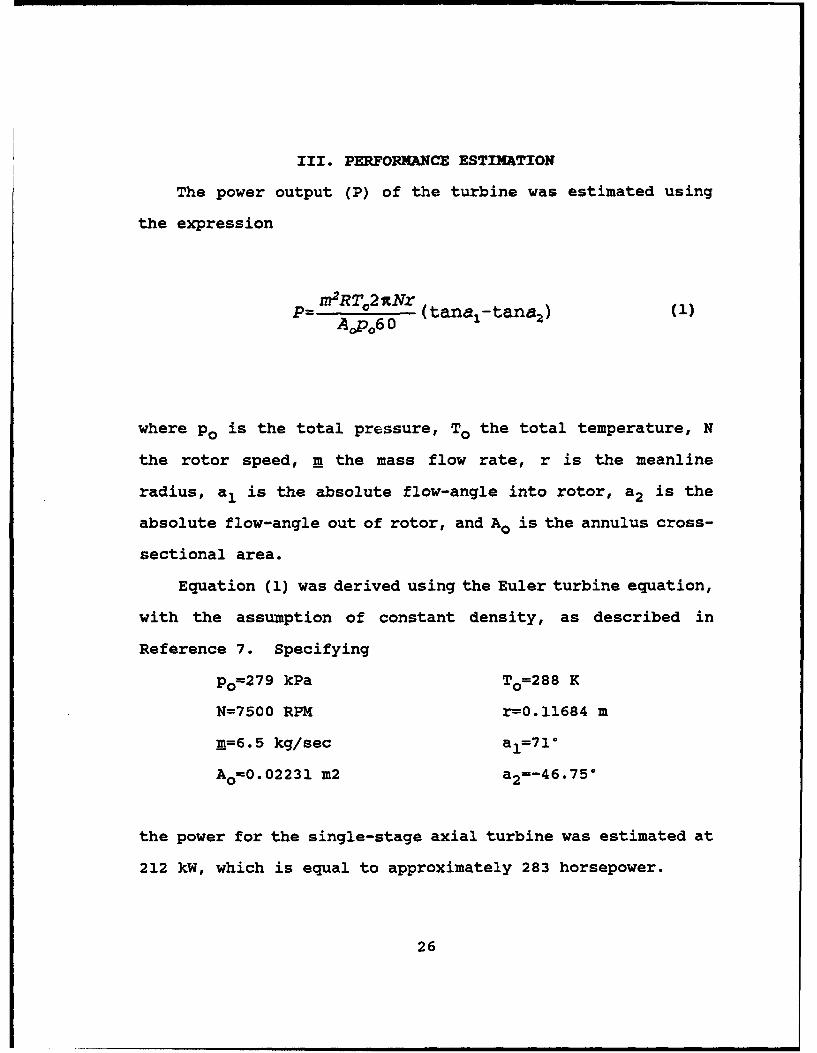
III. PERFORMANCE ESTIMATION
The power output (P) of the turbine was estimated using
the expression
P= n2RT,,2A (tana.-tana2 )
where po is the total pressure, To the total temperature, N
the rotor speed, m the mass flow rate, r is the meanline
radius, a, is the absolute flow-angle into rotor, a 2 is the
absolute flow-angle out of rotor, and Ao is the annulus cross-
sectional area.
Equation (1) was derived using the Euler turbine equation,
with the assumption of constant density, as described in
Reference 7. Specifying
Po=279 kPa To=288 K
N=7500 RPM r=0.11684 m
m=6.5 kg/sec al=71°
Ao=0.02231 m2 a 2=-46.75°
the power for the single-stage axial turbine was estimated at
212 kW, which is equal to approximately 283 horsepower.
26
IV. CONCLUSIONS AND RECOMMENDATIONS
A. CONCLUSIONS
A test rig has been designed for the High Pressure Fuel
Turbopump turbine of the Space Shuttle Main Engine. Inlet
piping was designed, fabricated, and installed to connect the
air supply to the turbine. Provisions were made for turbine
inlet instrumentation.
A single stage of the two-stage Pratt & Whitney "Alternate
Turbopump Development" model was assembled and installed on a
steel table within the test cell. The shaft and bearing
housing between the rotor and the hydraulic dynamometer were
designed, manufactured, and installed. The dynamometer was
refurbished and the speed control system was commissioned.
The upgraded cooling water system for the laboratory's Allis-
Chalmers (A/C) compressor required the addition of a pump to
recirculate the coolant. The control system instrumentation
was checked for integrity and functionality. An existing
recirculating oil system was used for bearing lubrication. A
performance estimate of the single-stage turbine was made
based on the pressure and temperature supplied by the A/C
compressor. The power output was within the operating
envelope of the dynamometer. Problems encountered during
27
balancing of the rotor and bearing housing assembly prevented
initial test operation of the system.
B. RECOMMENDATIONS
The following are recommended:
1. Install instrumentation for bearing temperature andvibration measurements.
2. Incorporate a mass-flow measurement device in theturbine air supply so that air from the A/C can be bypassedas a means of setting turbine inlet pressure.
3. Include more extensive instrumnetation for performancemeasurements.
4. Design and manufacture a new casing for LDV measurementswhich includes optical access windows over the rotor blades.
28
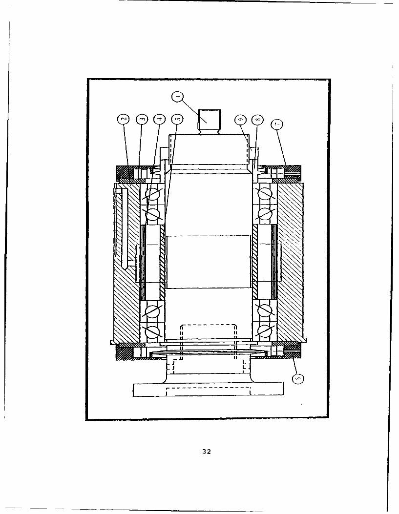
APPENDIX I.
This appendix contains engineering diagrams for the TTR
inlet piping and bearing housing components. Contents
include:
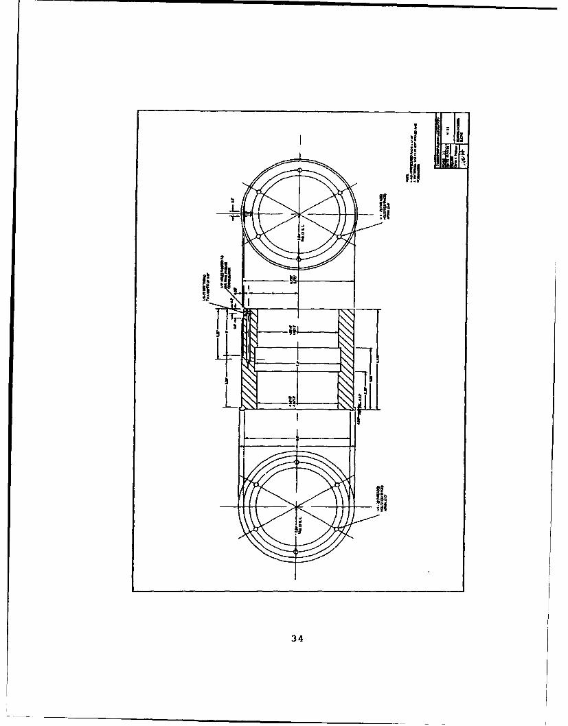
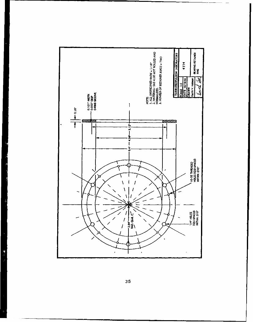
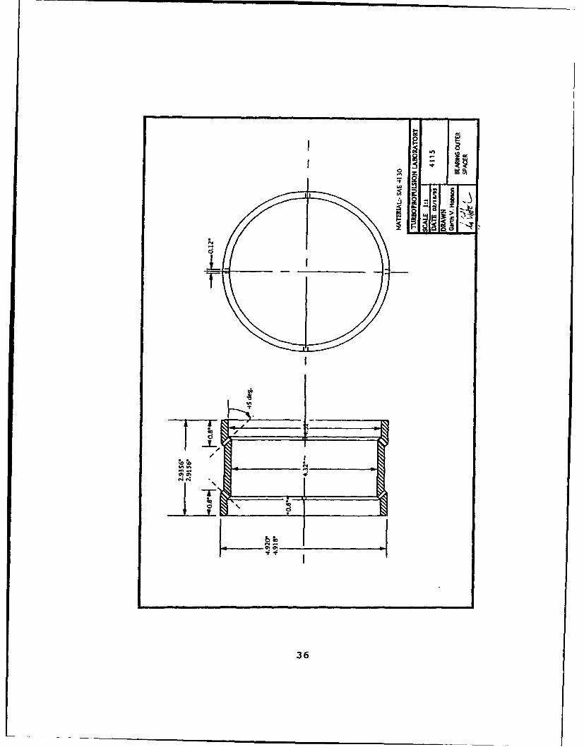
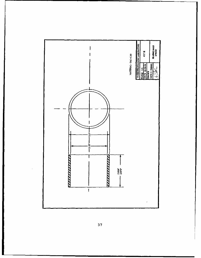
DRAWING PAGE NO
Inlet Piping 30Inlet Flange 31Bearing Housing Assembly 32Shaft 33Bearing Housing Sleeve 34Bearing Retainer Ring 35Bearing Outer Spacer 36Bearing Inner Spacer 37Oil Seal Front 38Oil Seal Rear 39Oil Flinger 40Retainer Nut 41
29
30
LAD
31
32
V-NVI SI2
37
•- - --
"I I T I3
33
P
I i "
34
El
Co
z
-o_
"2 O�2 L
35
_Ln
-0
/SO!
OiI
36
S0
S5
II
37
2-3
022
918-2- I
oom I-;
o .
_____________ __________ _____38___
0z~ W- -I
z _ _ _ _ _ _ _ _ _ _ _ _ _ _
I0
R 7
96 olz~_ _ _ _ IN_
0 T
39
0F- LU
0zLL-
0z0
0 m un X
Cr) N
40
41-
APPENDIX II.
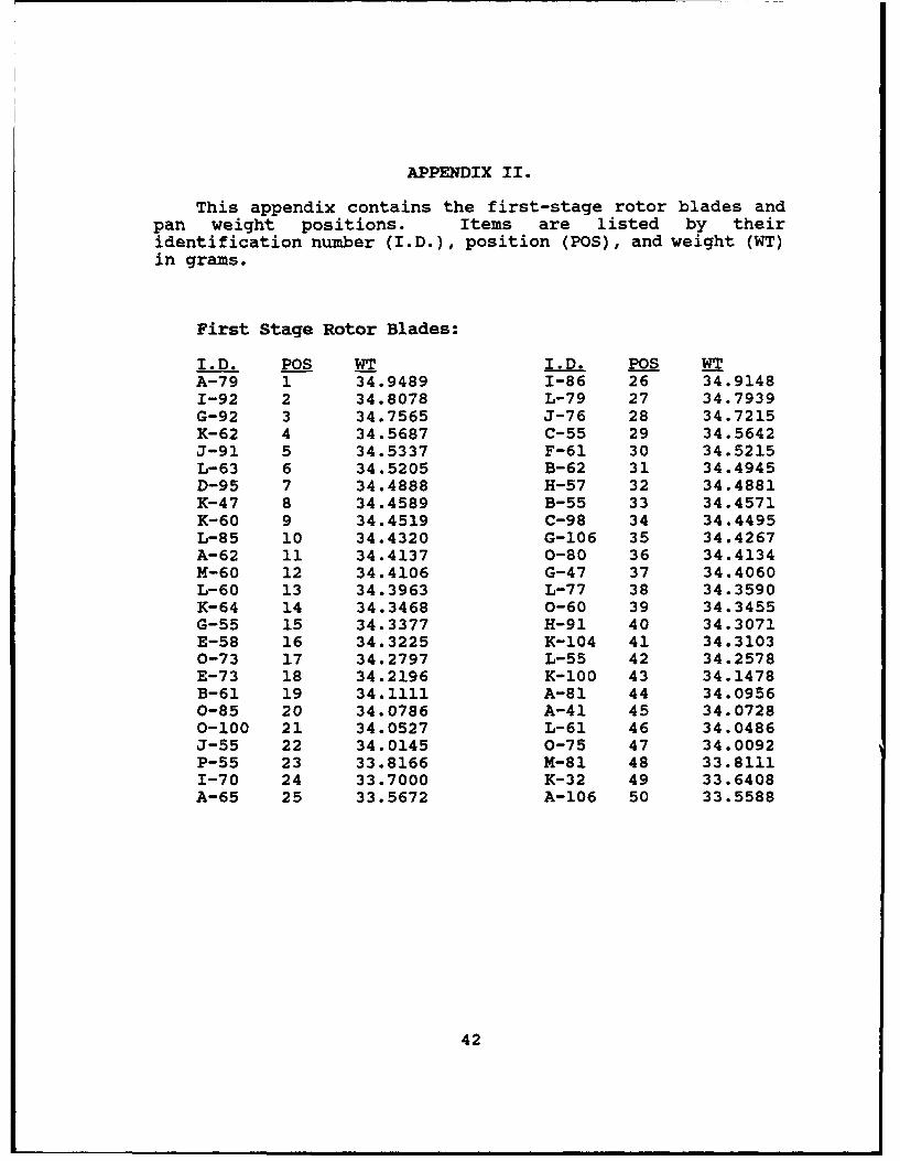
This appendix contains the first-stage rotor blades andpan weight positions. Items are listed by theiridentification number (I.D.), position (POS), and weight (WT)in grams.
First Stage Rotor Blades:
I.D. POS WT I.D. POS WTA-79 1 34.9489 1-86 26 34.91481-92 2 34.8078 L-79 27 34.7939G-92 3 34.7565 J-76 28 34.7215K-62 4 34.5687 C-55 29 34.5642J-91 5 34.5337 F-61 30 34.5215L-63 6 34.5205 B-62 31 34.4945D-95 7 34.4888 H-57 32 34.4881K-47 8 34.4589 B-55 33 34.4571K-60 9 34.4519 C-98 34 34.4495L-85 10 34.4320 G-106 35 34.4267A-62 11 34.4137 0-80 36 34.4134M-60 12 34.4106 G-47 37 34.4060L-60 13 34.3963 L-77 38 34.3590K-64 14 34.3468 0-60 39 34.3455G-55 15 34.3377 H-91 40 34.3071E-58 16 34.3225 K-104 41 34.31030-73 17 34.2797 L-55 42 34.2578E-73 18 34.2196 K-100 43 34.1478B-61 19 34.1111 A-81 44 34.09560-85 20 34.0786 A-41 45 34.07280-100 21 34.0527 L-61 46 34.0486J-55 22 34.0145 0-75 47 34.0092P-55 23 33.8166 M-81 48 33.81111-70 24 33.7000 K-32 49 33.6408A-65 25 33.5672 A-106 50 33.5588
42
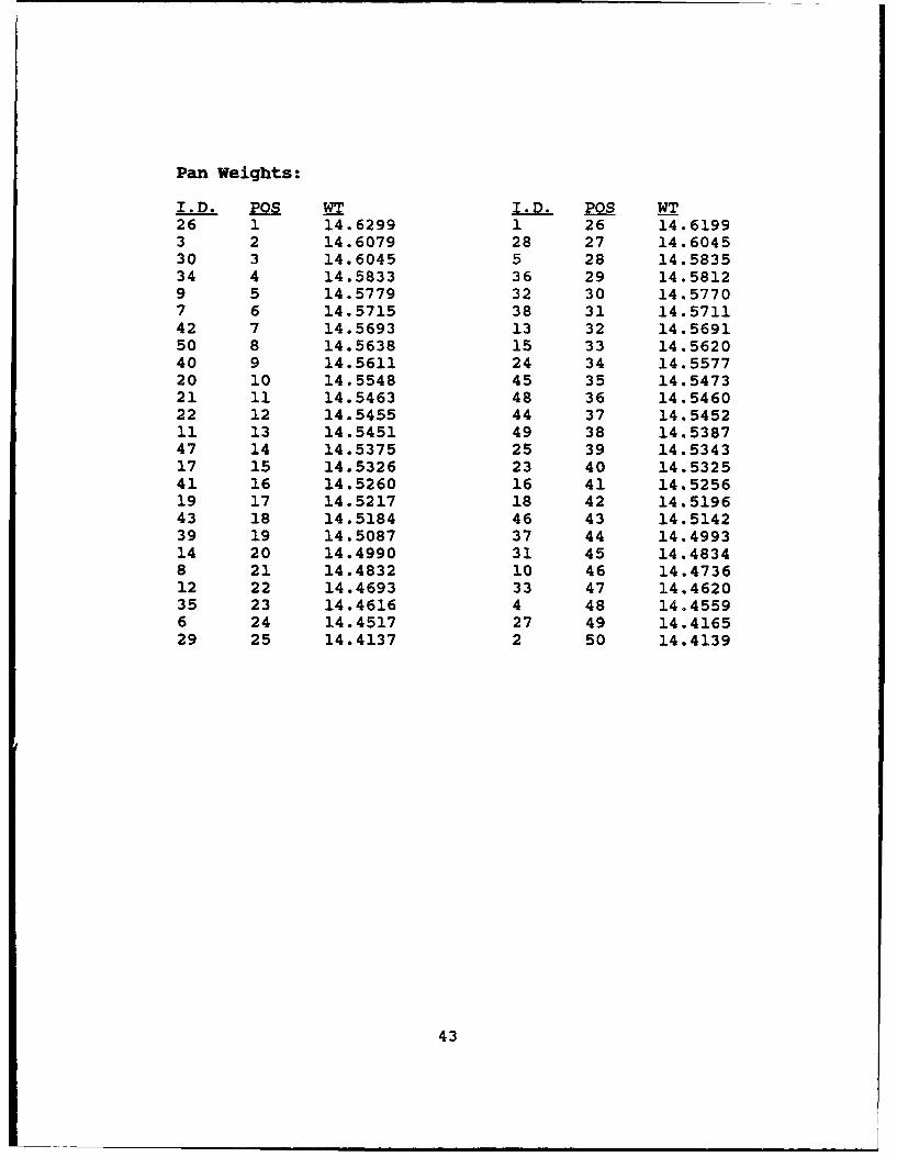
Pan Weights:
I.D. POS WT I.D. POS WT26 1 14.6299 1 26 14.61993 2 14.6079 28 27 14.604530 3 14.6045 5 28 14.583534 4 14.5833 36 29 14.58129 5 14.5779 32 30 14.57707 6 14.5715 38 31 14.571142 7 14.5693 13 32 14.569150 8 14.5638 15 33 14.562040 9 14.5611 24 34 14.557720 10 14.5548 45 35 14.547321 11 14.5463 48 36 14.546022 12 14.5455 44 37 14.545211 13 14.5451 49 38 14.538747 14 14.5375 25 39 14.534317 15 14.5326 23 40 14.532541 16 14.5260 16 41 14.525619 17 14.5217 18 42 14.519643 18 14.5184 46 43 14.514239 19 14.5087 37 44 14.499314 20 14.4990 31 45 14.48348 21 14.4832 10 46 14.473612 22 14.4693 33 47 14.462035 23 14.4616 4 48 14.45596 24 3.4.4517 27 49 14.416529 25 14.4137 2 50 14.4139
43
LIST OF REFERENCES
1.- Hudson, S. T. , Gaddis, W. S. , and Johnson, J. L. , "Cold FlowTesting of the Space Shuttle Main Engine High PressureFuel Turbine Model," AIAA Paper No.91-2503, paperpresented at the American Institute of Aeronauticsand Astronautics 27th Joint Propulsion Conference,Sacramento, California, 24-26 June 1991.
2. Gaddis, S.W., Hudson, S.T., and Johnson. P.D., "Cold FlowTesting of the Space Shuttle Main Engine AlternateTurbopump Development High Pressure Fuel TurbineModel," ASME Paper No. 92-GT-280, paper presented at theInternational Gas Turbine and Aeroengine Congress andExposition, Cologne, Germany, 1-4 June 1992.
3. Kane, W. J., Experimental Investigation of the Effects ofRotor to Stator Axial Spacina on the Performance of ASingle Stage Transonic Axial Turbine, M.S.M.E. Thesis,Naval Postgraduate School, Monterey, Ca, 1978.
4. Eargle, T.P., Evaluation of Factors AffectingRepeatability and Accuracy of Turbine Rigr Test Results,M.S.A.E. Thesis, Naval Postgraduate School, Monterey,Ca, 1980.
5. Instruction Manual Waterbrake Dvnamometer, Model 061-109,Kahn Companies, No. 9755, 1976.
6. Instruction Manual Automatic Dynamometer Speed ControlSystem, Kahn Industries, No. 1766A, 1976.
7. National Aeronautics and Space Administration, TurbineDesign and ARplication, by A.J. Glassman, pp. 21-62,Government Printing Office, Washington, DC, 1972.
44
INITIAL DISTRIBUTION LIST
No. Copies1. Defense Technical Information Center 2
Cameron StationAlexandria VA 22304-6145
2. Library, Code 052 2Naval Postgraduate SchoolMonterey CA 93943-5002
3. Department Chairman, AA 1Department of AeronauticsNaval Postgraduate SchoolMonterey, CA 93943
4. Garth V. Hobson, Turbopropulsion Laboratory 7Code AA/HgDepartment of AeronauticsNaval Postgraduate SchoolMonterey, CA 93943
5. Naval Air Systems CommandAIR-536T(Attn: Mr. Paul F. Piscopo)Washington, District of Columbia 20361-5360
6. Naval Air Warfare CenterAircraft Division (Trenton)PE-31(Attn: S. Clouser)250 Phillips BlvdPrinceton CrossroadsTrenton, NJ 08628-0176
7. Colin C. Studevan2110 Glenwood AvToledo, OH 43620
45