Embed Size (px)
Citation preview
flC FILE COPY,
NAVAL POSTGRADUATE SCHOOLMonterey, California
AD-A226 392DTICELECTE z -t
SEP 13 1990
SD
TIIESIS
3DSHIPS: RAPID 3D ICON GENERATION FORTHE COMMAND AND CONTROL WORKSTATION
OF THE FUTURE
by
Daniel Edwin Nagel
December 1989
Thesis Advisor: Michael J. Zyda
Approved for public release; distribution is unlimited
I ib n lam a I9 0 i lli

UNCLASS IFIEDSECURITY CLASSIFICATION OF THIS PAGE
REPORT DOCUMENTATION PAGEla. REPORT SECURITY CLASSIFICATION lb RESTRICTIVE MARKINGS
UNCLASS IFIED2a. SECURITY CLASSIFICATION AUTHORITY 3. DISTRIBUTION /AVAILABILITY OF REPORT
Approved for public release;2b. DECLASSIFICATION I DOWNGRADING SCHEDULE distribution is unlimited4. PERFORMING ORGANIZATION REPORT NUMBER(S) S. MONITORING ORGANIZATION REPORT NUMBER(S)
6.. NAME OF PERFORMING ORGANIZATION 6b. OFFICE SYMBOL 7a. NAME OF MONITORING ORGANIZATION
(If applicable)
Naval Postgraduate School Code 52 Naval Postgraduate School
k. ADDRESS (City, State, and ZIP Code) 7b. ADDRESS (City, State, and ZIP Code)
Monterey, California 93943-5000 Monterey, California 93943-5000
8a. NAME"OF FUNDING/SPONSORING 8b. OFFICE SYMBOL 9. PROCUREMENT INSTRUMENT IDENTIFICATION NUMSERORGANiZATION (if applicable) a
8c. ADDRESS (City, State, and ZIP Code) 10. SOURCE OF FUNDING NUMBERSPROGRAM PROJECT TASK WORK UNITELEMENT NO. NO. NO. ACCESSION NO.
1 l1 TITLE (Include Security Classification)
3b)SHIPS: RAPID 3D ICON GENERATION FOR THE COMMAND AND CONTROL WORKSTATION OFTHE FUTURE12. PERSONAL AUTHOR(S)Nagel. Daniel E.13a. TYPE OF REPORT 13b. TIME COVERED 14. DATE OF REPORT (Year, Month, Day) 15 PAGE COUNT
Master's Thesis I FROM TO 1989, December 4316. SUPPLEMENTARY NOTATION
The views expressed in this thesis are those of the author and do not reflect the officialpolicy or oition of the nt Defense or the U.S. Government.17. COSATI CODES 18. SUBJECT TERMS (Continue on reverse if necessary and identify by block number)
FIELD GROUP SUB-GROUP 3DShips; CCWF
19. ABSTRACT (Continue on reverse if necessary and identify by block number)
...)' The Command and Control Workstation of the Future (CCWF) project demon-strated the practicality of implementing a real-time graphics display toprovide a modern fleet commander with a realistic visual display of his arenaof operations.+Ret--j%- One drawback to that implementation is the limitednumber of vessel icons incorporated. The primary goal of this study is toprovide an interactive tool for the rapid generation of three dimensionalship icons suitable for use in the CCWF. By centering the icon definitionsaround a standard object file format and providing a program that allowsmanipulation of these components to construct numerQus complete ship iconsfrom a limited base of ship component files, the flexibility of the currentCCWF is enhanced. - .-
20. DISTRIBUTION /AVAILABILITY OF ABSTRACT 21. ABSTRACT SECURITY CLASSIFICATION93UNCLASSIFIEDIUNLIMITED 03 SAME AS RPT. 0 DTIC USERS Unclassified
22a. NAME OF ReSPONSIBLE INDIVIDUAL 22b. TELEPHONE (Include Area Code) e2c. OFFICE SYMBOL
Prof. Michael J. Zyda (408) 646-2305 Code 52ZkDD FORM 1473. 4 MAR 83 APR edition may be used until exhausted. SECURITY CLASSIFICATION OF THIS PAGE
All other editions are obsolete U.L @oAIWiiit 0111 0 0 1 -110624.
i UNCLASSIFIED

Approved for public release; distribution is unlimited
3DShips: Rapid 3D Icon Generation for the Commandand Control Workstation of the Future
by
Daniel Edwin NagelLieutenant Commander, United States Navy
B.A., College of Charleston, 1977
Submitted in partial fulfillment of the
requirements for the degree of
MASTER OF SCIENCE IN COMPUTER SCIENCE
from the
NAVAL POSTGRADUATE SCHOOLDecember 1989
Author: -a iAdisorr ~Daniel E. N4
Approved by: L a As Advisor
Leigh W. Bradbuty, Second Reader
DeyA~ment of Computer Science
ii

&~IBAI
ABSTRACT
The Command and Control Workstation of the Future (CCWF)
project demonstrated the practicality of implementing a real-
time graphics display to provide a modern fleet commander with
a realistic visual display of his arena of operations (Ref.
1]. One drawback to that implementation is the limited number
of vessel icons incorporated. The primary goal of this study
is to provide an interactive tool for the rapid generation of
three dimensional ship icons suitable for use in the CCWF. By
centering the icon definitions around a standard object file
format and providing a program that allows manipulation of
these components to construct numerous complete ship icons
from a limited base of ship component files, the flexibility (.,1
of the current CCWF is enhanced.
ACcEL"sI FO'
NTIS CR!&IDTC TAB LiUllanilouc:ed LiJustificjiu,
ByDistribution I
Availability Codes
Avail and/orDist Special
iii

TABLE OF CONTENTS
I. RAPID 3D ICON GENERATION---------------------------- 1
A. INTRODUCTION------------------------------------- 1
B. OVERVIEW----------------------------------------- 2
C. CHAPTER SUMMARY---------------------------------- 3
II. SIMULATOR BACKGROUND-------------------------------- 5
A. SIMULATOR EVOLUTION----------------------------- 5
B. DEVELOPMENT AND USE OF THE CCWF---------------- 6
III. METHODOLOGY------------------------------------------ 10
A. INITIAL GOALS----------------------------------- 12
B. IMPLEMENTATION----------------------------------- 12
IV. GENERAL TECHNIQUE TOPICS---------------------------- 14
A. LIGHTING---------------------------------------- 14
B. FILE FORMAT------------------------------------- 15
C. ADDITIONAL GRAPHICS TECHNIQUES----------------- 16
V. USER MANUAL----------------------------------------- 18
A. WINDOWS------------------------------------------ 18
VI. "13D SHIPS": IMPLEMENTATION SPECIFICS-------------- 25
A. MANIPULATION OF OBJECT FILES------------------- 25
B. COMBINE ------------------ --------------- 25
C. STORE-------------------------------------------- 27
D. PICKING----------------------------------------- 28
E. ROTATION---------------------------------------- 28
F. SCALING----------------------------------------- 29
iv

G. TRANSLATION ----------------- 29
H. RANGE-------------------------------------------- 29
*VII. SUMMARY---------------------------------------------- 31
A. CONCLUSIONS, LIMITATIONS AND FUTUREDIRECTIONS-------------------------------------- 31
APPENDIX: CREATING A NEW OBJECT FILE-------------------- 33
LIST OF REFERENCES----------------------------------------- 35
INITIAL DISTRIBUTION LIST--------------------------------- 36

ACKNOWLEDGMENTS
I would like to thank Lieutenant Dionissis Antonopoulos,
Hellenic Navy, for getting me started with the basic format
and organization of this project. Without his help in laying
the basic groundwork, things would have progressed infinitely
slower.
I also want to thank Lieutenant Steven Munson, USG, who
developed the Object File Format (OFF). His insight and
assistance in the beginning and his routines developed for use
with the OFF were invaluable tools in making this project
work.
Needless to say, I must extend my greatest gratitude to my
thesis advisor, Professor Michael Zyda, whose enthusiasm,
guidance and patience were boundless. Without his
introduction to graphics theory and the C programming
language, I would have truly found this project to be
insurmountable.
vi
I. RAPID 3D ICON GENERATION
A. INTRODUCTION
The need for rapid generation of three dimensional icons
is a direct result of the development of real-time three
dimensional graphics simulators. Research within the Naval
Postgraduate School, Computer Science Department's Graphics
and Video Laboratory has produced a number of simulation
projects, each of which depicts vehicle platforms of one or
more types. All designs were implemented on one of the family
of Silicon Graphics Inc. IRIS high performance graphics
workstations (i.e,, IRIS 3120, IRIS 4D/70G or IRIS 4D/70GT)
(Ref. 2]. These simulators provide three dimensional views
for the user from a vehicle platform and allow the user to
interactively control various aspects of the platform's
environment.
The series of simulators began with the Fiber Optically
Guided Missile (FOGM) simulator. The FOGM simulator allows a
user to see a three dimensional view from a missile as it
flies from launch to target. There have also been
implementations of ground, sea and other airborne moving
platform simulators. With each successive project, the
implementations drew on and added to the features of
predecessors and took advantage of advances in hardware and
1

software capabilities to provide more functionality and
options for the user (Ref. 3:pp. 2-6].
Within each simulator, vehicle platforms have been
individually constructed and included as an integral component
of the simulator's functional code. As such, one limiting
factor in each simulator's ability to depict the real world
has been the programmers' scope of the simulator's functional
environment. Only those platforms envisioned and constructed
by the programmers are available to be used in simulation.
Addition of platforms other than those originally included
requires a user to conceive and implement the object in
programming language code so that it may be included in the
simulator's program code. By providing an interactive tool
that allows a user to custom design platforms that match the
currently intended application, a simulator goes one step
closer to providing a more realistic depiction of the intended
environment.
B. OVERVIEW
This study focuses on the rapid generation of three
dimensional icon platforms for the Command and Control
Workstation of the Future (CCWF), a real-time simulator for
surface and subsurface naval vessels [Ref. 1]. The CCWF is
one of the latest generation simulators designed at the Naval
Postgraduate School, and lends itself to modular decomposition
of its icon platforms more than any of the other designs.
2

This is mainly attributable to many naval vessels sharing
similar hull designs, superstructure components and other
auxiliary structures. Being one of the most current designs,
the CCWF also exhibits a high degree of exploitation of the
hardware and software features and capabilities of the IRIS
4D/70GT.
The design tool is called 3DShips and objects used to
construct the 3D icons are referred to as either base objects
or add objects. The term base object refers to a hull or ship
icon that is to be built upon. These objects are of a fixed
size and are exempt from scaling operations, as well as other
manipulation. Base objects form the center of operations
around which add objects are manipulated. As implied, add
objects are auxiliary objects that are used to complete the
construction of a ship icon.
C. CHAPTER SUMMARY
The study of three dimensional icon generation involved
the study and understanding of previous research, with use and
modification of many aspects of that previous work, as well as
independent work. In Chapter II, the real-time simulator
background and the need for three dimensional icon generation
is discussed. Chapter III covers the premises and goals of
the study. In Chapter IV, general implementation topics,
including hardware based graphics support and file format are
covered. Chapter V is a user's manual. The specific
3

implementation for 3DShips is covered in Chapter VI, and the
limitations and future directions are the subject of Chapter
VII.
4

II. SIMULATOR BACKGROUND
In order to fully appreciate the need for the rapid
generation of three dimensional icons for the CCWF, it is
important to first understand what is meant by an icon in the
context of this study. Simply stated, it is a graphic symbol
that easily conveys the idea of the object it is meant to
represent. Secondly, understanding the design and evolution
of the simulator gives the full insight into the need for such
icons.
A. SIMULATOR EVOLUTION
The CCWF evolved from a long line of real-time platform
simulators. The need for such simulation devices is driven by
the ever-increasing costs involved in operating in the actual
environments that these devices are designed to emulate, as
well as the added safety factor for personnel and equipment
that need not be unnecessarily exposed to hazardous operating
conditions.
The CCWF was a logical follow-on to the research involving
aerial and land-based simulators that depict movement on or
above a strictly terrestrial environment [Ref. l:p. 4]. The
CCWF system presents accurate three dimensional views of
movement through a marine environment from either a surface or
a subsurface vessel.
5

B. DEVELOPMENT AND USE OF THE CCWF
Since accurate submarine terrain data were unavailable, a
terrain database was constructed using Defense Mapping Agency
geographic data on islands in the Sea of Japan. Once this
database was complete, the islands were "artificially" sunk to
provide a sea surface over known terrain. Areas that mapped
bodies of water were considered "deep water," inaccessible to
the submarine platforms of the simulator.
Once the program is entered, a full view of the desired
map area is presented to the user with an overlay of grid
squares (Figure 2.1). These squares provide a wide range of
choices for the placement of vessel platforms and choice of
initial operating areas.
The user chooses from a menu of ship types, and where
within the chosen grid square to place it (Figure 2.2). This
interaction continues until the user has placed the desired
number of platforms in all the desired grid squares.
When a user chooses a platform to drive, the simulator
provides a three dimensional view from the chosen platform and
provides for interactive modification of its performance
(Figure 2.3). That is to say, the platform's course, speed
and depth (if it is a submarine platform) and the viewer's
perspective (i.e., looking forward, left, right, etc.).
Once a platform is chosen, operation is unrestricted
(within the confines of the mapped area) and does not prevent
any vessels from traveling from grid to grid.
6
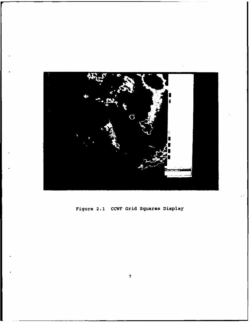
Figure 2.1 CCWF Grid Squares Display
7

Figure 2.2 CCWF Vessel Placement Display
8

Figure 2.3 CCWF 3D View from Bridge of Vessel
9
III. METHODOLOGY
The CCWF is as sophisticated a simulation as any produced
to date in the Graphics and Video Laboratory at the Naval
Postgraduate School. The graphics techniques and methods
utilized in the implementation provided the basis for the
interface used to design the vessel platform icons.
Three dimensional scenes are displayed using filled
polygons to approximate curved surfaces. It follows that,
generally, as the number of polygons increases, curved
surfaces will take on a smoother appearance. Likewise, the
detail of a picture can be increased by using more and smaller
polygons. The major liability of this approach to displaying
animated objects is the proportionally longer time it takes
the hardware to complete the picture, proportionally slowing
the animation.
Real-time animation is considered to be approximately 30
frames per second [Ref. 4:p. 43]. Although the CCWF falls
well short of this performance (evidenced by CCWF performance
data in Figure 3.1 [Ref. 1:p.79]), a reasonably real-time
update rate is a must to insure the user is provided with
current information. This "reasonable update rate" does not
have to provide the appearance of fluid motion in order to
display real-time information and retain the functional
utility of a real-time simulator.
10

CCWF Performance Table
View View Frames PolygonsDraw Method Angle Distance Polvons per sec per sec
Grid Square 45 5,000 1,531 5.8 8,880Mesh 45 5,000 1,531 10.0 15,310
Grid Square 15 5,000 863 10.6 9,148Mesh 15 5,000 863 16.4 14,153
Grid Square 45 7,500 1,786 4.9 8,751Mesh 45 7,500 1,786 9.6 17,146
Grid Square 15 7,500 947 9.9 9,375Mesh 15 7,500 947 15.6 14,773
Grid Square 45 15,000 2,790 3.3 9,207Mesh 45 15,000 2,790 5.9 16,461
Grid Square 15 15,000 1,333 7.2 9,598Mesh 15 15,000 1,333 11.3 15,063
Grid Square 45 20,000 3,732 2.2 8,210Mesh 45 20,000 3,732 4.3 16,047
Grid Square 15 20,000 1,675 5.3 8,878Mesh 15 20,000 1,675 9.0 15,075
Figure 3.1 CCWF Performance Data
Because the value of the display for the CCWF depends
primarily on the volume of real-time scenario data that can
be displayed and updated, there is a necessary limit to the
amount of detail that can be included for each ship icon. The
IRIS 4D/70GT is a state of the art graphics workstation
capable of an advertised performance of 40,000 Gouraud shaded,
lighted, four-sided polygons per second (performance
statistics are obtained with proprietary methodology and
actual performance is dependent upon display complexity) [Ref.
11

3: pp. 1-3]. This performance capability was a driving force
in determining icon complexity.
A. INITIAL GOALS
The primary objective in the design of 3DShips was
production of complete ship icon files that are sufficiently
distinct to allow rapid recognition and there icon files are
stored in the standard object file format (OFF) used by the
CCWF. Secondarily, but also of prime importance, is that icon
complexity is such that real-time scenario display performance
of the CCWF is not degraded to an unreasonable degree.
B. IMPLEMENTATION
Implementation of ship icon construction tool required
that certain premises be established first. These premises
were kept simple, but provided the general guidance for the
study.
First, not just the final ship icons, but all graphics
definitions for objects that go into the construction of the
vessel models have to be in a standardized file format. The
format chosen was one defined by prior research studies [Ref.
5]. The specific format, OFF, is covered in more detail
below.
Second, the final composite vessel models should be of a
level of complexity that allows easy and positive recognition
of the vessel type being modeled, yet not be so complex that
an unreasonable percentage of the simulator's CPU time is
12

spent rendering the polygons for the vessel icons. Although
this is a very subjective number whose upper limit varies
depending on the number of vessel icons in use at any one time
and the hardware display capability, vessel models of 200-300
polygons seem to offer a satisfactory compromise between
graphic accuracy and system performance for the IRIS 4D/70GT.
With only two simple premises to guide the direction of
the study, great flexibility was available to pursue this
project. With no other restrictions, various implementation
techniques were attempted with the choice going to that which
produced the best results.
13

IV. GENERAL TECHNIOUE TOPICS
A. LIGHTING
The perception of objects in the real world is dependent
upon a number of factors, including: the color, location and
direction of the light source illuminating the objects; the
color and surface properties of the objects themselves; and
the position and viewing direction. Also, the objects used to
portray the components of the vessel models in the design tool
are totally defined by a jigsaw puzzle of flat-sided polygons.
In addition to these two facts of life, the file format used
to specify all the objects displayed in the vessel design tool
included lighting facilities of the IRIS [Ref 6:p. 9-1].
Consequently, a simple lighting calculation was required to
permit use of the file format and provide the shading of
polygons to give objects a more smooth and realistic
appearance.
For the IRIS hardware to compute the lighting of a
polygon, a surface normal vector must be provided for every
polygon defined. This "normal" is used in a Lambert's cosine
model and Phong model for lighting the polygon [Ref. 7:pp.
278-280].
When many polygons are used to construct an object, a
lighting calculation must be utilized to provide an averaging
of surface normals for each vertex where polygons intersect in
14

order to Gouraud shade across the adjacent polygons. In
addition, the incidence and reflection of ambient light
(nondirectional light that arrives from and is reflected in
all directions simultaneously) must be accounted for. All of
these factors are handled by a hardware resident lighting
model of the IRIS workstation that interprets the simple
lighting calculation included in the program code as a command
to use the system's default lighting parameters [Ref. 6:pp.
9-1--9-9].
B. FILE FORMAT
3DShips was implemented with a design that expects every
object displayed in the icon construction process to be in a
standard ASCII text-based file format. This format was
modeled around the IRIS lighting and modeling facilities and
is suitable for specifying objects in any of the series of
real-time three dimensional visual simulators designed in the
Graphics and Video Laboratory at the Naval Postgraduate
School, as well as most other application programs for an IRIS
workstation.
This object file format was implemented to display objects
that take advantage of the advanced graphics capabilities of
state-of-the-art graphics hardware and software. As currently
designed, the OFF consists of a dynamically allocated data
structure that holds up to five different types of
substructures (nodes) that define the physical display
15

characteristics of an object. These nodes can contain the
data that define the material, color, line, polygon, and/or
surface definitions for an object to be displayed [Ref. 5:p.
23].
The OFF was designed to be used in preview and
modification tool applications [Ref. 5:p. 23], so its dynamic
structure facilitated ease of use in the design tool for three
dimensional icons. For a complete discussion of OFF see [Ref.
5.].
C. ADDITIONAL GRAPHICS TECHNIQUES
Two important IRIS graphics utilities are used in 3DShips
to provide accurate and updated displays. As before, they are
resident in the IRIS Graphics Library and hardware.
Z-buffering--by tracking the z-value for each filled pixel
on the screen and drawing those that are farthest first and
closest last, three dimensional objects can be drawn
displaying only those lines and polygons that depict the
surfaces that would be seen on an actual object [Ref. 7:pp.
262-264]. In other words, hidden surfaces are eliminated as
an object is drawn.
Double buffering--this graphics technique divides a
systems standard bitplanes in half so that while halr are used
to display an object (front buffer), the other half can be
updated unseen (back buffer), to be displayed when needed.
This is a cyclic process where the front and back buffers are
16

continually swapped as a display is updated [Ref. 6:p. 6-1].
This technique is used in 3DShips to update displays as
objects are added and viewpoints change, but is also extremely
important in animated programs. The only animation in 3DShips
is achieved when objects are translated within the program to
place them correctly. Therefore, animation is not of great
concern in this study.
17

V. USER MANUAL
The interface of 3DShips was designed to provide the user
with a simple and efficient means of custom construction of
three dimensional naval vessel icons suitable for use in the
CCWF simulator. The use of numerous icons and popup menus was
intended to facilitate this ease of use.
A. WINDOWS
When the program is initiated, the user is presented with
a view of four separate windows (see Figure 5.1 and 5.2). As
use of the program continues, these windows are updated and
redrawn. A detailed description of each window follows.
1. Icon Window
The Icon Window is located at the top of the screen
and is easily distinguished by the row of icons representing
the basic options in the program. This window comprises the
main user interface. Within this window, all menu selections
are with the right mouse.
There are eight icon blocks in the window. With the
exception of the last two icons, by positioning the mouse
cursor in the icon block and clicking the right mouse button,
a user is presented with a pop-up menu that depicts program
options. Proceeding from left to right the icons are:
18

Coordinates Window
'' Instruction & Menu Window
TopView
WindowThe * DimensionalWindow
Slider Bar
Note I I through 18 are Icon Menus
Figure 5.1 Window Identification
-Armament (see il, Figure 5.1).
-Hulls (see 12, Figure 5.1).
-Superstructures (see D3, Figure 5.1).
-Masts (see 14, Figure 5.1).
-Select Ships (see 15, Figure 5.1).
-Control (see i6, Figure 5.1).
-Scale Up (see i7, Figure 5.1).
-Scale Down (see 18, Figure 5.1).,
19

Figure 5.2 3DShips Display
a. Armament
Armament allows the user to select any available
armament to be added to the vessel platform being constructed.
Armament is considered to be an "auxiliary" or "add on"
object, not a main structure. As many auxiliary objects as
desired can be added to a construction, however, one must be
combined with the existing object before another can be added.
b. Hulls
Hulls also allows the user to select any available
hull type to be built upon. Hulls are considered to be a
"main" or "base" object and as such only one is allowed to be
built upon at a time.
20
c. Superstructures and Masts
Superstructures and masts are the next two icons
and are also auxiliary objects. They are handled and treated
the same as other auxiliary objects.
d. Select Ships
The ship selection icon provides a listing of
predefined ship structures and current user-customized vessel
platforms. All of these platforms are considered a base
object and as such can be further customized by the user.
e. Control
The control icon contains a menu with most
powerful options in the 3DShips program. The following
provides a brief description of the functionality of each menu
option:
- Remove Base Obiect--Deletes the currently drawn baseobject and all components that have been added thus farto allow a new base object to be brought in and builtupon.
- Remove Add Object--Deletes the current add object thatis being manipulated so that a new one may be brought in.
- Combine Objects--Combines the current add object with thecurrent base object, making that combination the newcurrent base object. Without a "combine" or a "remove"of an add object, no new add objects can be brought in.
- Save--Saves the current base object and writes it out asa permanent single file of the composite base object.The file will have the name Shipl.new, Ship2.new, etc.
- Pick--Puts the 3D window in the "pick" mode to allow auser to select any add object that was previouslycombined with the base object and delete it. When "pick"is selected, the mouse is used to place the cursor on thecenter of the object to be deleted and the middle mousebutton is clicked. Once "picked" an object will no
21

longer become a part of the permanent "save" file, ifthat option is selected. If a "pick" misses the object,the message buffer will display "Nothing picked" anddisappear. The "pick" mode must then be reentered.
Rotate--If selected, this option will rotate the currentadd object 1800.
Exit Proaram--Self explanatory, returns control back tothe operating system.
f. Scale Up and Scale Down
These are the only icon blocks that have no pop-
up menu associated with them. Their function is simply to
scale the current auxiliary object up or down, respectively,
by a scale factor of one-tenth for each time the right mouse
is clicked when the mouse cursor is located in one of the icon
boxes.
2. Coordinates Window
The blue coordinates window is located in the upper
right hand corner of the icon window. This window maintains
an updated location of the origin for an auxiliary object as
it is translated and moved about. By default, if no auxiliary
object is present, it maintains the location of where the
origin will be when the next auxiliary object is brought in.
This origin location is always relative to the origin of a
base object, whose origin remains constant. The origin for
the base object in the three digmensional window is located at
zero X, zero y and zero y.
The coordinates are manipulated via control box dials
four, five and six. Dial four controls movement along the y
22

axis; dial five controls movement along the X axis; and dial
six controls movement along the y axis. At program start up,
the default coordinates are (0.0,0.0,0.0). Manipulation of
desired coordinate position can be done at any time and does
not require an auxiliary object to be present.
3. Three Dimensional Window
The three dimensional window is the main display
window and as its name implies, it is the only three
dimensional viewing window in the program. Its displays the
desired vessel platforms in three dimensions and allows the
user to use viewing transformations to view the construction
from different angles to get an overall view.
Viewing transformations are invoked through pop-up
menus which can be called by placing the mouse cursor anywhere
in the three dimensional window and clicking the right mouse
button. Options for the transformations are:
- Moving the viewpoint up and down along the y axis.
- Moving the viewpoint around the vessel on the x and zaxes.
- Moving the viewpoint in and out along the I axis.
These transformations can also be combined for a cumulative
effect.
4. Top View Window
The top view window is a two dimensional viewing
window that is used to provide visual alignment cues to
complement the coordinates in the coordinates window. This
23

window enables the user to gain a rough placement for objects
by having a polar view directly down the y axis from above.
The viewpoint for this window never changes and there are no
pop-up menus associated with this window.
5. Slider Window
The slider window is drawn on top of the 3D Window and
depicts a single vertical slider bar. This bar is used to
interactively change the lookat viewpoint range. The default
at program initialization is from 300 feet back. The slider
can be used to push the range back to allow larger icons to be
displayed, without being clipped off, or to gain a perspective
of the icon from a greater range.
24

VI. "3DSHIPS": IMPLEMENTATION DETAILS
A. MANIPULATION OF OBJECT FILES
All object files are written in the OFF [Ref. 5]. To
dynamically draw and manipulate these objects, 3DShips takes
advantage of many of the manipulation routines of [Ref. 5].
The use of pre-existing functions and routines requires an
understanding of their design and often, modification to
tailor their functionality to fit a desired operation.
B. COMBINE
To have more than one active add object at any one time is
confusing and difficult to control. The most convenient
programming approach is to have one add object, and only bring
in another when the previous object has been placed or
discarded. To place an object requires a combine operation,
while discarding an object is as easy as deleting its dynamic
data structure.
Once a file has been read, it is stored for dynamic use
within 3DShips in an objectheader structure (Figure 6.1)
[Ref. 5:p. 24]. To combine objects, it is a simple matter of
setting up distinctly numbered pointers and using them to link
the "drawlists" of two object-headers together. After
combining two objects, the added object header is discarded
and the program is free to bring in another object. The newly
25

/* define the OBJECT HEADER structure type */typedef struct objectheader OBJECTHEADER;
struct objectheader /*main head node for theproject*/
(char *title; /*object title*/char *date; /*date of object file*/float origin[3]; /*object origin*/float maxx, /*max and min x,y,z */
minx, /*coordinates of the polygons */maxy, /*or surfaces of the object.*/miny,maxz,minz;
/*ptrs to head and tail of list of light definitions*/doubleptr head lightdefs;double ptr tail lightdefs;
/*ptrs to head and tail of lighting model definitions*/double ptr head modeldefs;doubleptr tail-modeldefs;
/*ptrs to head and tail of material definitions*/double ptr headmaterialdefs;double ptr tailmaterialdefs;
/*ptrs to head and tail of color definitions*/doubleptr head colordefs;double ptr tail-colordefs;
/*ptrs to head and tail of line definitions*/double ptr head linedefs;doubleptr tail-linedefs;
/*ptrs to head and tail of polygon definitions*/doubleptr head_polygondefs;doubleptr tail_polygondefs;
/*ptrs to head and tail of surface definitions*/double_ptr headsurfacedefs;doubleptr tail surfacedefs;
/*ptrs to head and tail of list of draw routines*/doublejptr head drawlist;doubleptr tail-drawlist;)
Figure 6.1 Objectheader Data Structure
26

combined object is a part of the base object's drawlist, but
the numbered pointer structure retains the object's file name.
This filename is needed when a composite base object is
saved.
C. STORE
The store operation is the most permanent type of
combining operation. With a store, the dynamic structure
holding a created icon's definition is converted to a
permanent ASCII object file. Once this file is created,
3DShips can still access and modify the icon, but if stored
again, the modified icon is stored in a separate and distinct
object file.
To store a completed icon in a file, it is necessary to
individually read each file for an object that has been added
to an icon and is to become part of the new composite file.
This is required because all comments from the files are
discarded as each is object is brought into 3DShips for
display. These comments are retrieved as each file is reread
during the store operation. Modifications, such as
translations and new scale factors, are obtained from the base
object's drawlist. The base object, followed in succession by
each added object, is appended, with its modifications, such
as translations and new scale factors, are obtained from the
base object's drawlist. The base object, followed in
succession by each added object, is appended, with its
27

modifications, and original comments, to the new composite
icon text file.
D. PICKING
Picking is accomplished using the pointer structures that
were created for the drawlist during the "combine" routine.
By including a flag to mark an object for either addition or
deletion in the pointer structure, the "save" routine
determines whether an object file should be opened for
appending to the output icon file. To determine whether an
object has been selected for deletion, a square box is drawn
by pickndelete()'s pseudo draw routine at each object's origin
to define the pick area. The dimensions of the picking region
are assigned when an add object is combined with a base
object. The picking region is the equivalent of a square box,
20 feet per side (as measured in the world coordinates of the
3D Window).
E. ROTATION
Because an object on a ship is typically oriented fore or
aft, this routine is set up to only rotate an object a set
angle, 1800. All transformations of add objects are structured
in a similar fashion, a temporary pointer is set up and each
line, polygon and surface in the add object structure is
stepped through, one at a time, and transformed. One
difference in the rotate operation is that the add object is
first translated to the origin and then the trigonometric
28

values for a 1800 conversion about the y axis are applied. The
transformed object is then translated back to its original
position.
F. SCALING
Scaling enables custom fitting an object to an icon. In
this transformation, a scale factor of either 0.9 or 1.1 is
applied to each line, polygon and surface to achieve the
desired size.
G. TRANSLATION
It is the translation that allows an add object to be
placed in the proper locality on an icon. This transformation
takes dynamic input by reading the current offset for an ad.d
object's position from valuator input received from dials 4
(x), 5 (z), and 6 (y) of the dialbox (Figure 6.2). Input is
converted to a world coordinate position for each respective
axis and displayed in the Coordinates Window as well as being
used to transform the add object's position.
H. RANGE
As implied in the general discussion of perspective views,
a change in range changes nothing but the point from which an
object is being viewed. By changing the viewpoing distance,
a user is allowed closer scrutiny of a small object or a full
profile view of a large object.
29

00Y-AxIs
Z-AxIs X-AxIs00
Figure 6.2 Dial Box
The implementation of a slider to vary the range is
handled in the following manner. First a window is opened on
top of the 3D Window and a slider bar is drawn within. A
bounding box over the slider bar (in screen coordinates) is
used to determine if the left mouse is clicked to indicate a
desired change in range. Mouse position valuators are used to
establish the desired change in range.
30
VII. SUMMARY
A. CONCLUSIONS, LIMITATIONS AND FUTURE DIRECTIONS
This study was prompted by the need for a design tool that
could rapidly generate three dimensional ship icons suitable
for use in the current CCWF. The resulting design tool,
3DShips, is capable of rapidly generating a single file
containing the definition of a complete ship icon that was
constructed from numerous input files. This generated file's
format is identical to that already used for defining ship
icons in the CCWF.
1. ShiD ComDlexity
The complexity of a created ship icon is equal to the
sum of the complexity of the individual components that make
up the total icon structure. There is no limit on the total
number of polygons and/or lines that can be included in an
icon's design. If a user so desires, up to 100 components of
varying complexity can be added.
For this study, the components for only one ship class
are included in the design tool, an FFG-7 class frigate. When
constructed in proper configuration, this model is comprised
of 330 polygons and eight complex line definitions. Although
this slightly exceeds the subjective maximum goal of 200-300
polygons, there is an unnecessary amount of detail included in
many of the smaller object definitions that only becomes
31

justified when an object is scaled to an unnecessarily large
size.
2. Importing Files and Naming Files
All ship hulls and object file definitions are hard-
coded into the design tool and all output ship icon definition
files are numbered in succession as they are written (i.e.,
Shipl.object, Ship2.object, etc.). A more convenient and
flexible approach would be to allow the user to interactively
reauest object files and name output files (as they are
created) from within the design tool.
3. Weapons
The current CCWF has weapons packages that are linked
with specific icon types and one operational weapon platform.
This weapon storage within the CCWF allows for inclusion of a
path file or a pointer to a guidance routine [Ref. l:pp. 86-
87]. Although the design of a weapon platform icon is no
different than any other object design, the ability to include
a total weapons package that is dependent upon icon design and
has a corresponding guidance routine accessible, is a complex
issue.
4. Control Surfaces
A future goal of the CCWF is to include the ability to
interactively control the control surfaces of icons as they
are operated [Ref. 1:p. 87]. Should this feature be added to
the CCWF, 3DShips would likewise need to be modified.
32

APPENDIX
CREATING A NEW OBJECT FILE
1. Premises of 3DShips
To create new object files, it is not only important to
understand the Object File Format (OFF), but also other
premises that 3DShips was designed around. The following are
the basic premises:
- At program initialization, the default draw point islocated at coordinates (0.0,0.0,0.0).
- The initial lookat viewpoint is 300 feet away from theobject.
- By default, all base objects (main ship hulls) are drawnwith their origin at coordinates (0.0,0.0,0.0).Additionally, it should be noted that the origin is thecenter of the hull at the waterline.
- Origins for objects are assumed to be the center of theobject.
- All add objects (ship components to be added to mainhulls) are drawn at the location of the x, y, Kcoordinates displayed in the Coordinates Window.
- All objects are scaled in feet, plus or minus from theorigin, on each axis.
2. Constructing the Code
Experience shows that the most effective coding follows a
logical sequence. The following is a proven sequence for the
construction of an object file:
- First, make a drawing to depict all polygons and linesthat define an object. More than one may be necessary toshow all sides.
33

Define the coordinates, in feet from the origin, for eachpoint that will make up the object.
Use RGB color to define the color for each object anddetermine a material definition (i.e. emission, ambient,diffuse, specular, and shininess qualities) for eachobject, part of an object.
Combine code into a file of the same format as anexisting object file.
3. Adding Files to 3DShips
Files must currently be hard coded into the program of
3DShips. To do so, the following steps must be taken:
- Modify file qtest.c by searching the word "MOUSECLICK_IN-ICON" and then add your object's file as a new case.
- Each new case added must be supported by a pop-up menudefinition that can be found in the file bsaux.c bysearching for the comment "ICON MENU DEFINITION." Nested(Rollover) menus may be required as selections becomemore numerous.
34

LIST OF REFERENCES
1. Weeks, Gordon Kenneth, Jr. and Phillips, Charles Edward,Jr., The Command and Control Workstation of the Future,Master's Thesis, Naval Postgraduate School, Monterey,California, June 1989.
2. Silicon Graphics, Inc., Tuning Graphics for Your IRIS-4D,Version 1.0.
3. Fichten, Mark A., Jennings, David H. and Zyda, Michael J.,Meaningful Real-Time Graphics Workstation PerformanceMeasurements, A Summary Report, Naval Postgraduate School,Monterey, California, November 1988.
4. Harris, Frank E., Yurchak, John M. and Zyda, Michael J.,Preliminary Work on the Command and Control Workstation ofthe Future, Progress Report, Naval Postgraduate School,Monterey, California, August 1988.
5. Munson, Steven Alfred, Integrated Support for theManipulation and Display of 3D Objects for the Command andControl Workstation of the Future, Master's Thesis, NavalPostgraduate School, Monterey, California, June 1989.
6. Silicon Graphics, Inc., The Graphics Library User's Guide,Version 1.0.
7. Hearn, Donald and Baker, M. Pauline, Computer Graphics,Prentice-Hall, Inc., Englewood Cliffs, New Jersey, 1986.
35

INITIAL DISTRIBUTION LIST
No. Copies
1. Defense Technical Information Center 2Cameron StationAlexandria, Virginia 22304-6145
2. Library, Code 0142 2Naval Postgraduate SchoolMonterey, California 93943-5002
3. Dr. Michael J. Zyda, Code 52Zk 10Department of Computer ScienceNaval Postgraduate SchoolMonterey, California 93943-5000
4. LCDR Daniel E. Nagel 2371-A Bergin DriveMonterey, California 93943
5. John Maynard 1Naval Ocean Systems CenterCode 402San Diego, California 92152
6. Duane Gomez 1Naval Ocean Systems CenterCode 433San Diego, California 92152
7. James R. Louder 1Naval Underwater Systems CenterCombat Control Systems DepartmentBuilding 1171/1,Newport, Rhode Island 02841
36